WO2015194167A1 - ヒートポンプ装置 - Google Patents
ヒートポンプ装置 Download PDFInfo
- Publication number
- WO2015194167A1 WO2015194167A1 PCT/JP2015/003006 JP2015003006W WO2015194167A1 WO 2015194167 A1 WO2015194167 A1 WO 2015194167A1 JP 2015003006 W JP2015003006 W JP 2015003006W WO 2015194167 A1 WO2015194167 A1 WO 2015194167A1
- Authority
- WO
- WIPO (PCT)
- Prior art keywords
- air
- evaporator
- heat
- refrigerant
- temperature
- Prior art date
- Legal status (The legal status is an assumption and is not a legal conclusion. Google has not performed a legal analysis and makes no representation as to the accuracy of the status listed.)
- Ceased
Links
Images





Classifications
-
- F—MECHANICAL ENGINEERING; LIGHTING; HEATING; WEAPONS; BLASTING
- F25—REFRIGERATION OR COOLING; COMBINED HEATING AND REFRIGERATION SYSTEMS; HEAT PUMP SYSTEMS; MANUFACTURE OR STORAGE OF ICE; LIQUEFACTION SOLIDIFICATION OF GASES
- F25B—REFRIGERATION MACHINES, PLANTS OR SYSTEMS; COMBINED HEATING AND REFRIGERATION SYSTEMS; HEAT PUMP SYSTEMS
- F25B27/00—Machines, plants or systems, using particular sources of energy
- F25B27/02—Machines, plants or systems, using particular sources of energy using waste heat, e.g. from internal-combustion engines
-
- F—MECHANICAL ENGINEERING; LIGHTING; HEATING; WEAPONS; BLASTING
- F25—REFRIGERATION OR COOLING; COMBINED HEATING AND REFRIGERATION SYSTEMS; HEAT PUMP SYSTEMS; MANUFACTURE OR STORAGE OF ICE; LIQUEFACTION SOLIDIFICATION OF GASES
- F25B—REFRIGERATION MACHINES, PLANTS OR SYSTEMS; COMBINED HEATING AND REFRIGERATION SYSTEMS; HEAT PUMP SYSTEMS
- F25B39/00—Evaporators; Condensers
- F25B39/04—Condensers
-
- F—MECHANICAL ENGINEERING; LIGHTING; HEATING; WEAPONS; BLASTING
- F25—REFRIGERATION OR COOLING; COMBINED HEATING AND REFRIGERATION SYSTEMS; HEAT PUMP SYSTEMS; MANUFACTURE OR STORAGE OF ICE; LIQUEFACTION SOLIDIFICATION OF GASES
- F25B—REFRIGERATION MACHINES, PLANTS OR SYSTEMS; COMBINED HEATING AND REFRIGERATION SYSTEMS; HEAT PUMP SYSTEMS
- F25B47/00—Arrangements for preventing or removing deposits or corrosion, not provided for in another subclass
- F25B47/02—Defrosting cycles
-
- Y—GENERAL TAGGING OF NEW TECHNOLOGICAL DEVELOPMENTS; GENERAL TAGGING OF CROSS-SECTIONAL TECHNOLOGIES SPANNING OVER SEVERAL SECTIONS OF THE IPC; TECHNICAL SUBJECTS COVERED BY FORMER USPC CROSS-REFERENCE ART COLLECTIONS [XRACs] AND DIGESTS
- Y02—TECHNOLOGIES OR APPLICATIONS FOR MITIGATION OR ADAPTATION AGAINST CLIMATE CHANGE
- Y02A—TECHNOLOGIES FOR ADAPTATION TO CLIMATE CHANGE
- Y02A30/00—Adapting or protecting infrastructure or their operation
- Y02A30/27—Relating to heating, ventilation or air conditioning [HVAC] technologies
- Y02A30/274—Relating to heating, ventilation or air conditioning [HVAC] technologies using waste energy, e.g. from internal combustion engine
Definitions
- the present disclosure relates to a heat pump apparatus that performs a defrosting operation for defrosting when frost is formed in an evaporator of a heat pump cycle.
- Patent Document 1 discloses a heating system that heats the air in a greenhouse with a radiator of a heat pump cycle and performs heating in the greenhouse as a heat pump device of this type.
- the heat pump device (heating system) of Patent Document 1 includes a duct that guides the air in the greenhouse to the evaporator side.
- the compressor of the heat pump cycle is stopped.
- the defrosting operation is performed by guiding the air (exhaust gas) discharged from the greenhouse for ventilation through the duct to the evaporator side.
- the defrosting operation is performed by guiding the exhaust gas to the evaporator side as in the heat pump device of Patent Document 1
- the start of the defrosting operation starts from the start of the defrosting operation.
- the defrosting time until the defrosting is completed also changes. That is, when the temperature and humidity of the exhaust gas are reduced, the defrosting time is prolonged.
- This indication aims at shortening of a defrost time in the heat pump apparatus which performs a defrost operation in view of the said point.
- the amount of heat necessary to complete the defrosting of the evaporator in the heat pump cycle is not only the amount of heat necessary for melting the frost generated in the evaporator, but also the amount of heat for heating the evaporator main body, etc. Is also required.
- the heat pump device includes a heat pump cycle, a heat source air introduction unit, a frost determination unit, and a control unit.
- the heat pump cycle includes a compressor that compresses and discharges the refrigerant, a radiator that exchanges heat between the high-pressure refrigerant discharged from the compressor and the fluid to be heated, a decompression unit that decompresses the refrigerant flowing out of the radiator, and a decompression unit. And an evaporator that evaporates the low-pressure refrigerant by exchanging heat between the low-pressure refrigerant decompressed and the air.
- the heat source air introduction unit guides heat source air having a temperature higher than that of the outside air to the evaporator side.
- a frost formation determination part determines whether frost formation has arisen in the evaporator.
- a control part performs the defrost operation for performing defrosting of an evaporator, when it determines with the frost determination part having produced frost in the evaporator.
- the controller as the defrosting operation, a first defrosting operation that causes a refrigerant having a temperature higher than that of the low-pressure refrigerant to flow into the evaporator when the frosting determination unit determines that frosting has occurred, and a heat source
- a second defrosting operation in which the heat source air is guided to the evaporator side by the air introduction unit can be executed.
- the first defrosting operation and the second defrosting operation are configured to be executable, the low-pressure refrigerant staying in the evaporator, which is required when the evaporator is defrosted, is heated. Therefore, it is possible to easily secure the amount of heat necessary for melting and the amount of heat necessary for melting frost.
- a refrigerant having a temperature higher than that of the low-pressure refrigerant is caused to flow into the evaporator. Therefore, the refrigerant in the evaporator is replaced with a refrigerant having a temperature higher than that of the low-pressure refrigerant. In addition, the temperature of the refrigerant staying in the evaporator can be raised. Further, in the second defrosting operation, since the heat source air is guided to the evaporator side by the heat source air introduction section, frost can be mainly melted from the outside of the evaporator.
- the defrosting of the evaporator is quickly completed by changing the execution order of the first defrosting operation and the second defrosting operation, simultaneously executing the first defrosting operation and the second defrosting operation, and the like. It is easy to realize the defrost control for making it happen.
- the heat pump device may further include an air temperature detection unit that detects an inflow air temperature of air that exchanges heat with the low-pressure refrigerant in the evaporator.
- an air temperature detection unit that detects an inflow air temperature of air that exchanges heat with the low-pressure refrigerant in the evaporator.
- the heat pump device may further include a refrigerant temperature detection unit that detects a low-pressure refrigerant temperature of the refrigerant flowing out of the evaporator.
- a refrigerant temperature detection unit that detects a low-pressure refrigerant temperature of the refrigerant flowing out of the evaporator.
- the heat pump device includes a heat pump cycle, a heat source air introduction unit, an air temperature detection unit, a refrigerant temperature detection unit, a frost determination unit, and a control unit.
- the heat pump cycle includes a compressor that compresses and discharges the refrigerant, a radiator that exchanges heat between the high-pressure refrigerant discharged from the compressor and the fluid to be heated, a decompression unit that decompresses the refrigerant flowing out of the radiator, and a decompression unit. And an evaporator that evaporates the low-pressure refrigerant by exchanging heat between the low-pressure refrigerant decompressed and the air.
- the heat source air introduction leads heat source air having a temperature higher than that of the outside air to the evaporator side.
- An air temperature detection part detects the inflow air temperature of the air which heat-exchanges with a low voltage
- the refrigerant temperature detector detects the low-pressure refrigerant temperature of the refrigerant that has flowed out of the evaporator.
- a frost formation determination part determines whether frost formation has arisen in the evaporator.
- the control unit determines that frost formation has occurred in the evaporator by the frost determination unit, and when the inflow air temperature detected by the air temperature detection unit is equal to or lower than a predetermined reference inflow air temperature.
- the refrigerant having a temperature higher than that of the low-pressure refrigerant is caused to flow into the evaporator during the first defrosting operation, the refrigerant in the evaporator can be replaced with a refrigerant having a temperature higher than that of the low-pressure refrigerant. Therefore, the amount of heat required to complete the defrosting of the evaporator can be reduced.
- the process proceeds to the second defrosting operation, so the execution time of the first defrosting operation is reduced.
- the refrigerant in the evaporator can be surely replaced with a refrigerant having a temperature higher than that of the low-pressure refrigerant without unnecessarily prolonging the time.
- the evaporator can be efficiently defrosted. As a result, it is possible to shorten the defrosting time (that is, the time from the start of the first and second defrosting operations until the defrosting of the evaporator is completed).
- the heat pump device includes a heat pump cycle, a heat source air introduction unit, an air temperature detection unit, a frost determination unit, and a control unit.
- the heat pump cycle includes a compressor that compresses and discharges the refrigerant, a radiator that exchanges heat between the high-pressure refrigerant discharged from the compressor and the fluid to be heated, a decompression unit that decompresses the refrigerant flowing out of the radiator, and a decompression unit. And an evaporator that evaporates the low-pressure refrigerant by exchanging heat between the low-pressure refrigerant decompressed and the air.
- the heat source air introduction unit guides heat source air having a temperature higher than that of the outside air to the evaporator side.
- the air temperature detection unit detects the inflow air temperature of the heat source air guided from the heat source air introduction unit to the evaporator side.
- a frost formation determination part determines whether frost formation has arisen in the evaporator.
- the control unit determines that frost formation has occurred in the evaporator by the frost determination unit, and when the inflow air temperature detected by the air temperature detection unit is equal to or lower than a predetermined reference inflow air temperature. Is a first defrosting operation in which a refrigerant having a temperature higher than that of the low-pressure refrigerant flows into the evaporator when the frosting determination unit determines that frosting has occurred in the state where the compressor is operated. Execute.
- control unit guides the heat source air to the evaporator side by the heat source air introduction unit in a state where the compressor is stopped when a predetermined reference elapsed time has elapsed from the start of the execution of the first defrosting operation.
- operation is performed.
- the refrigerant having a temperature higher than that of the low-pressure refrigerant is caused to flow into the evaporator during the first defrosting operation, the amount of heat necessary for completing the defrosting of the evaporator can be reduced. Furthermore, when a predetermined time has elapsed since the start of the first defrosting operation, the process proceeds to the second defrosting operation, so that the execution time of the first defrosting operation is unnecessarily prolonged. There is no end.
- the heat source air introduction unit is operated so as to guide the heat source air to the evaporator side during the second defrosting operation, the evaporator can be efficiently defrosted. As a result, it is possible to shorten the defrosting time.
- the frost formation determination unit is not limited to the determination unit that determines whether or not frost formation has actually occurred in the evaporator, and the determination that determines whether or not the operating condition can cause frost formation in the evaporator. And a determination unit that determines whether or not there is a possibility of frost formation in the evaporator.
- the heat source air introduction section may be configured to guide the heat source air to the evaporator side during other operations as long as the heat source air can be guided to the evaporator side at least during the second defrosting operation.
- the heating system 10 includes a heat pump cycle (vapor compression refrigeration cycle) 20, first and second water circulation circuits 30a and 30b, an air supply duct 40a, an exhaust duct 40b, and the like. And it becomes the structure which heats the heat medium which circulates the 1st, 2nd water circulation circuit 30a, 30b in the heat pump cycle 20, and heats the ventilation air ventilated into the room
- a heat pump cycle vapor compression refrigeration cycle
- the heat pump cycle 20 of the present embodiment functions to heat a heat medium that circulates in a first water circulation circuit 30a described later. Accordingly, the heat medium is a fluid to be heated in the heat pump cycle 20.
- the heat pump cycle 20 is configured by connecting a compressor 21, a water-refrigerant heat exchanger 22, an electric expansion valve 23, and an air heat exchanger 24 with refrigerant piping.
- the refrigerating machine oil for lubricating the compressor 21 is mixed in the refrigerant, and a part of the refrigerating machine oil circulates in the cycle together with the refrigerant.
- the compressor 21 sucks refrigerant in the heat pump cycle 20 and compresses and discharges the refrigerant until the pressure becomes equal to or higher than the critical pressure.
- the compressor 21 is an electric compressor that drives a fixed displacement compression mechanism with a fixed discharge capacity by an electric motor. is there.
- various compression mechanisms such as a scroll type compression mechanism and a vane type compression mechanism can be adopted as the fixed capacity type compression mechanism.
- the rotation speed of the electric motor is controlled by a control signal output from the control device 50, which will be described later, and either an AC motor or a DC motor may be adopted. And the refrigerant
- a refrigerant passage 22 a inlet side of the water-refrigerant heat exchanger 22 is connected to the discharge port of the compressor 21.
- the water-refrigerant heat exchanger 22 has a refrigerant passage 22a for circulating the high-pressure refrigerant discharged from the compressor 21, and a water passage 22b for circulating a heat medium circulating in the first water circulation circuit 30a. It is a radiator that heats the heat medium by exchanging heat between the circulating high-pressure refrigerant and the heat medium flowing through the water passage 22b.
- Such a water-refrigerant heat exchanger 22 has a configuration in which a water passage 22b is arranged on the inner periphery of the refrigerant passage 22a to exchange heat between the refrigerant and the cooling water, or a meandering shape through which the refrigerant flows as the refrigerant passage 22a.
- a tube or a plurality of tubes may be employed, and a water passage 22b may be formed between adjacent tubes to exchange heat between the refrigerant and the cooling water.
- the water-refrigerant heat exchanger 22 is a counter flow type heat exchanger in which the flow direction of the refrigerant flowing through the refrigerant passage 22a and the flow direction of the heat medium flowing through the water passage 22b are opposite flows. Is adopted.
- the heat pump cycle 20 of the present embodiment constitutes a supercritical refrigeration cycle as described above, the refrigerant remains in the supercritical state without being condensed in the refrigerant passage 22a of the water-refrigerant heat exchanger 22. Dissipate heat.
- the inlet side of the electric expansion valve 23 is connected to the outlet side of the refrigerant passage 22 a of the water-refrigerant heat exchanger 22.
- the electric expansion valve 23 is a pressure reducing unit that depressurizes the refrigerant flowing out from the refrigerant passage 22a of the water-refrigerant heat exchanger 22. More specifically, the electric expansion valve 23 is configured by a variable throttle mechanism having a valve body that can change the throttle opening degree, and an electric actuator that changes the throttle opening degree by displacing the valve body. Yes.
- the operation of the electric expansion valve 23 is controlled by a control signal output from the control device 50.
- the refrigerant inlet side of the air heat exchanger 24 is connected to the outlet side of the electric expansion valve 23.
- the air heat exchanger 24 is an evaporator for exchanging heat between the low-pressure refrigerant decompressed by the electric expansion valve 23 and the air blown from the blower fan 24a to evaporate the low-pressure refrigerant and exert an endothermic effect. .
- the refrigerant outlet of the air heat exchanger 24 is connected to the suction port side of the compressor 21.
- the blower fan 24a is an electric blower in which the number of rotations (blowing capacity) is controlled by a control voltage output from the control device 50.
- the component devices 21 to 24 and 24a of the heat pump cycle 20 are housed in one casing and are integrally configured as a heat pump unit. Furthermore, this heat pump unit is arranged indoors. In FIG. 1, the constituent devices 21 to 24, 24a, etc. of the heat pump cycle 20 are shown at positions different from the house H for clarity of illustration. The same applies to FIG. 5 described later.
- the first water circulation circuit 30 a is a heat medium circulation circuit that circulates the heat medium between the water passage 22 b of the water-refrigerant heat exchanger 22 and the tank 31.
- an antifreeze solution composed of an ethylene glycol aqueous solution is employed as the heat medium.
- water may be adopted as the heat medium.
- the tank 31 is a heat medium storage unit that stores the heat medium heated by the water-refrigerant heat exchanger 22.
- the tank 31 is formed in a hollow cylindrical shape with a metal (for example, stainless steel) having excellent corrosion resistance, and is formed in a vertically long shape whose axial direction extends in a substantially vertical direction. Furthermore, the tank 31 has a heat insulating structure in which the outer periphery is covered with a heat insulating material or a vacuum heat insulating structure using a double tank, and can store a high-temperature heat medium while keeping it warm for a long time. In addition, the tank 31 is arrange
- the first water circulation circuit 30a is provided with a first water pump 32 that sucks the heat medium below the tank 31 and pumps it to the water passage 22b of the water-refrigerant heat exchanger 22.
- the first water pump 32 is an electric pump whose rotational speed (water pressure feeding capacity) is controlled by a control voltage output from the control device 50.
- the control device 50 When the control device 50 operates the first water pump 32, the heat medium on the lower side of the tank 31 is changed in the order of the first water pump 32 ⁇ the water passage 22b of the water-refrigerant heat exchanger 22 ⁇ the upper side of the tank 31. Flowing. For this reason, in the heat medium in the tank 31, a temperature distribution in which the temperature gradually decreases from the upper side to the lower side is likely to occur.
- the second water circulation circuit 30 b is a heat medium circulation circuit that circulates the heat medium between the tank 31 and the heater core 34.
- the heater core 34 is disposed in an air passage in the air supply duct 40a, and is a heating heat exchanger that heats the blown air by exchanging heat between the blown air blown into the room and the heat medium.
- the second water circulation circuit 30b is provided with a second water pump 33 that sucks the heat medium flowing out from the heater core 34 and pumps it to the lower side of the tank 31.
- the basic configuration of the second water pump 33 is the same as that of the first water pump 32.
- the air supply duct 40a is a ventilation pipe that forms an air passage through which blown air (air supply) blown into the room is circulated, and the exhaust duct 40b is air blown (exhaust) discharged from the room for ventilation. It is the ventilation pipe which forms the air passage through which it distribute
- Such a supply duct 40a and an exhaust duct 40b may be made of metal or resin. Furthermore, it is preferable to employ heat insulation between the blown air circulating inside and the outside.
- the air supply passage of the ventilation heat exchanger 41 is connected to the most upstream side of the air flow of the air supply duct 40a.
- the exhaust duct 40b is connected to the exhaust passage of the ventilation heat exchanger 41.
- the ventilation heat exchanger 41 is a heat exchanger that exchanges heat between the air that flows through the air supply passage and the exhaust that flows through the exhaust passage when the room is ventilated.
- the ventilation heat exchanger 41 when the heating system 10 is operated, heat exchange is performed between the high-temperature exhaust (air exhausted from the room) and the low-temperature supply air (outside air sucked from outside the room). The outside air) can be heated. That is, the ventilation heat exchanger 41 functions to suppress the temperature drop in the room due to ventilation by recovering the heat energy that is exhausted to the outside of the room together with the exhaust during heating when the heating system 10 is in operation. Fulfill.
- a ventilation heat exchanger 41 plate surfaces of a plurality of metal plates (for example, an aluminum plate and a copper plate) having excellent heat conductivity are laminated in parallel to each other, and an exhaust passage and an intake air are disposed between adjacent metal plates. Adopting a heat exchanger or the like formed by alternately forming passages and arranging inner fins for promoting heat exchange between the exhaust and the supply air inside the exhaust passage and the supply passage. Can do.
- an air supply fan 42a for blowing outside air introduced into the air passage via the ventilation heat exchanger 41 into the room as supply air is arranged.
- the air supply fan 42 a is an electric blower whose rotation speed (air blowing capacity) is controlled by a control voltage output from the control device 50 via the ventilation heat exchanger 41.
- an exhaust fan 42b for blowing the exhaust discharged from the room for ventilation toward the exhaust passage of the ventilation heat exchanger 41 is disposed.
- the basic configuration of the exhaust fan 42b is the same as that of the air supply fan 42a.
- the flow of air supply and exhaust is indicated by thick broken line arrows.
- the air supply fan 42 a is arranged on the downstream side of the air flow of the heater core 34 in the air passage in the air supply duct 40 a.
- the air supply fan 42a may be arranged on the air flow upstream side or the air flow upstream side of the air supply passage of the ventilation heat exchanger 41.
- the exhaust fan 42b is disposed on the upstream side of the air flow in the exhaust passage of the ventilation heat exchanger 41 in the air passage in the exhaust duct 40b.
- the exhaust fan 42b may be arranged on the downstream side of the air flow in the exhaust passage.
- a heat pump side exhaust port 44 for exhausting exhaust toward the air heat exchanger 24 side of the heat pump cycle 20 is provided on the most downstream side of the air flow of the exhaust duct 40b.
- an outside air inlet for introducing outside air to the air heat exchanger 24 side is provided on the most downstream side of the air flow of the exhaust duct 40b.
- a heat pump side door 43 that opens and closes the outside air introduction port is disposed at the outside air introduction port.
- the heat pump side door 43 is driven by an electric actuator 43a for driving the heat pump side door.
- the operation of the actuator 43a is controlled by a control signal output from the control device 50.
- control device 50 controls the operation of the heat pump side door 43 so as to open the outside air inlet (in the position indicated by the solid line in FIG. 1), the mixed gas of the outside air and the exhaust gas is converted into the air heat exchanger 24. Guided to the side.
- control device 50 controls the operation of the heat pump side door 43 so as to close the outside air inlet (in a position indicated by a thin broken line in FIG. 1), only the exhaust air is mixed with the outside air without being mixed with the outside air. It is led to the heat exchanger 24 side.
- the exhaust of the present embodiment corresponds to heat source air
- the exhaust duct 40b of the present embodiment constitutes a heat source air introduction section.
- the control device 50 includes a known microcomputer including a CPU, a ROM, a RAM, and the like and peripheral circuits thereof. Then, various calculations and processes are performed based on the control program stored in the ROM, and the operation of various control target devices connected to the output side is controlled.
- the electric motor of the compressor 21 of the heat pump cycle 20 On the output side of the control device 50, the electric motor of the compressor 21 of the heat pump cycle 20, the electric expansion valve 23, the blower fan 24a, the first water pump 32, the second water pump 33, the supply fan 42a, and the exhaust fan 42b.
- Various devices to be controlled such as an actuator 43a for driving the heat pump side door are connected.
- the temperature of the air guided to the air heat exchanger 24 (that is, the inflow air temperature of the air that exchanges heat with the low-pressure refrigerant in the air heat exchanger 24), the air temperature that detects Tai.
- An air temperature sensor 51 as a detection unit, a low-pressure refrigerant temperature sensor 52 as a refrigerant temperature detection unit for detecting a refrigerant temperature (low-pressure refrigerant temperature) TL immediately after flowing out from the air heat exchanger 24, and a heat medium temperature in the tank 31 Are connected to the tank internal temperature sensor 53, the outside air temperature sensor 54 is used to detect the outside air temperature, and the detection signals of these sensor groups are input to the control device 50.
- a remote controller (operation panel) 60 disposed in the room is connected to the input side of the control device 50.
- the remote controller 60 includes an operation switch for outputting an operation request signal for requesting the operation of the heating system 10 and a stop request signal for requesting a stop, a temperature setting switch for setting the indoor target indoor temperature Tset, and a target air flow rate Qa to the room.
- An air volume setting switch or the like for setting is provided, and operation signals of these switches are input to the control device 50.
- control device 50 of the present embodiment is configured such that a control unit that controls various control target devices connected to the output side thereof is integrally configured.
- the configuration (hardware and software) that controls the operation of the control unit constitutes a control unit that controls the operation of each control target device.
- the configuration (hardware and software) that controls the refrigerant discharge capacity (rotation speed) of the compressor 21 of the heat pump cycle in the control device 50 constitutes the discharge capacity control unit 50a, and the throttle of the electric expansion valve 23
- the configuration for controlling the opening constitutes the throttle opening control unit 50b, and the configuration for controlling the operation of the heat pump side door 43 (specifically, the actuator 43a for driving the heat pump side door) is the heat source air introduction control unit. 50c is configured.
- discharge capacity control unit 50a the throttle opening degree control unit 50b, the heat source air introduction control unit 50c, and the like may be configured by another device with respect to the control device 50.
- control device 50 executes a control process (control program) stored in advance in the storage circuit.
- the control device 50 reads the operation signal of the remote controller 60 and the detection signals of the sensor groups 51 to 54, and controls various controls connected to the output side based on the read operation signals and detection signals.
- the control signal or control voltage output to the target device is determined.
- control signal output to the compressor 21 of the heat pump cycle 20 (specifically, the electric motor of the compressor 21) is determined by the target indoor temperature Tset and the air volume setting switch set by the temperature setting switch of the remote controller 60. Based on the set target air volume Qa, the outside air temperature Tam detected by the outside air temperature sensor 54, etc., it is determined with reference to a control map stored in the control device 50 in advance.
- control signal is determined so that the refrigerant discharge capacity of the compressor 21 increases as the target indoor temperature Tset increases, the target air volume Qa increases, and the outside air temperature Tam decreases. Is done.
- the control signal output to the electric expansion valve 23 is determined so that the pressure of the high-pressure refrigerant in the cycle from the discharge port side of the compressor 21 to the inlet side of the electric expansion valve 23 approaches the target high pressure.
- the target high pressure is determined with reference to a control map stored in advance in the control device based on the discharge refrigerant temperature of the compressor 21 estimated from the outside air temperature Tam and the refrigerant discharge capability of the compressor 21.
- a control signal output to the electric expansion valve 23 is determined so that the coefficient of performance (COP) of the heat pump cycle 20 approaches the maximum value.
- control voltage output to the ventilation fan 24a it determines so that the predetermined predetermined ventilation capability may be exhibited.
- control voltage output to the 1st, 2nd water pumps 32 and 33 it determines so that the predetermined predetermined
- the control voltage output to the air supply fan 42a and the exhaust fan 42b the air blowing capacity of the air supply fan 42a and the exhaust fan 42b is increased as the target air volume Qa set by the air volume setting switch of the remote controller 60 increases. To be determined.
- control signal output to the actuator 43a for driving the heat pump door is determined to open the outside air inlet.
- control device 50 outputs the control signal and the control voltage determined as described above to various devices to be controlled. Thereafter, until the operation of the heating system 10 is requested to be stopped by the operation switch of the remote controller 60, the detection signal and the operation signal are read at every predetermined control cycle, and the control signal and control voltage output to the various control target devices are determined. ⁇ Control routines such as output of control signals and control voltages to various devices to be controlled are repeated.
- the control device 50 executes the control program, the high-pressure refrigerant discharged from the compressor 21 of the heat pump cycle 20 flows into the refrigerant passage 22a of the water-refrigerant heat exchanger 22, and the first water circulation circuit 30a 1 The heat exchange with the heat medium pumped to the water passage 22b by the water pump 32 is performed. Thereby, the heat medium which distribute
- the high-pressure refrigerant flowing out from the refrigerant passage 22 a of the water-refrigerant heat exchanger 22 is depressurized by the electric expansion valve 23.
- the refrigerant decompressed by the electric expansion valve 23 flows into the air heat exchanger 24, absorbs heat from the air blown from the blower fan 24a, and evaporates.
- the heat pump side door 43 opens the outside air introduction port, so that the blower fan 24a has the air mixed with the exhaust air and the outside air to the air heat exchanger 24.
- the air heat exchanger 24 To the air heat exchanger 24.
- the refrigerant flowing out of the air heat exchanger 24 is sucked into the compressor 21 and compressed again.
- the heat medium heated in the water passage 22 b of the water-refrigerant heat exchanger 22 is sent to the upper side of the tank 31 and stored in the tank 31. Further, the heat medium stored in the upper side in the tank 31 flows into the heater core 34 by the suction action of the second water pump 33 of the second water circulation circuit 30b.
- the heat medium flowing into the heater core 34 is sucked by the air supply fan 42a and exchanges heat with the air supplied through the air supply duct 40a. Thereby, supply air is heated and indoor heating is made.
- the heat medium flowing out from the heater core 34 is sucked into the second water pump 33 and is pumped downward in the tank 31.
- the air supplied to the room is sucked into the exhaust fan 42b for ventilation, and discharged to the air heat exchanger 24 side through the exhaust duct 40b.
- the exhaust flows through the exhaust passage of the ventilation heat exchanger 41 and exchanges heat with the supply air flowing through the supply passage of the ventilation heat exchanger 41. Thereby, the supply air flowing into the heater core 34 is heated.
- the heating system 10 of the present embodiment operates as described above, and can heat the room while ventilating the room.
- the refrigerant in the air heat exchanger 24 is used. If the evaporation temperature is equal to or lower than the frosting temperature (specifically, 0 ° C.), the air heat exchanger 24 may be frosted.
- Such frosting closes the outside air passage of the air heat exchanger 24 and significantly reduces the heat exchange performance of the air heat exchanger 24. Therefore, the heat absorption amount of the refrigerant in the air heat exchanger 24 is reduced. End up. As a result, the heating capacity of the heat medium of the heat pump cycle 20 (that is, the heating capacity of the heat medium in the water-refrigerant heat exchanger 22) is lowered, so that the temperature becomes necessary for sufficient room heating. It becomes impossible to heat the supply air.
- the heating capacity of the heat medium in the water-refrigerant heat exchanger 22 of the present embodiment is the enthalpy obtained by subtracting the enthalpy of the refrigerant on the outlet side of the refrigerant passage 22a from the enthalpy of the refrigerant on the inlet side of the refrigerant passage 22a of the water-refrigerant heat exchanger 22. It can be defined by a value ( ⁇ H ⁇ QH) obtained by integrating the difference ⁇ H and the flow rate (mass flow rate) QH of the high-pressure refrigerant flowing through the water-refrigerant heat exchanger 22.
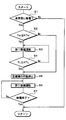
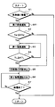
- control process shown in the flowchart of FIG. 3 is executed at predetermined intervals as a subroutine of the above-described main routine control process. Further, each control step in the flowchart of FIG. 3 constitutes various function realizing units included in the control device 50.
- step S1 it is determined whether or not frost formation has occurred in the air heat exchanger 24.
- the temperature difference (Tam ⁇ TL) obtained by subtracting the low-pressure refrigerant temperature TL detected by the low-pressure refrigerant temperature sensor 52 from the outside air temperature Tam is equal to or greater than a predetermined reference temperature difference. It is determined that frost formation has occurred in the air heat exchanger 24. Therefore, control step S1 comprises the frost determination part.
- step S1 of this embodiment in order to determine whether or not the air heat exchanger 24 is actually frosted, are the operating conditions under which the air heat exchanger 24 can be frosted? It is determined whether or not. In other words, in Step S1, it can be expressed that it is determined whether or not there is a possibility that frost formation has occurred in the air heat exchanger 24.
- step S1 determines with the frost formation having arisen in the air heat exchanger 24 in step S1
- step S2 it progresses to step S2 and it is not determined with the frost formation having occurred in the air heat exchanger 24 Return to the main routine.
- step S2 it is determined whether or not the inflow air temperature Tai detected by the air temperature sensor 51 is equal to or lower than a predetermined reference inflow air temperature KTai.
- the reference inflow air temperature KTai is set to a temperature at which the air heat exchanger 24 can be quickly defrosted when the heat source air is led to the air heat exchanger 24 side.
- the air heat exchanger 24 can be quickly defrosted by guiding the heat source air to the air heat exchanger 24 side.
- the reference inflow air temperature KTai is set to 5 ° C.
- step S2 When it is determined in step S2 that the inflow air temperature Tai is equal to or lower than the reference inflow air temperature KTai, the process proceeds to step S3, where the inflow air temperature Tai is not lower than the reference inflow air temperature KTai. If it is determined, the process proceeds to step S5.
- step S3 the first defrosting operation is performed.
- the throttle opening of the electric expansion valve 23 is increased. More specifically, the throttle opening of the electric expansion valve 23 is fully opened.
- step S1 when it is determined in step S1 that frost formation has occurred in the state where the compressor 21 is operated, the air heat exchanger 24 is present.
- a refrigerant having a temperature higher than that of the low-pressure refrigerant (hereinafter, referred to as residual low-pressure refrigerant) flows into the air heat exchanger 24.
- the low-pressure refrigerant temperature TL is read again, and it is determined whether or not the read low-pressure refrigerant temperature TL is equal to or higher than a predetermined reference low-pressure refrigerant temperature KTL.
- the reference low-pressure refrigerant temperature KTL is set so that it can be confirmed that the low-pressure refrigerant in the air heat exchanger 24 is replaced with a high-temperature refrigerant.
- the reference low-pressure refrigerant temperature KTL is set to 0 ° C.
- step S4 When it is determined in step S4 that the low-pressure refrigerant temperature TL is equal to or higher than the reference low-pressure refrigerant temperature KTL, the process proceeds to step S5, and the low-pressure refrigerant temperature TL is not equal to or higher than the reference low-pressure refrigerant temperature KTL. When it is determined that, the process returns to step S3. In step S5, the operation of the compressor 21 is stopped, and the process proceeds to step S6.
- step S6 the second defrosting operation is executed.
- the heat source air introduction control unit 50c controls the operation of the heat pump side door 43 so that the heat pump side door 43 closes the outside air introduction port with the compressor 21 stopped. . Thereby, only exhaust gas is led to the air heat exchanger 24 side. In other words, the exhaust gas whose temperature has not decreased due to the mixing of outside air is guided to the air heat exchanger 24 side.
- step S7 the process returns to the main routine after the defrosting of the air heat exchanger 24 is completed.
- the process may return to the main routine after waiting for a predetermined waiting time Tx to complete the defrosting, or to return to the main routine.
- a temperature detection unit that detects the temperature of the heat exchanger 24 itself may be provided, and when the temperature of the air heat exchanger 24 itself becomes equal to or higher than the reference end temperature, the process may return to the main routine.
- the heating system 10 of the present embodiment it is determined that frost formation has occurred in the air heat exchanger 24 in step S1 that constitutes the frost determination unit, and the inflow air temperature Tai is the reference inflow air temperature KTai.
- the heat source air exhaust gas
- the frost attached to the air heat exchanger 24 is quickly melted by the heat of the heat source air (exhaust), and air heat exchange is performed. Rapid defrosting of the vessel 24 can be realized.
- step S1 when it is determined in step S1 that frost formation has occurred in the air heat exchanger 24, and when the inflow air temperature Tai is equal to or lower than the reference inflow air temperature KTai, the heat source air is air. Even if it leads to the heat exchanger 24 side, there is a possibility that rapid defrosting of the air heat exchanger 24 may not be realized due to the heat of the heat source air.
- the amount of heat necessary for completing the defrosting of the air heat exchanger 24 of the heat pump cycle 20 is not only the amount of heat necessary for melting the frost generated in the air heat exchanger 24 but also the air heat. An amount of heat for heating the main body of the exchanger 24 is also required.
- step S1 it is determined in step S1 that frost formation has occurred in the air heat exchanger 24, and when the inflow air temperature Tai is equal to or lower than the reference inflow air temperature KTai. Performs the second defrosting operation after executing the first defrosting operation.
- the refrigerant having a temperature higher than the residual low-pressure refrigerant is caused to flow into the air heat exchanger 24. Therefore, the refrigerant in the air heat exchanger 24 Can be replaced with a refrigerant having a temperature higher than that of the residual low-pressure refrigerant. Therefore, the amount of heat required to complete the defrosting of the air heat exchanger 24 can be reduced.
- the process moves to the second defrosting operation, so that the execution time of the first defrosting operation is not shortened.
- the refrigerant in the air heat exchanger 24 can be surely replaced with a refrigerant having a temperature higher than that of the residual low-pressure refrigerant without causing a long time to be required.
- the heat pump side door 43 closes the outside air inlet, so that outside air is mixed with the exhaust led to the air heat exchanger 24 side via the exhaust duct 40b. There is no end. Therefore, exhaust (heat source air) whose temperature has not decreased due to mixing of outside air can be guided to the air heat exchanger 24 side, and the air heat exchanger 24 can be efficiently defrosted.
- the defrost time is compared with the case where the heat source air is led to the air heat exchanger 24 without performing the first defrost operation. That is, it is possible to shorten the time from the start of the first defrosting operation to the completion of the defrosting of the air heat exchanger 24.
- the throttle opening degree of the electric expansion valve 23 is increased during the first defrosting operation, so that the refrigerant having a temperature higher than that of the residual low-pressure refrigerant is very easily converted to the air heat exchanger. 24.
- the heat medium heated by the heat pump cycle 20 is stored in the tank 31, and the heater core 34 heats the supply air using the heat medium stored in the tank 31 as a heat source. Therefore, even if the compressor 21 is stopped during the defrosting operation, the room heating can be continued by the heat of the heat medium stored in the tank 31.
- the heating system 10 of the present embodiment since the defrosting time can be shortened, the tank 31 having a small capacity can be adopted, and the heating system 10 as a whole can be downsized. Furthermore, since the heat source air (exhaust gas) of the present embodiment is air heated indirectly by the heat pump cycle 20 via the heat medium, it is surely higher in temperature than the residual low-pressure refrigerant during the second defrosting operation. The exhaust can be led to the air heat exchanger 24 side.
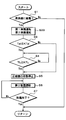
- This embodiment demonstrates the example which changed the content of the subroutine performed in order to perform a defrost operation with respect to 1st Embodiment, as shown to the flowchart of FIG. More specifically, in the present embodiment, after the first defrosting operation is executed in step S3, the elapsed time Ta from the start of the execution of the first defrosting operation is determined in advance in step S41. It is determined whether or not the elapsed time KTa has been reached.
- the reference elapsed time KTa is set so that the low-pressure refrigerant temperature TL becomes equal to or higher than the reference low-pressure refrigerant temperature KTL by waiting for the elapse of the reference elapsed time KTa from the start of the first defrosting operation.
- a reference elapsed time KTa may be a predetermined value experimentally obtained in advance or may be determined with reference to a control map stored in the control device 50 based on the outside air temperature Tam. .
- step S41 in FIG. 4 When it is determined in step S41 in FIG. 4 that the elapsed time Ta is equal to or greater than the reference elapsed time KTa, the process proceeds to step S5, and the elapsed time Ta is not equal to or greater than the reference elapsed time KTa. When it is determined, the process returns to step S3.
- Other configurations and operations are the same as those in the first embodiment. Therefore, also in the heating system 10 of this embodiment, the effect similar to 1st Embodiment can be acquired.
- step S4 demonstrated in 1st Embodiment
- step S41 low-pressure refrigerant
- coolant There is no need to read the temperature TL. Therefore, the low-pressure refrigerant temperature sensor 52 may be eliminated.
- step S1 constituting the frost determination unit air is discharged when the outside air temperature Tam is a predetermined reference frost temperature (for example, ⁇ 5 ° C. or lower). It may be determined that frost formation has occurred in the heat exchanger 24.
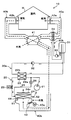
- the refrigerant on the upstream side of the electric expansion valve 23 of the heat pump cycle 20 is bypassed by the electric expansion valve 23 and is air
- a bypass passage 25 leading to the refrigerant inlet side of the heat exchanger 24 and an opening / closing valve 26 as an opening / closing portion for opening / closing the bypass passage 25 will be described.
- the on-off valve 26 is an electromagnetic valve that is opened and closed by a control voltage output from the control device 50.
- the control device 50 opens the on-off valve 26 so that a refrigerant having a temperature higher than that of the residual low-pressure refrigerant is caused to flow into the air heat exchanger 24.
- Other configurations and operations are the same as those in the first embodiment. Therefore, also in the heating system 10 of this embodiment, the effect similar to 1st Embodiment can be acquired.
- FIG. 5 shows an example in which the bypass passage 25 is arranged so as to guide the high-pressure refrigerant upstream of the water-refrigerant heat exchanger 22 to the refrigerant inlet side of the air heat exchanger 24.
- the bypass passage 25 may be arranged so that the high-pressure refrigerant on the downstream side of the water-refrigerant heat exchanger 22 is guided to the refrigerant inlet side of the air heat exchanger 24.
- the first defrosting operation and the second defrosting operation can be performed in order to defrost the air heat exchanger 24 of the heat pump cycle 20.
- coolant which mainly retains in the air heat exchanger 24 main body and the air heat exchanger 24 can be raised.
- frost can be melted mainly from the outside of the air heat exchanger 24.
- the defrosting of the air heat exchanger 24 is performed by changing the execution order of the first defrosting operation and the second defrosting operation, simultaneously executing the first defrosting operation and the second defrosting operation, or the like.
- defrosting control for completing the operation more quickly. Therefore, in this embodiment, as shown in the flowchart of FIG. 6, an example will be described in which the contents of a subroutine executed for performing the defrosting operation are changed with respect to the first embodiment.
- step S2 when it is determined in step S2 that the inflow air temperature Tai is equal to or lower than the reference inflow air temperature KTai, the process proceeds to step S31, where the inflow air temperature Tai is the reference air temperature Tai.
- step S5 When it is determined that the temperature is not lower than the inflow air temperature KTai, the process proceeds to step S5.
- step S31 both the first defrosting operation and the second defrosting operation are executed, and the process proceeds to step S4. That is, in step S31 of the present embodiment, the throttle opening of the electric expansion valve 23 is increased as the first defrosting operation without stopping the operation of the compressor 21. Furthermore, the operation of the heat pump side door 43 is controlled so that the heat pump side door 43 closes the outside air inlet as the second defrosting operation.
- step S4 when it is determined that the low-pressure refrigerant temperature TL is equal to or higher than the reference low-pressure refrigerant temperature KTL, the process proceeds to step S5, where it is determined that the low-pressure refrigerant temperature TL is not equal to or higher than the reference low-pressure refrigerant temperature KTL. If it happens, the process returns to step S31. In step S5, the operation of the compressor 21 is stopped, and the process proceeds to step S6.
- step S6 the second defrosting operation is executed as in the first embodiment. That is, in step S6, only the second defrosting operation is performed with the first defrosting operation stopped and the compressor 21 stopped. Other configurations and operations are the same as those in the first embodiment. Therefore, also in the heating system 10 of this embodiment, the effect similar to 1st Embodiment can be acquired.
- the temperature of the heat source air tends to be low.
- the power consumption during the defrosting operation is likely to increase only by performing only the first defrosting operation.
- the defrosting time becomes longer and the time during which the room cannot be heated tends to be longer.
- the first defrosting operation and the second defrosting operation are performed simultaneously.
- the first defrosting operation can be executed mainly to heat the temperature of the refrigerant in the air heat exchanger 24 main body and the air heat exchanger 24 to 0 ° C. or higher.
- the second defrosting operation can be performed mainly to melt the frost that has arrived at the air heat exchanger 24. Therefore, the amount of heat necessary for melting the frost and the amount of heat necessary for heating the low-pressure refrigerant staying in the air heat exchanger 24 can be quickly secured.
- the defrosting time (that is, the time from the start of the first and second defrosting operations until the defrosting of the air heat exchanger 24 is completed) is further increased. It can be further shortened.
- the operation time of the compressor 21 can be shortened as compared with the case where only the first defrosting operation is executed in the control step S31. Therefore, the power consumption of the compressor 21 consumed for defrosting the air heat exchanger 24 can be reduced.
- step S ⁇ b> 1 when it is determined in step S ⁇ b> 1 that frost formation has occurred in the air heat exchanger 24, the process proceeds to step S ⁇ b> 32 and frost formation has occurred in the air heat exchanger 24. If it is not determined that it has occurred, the process returns to the main routine.
- step S32 the first defrosting operation is performed. That is, in step S32, the throttle opening of the electric expansion valve 23 is increased as the first defrosting operation without stopping the operation of the compressor 21.
- step S2 when it is determined that the inflow air temperature Tai is equal to or lower than the reference inflow air temperature KTai, the process proceeds to step S4. If so, the process proceeds to step S5. In step S4, the process waits for the low-pressure refrigerant temperature TL to be equal to or higher than the reference low-pressure refrigerant temperature KTL, and then proceeds to step S5.
- step S5 the process waits for the low-pressure refrigerant temperature TL to be equal to or higher than the reference low-pressure refrigerant temperature KTL, and then proceeds to step S5.
- Other configurations and operations are the same as those in the first embodiment.
- the defrosting time can be shortened as in the first embodiment.
- step S ⁇ b> 1 when it is determined in step S ⁇ b> 1 that frost formation has occurred in the air heat exchanger 24, the process proceeds to step S ⁇ b> 61 and frost formation has occurred in the air heat exchanger 24. If it is not determined that it has occurred, the process returns to the main routine.
- step S61 the second defrosting operation is performed. That is, in step S61, the operation of the heat pump side door 43 is controlled so that the heat pump side door 43 closes the outside air inlet as the second defrosting operation without stopping the operation of the compressor 21.
- step S2 The control after step S2 is the same as in the first embodiment. For this reason, in step S3 of this embodiment, both a 1st defrost operation and a 2nd defrost operation are performed. In Step 6, only the second defrosting operation is executed. Other configurations and operations are the same as those in the first embodiment.
- the defrosting time can be shortened as in the first embodiment. Furthermore, in this embodiment, when it determines with the frost formation of the air heat exchanger 24 having arisen, since a 2nd defrost operation is started, the temperature of heat-source air can be raised, and more defrost Time can be shortened.
- step S ⁇ b> 1 when it is determined in step S ⁇ b> 1 that frost formation has occurred in the air heat exchanger 24, the process proceeds to step S ⁇ b> 33 and frost formation has occurred in the air heat exchanger 24. If it is not determined that it has occurred, the process returns to the main routine.
- step S33 both the first defrosting operation and the second defrosting operation are performed. That is, in step S33 of the present embodiment, the throttle opening of the electric expansion valve 23 is increased as the first defrosting operation without stopping the operation of the compressor 21. Furthermore, the operation of the heat pump side door 43 is controlled so that the heat pump side door 43 closes the outside air inlet as the second defrosting operation.
- step S2 when it is determined that the inflow air temperature Tai is equal to or lower than the reference inflow air temperature KTai, the process proceeds to step S4. If so, the process proceeds to step S5. In step S4, the process waits for the low-pressure refrigerant temperature TL to be equal to or higher than the reference low-pressure refrigerant temperature KTL, and then proceeds to step S5.
- step S6 the second defrosting operation is executed as in the first embodiment. That is, in step S6, only the second defrosting operation is performed with the first defrosting operation stopped and the compressor 21 stopped. Other configurations and operations are the same as those in the first embodiment.
- the defrosting time can be shortened as in the first embodiment.
- step S41 when the first defrosting operation and the second defrosting operation are executed in step S31, the process proceeds to step S41.
- step S41 as in the second embodiment, it is determined whether or not the elapsed time Ta from the start of execution of the first defrosting operation is equal to or greater than a predetermined reference elapsed time KTa.
- step S41 When it is determined in step S41 that the elapsed time Ta is equal to or greater than the reference elapsed time KTa, the process proceeds to step S5, and it is determined that the elapsed time Ta is not equal to or greater than the reference elapsed time KTa. In this case, the process returns to step S31.
- Other configurations and operations are the same as those in the fourth embodiment. Therefore, also in the heating system 10 of this embodiment, the effect similar to 4th Embodiment can be acquired.
- step S2 when it is determined in step S2 that the inflow air temperature Tai is equal to or lower than the reference inflow air temperature KTai, the process proceeds to step S41.
- step S41 the process waits for the elapsed time Ta to be equal to or longer than the reference elapsed time KTa, and then proceeds to step S5.
- Other configurations and operations are the same as those of the fifth embodiment.
- the defrosting time can be shortened as in the fifth embodiment.
- step S41 when the first defrosting operation is executed in step S3, the process proceeds to step S41.
- step S41 as in the second embodiment, as in the second embodiment, it is determined whether or not the elapsed time Ta from the start of the execution of the first defrosting operation is equal to or greater than a predetermined reference elapsed time KTa. To do.
- step S41 When it is determined in step S41 that the elapsed time Ta is equal to or greater than the reference elapsed time KTa, the process proceeds to step S5, and it is determined that the elapsed time Ta is not equal to or greater than the reference elapsed time KTa. In this case, the process returns to step S3.
- Other configurations and operations are the same as those in the sixth embodiment. Therefore, also in the heating system 10 of the present embodiment, the same effect as in the sixth embodiment can be obtained.
- Embodiment demonstrates the example which changed the content of the subroutine performed in order to perform a defrost operation as shown in the flowchart of FIG. 13 with respect to 7th Embodiment.
- step S2 when it is determined in step S2 that the inflow air temperature Tai is equal to or lower than the reference inflow air temperature KTai, the process proceeds to step S41.
- step S41 the process waits for the elapsed time Ta to be equal to or longer than the reference elapsed time KTa, and then proceeds to step S5.
- Other configurations and operations are the same as those of the seventh embodiment.
- the defrosting time can be shortened as in the fifth embodiment.
- the present invention may be applied to a heat pump water heater in which hot water is heated by the water-refrigerant heat exchanger 22 and the heated hot water is supplied to a bathtub or a kitchen.
- the heater core 34 of the above-described embodiment can be eliminated.
- hot water supply water may be adopted as the heating target fluid of the heat pump cycle 20 instead of the antifreeze liquid, and the hot water stored in the tank 31 may be supplied to a bathtub or a kitchen.
- the present invention may be applied to a heating system that heats blown air by exchanging heat between the high-pressure refrigerant discharged from the compressor 21 and blown air blown into the room.
- the heating terminal that uses the heat of the heat medium as a heat source is not limited thereto.
- the heating medium heated by the water-refrigerant heat exchanger 22 may be directly supplied to these heating terminals.
- the tank 31 can be disposed.
- the component apparatus which comprises a heat pump apparatus (heating system 10) is not limited to what was disclosed by the above-mentioned embodiment.
- an electric compressor is adopted as the compressor 21
- the compressor 21 is not limited thereto.
- an engine-driven compressor driven by a rotational driving force transmitted from an internal combustion engine (engine) via a pulley, a belt, or the like may be employed as the compressor.
- a variable capacity compressor that can adjust the refrigerant discharge capacity by changing the discharge capacity can be adopted.
- the ventilation heat exchanger 41 a so-called total heat exchanger configured by laminating and arranging plate-like members formed of a material having heat conductivity and moisture permeability may be adopted. In such a total heat exchanger, not only temperature but also humidity can be exchanged between exhaust and supply air.
- step S1 constituting the frost determination unit are not limited to the conditions disclosed in the above-described embodiment. For example, it may be determined that frost formation has occurred in the air heat exchanger 24 when the low-pressure refrigerant temperature TL is equal to or lower than a predetermined reference low-pressure refrigerant temperature.
- frost formation has occurred after a predetermined operating time has elapsed. Further, it may be determined that frosting has occurred when the tank 31 is full and the heat pump cycle 20 is stopped. This is because the time when the tank 31 is full can be predicted in advance, so that when the tank 31 is full, it can be considered that a predetermined operation time has elapsed.
- the part that causes the refrigerant having a temperature higher than the residual low-pressure refrigerant to flow into the air heat exchanger 24 during the first defrosting operation is not limited to that disclosed in the above-described embodiment.
- the compressor 21 ⁇ water-refrigerant heat exchanger 22 ⁇ electric expansion valve 23 ⁇ air heat exchanger 24 ⁇ compressor 21 is switched to a refrigerant circuit that circulates refrigerant in this order.
- a refrigerant circuit switching unit (such as a four-way valve) that switches to a refrigerant circuit that circulates the refrigerant in the order of the machine 21 ⁇ the air heat exchanger 24 ⁇ the electric expansion valve 23 ⁇ the compressor 21 is employed, and the refrigerant has a higher temperature than the residual low-pressure refrigerant. May be allowed to flow into the air heat exchanger 24.
- only exhaust gas can be guided to the air heat exchanger 24 side, or only outside air can be guided to the air heat exchanger 24 side.
- the mixing ratio of the exhaust and the outside air in the air guided to the air heat exchanger 24 side can be adjusted.
- control processing described in the second and fourth to eleventh embodiments may be applied to the heating system 10 having the configuration described in the third embodiment.
Landscapes
- Engineering & Computer Science (AREA)
- Physics & Mathematics (AREA)
- Mechanical Engineering (AREA)
- Thermal Sciences (AREA)
- General Engineering & Computer Science (AREA)
- Chemical & Material Sciences (AREA)
- Combustion & Propulsion (AREA)
- Central Heating Systems (AREA)
- Heat-Pump Type And Storage Water Heaters (AREA)
Abstract
ヒートポンプ装置は、冷媒を蒸発させる蒸発器(24)を有するヒートポンプサイクル(20)と、外気よりも高温の熱源空気を前記蒸発器側へ導く熱源空気導入部(40b)と、前記蒸発器に着霜が生じているか否かを判定する着霜判定部(S1)と、前記着霜判定部によって前記蒸発器に着霜が生じていると判定された際に、前記蒸発器の除霜を行うための除霜運転を実行する制御部(50)を備える。制御部は、前記除霜運転として、前記着霜判定部によって前記蒸発器に着霜が生じていると判定された際の前記低圧冷媒よりも高温の冷媒を前記蒸発器へ流入させる第1除霜運転、および前記熱源空気導入部によって前記熱源空気を前記蒸発器側へ導く第2除霜運転を実行可能である。
Description
本出願は、2014年6月19日に出願された日本出願番号2014-126234号と2015年6月2日に出願された日本出願番号2015-111931号に基づくもので、ここにそれらの記載内容を援用する。
本開示は、ヒートポンプサイクルの蒸発器に着霜が生じた際に、除霜するための除霜運転を行うヒートポンプ装置に関する。
従来、ヒートポンプサイクル(蒸気圧縮式の冷凍サイクル)を備え、このヒートポンプサイクルの蒸発器に着霜が生じた際に、除霜するための除霜運転を行うヒートポンプ装置が知られている。例えば、特許文献1には、この種のヒートポンプ装置として、ヒートポンプサイクルの放熱器にて温室内の空気を加熱し、温室内の暖房を行う暖房システムが開示されている。
さらに、この特許文献1のヒートポンプ装置(暖房システム)では、温室内の空気を蒸発器側へ導くダクトを備えており、蒸発器に着霜が生じた際に、ヒートポンプサイクルの圧縮機を停止させた状態で、ダクトを介して換気のために温室内から排出された空気(排気)を蒸発器側へ導くことによって除霜運転を行っている。
ところが、特許文献1のヒートポンプ装置のように、排気を蒸発器側へ導くことによって除霜運転を行う構成では、排気の温度や湿度が変化してしまうと、除霜運転の開始から蒸発器の除霜を完了するまでの除霜時間も変化してしまう。つまり、排気の温度や湿度が低下してしまうと、除霜時間が長くなってしまう。
さらに、特許文献1のヒートポンプ装置のように、除霜運転の実行中にヒートポンプサイクルの圧縮機を停止させてしまう構成では、除霜時間が長くなってしまうと、温室内の暖房を行うことができない時間も長くなってしまう。
本開示は、上記点に鑑み、除霜運転を行うヒートポンプ装置において、除霜時間の短縮化を図ることを目的とする。
本開示は、以下に説明する知見に基づいて案出されたものである。すなわち、ヒートポンプサイクルの蒸発器の除霜を完了させるために必要な熱量は、単に、蒸発器に生じた霜を融解するために必要な熱量だけでなく、蒸発器本体等を加熱するための熱量も必要となる。
さらに、本発明者が、蒸発器の除霜を完了させるために必要な熱量についてより詳細に調査したところ、蒸発器本体等を加熱するために必要な熱量のうち、蒸発器内に滞留している低圧冷媒を加熱するために必要な熱量の割合が多いことが判った。
本開示の一態様において、ヒートポンプ装置は、ヒートポンプサイクルと、熱源空気導入部と、着霜判定部と、制御部を備える。ヒートポンプサイクルは、冷媒を圧縮して吐出する圧縮機、圧縮機から吐出された高圧冷媒と加熱対象流体とを熱交換させる放熱器、放熱器から流出した冷媒を減圧させる減圧部、および減圧部にて減圧された低圧冷媒と空気とを熱交換させて低圧冷媒を蒸発させる蒸発器を有する。熱源空気導入部は、外気よりも高温の熱源空気を蒸発器側へ導く。着霜判定部は、蒸発器に着霜が生じているか否かを判定する。制御部は、着霜判定部によって蒸発器に着霜が生じていると判定された際に、蒸発器の除霜を行うための除霜運転を実行する。制御部は、除霜運転として、着霜判定部によって蒸発器に着霜が生じていると判定された際の低圧冷媒よりも高温の冷媒を蒸発器へ流入させる第1除霜運転、および熱源空気導入部によって前記熱源空気を前記蒸発器側へ導く第2除霜運転を実行可能である。
これによれば、第1除霜運転および第2除霜運転を実行可能に構成されているので、蒸発器の除霜時に必要とされる、蒸発器内に滞留している低圧冷媒を加熱するために必要な熱量、および霜を融解するために必要な熱量を、容易に確保することができる。
より詳細には、第1除霜運転では、低圧冷媒よりも高温の冷媒を蒸発器へ流入させるので、蒸発器内の冷媒を低圧冷媒よりも高温の冷媒に置換して、主に蒸発器本体および蒸発器内に滞留する冷媒の温度を上昇させることができる。また、第2除霜運転では、熱源空気導入部によって熱源空気を蒸発器側へ導くので、主に蒸発器の外部から霜を融解することができる。
従って、蒸発器の除霜時に必要とされる熱量を容易に確保することができ、除霜時間(すなわち、第1、第2除霜運転の開始から、蒸発器の除霜を完了するまでの時間)の短縮化を図ることができる。
さらに、第1除霜運転および第2除霜運転の実行順序を変更することや、第1除霜運転および第2除霜運転を同時に実行すること等によって、蒸発器の除霜を速やかに完了させるための除霜制御を実現しやすい。
ヒートポンプ装置は、蒸発器にて低圧冷媒と熱交換する空気の流入空気温度を検出する空気温度検出部をさらに備えてもよい。着霜判定部によって蒸発器に着霜が生じていると判定され、さらに、空気温度検出部によって検出された流入空気温度が予め定めた基準流入空気温度以下になっている際には、圧縮機を作動させた状態で、第1除霜運転および第2除霜運転の双方を実行してもよい。
ヒートポンプ装置は、蒸発器から流出した冷媒の低圧冷媒温度を検出する冷媒温度検出部をさらに備えてもよい。第1除霜運転および第2除霜運転の双方が実行されている際に、さらに、低圧冷媒温度が予め定めた基準低圧冷媒温度以上となった際には、第1除霜運転を停止し、圧縮機を停止させた状態で、第2除霜運転のみを実行するようにしてもよい。
本開示の一態様において、ヒートポンプ装置は、ヒートポンプサイクルと、熱源空気導入部と、空気温度検出部と、冷媒温度検出部と、着霜判定部と、制御部を備える。ヒートポンプサイクルは、冷媒を圧縮して吐出する圧縮機、圧縮機から吐出された高圧冷媒と加熱対象流体とを熱交換させる放熱器、放熱器から流出した冷媒を減圧させる減圧部、および減圧部にて減圧された低圧冷媒と空気とを熱交換させて低圧冷媒を蒸発させる蒸発器を有する。熱源空気導入は、外気よりも高温の熱源空気を蒸発器側へ導く。空気温度検出部は、蒸発器にて低圧冷媒と熱交換する空気の流入空気温度を検出する。冷媒温度検出部は、蒸発器から流出した冷媒の低圧冷媒温度を検出する。着霜判定部は、蒸発器に着霜が生じているか否かを判定する。制御部は、着霜判定部によって蒸発器に着霜が生じていると判定され、さらに、空気温度検出部によって検出された流入空気温度が予め定めた基準流入空気温度以下になっている際には、圧縮機を作動させた状態で、着霜判定部によって蒸発器に着霜が生じていると判定された際の低圧冷媒よりも高温の冷媒を蒸発器へ流入させる第1除霜運転を実行する。さらに、制御部は、第1除霜運転の実行中に、低圧冷媒温度が予め定めた基準低圧冷媒温度以上となった際には、圧縮機を停止させた状態で、熱源空気導入部によって熱源空気を蒸発器側へ導く第2除霜運転を実行する。
これによれば、第1除霜運転時に、低圧冷媒よりも高温の冷媒を蒸発器へ流入させるので、蒸発器内の冷媒を低圧冷媒よりも高温の冷媒に置換することができる。従って、蒸発器の除霜を完了させるために必要な熱量を低減させることができる。
さらに、第1除霜運転の実行中に、低圧冷媒温度が予め定めた基準低圧冷媒温度以上となった際には、第2除霜運転へ移行するので、第1除霜運転の実行時間を不必要に長時間化させてしまうことなく、蒸発器内の冷媒を確実に低圧冷媒よりも高温の冷媒に置き換えることができる。
これに加えて、第2除霜運転時に、熱源空気導入部によって熱源空気を蒸発器側へ導くので、蒸発器の効率的に除霜を行うことができる。その結果、除霜時間(すなわち、第1、第2除霜運転の開始から、蒸発器の除霜を完了するまでの時間)の短縮化を図ることができる。
本開示の一態様において、ヒートポンプ装置は、ヒートポンプサイクルと、熱源空気導入部と、空気温度検出部と、着霜判定部と、制御部を備える。ヒートポンプサイクルは、冷媒を圧縮して吐出する圧縮機、圧縮機から吐出された高圧冷媒と加熱対象流体とを熱交換させる放熱器、放熱器から流出した冷媒を減圧させる減圧部、および減圧部にて減圧された低圧冷媒と空気とを熱交換させて低圧冷媒を蒸発させる蒸発器を有する。熱源空気導入部は、外気よりも高温の熱源空気を蒸発器側へ導く。空気温度検出部は、熱源空気導入部から蒸発器側へ導かれる熱源空気の流入空気温度を検出する。着霜判定部は、蒸発器に着霜が生じているか否かを判定する。制御部は、着霜判定部によって蒸発器に着霜が生じていると判定され、さらに、空気温度検出部によって検出された流入空気温度が予め定めた基準流入空気温度以下になっている際には、圧縮機を作動させた状態で、着霜判定部によって蒸発器に着霜が生じていると判定された際の低圧冷媒よりも高温の冷媒を蒸発器へ流入させる第1除霜運転を実行する。さらに、制御部は、第1除霜運転の実行開始から予め定めた基準経過時間を経過した際には、圧縮機を停止させた状態で、熱源空気導入部によって熱源空気を蒸発器側へ導く第2除霜運転を実行する。
これによれば、第1除霜運転時に、低圧冷媒よりも高温の冷媒を蒸発器へ流入させるので、蒸発器の除霜を完了させるために必要な熱量を低減させることができる。さらに、第1除霜運転の実行開始から予め定めた既定時間を経過した際には、第2除霜運転へ移行するので、第1除霜運転の実行時間を不必要に長時間化させてしまうことがない。
これに加えて、第2除霜運転時に、熱源空気を蒸発器側へ導くように熱源空気導入部を作動させるので、蒸発器の除霜を効率的に行うことができる。その結果、除霜時間の短縮化を図ることができる。
着霜判定部は、実際に蒸発器に着霜が生じているか否かを判定する判定部に限定されることなく、蒸発器に着霜が生じ得る運転条件であるか否かを判定する判定部や、蒸発器に着霜が生じている可能性があるか否かを判定する判定部を含む。
また、熱源空気導入部は、少なくとも第2除霜運転時に熱源空気を蒸発器側へ導くことができれば、他の運転時に熱源空気を蒸発器側へ導くものであってもよい。
本開示についての上記およびその他の目的、特徴や利点は、添付の図面を参照しながら下記の詳細な記述により、より明確になる。
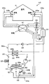
第1実施形態の暖房システムの全体構成図である。
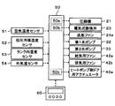
第1実施形態の暖房システムの電気制御部を示すブロック図である。
第1実施形態の暖房システムの制御処理を示すフローチャートである。
第2実施形態の暖房システムの制御処理を示すフローチャートである。
第3実施形態の暖房システムの全体構成図である。
第4実施形態の暖房システムの制御処理を示すフローチャートである。
第5実施形態の暖房システムの制御処理を示すフローチャートである。
第6実施形態の暖房システムの制御処理を示すフローチャートである。
第7実施形態の暖房システムの制御処理を示すフローチャートである。
第8実施形態の暖房システムの制御処理を示すフローチャートである。
第9実施形態の暖房システムの制御処理を示すフローチャートである。
第10実施形態の暖房システムの制御処理を示すフローチャートである。
第11実施形態の暖房システムの制御処理を示すフローチャートである。
(第1実施形態)
図1~図3を用いて、第1実施形態について説明する。本実施形態では、ヒートポンプ装置を、図1に示す暖房システム10に適用している。
図1~図3を用いて、第1実施形態について説明する。本実施形態では、ヒートポンプ装置を、図1に示す暖房システム10に適用している。
この暖房システム10は、ヒートポンプサイクル(蒸気圧縮式の冷凍サイクル)20、第1、第2水循環回路30a、30b、給気ダクト40a、排気ダクト40b等を備えている。そして、ヒートポンプサイクル20にて第1、第2水循環回路30a、30bを循環する熱媒体を加熱し、加熱された熱媒体を熱源として家屋Hの室内へ送風される送風空気を加熱する構成になっている。
まず、ヒートポンプサイクル20について説明する。本実施形態のヒートポンプサイクル20は、後述する第1水循環回路30aを循環する熱媒体を加熱する機能を果たす。従って、熱媒体は、ヒートポンプサイクル20の加熱対象流体である。ヒートポンプサイクル20は、圧縮機21、水-冷媒熱交換器22、電気式膨張弁23、および空気熱交換器24を冷媒配管で接続して構成されている。
また、本実施形態のヒートポンプサイクル20では、冷媒として二酸化炭素を採用しており、圧縮機21の吐出口側から電気式膨張弁23の入口側へ至るサイクルの高圧冷媒の圧力が冷媒の臨界圧力以上となる超臨界冷凍サイクルを構成している。さらに、冷媒には圧縮機21を潤滑するための冷凍機油が混入されており、冷凍機油の一部は冷媒とともにサイクルを循環している。
圧縮機21は、ヒートポンプサイクル20において冷媒を吸入し、臨界圧力以上となるまで圧縮して吐出するもので、吐出容量が固定された固定容量型圧縮機構を電動モータにて駆動する電動圧縮機である。固定容量型圧縮機構としては、具体的に、スクロール型圧縮機構、ベーン型圧縮機構等の各種圧縮機構を採用することができる。
電動モータは、後述する制御装置50から出力される制御信号によって、その回転数が制御されるもので、交流モータ、直流モータのいずれの形式を採用してもよい。そして、この回転数制御によって、圧縮機21の冷媒吐出能力が変更される。圧縮機21の吐出口には、水-冷媒熱交換器22の冷媒通路22a入口側が接続されている。
水-冷媒熱交換器22は、圧縮機21から吐出された高圧冷媒を流通させる冷媒通路22a、および第1水循環回路30aを循環する熱媒体を流通させる水通路22bを有し、冷媒通路22aを流通する高圧冷媒と水通路22bを流通する熱媒体とを熱交換させて、熱媒体を加熱する放熱器である。
このような水-冷媒熱交換器22としては、冷媒通路22aの内周に水通路22bを配置して冷媒と冷却水とを熱交換させる構成や、冷媒通路22aとして冷媒を流通させる蛇行状のチューブあるいは複数本のチューブを採用し、隣り合うチューブ間に水通路22bを形成して冷媒と冷却水とを熱交換させる構成のものを採用することができる。
さらに、本実施形態では、水-冷媒熱交換器22として、冷媒通路22aを流通する冷媒の流れ方向と水通路22bを流通する熱媒体の流れ方向が対向流となる対向流型の熱交換器を採用している。
また、本実施形態のヒートポンプサイクル20は、前述の如く、超臨界冷凍サイクルを構成しているので、水-冷媒熱交換器22の冷媒通路22aでは、冷媒は凝縮することなく超臨界状態のまま放熱する。水-冷媒熱交換器22の冷媒通路22a出口側には、電気式膨張弁23の入口側が接続されている。
電気式膨張弁23は、水-冷媒熱交換器22の冷媒通路22aから流出した冷媒を減圧させる減圧部である。より具体的には、電気式膨張弁23は、絞り開度を変更可能に構成された弁体、および弁体を変位させて絞り開度を変化させる電動アクチュエータを有する可変絞り機構で構成されている。
さらに、電気式膨張弁23は、制御装置50から出力される制御信号によって、その作動が制御される。電気式膨張弁23の出口側には、空気熱交換器24の冷媒入口側が接続されている。
空気熱交換器24は、電気式膨張弁23にて減圧された低圧冷媒と送風ファン24aから送風された空気とを熱交換させて、低圧冷媒を蒸発させて吸熱作用を発揮させる蒸発器である。空気熱交換器24の冷媒出口には、圧縮機21の吸入口側が接続されている。また、送風ファン24aは、制御装置50から出力される制御電圧によって回転数(送風能力)が制御される電動送風機である。
これらのヒートポンプサイクル20の各構成機器21~24、24aは、1つの筐体内に収容されており、ヒートポンプユニットとして一体的に構成されている。さらに、このヒートポンプユニットは、室内に配置されている。なお、図1では、図示の明確化のために、ヒートポンプサイクル20の各構成機器21~24、24a等を家屋Hと異なる位置に示している。このことは、後述する図5においても同様である。
次に、第1、第2水循環回路30a、30bについて説明する。第1水循環回路30aは、水-冷媒熱交換器22の水通路22bとタンク31との間で熱媒体を循環させる熱媒体循環回路である。本実施形態では、熱媒体として、エチレングリコール水溶液からなる不凍液を採用している。この他にも、熱媒体として、水を採用してもよい。タンク31は、水-冷媒熱交換器22にて加熱された熱媒体を貯留する熱媒体貯留部である。
より具体的には、タンク31は、耐食性に優れた金属(例えば、ステンレス)にて中空円柱状に形成され、軸方向が略鉛直方向に延びる縦長形状に形成されている。さらに、タンク31は、外周を断熱材で覆う断熱構造あるいは二重タンクによる真空断熱構造等を有しており、高温の熱媒体を長時間保温しながら貯留することができる。なお、タンク31は、前述したヒートポンプユニットとともに、室内に配置されている。
また、第1水循環回路30aには、タンク31の下方側の熱媒体を吸入して水-冷媒熱交換器22の水通路22bへ圧送する第1水ポンプ32が配置されている。第1水ポンプ32は、制御装置50から出力される制御電圧によって回転数(水圧送能力)が制御される電動ポンプである。
そして、制御装置50が第1水ポンプ32を作動させると、タンク31の下方側の熱媒体が第1水ポンプ32→水-冷媒熱交換器22の水通路22b→タンク31の上方側の順に流れる。このため、タンク31内の熱媒体には、上方側から下方側へ向かって、温度が徐々に低下する温度分布が生じやすい。
第2水循環回路30bは、タンク31とヒータコア34との間で熱媒体を循環させる熱媒体循環回路である。ヒータコア34は、給気ダクト40a内の空気通路に配置されており、室内へ送風される送風空気と熱媒体とを熱交換させて送風空気を加熱する加熱用の熱交換器である。
また、第2水循環回路30bには、ヒータコア34から流出した熱媒体を吸入してタンク31の下方側へ圧送する第2水ポンプ33が配置されている。第2水ポンプ33の基本的構成は、第1水ポンプ32と同様である。そして、制御装置50が第2水ポンプ33を作動させると、タンク31の上方側の高温の熱媒体がヒータコア34→第2水ポンプ33→タンク31の下方側の順に流れる。
次に、給気ダクト40aおよび排気ダクト40bについて説明する。給気ダクト40aは、室内へ送風される送風空気(給気)を流通させる空気通路を形成する通風管であり、排気ダクト40bは、換気のために室内から排出される送風空気(排気)を流通させる空気通路を形成する通風管である。
このような給気ダクト40aおよび排気ダクト40bとしては、金属製のものを採用してもよいし、樹脂製のものを採用してもよい。さらに、内部を流通する送風空気と外部との断熱性を有する採用することが好ましい。
給気ダクト40aの空気流れ最上流側には、換気熱交換器41の給気用通路が接続されている。また、排気ダクト40bには、換気熱交換器41の排気用通路が接続されている。換気熱交換器41は、室内の換気を行う際に、給気用通路を流通する給気と排気用通路を流通する排気とを熱交換させる熱交換器である。
従って、換気熱交換器41では、暖房システム10の作動時に、高温の排気(室内から排出された空気)と低温の給気(室外から吸入される外気)とを熱交換させて、給気(外気)を加熱することができる。つまり、換気熱交換器41は、暖房システム10の作動時に、暖房時に排気とともに室外へ排出されてしまう熱エネルギを回収して給気を加熱することで、換気による室内の温度低下を抑制する機能を果たす。
このような換気熱交換器41としては、伝熱性に優れる複数の金属板(例えば、アルミニウム板や銅板)の板面同士を互いに平行に積層配置し、隣り合う金属板間に排気用通路と吸気通路とを交互に形成し、それぞれの排気用通路および給気用通路の内部に排気と給気との熱交換を促進するインナーフィンを配置することによって構成された熱交換器等を採用することができる。
また、給気ダクト40a内の空気通路には、換気熱交換器41を介して空気通路内へ導入された外気を、給気として室内に向けて送風する給気ファン42aが配置されている。給気ファン42aは、換気熱交換器41を介して制御装置50から出力される制御電圧によって回転数(送風能力)が制御される電動送風機である。
一方、排気ダクト40b内の空気通路には、換気のために室内から排出された排気を、換気熱交換器41の排気用通路へ向けて送風する排気ファン42bが配置されている。排気ファン42bの基本的構成は、給気ファン42aと同様である。なお、図1では、給気や排気の流れを太破線矢印で示している。
ここで、本実施形態では、図1に示すように、給気ダクト40a内の空気通路のうち、ヒータコア34の空気流れ下流側に給気ファン42aを配置しているが、もちろん、ヒータコア34の空気流れ上流側や換気熱交換器41の給気用通路の空気流れ上流側に給気ファン42aを配置してもよい。
同様に、本実施形態では、排気ダクト40b内の空気通路のうち、換気熱交換器41の排気用通路の空気流れ上流側に排気ファン42bを配置しているが、もちろん、換気熱交換器41の排気用通路の空気流れ下流側に排気ファン42bを配置してもよい。
また、排気ダクト40bの空気流れ最下流側には、排気をヒートポンプサイクル20の空気熱交換器24側へ向けて排出するヒートポンプ側排気口44が設けられている。さらに、排気ダクト40bの空気流れ最下流側には、外気を空気熱交換器24側へ導入する外気導入口が設けられている。この外気導入口には、外気導入口を開閉するヒートポンプ側ドア43が配置されている。
ヒートポンプ側ドア43は、ヒートポンプ側ドア駆動用の電動式のアクチュエータ43aによって駆動される。このアクチュエータ43aは、制御装置50から出力される制御信号によって、その作動が制御される。
そして、制御装置50が、外気導入口を開くように(図1の実線で示す位置に)ヒートポンプ側ドア43の作動を制御した際には、外気と排気との混合気体が空気熱交換器24側へ導かれる。一方、制御装置50が、外気導入口を閉じるように(図1の細破線で示す位置に)ヒートポンプ側ドア43の作動を制御した際には、排気に外気が混ざり合うことなく排気のみが空気熱交換器24側へ導かれる。
ここで、暖房システム10では、室内の空気温度が外気よりも高い温度となるように給気を加熱するので、排気は外気よりも高い温度となる。従って、本実施形態の排気は、熱源空気に対応しており、さらに、本実施形態の排気ダクト40bは、熱源空気導入部を構成している。
次に、図2のブロック図を用いて、本実施形態の暖房システム10の電気制御部の概要について説明する。制御装置50は、CPU、ROMおよびRAM等を含む周知のマイクロコンピュータとその周辺回路から構成されている。そして、そのROM内に記憶された制御プログラムに基づいて各種演算、処理を行い、その出力側に接続された各種制御対象機器の作動を制御する。
制御装置50の出力側には、ヒートポンプサイクル20の圧縮機21の電動モータ、電気式膨張弁23、送風ファン24a、第1水ポンプ32、第2水ポンプ33、給気ファン42a、排気ファン42b、ヒートポンプ側ドア駆動用のアクチュエータ43a等の各種制御対象機器が接続されている。
一方、制御装置50の入力側には、空気熱交換器24へ導かれる空気の温度(すなわち、空気熱交換器24にて低圧冷媒と熱交換する空気の流入空気温度)Taiを検出する空気温度検出部としての空気温度センサ51、空気熱交換器24から流出した直後の冷媒の温度(低圧冷媒温度)TLを検出する冷媒温度検出部としての低圧冷媒温度センサ52、タンク31内の熱媒体温度を検出するタンク内温度センサ53、外気温を検出する外気温センサ54等が接続されており、これらのセンサ群の検出信号が制御装置50に入力される。
さらに、制御装置50の入力側には、室内に配置されたリモコン(操作パネル)60が接続されている。このリモコン60には、暖房システム10の作動を要求する作動要求信号および停止を要求する停止要求信号を出力する作動スイッチ、室内の目標室内温度Tsetを設定する温度設定スイッチ、室内への目標風量Qaを設定する風量設定スイッチ等が設けられており、これらのスイッチの操作信号が制御装置50へ入力される。
ここで、本実施形態の制御装置50は、その出力側に接続された各種制御対象機器を制御する制御部が一体的に構成されたものであるが、制御装置50のうちそれぞれの制御対象機器の作動を制御する構成(ハードウェアおよびソフトウェア)が、それぞれの制御対象機器の作動を制御する制御部を構成している。
例えば、制御装置50のうち、ヒートポンプサイクルの圧縮機21の冷媒吐出能力(回転数)を制御する構成(ハードウェアおよびソフトウェア)が、吐出能力制御部50aを構成し、電気式膨張弁23の絞り開度を制御する構成が、絞り開度制御部50bを構成し、ヒートポンプ側ドア43(具体的には、ヒートポンプ側ドア駆動用のアクチュエータ43a)の作動を制御する構成が、熱源空気導入制御部50cを構成している。
さらに、吐出能力制御部50a、絞り開度制御部50b、熱源空気導入制御部50c等を制御装置50に対して別の装置で構成してもよい。
次に、上記構成における本実施形態の暖房システム10の作動について説明する。暖房システム10に外部から電源が供給された状態で、リモコン60の作動スイッチが投入されると、制御装置50が予め記憶回路に記憶している制御処理(制御プログラム)を実行する。
この制御処理のメインルーチンでは、制御装置50が、リモコン60の操作信号およびセンサ群51~54の検出信号を読み込み、読み込まれた操作信号および検出信号に基づいて、出力側に接続された各種制御対象機器へ出力される制御信号あるいは制御電圧を決定する。
例えば、ヒートポンプサイクル20の圧縮機21(具体的には、圧縮機21の電動モータ)へ出力される制御信号については、リモコン60の温度設定スイッチによって設定された目標室内温度Tset、風量設定スイッチによって設定された目標風量Qa、および外気温センサ54によって検出された外気温Tam等に基づいて、予め制御装置50に記憶された制御マップを参照して決定される。
より具体的には、この制御マップでは、目標室内温度Tsetの上昇、目標風量Qaの上昇、および外気温Tamの低下に伴って、圧縮機21の冷媒吐出能力が増加するように制御信号が決定される。
電気式膨張弁23へ出力される制御信号については、圧縮機21の吐出口側から電気式膨張弁23の入口側へ至るサイクルの高圧冷媒の圧力が目標高圧に近づくように決定される。目標高圧は、外気温Tamおよび圧縮機21の冷媒吐出能力から推定される圧縮機21の吐出冷媒温度に基づいて、予め制御装置に記憶された制御マップを参照して決定される。
より具体的には、この制御マップでは、ヒートポンプサイクル20の成績係数(COP)が極大値に近づくように電気式膨張弁23へ出力される制御信号が決定される。
送風ファン24aへ出力される制御電圧については、予め定めた所定の送風能力が発揮されるように決定される。第1、第2水ポンプ32、33へ出力される制御電圧については、予め定めた所定の水圧送能力が発揮されるように決定される。給気ファン42aおよび排気ファン42bへ出力される制御電圧については、リモコン60の風量設定スイッチによって設定された目標風量Qaの増加に伴って、給気ファン42aおよび排気ファン42bの送風能力を増加させるように決定される。
さらに、制御処理のメインルーチンでは、ヒートポンプ側ドア駆動用のアクチュエータ43aへ出力される制御信号については、外気導入口を開くように決定される。
そして、制御装置50は、上記の如く決定した制御信号および制御電圧を各種制御対象機器へ出力する。その後、リモコン60の作動スイッチによって暖房システム10の作動停止が要求されるまで、所定の制御周期毎に、検出信号および操作信号の読み込み→各種制御対象機器へ出力される制御信号および制御電圧の決定→各種制御対象機器への制御信号および制御電圧の出力といった制御ルーチンが繰り返される。
従って、制御装置50が制御プログラムを実行すると、ヒートポンプサイクル20の圧縮機21から吐出された高圧冷媒が、水-冷媒熱交換器22の冷媒通路22aへ流入して、第1水循環回路30aの第1水ポンプ32によって水通路22bへ圧送された熱媒体と熱交換する。これにより、水通路22bを流通する熱媒体が加熱される。
水-冷媒熱交換器22の冷媒通路22aから流出した高圧冷媒は、電気式膨張弁23にて減圧される。電気式膨張弁23にて減圧された冷媒は、空気熱交換器24へ流入し、送風ファン24aから送風された空気から吸熱して蒸発する。
ここで、制御処理のメインルーチンが実行されている際には、ヒートポンプ側ドア43が外気導入口を開いているので、送風ファン24aは、空気熱交換器24へ排気と外気が混ざり合った空気を空気熱交換器24へ送風する。空気熱交換器24から流出した冷媒は、圧縮機21へ吸入されて再び圧縮される。
一方、水-冷媒熱交換器22の水通路22bにて加熱された熱媒体は、タンク31の上方側へ圧送されてタンク31内に貯留される。さらに、タンク31内の上方側に貯留された熱媒体は、第2水循環回路30bの第2水ポンプ33の吸入作用によって、ヒータコア34へ流入する。
ヒータコア34へ流入した熱媒体は、給気ファン42aによって吸引されて給気ダクト40aを流通する給気と熱交換する。これにより、給気が加熱され、室内の暖房がなされる。ヒータコア34から流出した熱媒体は、第2水ポンプ33に吸入されて、タンク31内の下方側に圧送される。
また、室内へ供給された空気は、換気のために、排気ファン42bに吸引されて、排気ダクト40bを介して空気熱交換器24側へ排出される。この際、排気は、換気熱交換器41の排気用通路を流通して、換気熱交換器41の給気用通路を流通する給気と熱交換する。これにより、ヒータコア34へ流入する給気が加熱される。
本実施形態の暖房システム10は、以上の如く作動して、室内の換気を行いながら、室内の暖房を行うことができる。
ここで、本実施形態の暖房システム10のヒートポンプサイクル20のように、空気熱交換器24にて低圧冷媒と外気とを熱交換させて低圧冷媒を蒸発させる構成では、空気熱交換器24における冷媒蒸発温度が着霜温度(具体的には、0℃)以下になってしまうと、空気熱交換器24に着霜が生じてしまうおそれがある。
このような着霜は、空気熱交換器24の外気通路を閉塞させて、空気熱交換器24の熱交換性能を著しく低下させてしまうので、空気熱交換器24における冷媒の吸熱量を減少させてしまう。その結果、ヒートポンプサイクル20の熱媒体の加熱能力(すなわち、水-冷媒熱交換器22における熱媒体の加熱能力)が低下してしまい、室内の充分な暖房を行うために必要な温度となるように給気を加熱することができなくなってしまう。
なお、本実施形態の水-冷媒熱交換器22における熱媒体の加熱能力は、水-冷媒熱交換器22の冷媒通路22a入口側冷媒のエンタルピから冷媒通路22a出口側冷媒のエンタルピを減算したエンタルピ差ΔHと、水-冷媒熱交換器22を流通する高圧冷媒の流量(質量流量)QHとを積算した値(ΔH×QH)によって定義することができる。
そこで、本実施形態の暖房システム10では、制御装置50が図3のフローチャートに示す制御処理を実行することによって、空気熱交換器24に着霜が生じた際に、これを除霜するための除霜運転を行っている。
図3のフローチャートに示す制御処理は、上述したメインルーチンの制御処理のサブルーチンとして、所定の周期毎に実行される。また、図3のフローチャートの各制御ステップは、制御装置50が有する各種の機能実現部を構成している。
まず、ステップS1では、空気熱交換器24に着霜が生じているか否かを判定する。具体的には、本実施形態のステップS1では、外気温Tamから低圧冷媒温度センサ52によって検出された低圧冷媒温度TLを減算した温度差(Tam-TL)が、予め定めた基準温度差以上となっている際に、空気熱交換器24に着霜が生じていると判定する。従って、制御ステップS1は、着霜判定部を構成している。
さらに、この本実施形態のステップS1では、実際に空気熱交換器24に着霜が生じているか否かを判定するために、空気熱交換器24に着霜が生じ得る運転条件になっているか否かを判定している。換言すると、ステップS1では、空気熱交換器24に着霜が生じている可能性があるか否かを判定していると表現することもできる。
そして、ステップS1にて、空気熱交換器24に着霜が生じていると判定された際には、ステップS2へ進み、空気熱交換器24に着霜が生じていると判定されなかった際には、メインルーチンへ戻る。
ステップS2では、空気温度センサ51によって検出された流入空気温度Taiが予め定めた基準流入空気温度KTai以下となっているか否かが判定される。この基準流入空気温度KTaiは、熱源空気を空気熱交換器24側へ導いた際に、空気熱交換器24を速やかに除霜可能な温度に設定されている。
つまり、流入空気温度Taiが基準流入空気温度KTaiより高くなっている際には、熱源空気を空気熱交換器24側へ導くことによって速やかに空気熱交換器24を除霜することができる。具体的には、本実施形態では、基準流入空気温度KTaiを5℃に設定している。
そして、ステップS2にて、流入空気温度Taiが基準流入空気温度KTai以下になっていると判定された際には、ステップS3へ進み、流入空気温度Taiが基準流入空気温度KTai以下になっていないと判定された際には、ステップS5へ進む。
ステップS3では、第1除霜運転が実行される。本実施形態の第1除霜運転では、電気式膨張弁23の絞り開度を増加させる。より具体的には、電気式膨張弁23の絞り開度を全開とする。
これにより、第1除霜運転では、圧縮機21を作動させた状態で、ステップS1にて空気熱交換器24に着霜が生じていると判定された際に空気熱交換器24内に存在している低圧冷媒(以下、残留低圧冷媒と記載する。)よりも高温の冷媒が、空気熱交換器24へ流入する。
続くステップS4では、再び低圧冷媒温度TLを読み込んで、読み込まれた低圧冷媒温度TLが予め定めた基準低圧冷媒温度KTL以上となっているか否かが判定される。ここで、基準低圧冷媒温度KTLは、空気熱交換器24内の低圧冷媒が高温の冷媒に置換されたことを確認できるように設定されている。具体的には、本実施形態では、基準低圧冷媒温度KTLを0℃に設定している。
そして、ステップS4にて、低圧冷媒温度TLが基準低圧冷媒温度KTL以上となっていると判定された際には、ステップS5へ進み、低圧冷媒温度TLが基準低圧冷媒温度KTL以上となっていないと判定された際には、ステップS3へ戻る。ステップS5では、圧縮機21の作動を停止させて、ステップS6へ進む。
ステップS6では、第2除霜運転が実行される。本実施形態の第2除霜運転では、圧縮機21を停止させた状態で、ヒートポンプ側ドア43が外気導入口を閉じるように、熱源空気導入制御部50cがヒートポンプ側ドア43の作動を制御する。これにより、排気のみが空気熱交換器24側へ導かれる。換言すると、外気が混ざり合うことによって温度低下していない排気が空気熱交換器24側へ導かれる。
続くステップS7では、空気熱交換器24の除霜の完了を待って、メインルーチンへ戻る。具体的には、ステップS7では、第2除霜運転の実行開始から、除霜が完了するように予め定めた待機時間Txの経過を待って、メインルーチンへ戻るようにしてもよいし、空気熱交換器24自体の温度を検出する温度検出部を設け、空気熱交換器24自体の温度が基準終了温度以上となった際に、メインルーチンへ戻るようにしてもよい。
従って、本実施形態の暖房システム10では、着霜判定部を構成するステップS1にて空気熱交換器24に着霜が生じていると判定され、さらに、流入空気温度Taiが基準流入空気温度KTaiより高くなっている際には、圧縮機21を停止させた状態で、熱源空気(排気)を空気熱交換器24側へ導くことができる。
この場合は、流入空気温度Taiが基準流入空気温度KTaiより高くなっているので、熱源空気(排気)の有する熱によって、空気熱交換器24に着いた霜を速やかに融解して、空気熱交換器24の速やかな除霜を実現することができる。
これに対して、ステップS1にて空気熱交換器24に着霜が生じていると判定され、さらに、流入空気温度Taiが基準流入空気温度KTai以下になっている際には、熱源空気を空気熱交換器24側へ導いても、熱源空気の有する熱によって、空気熱交換器24の速やかな除霜を実現できなくなってしまうおそれがある。
ここで、ヒートポンプサイクル20の空気熱交換器24の除霜を完了させるために必要な熱量は、単に、空気熱交換器24に生じた霜を融解するために必要な熱量だけではなく、空気熱交換器24本体等を加熱するための熱量も必要となる。
さらに、本発明者らが、空気熱交換器24の除霜を完了させるために必要な熱量についてより詳細に調査したところ、空気熱交換器24本体等を加熱するために必要な熱量のうち、空気熱交換器24内に滞留している低圧冷媒を加熱するために必要な熱量の割合が多いことが判っている。
そこで、本実施形態の暖房システム10では、ステップS1にて空気熱交換器24に着霜が生じていると判定され、さらに、流入空気温度Taiが基準流入空気温度KTai以下になっている際には、第1除霜運転を実行した後に、第2除霜運転を実行している。
この第1除霜運転では、電気式膨張弁23の絞り開度を増加させることによって、残留低圧冷媒よりも高温の冷媒を空気熱交換器24へ流入させるので、空気熱交換器24内の冷媒を残留低圧冷媒よりも高温の冷媒に置換することができる。従って、空気熱交換器24の除霜を完了させるために必要な熱量を低減させることができる。
さらに、第1除霜運転の実行中に、低圧冷媒温度TLが基準低圧冷媒温度KTL以上となった際には、第2除霜運転へ移行するので、第1除霜運転の実行時間を不必要に長時間化させてしまうことなく、空気熱交換器24内の冷媒を確実に残留低圧冷媒よりも高温の冷媒に置き換えることができる。
これに加えて、第2除霜運転では、上述の如く、ヒートポンプ側ドア43が外気導入口を閉じるので、排気ダクト40bを介して空気熱交換器24側へ導かれた排気に外気が混ざり合ってしまうことがない。従って、外気が混ざり合うことによって温度低下していない排気(熱源空気)を空気熱交換器24側へ導くことができ、空気熱交換器24の効率的な除霜を行うことができる。
その結果、流入空気温度Taiが基準流入空気温度KTai以下になっている際に、第1除霜運転を実行することなく熱源空気を空気熱交換器24側へ導く場合に対して、除霜時間(すなわち、第1除霜運転の開始から、空気熱交換器24の除霜を完了するまでの時間)の短縮化を図ることができる。
また、本実施形態の暖房システム10では、第1除霜運転時に、電気式膨張弁23の絞り開度を増加させるので、極めて容易に、残留低圧冷媒よりも高温の冷媒を、空気熱交換器24へ流入させることができる。
また、本実施形態の暖房システム10では、ヒートポンプサイクル20によって加熱された熱媒体をタンク31に貯留し、ヒータコア34にてタンク31に貯留された熱媒体を熱源として給気を加熱している。従って、除霜運転の実行中に圧縮機21を停止させても、タンク31に貯留された熱媒体の有する熱によって室内の暖房を継続することができる。
さらに、本実施形態の暖房システム10では、除霜時間の短縮化を図ることができるので、容量の小さいタンク31を採用することができ、暖房システム10全体としての小型化を図ることもできる。さらに、本実施形態の熱源空気(排気)は、熱媒体を介して間接的にヒートポンプサイクル20によって加熱された空気であるから、第2除霜運転時には、確実に、残留低圧冷媒よりも高温の排気を空気熱交換器24側へ導くことができる。
(第2実施形態)
本実施形態では、第1実施形態に対して、図4のフローチャートに示すように、除霜運転を行うために実行されるサブルーチンの内容を変更した例を説明する。より具体的には、本実施形態では、ステップS3にて第1除霜運転が実行された後に、続くステップS41にて、第1除霜運転の実行開始からの経過時間Taが予め定めた基準経過時間KTa以上になっているか否かを判定する。
本実施形態では、第1実施形態に対して、図4のフローチャートに示すように、除霜運転を行うために実行されるサブルーチンの内容を変更した例を説明する。より具体的には、本実施形態では、ステップS3にて第1除霜運転が実行された後に、続くステップS41にて、第1除霜運転の実行開始からの経過時間Taが予め定めた基準経過時間KTa以上になっているか否かを判定する。
ここで、基準経過時間KTaは、第1除霜運転の開始から基準経過時間KTaの経過を待つことによって、低圧冷媒温度TLが基準低圧冷媒温度KTL以上となるように設定されている。このような基準経過時間KTaは、予め実験的に得られた既定値を用いてもよいし、外気温Tamに基づいて制御装置50に記憶されている制御マップを参照して決定してもよい。
そして、図4のステップS41にて、経過時間Taが基準経過時間KTa以上となっていると判定された際には、ステップS5へ進み、経過時間Taが基準経過時間KTa以上となっていないと判定された際には、ステップS3へ戻る。その他の構成および作動は、第1実施形態と同様である。従って、本実施形態の暖房システム10においても、第1実施形態と同様の効果を得ることができる。
さらに、本実施形態では、暖房システム10の構成を第1実施形態と同様とした例を説明したが、第1実施形態で説明したステップS4に代えて、ステップS41に変更することで、低圧冷媒温度TLを読み込む必要がなくなる。従って、低圧冷媒温度センサ52を廃止してもよい。
このように低圧冷媒温度センサ52を廃止する場合、着霜判定部を構成するステップS1では、外気温Tamが予め定めた基準着霜温度(例えば、-5℃以下)となっている際に空気熱交換器24に着霜が生じていると判定してもよい。
(第3実施形態)
本実施形態では、第1実施形態に対して、図5の全体構成図に示すように、ヒートポンプサイクル20の電気式膨張弁23の上流側の冷媒を、電気式膨張弁23を迂回させて空気熱交換器24の冷媒入口側へ導くバイパス通路25、およびバイパス通路25を開閉する開閉部としての開閉弁26を追加した例を説明する。開閉弁26は、制御装置50から出力される制御電圧によって開閉作動する電磁弁である。
本実施形態では、第1実施形態に対して、図5の全体構成図に示すように、ヒートポンプサイクル20の電気式膨張弁23の上流側の冷媒を、電気式膨張弁23を迂回させて空気熱交換器24の冷媒入口側へ導くバイパス通路25、およびバイパス通路25を開閉する開閉部としての開閉弁26を追加した例を説明する。開閉弁26は、制御装置50から出力される制御電圧によって開閉作動する電磁弁である。
そして、本実施形態では、第1除霜運転時に、制御装置50が開閉弁26を開くことによって、残留低圧冷媒よりも高温の冷媒を、空気熱交換器24へ流入させている。その他の構成および作動は、第1実施形態と同様である。従って、本実施形態の暖房システム10においても、第1実施形態と同様の効果を得ることができる。
ここで、図5では、水-冷媒熱交換器22の上流側の高圧冷媒を、空気熱交換器24の冷媒入口側へ導くように、バイパス通路25を配置した例を示したが、もちろん、水-冷媒熱交換器22の下流側の高圧冷媒を、空気熱交換器24の冷媒入口側へ導くように、バイパス通路25を配置してもよい。
(第4実施形態)
第1実施形態で説明したように、暖房システム10では、ヒートポンプサイクル20の空気熱交換器24の除霜を行うために、第1除霜運転および第2除霜運転を実行することができる。そして、第1除霜運転では、主に空気熱交換器24本体および空気熱交換器24内に滞留する冷媒の温度を上昇させることができる。また、第2除霜運転では、主に空気熱交換器24の外部から霜を融解することができる。
第1実施形態で説明したように、暖房システム10では、ヒートポンプサイクル20の空気熱交換器24の除霜を行うために、第1除霜運転および第2除霜運転を実行することができる。そして、第1除霜運転では、主に空気熱交換器24本体および空気熱交換器24内に滞留する冷媒の温度を上昇させることができる。また、第2除霜運転では、主に空気熱交換器24の外部から霜を融解することができる。
換言すると、第1除霜運転を実行することで、主に空気熱交換器24本体および空気熱交換器24内に滞留している低圧冷媒を加熱するために必要な熱量を確保しやすい。また、第2除霜運転を実行することで、主に霜を融解するために必要な熱量を確保しやすい。
従って、第1除霜運転および第2除霜運転の実行順序を変更することや、第1除霜運転および第2除霜運転を同時に実行すること等によって、空気熱交換器24の除霜を、より一層速やかに完了させるための除霜制御を実現することができる。そこで、本実施形態では、図6のフローチャートに示すように、第1実施形態に対して、除霜運転を行うために実行されるサブルーチンの内容を変更した例を説明する。
より具体的には、本実施形態では、ステップS2にて、流入空気温度Taiが基準流入空気温度KTai以下になっていると判定された際には、ステップS31へ進み、流入空気温度Taiが基準流入空気温度KTai以下になっていないと判定された際には、ステップS5へ進む。
ステップS31では、第1除霜運転および第2除霜運転の双方が実行されて、ステップS4へ進む。すなわち、本実施形態のステップS31では、圧縮機21の作動を停止させることなく、第1除霜運転として電気式膨張弁23の絞り開度を増加させる。さらに、第2除霜運転としてヒートポンプ側ドア43が外気導入口を閉じるようにヒートポンプ側ドア43の作動を制御する。
ステップS4では、低圧冷媒温度TLが基準低圧冷媒温度KTL以上となっていると判定された際には、ステップS5へ進み、低圧冷媒温度TLが基準低圧冷媒温度KTL以上となっていないと判定された際には、ステップS31へ戻る。ステップS5では、圧縮機21の作動を停止させて、ステップS6へ進む。
ステップS6では、第1実施形態と同様に第2除霜運転が実行される。すなわち、ステップS6では、第1除霜運転を停止し、さらに、圧縮機21を停止させた状態で、第2除霜運転のみが実行される。その他の構成および作動は、第1実施形態と同様である。従って、本実施形態の暖房システム10においても、第1実施形態と同様の効果を得ることができる。
ここで、寒冷地等に設置される暖房システム10においては、熱源空気の温度が低くなりやすい。このため、空気熱交換器24の除霜を行う際に、第1除霜運転のみを実行するだけでは、除霜運転時による消費電力が大きくなってしまいやすい。一方、第2除霜運転のみを実行するだけでは、除霜時間が長時間化してしまい、室内の暖房を行うことのできない時間も長くなってしまいやすい。
これに対して、本実施形態では、制御ステップS31にて説明したように、第1除霜運転および第2除霜運転を同時に実行している。
従って、主に空気熱交換器24本体および空気熱交換器24内の冷媒の温度を0℃以上に加熱するために第1除霜運転を実行することができる。同時に、主に空気熱交換器24に着いた霜を融解するために第2除霜運転を実行することができる。従って、霜を融解するために必要な熱量、および空気熱交換器24内に滞留している低圧冷媒を加熱するために必要な熱量を速やかに確保することができる。
その結果、本実施形態の暖房システム10によれば、除霜時間(すなわち、第1、第2除霜運転の開始から、空気熱交換器24の除霜を完了するまでの時間)を、より一層、短縮化させることができる。
さらに、制御ステップS31にて第1除霜運転のみを実行する場合に対して、圧縮機21の作動時間を短縮化することができる。従って、空気熱交換器24を除霜するために消費される圧縮機21の消費動力を低減できる。
また、制御ステップS4~S6にて説明したように、低圧冷媒温度TLが基準低圧冷媒温度KTL以上となった際には、第1除霜運転を停止し、圧縮機21を停止させた状態で、第2除霜運転のみを実行している。従って、除霜のために圧縮機21の消費動力が増加してしまうことを効果的に抑制することができる。
(第5実施形態)
本実施形態では、第1実施形態に対して、図7のフローチャートに示すように、除霜運転を行うために実行されるサブルーチンの内容を変更した例を説明する。
本実施形態では、第1実施形態に対して、図7のフローチャートに示すように、除霜運転を行うために実行されるサブルーチンの内容を変更した例を説明する。
より具体的には、本実施形態では、ステップS1にて、空気熱交換器24に着霜が生じていると判定された際には、ステップS32へ進み、空気熱交換器24に着霜が生じていると判定されなかった際には、メインルーチンへ戻る。ステップS32では、第1除霜運転が実行される。すなわち、ステップS32では、圧縮機21の作動を停止させることなく、第1除霜運転として電気式膨張弁23の絞り開度を増加させる。
続くステップS2にて、流入空気温度Taiが基準流入空気温度KTai以下になっていると判定された際には、ステップS4へ進み、流入空気温度Taiが基準流入空気温度KTai以下になっていないと判定された際には、ステップS5へ進む。そして、ステップS4では、低圧冷媒温度TLが基準低圧冷媒温度KTL以上となるのを待って、ステップS5へ進む。その他の構成および作動は、第1実施形態と同様である。
本実施形態のように、第1除霜運転および第2除霜運転を切り換えても、第1実施形態と同様に除霜時間の短縮化を図ることができる。
(第6実施形態)
本実施形態では、第1実施形態に対して、図8のフローチャートに示すように、除霜運転を行うために実行されるサブルーチンの内容を変更した例を説明する。
本実施形態では、第1実施形態に対して、図8のフローチャートに示すように、除霜運転を行うために実行されるサブルーチンの内容を変更した例を説明する。
より具体的には、本実施形態では、ステップS1にて、空気熱交換器24に着霜が生じていると判定された際には、ステップS61へ進み、空気熱交換器24に着霜が生じていると判定されなかった際には、メインルーチンへ戻る。
ステップS61では、第2除霜運転が実行される。すなわち、ステップS61では、圧縮機21の作動を停止させることなく、第2除霜運転としてヒートポンプ側ドア43が外気導入口を閉じるようにヒートポンプ側ドア43の作動を制御する。
ステップS2以降の制御は第1実施形態と同様である。このため、本実施形態のステップS3では、第1除霜運転および第2除霜運転の双方が実行されることになる。また、ステップ6では、第2除霜運転のみが実行されることになる。その他の構成および作動は、第1実施形態と同様である。
本実施形態のように、第1除霜運転および第2除霜運転を切り換えても、第1実施形態と同様に除霜時間の短縮化を図ることができる。さらに、本実施形態では、空気熱交換器24の着霜が生じていると判定されると第2除霜運転を開始するので、熱源空気の温度を上昇させることができ、より一層、除霜時間の短縮化を図ることができる。
(第7実施形態)
本実施形態では、第1実施形態に対して、図9のフローチャートに示すように、除霜運転を行うために実行されるサブルーチンの内容を変更した例を説明する。
本実施形態では、第1実施形態に対して、図9のフローチャートに示すように、除霜運転を行うために実行されるサブルーチンの内容を変更した例を説明する。
より具体的には、本実施形態では、ステップS1にて、空気熱交換器24に着霜が生じていると判定された際には、ステップS33へ進み、空気熱交換器24に着霜が生じていると判定されなかった際には、メインルーチンへ戻る。
ステップS33では、第1除霜運転および第2除霜運転の双方が実行される。すなわち、本実施形態のステップS33では、圧縮機21の作動を停止させることなく、第1除霜運転として電気式膨張弁23の絞り開度を増加させる。さらに、第2除霜運転としてヒートポンプ側ドア43が外気導入口を閉じるようにヒートポンプ側ドア43の作動を制御する。
続くステップS2にて、流入空気温度Taiが基準流入空気温度KTai以下になっていると判定された際には、ステップS4へ進み、流入空気温度Taiが基準流入空気温度KTai以下になっていないと判定された際には、ステップS5へ進む。そして、ステップS4では、低圧冷媒温度TLが基準低圧冷媒温度KTL以上となるのを待って、ステップS5へ進む。
続くステップS6では、第1実施形態と同様に第2除霜運転が実行される。すなわち、ステップS6では、第1除霜運転を停止し、さらに、圧縮機21を停止させた状態で、第2除霜運転のみが実行される。その他の構成および作動は、第1実施形態と同様である。
本実施形態のように、第1除霜運転および第2除霜運転を切り換えても、第1実施形態と同様に除霜時間の短縮化を図ることができる。
(第8実施形態)
本実施形態では、第4実施形態に対して、図10のフローチャートに示すように、除霜運転を行うために実行されるサブルーチンの内容を変更した例を説明する。
本実施形態では、第4実施形態に対して、図10のフローチャートに示すように、除霜運転を行うために実行されるサブルーチンの内容を変更した例を説明する。
より具体的には、本実施形態では、ステップS31にて第1除霜運転および第2除霜運転が実行されるとステップS41へ進む。ステップS41では、第2実施形態と同様に、第1除霜運転の実行開始からの経過時間Taが予め定めた基準経過時間KTa以上になっているか否かを判定する。
そして、ステップS41にて、経過時間Taが基準経過時間KTa以上となっていると判定された際には、ステップS5へ進み、経過時間Taが基準経過時間KTa以上となっていないと判定された際には、ステップS31へ戻る。その他の構成および作動は、第4実施形態と同様である。従って、本実施形態の暖房システム10においても、第4実施形態と同様の効果を得ることができる。
(第9実施形態)
本実施形態では、第5実施形態に対して、図11のフローチャートに示すように、除霜運転を行うために実行されるサブルーチンの内容を変更した例を説明する。
本実施形態では、第5実施形態に対して、図11のフローチャートに示すように、除霜運転を行うために実行されるサブルーチンの内容を変更した例を説明する。
より具体的には、本実施形態では、ステップS2にて、流入空気温度Taiが基準流入空気温度KTai以下になっていると判定された際に、ステップS41へ進む。ステップS41では、経過時間Taが基準経過時間KTa以上となるのを待って、ステップS5へ進む。その他の構成および作動は、第5実施形態と同様である。
本実施形態のように、第1除霜運転および第2除霜運転を切り換えても、第5実施形態と同様に除霜時間の短縮化を図ることができる。
(第10実施形態)
本実施形態では、第6実施形態に対して、図12のフローチャートに示すように、除霜運転を行うために実行されるサブルーチンの内容を変更した例を説明する。
本実施形態では、第6実施形態に対して、図12のフローチャートに示すように、除霜運転を行うために実行されるサブルーチンの内容を変更した例を説明する。
より具体的には、本実施形態では、ステップS3にて第1除霜運転が実行されるとステップS41へ進む。ステップS41では、第2実施形態と同様に、第2実施形態と同様に、第1除霜運転の実行開始からの経過時間Taが予め定めた基準経過時間KTa以上になっているか否かを判定する。
そして、ステップS41にて、経過時間Taが基準経過時間KTa以上となっていると判定された際には、ステップS5へ進み、経過時間Taが基準経過時間KTa以上となっていないと判定された際には、ステップS3へ戻る。その他の構成および作動は、第6実施形態と同様である。従って、本実施形態の暖房システム10においても、第6実施形態と同様の効果を得ることができる。
(第11実施形態)
実施形態では、第7実施形態に対して、図13のフローチャートに示すように、除霜運転を行うために実行されるサブルーチンの内容を変更した例を説明する。
実施形態では、第7実施形態に対して、図13のフローチャートに示すように、除霜運転を行うために実行されるサブルーチンの内容を変更した例を説明する。
より具体的には、本実施形態では、ステップS2にて、流入空気温度Taiが基準流入空気温度KTai以下になっていると判定された際に、ステップS41へ進む。ステップS41では、経過時間Taが基準経過時間KTa以上となるのを待って、ステップS5へ進む。その他の構成および作動は、第7実施形態と同様である。
本実施形態のように、第1除霜運転および第2除霜運転を切り換えても、第5実施形態と同様に除霜時間の短縮化を図ることができる。
(他の実施形態)
本開示は上述の実施形態に限定されることなく、本開示の趣旨を逸脱しない範囲内で、以下のように種々変形可能である。
本開示は上述の実施形態に限定されることなく、本開示の趣旨を逸脱しない範囲内で、以下のように種々変形可能である。
上述の実施形態では、ヒートポンプ装置を、暖房システム10に適用した例を説明したが、ヒートポンプ装置の適用はこれに限定されない。
例えば、水-冷媒熱交換器22にて給湯水を加熱し、加熱された湯を浴槽や台所等に給湯するヒートポンプ給湯機に適用してもよい。この場合は、上述の実施形態のヒータコア34を廃止することができる。さらに、上述の実施形態において、ヒートポンプサイクル20の加熱対象流体として不凍液に代えて給湯水を採用し、タンク31に貯留された湯を浴槽や台所等に給湯する構成にしてもよい。
さらに、圧縮機21から吐出された高圧冷媒と室内へ送風される送風空気とを熱交換させて送風空気を加熱する暖房システムに適用してもよい。
また、上述の実施形態では、熱媒体を供給する暖房端末としてヒータコア34を採用した例を説明したが、熱媒体の有する熱を熱源とする暖房端末はこれに限定されない。例えば、暖房端末として、床暖房装置やラジエータヒータを採用してもよい。さらに、これらの暖房端末に、水-冷媒熱交換器22にて加熱された熱媒体を直接供給するようにしてもよい。この場合は、タンク31を配置することができる。
上述の実施形態では、熱源空気として排気、すなわちヒートポンプサイクル20にて熱媒体を介して間接的に加熱された空気を採用した例を説明したが、熱源空気はこれに限定されない。ヒートポンプサイクル20にて直接的に加熱された空気を採用してもよいし、他の熱源によって外気よりも高温に加熱された空気を採用してもよい。
ヒートポンプ装置(暖房システム10)を構成する構成機器は、上述の実施形態に開示されたものに限定されない。
例えば、上述の実施形態では、圧縮機21として電動圧縮機を採用した例を説明したが、圧縮機21はこれに限定されない。例えば、圧縮機として、プーリ、ベルト等を介して内燃機関(エンジン)から伝達される回転駆動力によって駆動されるエンジン駆動式の圧縮機を採用してもよい。エンジン駆動式の圧縮機としては、吐出容量を変化させることによって冷媒吐出能力を調整可能な可変容量型圧縮機等を採用することができる。
上述の実施形態では、換気熱交換器41として、伝熱性および透湿性を有する材質で形成された板状部材を積層配置することによって構成された、いわゆる全熱交換器を採用してもよい。このような全熱交換器では、排気と給気との間で温度のみならず湿度の交換を行うこともできる。
着霜判定部を構成するステップS1における判定条件は、上述の実施形態に開示された条件に限定されない。例えば、低圧冷媒温度TLが予め定めた基準低圧冷媒温度以下となっている際に空気熱交換器24に着霜が生じていると判定してもよい。
また、予め定めた運転時間経過後に着霜が生じていると判定してもよい。さらに、タンク31が満水となってヒートポンプサイクル20を停止させたときに着霜が生じていると判定してもよい。これは、タンク31が満水となる時間は予め予測可能であるため、タンク31が満水となった際に、予め定めた運転時間が経過したとみなすことができるからである。
第1除霜運転時に残留低圧冷媒よりも高温の冷媒を空気熱交換器24へ流入させる部は、上述の実施形態に開示されたものに限定されない。
例えば、通常運転時には、圧縮機21→水-冷媒熱交換器22→電気式膨張弁23→空気熱交換器24→圧縮機21の順に冷媒を循環させる冷媒回路に切り替え、除霜運転時には、圧縮機21→空気熱交換器24→電気式膨張弁23→圧縮機21の順に冷媒を循環させる冷媒回路に切り替える冷媒回路切替部(四方弁等)を採用して、残留低圧冷媒よりも高温の冷媒を空気熱交換器24へ流入させるようにしてもよい。
上述の実施形態では、排気ダクト40bに形成された外気導入口を開閉するヒートポンプ側ドア43を採用した例を説明したが、ヒートポンプ側ドア43はこれに限定されない。
例えば、排気ダクト40bの排気流出口の開口面積および外気導入口の開口面積を同時に連続的に変化させるドアを採用してもよい。このようなドアでは、排気のみを空気熱交換器24側へ導くことや、外気のみを空気熱交換器24側へ導くことができる。さらに、空気熱交換器24側へ導かれる空気における排気と外気との混合割合を調整することもできる。
上述の実施形態のヒートポンプサイクル20では、冷媒として二酸化炭素を採用し、超臨界冷凍サイクルを構成した例を説明したが、これに限らず、冷媒としてフロン系冷媒、HC系冷媒等を採用して、サイクルの高圧側冷媒圧力が冷媒の臨界圧力を超えない亜臨界冷凍サイクルを構成してもよい。
また、実施形態は、実施可能な範囲で適宜組み合わせてもよい。例えば、第2、第4~第11実施形態で説明した制御処理を、第3実施形態で説明した構成の暖房システム10に適用してもよい。
Claims (10)
- 冷媒を圧縮して吐出する圧縮機(21)、前記圧縮機(21)から吐出された高圧冷媒と加熱対象流体とを熱交換させる放熱器(22)、前記放熱器(22)から流出した冷媒を減圧させる減圧部(23)、および前記減圧部(23)にて減圧された低圧冷媒と空気とを熱交換させて前記低圧冷媒を蒸発させる蒸発器(24)を有するヒートポンプサイクル(20)と、
外気よりも高温の熱源空気を前記蒸発器(24)側へ導く熱源空気導入部(40b)と、
前記蒸発器(24)に着霜が生じているか否かを判定する着霜判定部(S1)と、
前記着霜判定部(S1)によって前記蒸発器(24)に着霜が生じていると判定された際に、前記蒸発器(24)の除霜を行うための除霜運転を実行する制御部(50)と、を備え、
制御部は、前記除霜運転として、前記着霜判定部(S1)によって前記蒸発器(24)に着霜が生じていると判定された際の前記低圧冷媒よりも高温の冷媒を前記蒸発器(24)へ流入させる第1除霜運転、および前記熱源空気導入部(40b)によって前記熱源空気を前記蒸発器(24)側へ導く第2除霜運転を実行可能であるヒートポンプ装置。 - 制御部は、前記着霜判定部(S1)によって前記蒸発器(24)に着霜が生じていると判定された際に、前記第1除霜運転、および前記第2除霜運転の少なくとも一方を実行する請求項1に記載のヒートポンプ装置。
- 前記蒸発器(24)にて前記低圧冷媒と熱交換する前記空気の流入空気温度(Tai)を検出する空気温度検出部(51)をさらに備え、
制御部は、前記着霜判定部(S1)によって前記蒸発器(24)に着霜が生じていると判定され、さらに、前記空気温度検出部(51)によって検出された前記流入空気温度(Tai)が予め定めた基準流入空気温度(KTai)以下になっている際には、前記圧縮機(21)を作動させた状態で、前記第1除霜運転および前記第2除霜運転の双方を実行する請求項1または2に記載のヒートポンプ装置。 - 前記蒸発器(24)から流出した冷媒の低圧冷媒温度(TL)を検出する冷媒温度検出部(52)をさらに備え、
制御部は、前記第1除霜運転および前記第2除霜運転の双方が実行されている際に、さらに、前記低圧冷媒温度(TL)が予め定めた基準低圧冷媒温度(KTL)以上となった際には、前記圧縮機(21)を停止させた状態で、前記第2除霜運転を実行する請求項3に記載のヒートポンプ装置。 - 冷媒を圧縮して吐出する圧縮機(21)、前記圧縮機(21)から吐出された高圧冷媒と加熱対象流体とを熱交換させる放熱器(22)、前記放熱器(22)から流出した冷媒を減圧させる減圧部(23)、および前記減圧部(23)にて減圧された低圧冷媒と空気とを熱交換させて前記低圧冷媒を蒸発させる蒸発器(24)を有するヒートポンプサイクル(20)と、
外気よりも高温の熱源空気を前記蒸発器(24)側へ導く熱源空気導入部(40b)と、
前記蒸発器(24)にて前記低圧冷媒と熱交換する前記空気の流入空気温度(Tai)を検出する空気温度検出部(51)と、
前記蒸発器(24)から流出した冷媒の低圧冷媒温度(TL)を検出する冷媒温度検出部(52)と、
前記蒸発器(24)に着霜が生じているか否かを判定する着霜判定部(S1)と、
前記着霜判定部(S1)によって前記蒸発器(24)に着霜が生じていると判定され、さらに、前記空気温度検出部(51)によって検出された前記流入空気温度(Tai)が予め定めた基準流入空気温度(KTai)以下になっている際には、前記圧縮機(21)を作動させた状態で、前記着霜判定部(S1)によって前記蒸発器(24)に着霜が生じていると判定された際の前記低圧冷媒よりも高温の冷媒を前記蒸発器(24)へ流入させる第1除霜運転を実行する制御部(50)と、を備え、
制御部は、さらに、前記第1除霜運転の実行中に、前記低圧冷媒温度(TL)が予め定めた基準低圧冷媒温度(KTL)以上となった際には、前記圧縮機(21)を停止させた状態で、前記熱源空気導入部(40b)によって前記熱源空気を前記蒸発器(24)側へ導く第2除霜運転を実行するヒートポンプ装置。 - 制御部は、前記第1除霜運転の実行開始から予め定めた基準経過時間(KTa)が経過した際に、前記第2除霜運転を実行する請求項5に記載のヒートポンプ装置。
- 冷媒を圧縮して吐出する圧縮機(21)、前記圧縮機(21)から吐出された高圧冷媒と加熱対象流体とを熱交換させる放熱器(22)、前記放熱器(22)から流出した冷媒を減圧させる減圧部(23)、および前記減圧部(23)にて減圧された低圧冷媒と空気とを熱交換させて前記低圧冷媒を蒸発させる蒸発器(24)を有するヒートポンプサイクル(20)と、
外気よりも高温の熱源空気を前記蒸発器(24)側へ導く熱源空気導入部(40b)と、
前記蒸発器(24)にて前記低圧冷媒と熱交換する前記空気の流入空気温度(Tai)を検出する空気温度検出部(51)と、
前記蒸発器(24)に着霜が生じているか否かを判定する着霜判定部(S1)と、
前記着霜判定部(S1)によって前記蒸発器(24)に着霜が生じていると判定され、さらに、前記空気温度検出部(51)によって検出された前記流入空気温度(Tai)が予め定めた基準流入空気温度(KTai)以下になっている際には、前記圧縮機(21)を作動させた状態で、前記着霜判定部(S1)によって前記蒸発器(24)に着霜が生じていると判定された際の前記低圧冷媒よりも高温の冷媒を前記蒸発器(24)へ流入させる第1除霜運転を実行する制御部(50)と、を備え、
さらに、前記第1除霜運転の実行開始から予め定めた基準経過時間(KTa)を経過した際には、前記圧縮機(21)を停止させた状態で、前記熱源空気導入部(40b)によって前記熱源空気を前記蒸発器(24)側へ導く第2除霜運転を実行するヒートポンプ装置。 - 制御部は、前記第1除霜運転時には、前記減圧部(23)の絞り開度を増加させる請求項1ないし7のいずれか1つに記載のヒートポンプ装置。
- 前記ヒートポンプサイクル(20)は、前記減圧部(23)の上流側の冷媒を、前記減圧部(23)を迂回させて前記蒸発器(24)の冷媒入口側へ導くバイパス通路(25)、および前記バイパス通路(25)を開閉する開閉部(26)を有し、
制御部は、前記第1除霜運転時には、前記開閉部(26)が前記バイパス通路(25)を開くように制御する請求項1ないし7のいずれか1つに記載のヒートポンプ装置。 - 前記加熱対象流体は、熱媒体であり、
前記放熱器にて加熱された熱媒体を貯留する熱媒体貯留部(31)をさらに備え、
前記熱源空気は、前記熱媒体貯留部(31)に貯留された熱媒体を熱源として加熱された空気である請求項1ないし9のいずれか1つに記載のヒートポンプ装置。
Applications Claiming Priority (4)
| Application Number | Priority Date | Filing Date | Title |
|---|---|---|---|
| JP2014-126234 | 2014-06-19 | ||
| JP2014126234 | 2014-06-19 | ||
| JP2015-111931 | 2015-06-02 | ||
| JP2015111931A JP2016020805A (ja) | 2014-06-19 | 2015-06-02 | ヒートポンプ装置 |
Publications (1)
| Publication Number | Publication Date |
|---|---|
| WO2015194167A1 true WO2015194167A1 (ja) | 2015-12-23 |
Family
ID=54935172
Family Applications (1)
| Application Number | Title | Priority Date | Filing Date |
|---|---|---|---|
| PCT/JP2015/003006 Ceased WO2015194167A1 (ja) | 2014-06-19 | 2015-06-16 | ヒートポンプ装置 |
Country Status (2)
| Country | Link |
|---|---|
| JP (1) | JP2016020805A (ja) |
| WO (1) | WO2015194167A1 (ja) |
Cited By (3)
| Publication number | Priority date | Publication date | Assignee | Title |
|---|---|---|---|---|
| WO2018199835A1 (en) * | 2017-04-28 | 2018-11-01 | Fläktgroup Sweden Ab | Air handling system with partially indirect heat pump and method to reduce the drop of the supply air temperature in defrost mode |
| CN110470017A (zh) * | 2019-08-03 | 2019-11-19 | 青岛海尔空调器有限总公司 | 用于空调除霜的控制方法及装置、空调 |
| EP3472526A4 (en) * | 2016-06-16 | 2020-02-26 | FläktGroup Sweden AB | METHOD AND DEVICE FOR REDUCING OR ELIMINATING THE TEMPERATURE DROP OF SUPPLY AIR TEMPERATURE DURING DEFROSTING AN EVAPORATOR IN AN AIR HANDLING UNIT |
Families Citing this family (2)
| Publication number | Priority date | Publication date | Assignee | Title |
|---|---|---|---|---|
| CN111023492B (zh) * | 2019-11-28 | 2021-04-27 | 合肥通用制冷设备有限公司 | 一种全新风温湿度控制方法 |
| CN118423800B (zh) * | 2024-07-02 | 2024-10-11 | 珠海格力电器股份有限公司 | 空调机组控制方法、装置及空调机组 |
Citations (7)
| Publication number | Priority date | Publication date | Assignee | Title |
|---|---|---|---|---|
| JPS5459648A (en) * | 1977-10-21 | 1979-05-14 | Hitachi Ltd | Air conditioner |
| JPS6144258A (ja) * | 1984-08-08 | 1986-03-03 | 株式会社 鷺宮製作所 | ヒ−トポンプ暖房運転時における室外熱交換器の除霜システム |
| JPH10115477A (ja) * | 1996-10-09 | 1998-05-06 | Daikin Ind Ltd | 空気調和機 |
| JP2000111099A (ja) * | 1998-09-30 | 2000-04-18 | Fujitsu General Ltd | 空気調和機の室外機 |
| JP2005077051A (ja) * | 2003-09-03 | 2005-03-24 | Sharp Corp | ヒートポンプ式給湯機 |
| JP2008057910A (ja) * | 2006-09-01 | 2008-03-13 | Mitsubishi Electric Corp | ヒートポンプ給湯装置 |
| JP2010169317A (ja) * | 2009-01-23 | 2010-08-05 | Hitachi Appliances Inc | ヒートポンプ給湯機 |
-
2015
- 2015-06-02 JP JP2015111931A patent/JP2016020805A/ja active Pending
- 2015-06-16 WO PCT/JP2015/003006 patent/WO2015194167A1/ja not_active Ceased
Patent Citations (7)
| Publication number | Priority date | Publication date | Assignee | Title |
|---|---|---|---|---|
| JPS5459648A (en) * | 1977-10-21 | 1979-05-14 | Hitachi Ltd | Air conditioner |
| JPS6144258A (ja) * | 1984-08-08 | 1986-03-03 | 株式会社 鷺宮製作所 | ヒ−トポンプ暖房運転時における室外熱交換器の除霜システム |
| JPH10115477A (ja) * | 1996-10-09 | 1998-05-06 | Daikin Ind Ltd | 空気調和機 |
| JP2000111099A (ja) * | 1998-09-30 | 2000-04-18 | Fujitsu General Ltd | 空気調和機の室外機 |
| JP2005077051A (ja) * | 2003-09-03 | 2005-03-24 | Sharp Corp | ヒートポンプ式給湯機 |
| JP2008057910A (ja) * | 2006-09-01 | 2008-03-13 | Mitsubishi Electric Corp | ヒートポンプ給湯装置 |
| JP2010169317A (ja) * | 2009-01-23 | 2010-08-05 | Hitachi Appliances Inc | ヒートポンプ給湯機 |
Cited By (4)
| Publication number | Priority date | Publication date | Assignee | Title |
|---|---|---|---|---|
| EP3472526A4 (en) * | 2016-06-16 | 2020-02-26 | FläktGroup Sweden AB | METHOD AND DEVICE FOR REDUCING OR ELIMINATING THE TEMPERATURE DROP OF SUPPLY AIR TEMPERATURE DURING DEFROSTING AN EVAPORATOR IN AN AIR HANDLING UNIT |
| WO2018199835A1 (en) * | 2017-04-28 | 2018-11-01 | Fläktgroup Sweden Ab | Air handling system with partially indirect heat pump and method to reduce the drop of the supply air temperature in defrost mode |
| EP3615868A4 (en) * | 2017-04-28 | 2020-12-30 | FläktGroup Sweden AB | AIR TREATMENT SYSTEM WITH PARTLY INDIRECT HEAT PUMP AND PROCESS FOR REDUCING SUPPLY AIR TEMPERATURE DROP IN DEFROST MODE |
| CN110470017A (zh) * | 2019-08-03 | 2019-11-19 | 青岛海尔空调器有限总公司 | 用于空调除霜的控制方法及装置、空调 |
Also Published As
| Publication number | Publication date |
|---|---|
| JP2016020805A (ja) | 2016-02-04 |
Similar Documents
| Publication | Publication Date | Title |
|---|---|---|
| US10753645B2 (en) | Refrigeration cycle apparatus | |
| US8925337B2 (en) | Air conditioning systems and methods having free-cooling pump-protection sequences | |
| JP5983451B2 (ja) | 暖房システム | |
| KR101673105B1 (ko) | 2원 냉동 사이클 장치 | |
| CN105593610B (zh) | 热泵系统及热泵式供热水机 | |
| WO2020121411A1 (ja) | 空気調和装置 | |
| JP5831467B2 (ja) | 暖房システム | |
| CN102523754A (zh) | 制冷循环装置 | |
| US20190360725A1 (en) | Refrigeration apparatus | |
| CN104896581B (zh) | 空调器及空调器的控制方法 | |
| JP6123650B2 (ja) | ヒートポンプサイクル装置 | |
| WO2015194167A1 (ja) | ヒートポンプ装置 | |
| WO2013065233A1 (ja) | 冷凍サイクル装置およびそれを備えた空気調和機 | |
| JP2017040423A (ja) | 空気調和装置 | |
| JP5831466B2 (ja) | 暖房システム | |
| JP2011247547A (ja) | 冷凍サイクル装置 | |
| CN104848578B (zh) | 空调器及空调器的控制方法 | |
| JP5381749B2 (ja) | 冷凍サイクル装置 | |
| JP2009300028A (ja) | エジェクタ式冷凍サイクル | |
| JP2016114319A (ja) | 暖房システム | |
| KR20100090062A (ko) | 분리형 냉방공기조화기의 부착형 난방장치 | |
| JP2015102287A (ja) | ヒートポンプシステム、及び、ヒートポンプ式給湯器 | |
| JP5842718B2 (ja) | 冷凍サイクル装置 | |
| JP2012002426A (ja) | ヒートポンプサイクル | |
| JP2013104586A (ja) | 冷凍サイクル装置およびそれを備えた空気調和機 |
Legal Events
| Date | Code | Title | Description |
|---|---|---|---|
| 121 | Ep: the epo has been informed by wipo that ep was designated in this application |
Ref document number: 15809037 Country of ref document: EP Kind code of ref document: A1 |
|
| NENP | Non-entry into the national phase |
Ref country code: DE |
|
| 122 | Ep: pct application non-entry in european phase |
Ref document number: 15809037 Country of ref document: EP Kind code of ref document: A1 |