WO2015186802A1 - 空気清浄機 - Google Patents
空気清浄機 Download PDFInfo
- Publication number
- WO2015186802A1 WO2015186802A1 PCT/JP2015/066248 JP2015066248W WO2015186802A1 WO 2015186802 A1 WO2015186802 A1 WO 2015186802A1 JP 2015066248 W JP2015066248 W JP 2015066248W WO 2015186802 A1 WO2015186802 A1 WO 2015186802A1
- Authority
- WO
- WIPO (PCT)
- Prior art keywords
- air
- dust collector
- electric dust
- support member
- dust collection
- Prior art date
- Legal status (The legal status is an assumption and is not a legal conclusion. Google has not performed a legal analysis and makes no representation as to the accuracy of the status listed.)
- Ceased
Links
Images



Classifications
-
- A—HUMAN NECESSITIES
- A61—MEDICAL OR VETERINARY SCIENCE; HYGIENE
- A61L—METHODS OR APPARATUS FOR STERILISING MATERIALS OR OBJECTS IN GENERAL; DISINFECTION, STERILISATION OR DEODORISATION OF AIR; CHEMICAL ASPECTS OF BANDAGES, DRESSINGS, ABSORBENT PADS OR SURGICAL ARTICLES; MATERIALS FOR BANDAGES, DRESSINGS, ABSORBENT PADS OR SURGICAL ARTICLES
- A61L9/00—Disinfection, sterilisation or deodorisation of air
- A61L9/16—Disinfection, sterilisation or deodorisation of air using physical phenomena
-
- F—MECHANICAL ENGINEERING; LIGHTING; HEATING; WEAPONS; BLASTING
- F24—HEATING; RANGES; VENTILATING
- F24F—AIR-CONDITIONING; AIR-HUMIDIFICATION; VENTILATION; USE OF AIR CURRENTS FOR SCREENING
- F24F8/00—Treatment, e.g. purification, of air supplied to human living or working spaces otherwise than by heating, cooling, humidifying or drying
- F24F8/10—Treatment, e.g. purification, of air supplied to human living or working spaces otherwise than by heating, cooling, humidifying or drying by separation, e.g. by filtering
- F24F8/192—Treatment, e.g. purification, of air supplied to human living or working spaces otherwise than by heating, cooling, humidifying or drying by separation, e.g. by filtering by electrical means, e.g. by applying electrostatic fields or high voltages
-
- F—MECHANICAL ENGINEERING; LIGHTING; HEATING; WEAPONS; BLASTING
- F24—HEATING; RANGES; VENTILATING
- F24F—AIR-CONDITIONING; AIR-HUMIDIFICATION; VENTILATION; USE OF AIR CURRENTS FOR SCREENING
- F24F7/00—Ventilation
- F24F7/003—Ventilation in combination with air cleaning
-
- B—PERFORMING OPERATIONS; TRANSPORTING
- B01—PHYSICAL OR CHEMICAL PROCESSES OR APPARATUS IN GENERAL
- B01D—SEPARATION
- B01D46/00—Filters or filtering processes specially modified for separating dispersed particles from gases or vapours
- B01D46/10—Particle separators, e.g. dust precipitators, using filter plates, sheets or pads having plane surfaces
-
- B—PERFORMING OPERATIONS; TRANSPORTING
- B01—PHYSICAL OR CHEMICAL PROCESSES OR APPARATUS IN GENERAL
- B01D—SEPARATION
- B01D50/00—Combinations of methods or devices for separating particles from gases or vapours
-
- B—PERFORMING OPERATIONS; TRANSPORTING
- B03—SEPARATION OF SOLID MATERIALS USING LIQUIDS OR USING PNEUMATIC TABLES OR JIGS; MAGNETIC OR ELECTROSTATIC SEPARATION OF SOLID MATERIALS FROM SOLID MATERIALS OR FLUIDS; SEPARATION BY HIGH-VOLTAGE ELECTRIC FIELDS
- B03C—MAGNETIC OR ELECTROSTATIC SEPARATION OF SOLID MATERIALS FROM SOLID MATERIALS OR FLUIDS; SEPARATION BY HIGH-VOLTAGE ELECTRIC FIELDS
- B03C3/00—Separating dispersed particles from gases or vapour, e.g. air, by electrostatic effect
- B03C3/01—Pretreatment of the gases prior to electrostatic precipitation
- B03C3/011—Prefiltering; Flow controlling
-
- B—PERFORMING OPERATIONS; TRANSPORTING
- B03—SEPARATION OF SOLID MATERIALS USING LIQUIDS OR USING PNEUMATIC TABLES OR JIGS; MAGNETIC OR ELECTROSTATIC SEPARATION OF SOLID MATERIALS FROM SOLID MATERIALS OR FLUIDS; SEPARATION BY HIGH-VOLTAGE ELECTRIC FIELDS
- B03C—MAGNETIC OR ELECTROSTATIC SEPARATION OF SOLID MATERIALS FROM SOLID MATERIALS OR FLUIDS; SEPARATION BY HIGH-VOLTAGE ELECTRIC FIELDS
- B03C3/00—Separating dispersed particles from gases or vapour, e.g. air, by electrostatic effect
- B03C3/02—Plant or installations having external electricity supply
- B03C3/04—Plant or installations having external electricity supply dry type
- B03C3/14—Plant or installations having external electricity supply dry type characterised by the additional use of mechanical effects, e.g. gravity
- B03C3/155—Filtration
-
- B—PERFORMING OPERATIONS; TRANSPORTING
- B03—SEPARATION OF SOLID MATERIALS USING LIQUIDS OR USING PNEUMATIC TABLES OR JIGS; MAGNETIC OR ELECTROSTATIC SEPARATION OF SOLID MATERIALS FROM SOLID MATERIALS OR FLUIDS; SEPARATION BY HIGH-VOLTAGE ELECTRIC FIELDS
- B03C—MAGNETIC OR ELECTROSTATIC SEPARATION OF SOLID MATERIALS FROM SOLID MATERIALS OR FLUIDS; SEPARATION BY HIGH-VOLTAGE ELECTRIC FIELDS
- B03C3/00—Separating dispersed particles from gases or vapour, e.g. air, by electrostatic effect
- B03C3/34—Constructional details or accessories or operation thereof
- B03C3/82—Housings
-
- F—MECHANICAL ENGINEERING; LIGHTING; HEATING; WEAPONS; BLASTING
- F24—HEATING; RANGES; VENTILATING
- F24F—AIR-CONDITIONING; AIR-HUMIDIFICATION; VENTILATION; USE OF AIR CURRENTS FOR SCREENING
- F24F8/00—Treatment, e.g. purification, of air supplied to human living or working spaces otherwise than by heating, cooling, humidifying or drying
- F24F8/10—Treatment, e.g. purification, of air supplied to human living or working spaces otherwise than by heating, cooling, humidifying or drying by separation, e.g. by filtering
-
- F—MECHANICAL ENGINEERING; LIGHTING; HEATING; WEAPONS; BLASTING
- F24—HEATING; RANGES; VENTILATING
- F24F—AIR-CONDITIONING; AIR-HUMIDIFICATION; VENTILATION; USE OF AIR CURRENTS FOR SCREENING
- F24F8/00—Treatment, e.g. purification, of air supplied to human living or working spaces otherwise than by heating, cooling, humidifying or drying
- F24F8/10—Treatment, e.g. purification, of air supplied to human living or working spaces otherwise than by heating, cooling, humidifying or drying by separation, e.g. by filtering
- F24F8/108—Treatment, e.g. purification, of air supplied to human living or working spaces otherwise than by heating, cooling, humidifying or drying by separation, e.g. by filtering using dry filter elements
Definitions
- the present invention relates to an air cleaner provided with a dust collecting unit composed of an electric dust collector.
- an air cleaner there is an air cleaner that collects dust, pollen, and the like contained in air sucked into a main body casing by driving a blower provided in the main body casing (see, for example, Patent Document 1). ).
- the air cleaner described in Patent Document 1 has a suction grill disposed on the forefront of an air cleaner body formed of a plurality of resin panels, and a storage recess is formed on the front surface of the air cleaner body.
- a pre-filter, an electric dust collecting element (electric dust collector), and a deodorizing filter are housed in the housing recess in order from the front surface to the back surface of the main body of the air cleaner.
- a suction side opening is formed in a substantially central portion of the storage recess, and the indoor air taken into the storage recess from the suction grille is pre-filtered to the rear side (rear side) of the suction side opening, an electric dust collecting element, and A blower fan that passes through the deodorizing filter is disposed.
- an electrostatic precipitator has a discharge electrode and a dust collection electrode, and charges the dust, pollen, etc. by the discharge by the discharge electrode, and collects the charged dust, pollen, etc. by the dust collection electrode. Therefore, the collected dust and pollen accumulate on the dust collecting electrode, so the electric dust collector is cleaned regularly (for example, once a month) to remove the dust and pollen accumulated on the dust collecting electrode. There is a need to. For this reason, it is desirable that the electric dust collector can be easily attached to and detached from the air cleaner body.
- a handle is attached to a substantially central portion of the upper end surface of the electric dust collecting element.
- the upper end side of the electrostatic dust collection element is inclined forward and detached from the storage recess by grasping the handle of the electrostatic dust collection element and pulling it forward.
- the electrostatic dust collecting element is removed from the housing recess by pulling the handle obliquely upward.
- a handle is provided on the electric dust collecting element, and the electric dust collecting element can be easily detached from the electric dust collector by grasping the handle.
- it is necessary to provide a handle on the electrostatic dust collection element and the structure of the electrostatic dust collection element is complicated.
- a large relief portion is provided at the location corresponding to the handle in front of the storage recess so that the user can insert the hand. There was a problem that the air purifier was enlarged.
- the present invention aims to solve the above-described problems and provide an air purifier having a simple structure for attaching and detaching a dust collecting unit.
- an air cleaner according to the present invention includes an air suction port that sucks air into the housing, an air blowout port that blows air out of the housing, and an air suction port.
- a main body provided with a ventilation path communicating with the air outlet, and a dust collecting unit for removing dust taken in the main body and a blower.
- the main body is provided with a support member for disposing the dust collection unit on the air inlet side in the main body, and the support member is provided with a notch.
- the dust collection unit can be easily attached and detached without providing a handle to the dust collection unit, that is, while simplifying the structure of the dust collection unit. Further, there is no need for an escape portion that is necessary when a handle is provided in the dust collection unit, and an increase in the size of the air cleaner can be suppressed.
- FIG. 2 is a sectional view taken along line XX in FIG.
- FIG. 2 is a YY sectional view in FIG. 1.
- FIG. 1 It is a principal part perspective view in embodiment of this invention, and is arrangement
- an air cleaner 1 includes a top panel 11a, a right side panel 11b, a left side panel 11c, and a bottom part 11d, each molded with a synthetic resin material.
- a front panel 12 formed of a synthetic resin material is disposed on one surface of the main body portion 11 and a rear panel 14 formed of a synthetic resin material is disposed on the other surface.
- the front panel 12 arrangement side of the main body 11 is referred to as the main body front side
- the rear panel 14 arrangement side of the main body 11 is referred to as the main body rear side as necessary.
- a front panel 13 formed of a synthetic resin material is disposed in front of the front panel 12, and an upper surface suction port 13a that is an air suction port of the present invention, a right side surface is provided between the front panel 13 and the front panel 12.
- a suction port 13b and a left side suction port 13c are formed.
- the upper surface outlet 14a which is the air outlet of this invention, the right side outlet 14b, and the left side outlet 14c are formed.
- the air sucked into the main body 11 from the upper surface inlet 13 a, the right side inlet 13 b, and the left side inlet 13 c is the upper surface outlet 14 a, right side outlet 14 b, and left side outlet 14 c.
- the air is dedusted / humidified and deodorized while being blown into the room.
- the upper surface inlet 13a, the right side inlet 13b, and the left side inlet 13c, and the upper surface outlet 14a, the right side outlet 14b, and the left side outlet 14c are provided.
- the space inside the main body 11 that communicates becomes the ventilation path 10 in the air cleaner 1 of the present invention.
- the operation part 15 is provided in the upper surface part of the air cleaner 1 so that a part of upper surface inlet 13a may be covered.
- the operation unit 15 is provided with buttons for operating the air purifier 1 such as a power button and an operation mode switching button, and displays the operation state of the air purifier 1 and detection results in a detector such as a dust sensor (not shown).
- a display unit is arranged.
- the air passage 10 inside the main body portion 11 of the air cleaner 1 has an upper surface outlet 14 a and a right side outlet from the upper surface inlet 13 a, the right side inlet 13 b, and the left side inlet 13 c.
- the prefilter 21, the dust collection unit 22, the deodorizing unit 23, the humidification unit 24, and the air blower 25 are arrange
- the pre-filter 21 is configured by holding, for example, a mesh portion (not shown) formed of a synthetic resin material and having a mesh structure formed by knitting a thread-like PET material and having a mesh structure. Dust contained in the air sucked into the portion 11 is collected.
- the prefilter 21 is formed in an arch shape that is convex toward the front side of the main body, and therefore the upper surface suction port compared to the case where the prefilter 21 is flat. 13a, the area through which the air sucked into the main body 11 from the right side suction port 13b and the left side suction port 13c passes through the prefilter 21 is increased, so that more dust can be collected.
- the dust collection unit 22 is composed of a first electric dust collector 22a and a second electric dust collector 22b.
- the first electric dust collector 22a and the second electric dust collector 22b are arranged side by side in the vertical direction.
- the first electrostatic precipitator 22a and the second electrostatic precipitator 22b each have a discharge electrode and a precipitator that are not shown, and correspond to the first electrostatic precipitator 22a and the second electrostatic precipitator 22b provided on the partition plate 16 described later. Receives power from the terminal.
- the first electric dust collector 22a and the second electric dust collector 22b that have received power supply charge fine dust, pollen, etc. that could not be collected by the prefilter 21 by corona discharge by the discharge electrodes, respectively, and charged dust, pollen, etc.
- the air resistance is small.
- the drawing of the front panel 13 is omitted so that the dust collection unit 22 (the first electric dust collector 22a and the second electric dust collector 22b) can be easily seen.
- the first electric dust collector 22a is formed in a concave shape toward the inside from the left and right side surfaces of the first electric dust collector 22a at a substantially central portion in the height direction of the left and right side surfaces of the housing of the first electric dust collector 22a.
- a finger hook 22c is provided.
- a substantially central portion in the height direction of the right and left side surfaces of the housing of the second electrostatic precipitator 22b is formed in a concave shape from the left and right side surfaces of the second electrostatic precipitator 22b toward the inside.
- a second finger-hanging portion 22d is provided.
- the first finger hook portion 22c and the second finger hook portion 22d can be easily formed by, for example, a mold, and are formed to have a size that allows a human finger to enter, and a finger is placed on each air inlet side. It is provided at a position where a hanging wall can be formed. It is possible to realize the dust collection capability that can be exhibited by the first electric dust collector 22a and the second electric dust collector 22b with one electric dust collector. Since it is heavier than the weight that can be attached to and detached from the air cleaner 1 by holding it with a finger (for example, about 1 kg), handling of the electrostatic precipitator (such as attaching and detaching work from the main body 11) may be difficult.
- two electrostatic precipitators a first electrostatic precipitator 22a and a second electrostatic precipitator 22b, are provided.
- a method for housing the first electrostatic precipitator 22a and the second electrostatic precipitator 22b in the main body 11 and a method for attaching and detaching from the main body 11 will be described later.
- the deodorizing unit 23 includes a deodorizing filter 23 a and a heating unit 23. f.
- the deodorizing filter 23a has a disk-shaped porous structure such as a corrugated structure or a honeycomb structure formed by alternately laminating flat materials and bent materials continuously bent into a corrugated shape.
- the catalyst layer 23ab which is formed and adsorbs and decomposes the odor component on the base material 23aa is provided.
- the heating unit 23f includes a PTC heater 23b, two heat radiating plates 23c, two heat insulating materials 23d, and two cases 23e.
- the PTC heater 23b is attached to the heat radiating plate 23c disposed on the front side of the main body portion of the two heat radiating plates 23c, and heats the two heat radiating plates 23c.
- the two heat radiating plates 23c are each a metal plate formed in a substantially triangular shape, and are disposed so as to cover a part of the deodorizing filter 23a, as shown in FIGS. Since the two heat radiating plates 23c are configured so as to be in contact with the portion located at the center of the deodorizing filter 23a or the outer diameter side of the deodorizing filter 23a, the heat radiating plate disposed on the front side of the main body by the PTC heater 23b. Not only 23c but also the heat sink 23c on the back side of the main body is heated.
- the heat insulating material 23d is disposed so as to cover the PTC heater 23b and the heat radiating plate 23c, and suppresses heat from the PTC heater 23b and the heat radiating plate 23c from escaping to the outside.
- the case 23e is formed in a shape that can hold the PTC heater 23b, the heat radiating plate 23c, and the heat insulating material 23d.
- the deodorizing filter 23a has a porous structure, and since the heating unit 23f has a structure that covers only a part of the deodorizing filter 23a, the air resistance of the deodorizing filter 23a is small.
- the two heat sinks 23c are heated by the PTC heater 23b, and a part of the deodorizing filter 23a covered by the two heat sinks 23c is heated.
- the deodorizing filter 23a By heating the deodorizing filter 23a while rotating the deodorizing filter 23a by a motor (not shown), the decomposition of the odor components adsorbed on the deodorizing filter 23a is promoted, and the deodorizing ability of the deodorizing filter 23a is regenerated.
- the deodorizing filter 23a may be heated not by rotating but by moving the heat radiating plate 23c.
- the deodorizing unit 23 is not limited to the above, and does not include any heating means (PTC heater 23b and heat radiating plate 23c) and is deodorized by a deodorizing filter in which an adsorbent of an odor component such as activated carbon is added to the base material instead of the catalyst layer.
- a unit may be configured and replaced with a new deodorizing filter if the adsorption capacity decreases.
- the humidification unit 24 has a humidification filter 24a and a water storage tank 24b for storing water.
- the humidifying filter 24a is formed in a disk shape, and a part of the humidifying filter 24a is rotatably supported by a rotating shaft in a state where the humidifying filter 24a is immersed in water stored in the water storage tank 24b, and is rotated by a motor (not shown). Yes.
- the humidifying unit 24 is not limited to the above, and may be a humidifying filter that sucks moisture by capillary action instead of the humidifying filter 24a that sucks moisture by rotation.
- the blower 25 has a turbo fan 25a and a fan motor 25b.
- the turbo fan 25a is made of a synthetic resin material and is connected to the output shaft of the fan motor 25b.
- the fan motor 25b has a variable number of rotations, and the fan motor 25b rotates, so that the turbo fan 25a also rotates. By the rotation of the turbo fan 25a, air flows into the air purifier 1 or air flows from the air purifier 1 into the air. leak.
- the blower 25 when the user operates the operation unit 15 to start the operation of the air cleaner 1, the blower 25 is driven, and the first electric dust collector 22a of the dust collection unit 22 and Energization of the second electric dust collector 22b is started, and the humidifying filter 24a of the humidifying unit 24 starts rotating.
- the blower 25 When the blower 25 is driven, air is sucked into the main body 11 from the upper surface suction port 13a, the right side suction port 13b, and the left side suction port 13c.
- the air sucked into the inside of the main body 11 is: 1) In a place where the lower part of the deodorizing unit 23 and the upper part of the humidifying unit 24 are arranged in the front-rear direction in the ventilation path 10, the prefilter 21 ⁇ the dust collecting unit 22 ⁇ In the order of deodorizing unit 23 ⁇ humidifying unit 24, 2) in the place where the lower part of deodorizing unit 23 and the upper part of humidifying unit 24 in ventilation path 10 are not overlapped in the front-rear direction, prefilter 21 ⁇ dust collecting unit 22 ⁇
- the air purifier 1 flows in the order of the deodorizing unit 23 or in the order of the prefilter 21 ⁇ the dust collecting unit 22 ⁇ the humidifying unit 24, and the air cleaner 1 passes through the upper surface outlet 14a, the right side outlet 14b, and the left side outlet 14c. It is blown out into the installed room.
- a partition plate 16 that constitutes a part of the main body 11 and partitions the ventilation path 10 is disposed between the front side of the main body 11 and the front panel 12.
- the partition plate 16 is provided with two side support members, a lower support member, and an upper support member as support members for supporting the dust collection unit 22.
- the first storage portion 16a and the second storage portion 16b are formed.
- the first storage portion 16a includes a first side support member 16aa, a first lower support member 16ab, a first upper support member 16ac, a first finger insertion portion 16c, and a first upper terminal 16e. And a first lower terminal 16f.
- the second storage portion 16b includes a second side support member 16ba, a second lower support member 16bb, a second upper support member 16bc, a second finger insertion portion 16d, a second upper terminal 16g, and a second lower portion. And a terminal 16h.
- the 1st finger insertion part 16c and the 2nd finger insertion part 16d are the notch parts in this invention.
- the first storage portion 16a is a space in which the first electrostatic precipitator 22a is stored, and is disposed on the front side of the deodorizing unit 23 as shown in FIGS.
- the first storage portion 16a is formed in a plate shape and is disposed in the partition plate 16 horizontally, and the first lower support member 16ab and the first upper support member 16ac are formed in a plate shape and disposed in the partition plate 16 vertically.
- the two first side support members 16aa are formed.
- the left and right ends of the first lower support member 16ab and the lower ends of the left and right first side support members 16aa are connected, and the left and right ends of the first upper support member 16ac and the left and right first side support members 16aa. Is connected to the upper end of the.
- a space surrounded by the first side support member 16aa, the first lower support member 16ab, and the first upper support member 16ac has a shape and size corresponding to the shape of the first electric dust collector 22a.
- the back side of the 1st accommodating part 16a is opened toward the deodorizing unit 23.
- the second storage portion 16b is a space in which the second electric dust collector 22b is stored, and is disposed on the front side of the humidifying unit 24 as shown in FIGS.
- the second storage portion 16b is formed in a plate shape, and is disposed in the partition plate 16 horizontally.
- the second lower support member 16bb and the second upper support member 16bc are formed in a plate shape and arranged vertically in the partition plate 16.
- two second side support members 16ba The left and right ends of the second lower support member 16bb are connected to the lower ends of the left and right second side support members 16ba, and the left and right ends of the second upper support member 16bc and the left and right second side support members 16ba. Is connected to the upper end of the.
- the space surrounded by the second side support member 16ba, the second lower support member 16bb, and the second upper support member 16bc has a shape and size corresponding to the shape of the second electric dust collector 22b.
- the back side of the second storage portion 16b is opened toward the humidification unit 24.
- the first finger insertion portion 16c is formed by cutting out a substantially central portion in the height direction of the left and right first side support members 16aa to a size that allows human fingers to enter. Thereby, when the 1st electrical dust collector 22a is accommodated in the 1st accommodating part 16a, a part of left-right side surface of the 1st electrostatic dust collector 22a is exposed in the location of the 1st finger insertion part 16c. Further, the second finger insertion portion 16d is formed by cutting out a substantially central portion in the height direction of the left and right second side support members 16ba so as to fit a human finger. Thereby, when the 2nd electric dust collector 22b is accommodated in the 2nd accommodating part 16b, a part of left-right side surface of the 2nd electric dust collector 22b is exposed in the location of the 2nd finger insertion part 16d.
- the first upper terminal 16e and the first lower terminal 16f are a pair of electrode terminals for supplying power to the first electrostatic precipitator 22a.
- the first upper terminal 16e is disposed above the first finger insertion portion 16c in the left first side support member 16aa, and the first lower terminal 16f is disposed on the left side of the left first side support member 16aa. It arrange
- the first upper terminal 16e and the first lower terminal 16f come into contact with a power receiving terminal (not shown) provided in the first electric dust collector 22a when the first electric dust collector 22a is stored in the first storage portion 16a.
- the second upper terminal 16g and the second lower terminal 16h are a pair of electrode terminals for supplying power to the second electrostatic precipitator 22b.
- the second upper terminal 16g is disposed above the second finger insertion portion 16d in the left second side support member 16ba, and the second lower terminal 16h is the second in the left second side support member 16ba. It is disposed below the finger insertion portion 16d.
- the second upper terminal 16g and the second lower terminal 16h come into contact with a power receiving terminal (not shown) provided in the second electric dust collector 22b when the second electric dust collector 22b is stored in the second storage portion 16b.
- the first storage portion 16a and the second storage portion 16b are provided with an upper stopper portion 16j, a central stopper portion 16k, and a lower stopper portion 16m.
- the upper stopper 16j is disposed at the center in the left-right direction of the first upper support member 16ac of the first storage portion 16a.
- the center stopper 16k is disposed at the center in the left-right direction of the second upper support member 16bc of the second storage 16b.
- the lower stopper 16m is disposed at the center in the left-right direction of the second lower support member 16bb of the second storage portion 16b.
- the upper stopper 16j, the central stopper 16k, and the lower stopper 16m are all formed in a substantially rectangular parallelepiped shape.
- FIG. 5 when the first electrostatic precipitator 22a is housed in the first housing portion 16a and the second electrostatic precipitator 22b is housed in the second housing portion 16d, the upper stopper portion 16j, the central stopper portion 16k, The lower stopper 16m is rotated to a position where each end engages with the front part of the first electrostatic precipitator 22a and the front part of the second electrostatic precipitator 22b.
- the upper stopper 16j is rotated so that one end thereof engages with the upper side of the front surface of the first electric dust collector 22a
- the center stopper 16k has one end on the lower side of the front surface of the first electric dust collector 22a.
- the other end is rotated so as to engage with the upper side of the front surface of the second electrostatic precipitator 22b
- one end of the lower stopper 16m is engaged with the lower side of the front surface of the first electrostatic precipitator 22a. Is rotated. This prevents the first electric dust collector 22a from coming out of the first storage portion 16a in the forward direction and the second electric dust collector 22b from coming out of the second storage portion 16b in the forward direction.
- the first finger hooking portion 22c provided in the first electrostatic precipitator 22a is exposed from the first finger insertion portion 16c. It has become a state. Further, the second finger hooking portion 22d of the second electric dust collector 22b is exposed from the second finger insertion portion 16d.
- the front panel 13 and the pre-filter 21 are first removed from the air cleaner 1, and then the upper stopper 16j, the central stopper 16k, and the lower stopper
- the part 16m is rotated to a position where each end does not engage the front part of the first electrostatic precipitator 22a or the front part of the second electrostatic precipitator 22b.
- the upper stopper portion 16j and the central stopper portion 16k are rotated to positions where their end portions do not engage the front surface portion of the first electrostatic precipitator 22a, and the left and right first finger insertion portions 16c.
- the first electric dust collector 22a is removed from the first storage portion 16a by placing a finger on the first finger hanging portion 22c of the first electric dust collector 22a exposed from and pulling it forward. Subsequently, the lower stopper 16m is rotated to a position where the end does not engage with the front surface of the second electric dust collector 22b (the central stopper 16k has been rotated when the first electric dust collector 22a is removed). ) Hook a finger on the second storage portion 22d of the second electric dust collector 22b exposed from the left and right second finger insertion portions 16d and pull it forward to remove the second electric dust collector 22b from the second storage portion 16b.
- the procedure for attaching the first electric dust collector 22a and the second electric dust collector 22b to the air cleaner 1 will be described.
- the upper stopper portion 16j, the central stopper portion 16k, and the lower stopper portion 16m are positioned so that their respective end portions do not engage with the front surface portion of the first electric dust collector 22a or the front surface portion of the second electric dust collector 22b.
- the first electrostatic precipitator 22a and the second electrostatic precipitator 22b are attached to the first storage portion 16a and the second storage portion 16b, each is rotated to a position that does not get in the way.
- the first finger hooking portion 22c of the first electric dust collector 22a is held with a finger, and the first electric dust collector 22a is inserted into the first storage portion 16a.
- the finger holding the first electric dust collector 22a does not hinder the insertion work.
- the second finger hanging portion 22d of the second electric dust collector 22b is held by a finger, and the second electric dust collector 22b is inserted into the second storage portion 16b.
- the finger holding the second electric dust collector 22b does not hinder the insertion work.
- the upper stopper 16j, the central stopper 16k, and the lower stopper 16m are respectively connected to the front and second ends of the first electrostatic dust collector 22a.
- the electric dust collector 22b is rotated to a position where it is engaged with the front portion of the electric dust collector 22b, as shown in FIG. 5, and the first electric dust collector 22a comes out of the first storage portion 16a in the forward direction, and the second electric dust collector This prevents the 22b from coming out of the second storage portion 16b in the forward direction.
- the prefilter 21 and the front panel 13 are attached to the air cleaner 1.
- a finger is placed on the first finger hooking portion 22c of the first electric dust collector 22a and the second finger hooking portion 22d of the second electric dust collector 22b exposed to the first finger insertion portion 16c and the second finger insertion portion 16d.
- the first electrostatic precipitator 22a and the second electrostatic precipitator 22b are removed from the first storage unit 16a and the second storage unit 16b, or the first electrostatic precipitator 22a and the second electrostatic storage unit 16b are attached to the first storage unit 16a and the second storage unit 16b. 2 Since the electric dust collector 22b can be stored, the first electric dust collector 22a and the second electric dust collector 22b can be easily attached and detached.
- the weight of the 1st electrostatic precipitator 22a and the 2nd electrostatic precipitator 22b can hold
- the dust collection capacity of the dust collection unit 25 may be lower than that of the air cleaner 1 of the present embodiment, only one electric dust collector may be used, and when a higher dust collection capacity than that of the present embodiment is required. May be provided with three or more electrostatic precipitators. In this way, according to the required dust collection capacity, it is possible to increase or decrease the number of electrostatic precipitators that are held by human fingers and have a weight that can be attached to and detached from the storage unit, making it easy to attach and detach the electrostatic precipitator. It can flexibly cope with the dust collection capacity.
- first finger insertion portion 16c and the second finger insertion portion 16d are provided on the first side support member 16aa and the second side support member 16ba.
- the second finger insertion portion 16d includes a first upper terminal 16e, a first lower terminal 16f, a second upper terminal 16g, and a second lower terminal 16h in the first side support member 16aa and the second side support member 16ba. It is provided using an empty space other than the provided location. For this reason, in order to provide the 1st finger insertion part 16c and the 2nd finger insertion part 16d, the housing of air cleaner 1 does not enlarge.
- the front of the first finger insertion portion 16c and the second finger insertion portion 16d is covered with a part of the resin frame 21a (the left and right side portions of the resin frame 21a).
- the pre-filter 21 is arranged at the bottom so that the amount of air flowing into the gap described above becomes the minimum amount.
- the notch portion is provided in the support member of the dust collection unit, the user holds the side surface portion of the dust collection unit exposed in the notch portion with a finger.
- the dust collection unit can be attached and detached. Therefore, the dust collection unit can be easily attached and detached without providing a handle to the dust collection unit, that is, while simplifying the structure of the dust collection unit. Further, there is no need for an escape portion that is necessary when a handle is provided in the dust collection unit, and an increase in the size of the air cleaner can be suppressed.
- the number of electrostatic precipitators may be one, or three or more. Moreover, what is necessary is just to increase / decrease the accommodating part provided in the partition plate 16 according to the number of electrical dust collectors. Moreover, although the case where the two electrostatic precipitators are arranged side by side has been described, the electric precipitators may be arranged side by side. In the case where the electric dust collectors are arranged side by side, the storage part is provided on the partition plate 16 side by side, and at this time, the finger insertion part is provided at a substantially central portion in the left-right direction at the upper and lower end portions of the storage part. Just do it.
Landscapes
- Engineering & Computer Science (AREA)
- Chemical & Material Sciences (AREA)
- Combustion & Propulsion (AREA)
- Mechanical Engineering (AREA)
- General Engineering & Computer Science (AREA)
- Chemical Kinetics & Catalysis (AREA)
- Health & Medical Sciences (AREA)
- Epidemiology (AREA)
- Life Sciences & Earth Sciences (AREA)
- Animal Behavior & Ethology (AREA)
- General Health & Medical Sciences (AREA)
- Public Health (AREA)
- Veterinary Medicine (AREA)
- Filtering Of Dispersed Particles In Gases (AREA)
- Electrostatic Separation (AREA)
- Disinfection, Sterilisation Or Deodorisation Of Air (AREA)
Abstract
【課題】集塵ユニットの着脱構造を簡単な構造とした空気清浄機を提供する。 【解決手段】第1電気集塵機22aおよび第2電気集塵機22bを取り外すときは、まず、空気清浄機1からフロントパネル13とプレフィルタ21とを取り外し、次に、上側止め部16j、中央止め部16k、下側止め部16mを、いずれも180度の方向(長辺部が空気清浄機1の設置面に対し略平行)となるように回動する。そして、左右の第1指挿入部16cに露出している第1電気集塵機22aの左右側面部に指を掛けて前方へ引き抜くことで、第1電気集塵機22aを第1収納部16aから取り外し、左右の第2指挿入部16dに露出している第2電気集塵機22bの左右側面部に指を掛けて前方へ引き抜くことで、第2電気集塵機22bを第2収納部16bから取り外す。
Description
本発明は、電気集塵機で構成される集塵ユニットを備えた空気清浄機に関する。
従来、空気清浄機として、本体筐体内に設けられた送風機の駆動によって本体筐体内に吸い込んだ空気に含まれる塵埃や花粉等を、電気集塵機で集塵するものがある(例えば、特許文献1参照)。
特許文献1に記載の空気清浄機は、複数の樹脂パネルで形成される空気清浄機本体の最前面に吸込みグリルを配置し、空気清浄機本体の前面には収納凹部が形成されている。収納凹部には、空気清浄機本体の前面から背面に向かう順に、プレフィルタと、電気集塵エレメント(電気集塵機)と、脱臭フィルタとが収容されている。また、収納凹部の略中央部に吸込側開口が形成されており、吸込側開口の後方(背面側)に、吸込みグリルから収納凹部に取り込んだ室内空気をプレフィルタ、電気集塵エレメント、および、脱臭フィルタに通過させる送風ファンが配置されている。
一般的に、電気集塵機は、放電電極と集塵電極とを有し、放電電極による放電により塵埃や花粉等を帯電させ、帯電した塵埃や花粉等を集塵電極で捕集する。従って、集塵電極には捕集した塵埃や花粉等が堆積するので、電気集塵機は定期的(例えば、1カ月に1回程度)に洗浄を行い集塵電極に堆積した塵埃や花粉等を除去する必要がある。このため、電気集塵機は空気清浄機本体から簡易に着脱できることが望ましい。
特許文献1に記載の空気清浄機では、電気集塵エレメントの上端面の略中央部に把手が取り付けられている。使用者が電気集塵エレメントを収納凹部から取り外すときは、電気集塵エレメントの把手をつかんで前方へ引き出すことで、電気集塵エレメントの上端側が前方へ傾斜して収納凹部から離脱する。次に、把手を斜め上方に引っ張り上げることによって、電気集塵エレメントを収納凹部から取り外す。このように、電気集塵エレメントに把手を設けることで、電気集塵エレメントの取り外し作業が簡易に行えるようになっている。
上述したように、特許文献1に記載の空気清浄機では、電気集塵エレメントに把手を設け、この把手をつかんで電気集塵エレメントを電気集塵機から簡易に取り外せるようにしている。しかし、電気集塵エレメントに把手を設ける必要があり、電気集塵エレメントの構造が複雑となるとともに、収納凹部の前方における把手と対応する箇所に、使用者が手を挿入できる大きな逃げ部を設ける必要があり、空気清浄機が大型化するという問題があった。
本発明は以上述べた問題点を解決し、集塵ユニットの着脱構造を簡単な構造とした空気清浄機を提供することを目的とする。
本発明は上述の課題を解決するものであって、本発明の空気清浄機は、筐体内に空気を吸い込む空気吸込口と、筐体内から外部へ空気を吹き出す空気吹出口と、空気吸込口と空気吹出口とを連通させる通風路を備える本体部とを有し、本体部内に取り込んだ空気を除塵する集塵ユニットと送風機とを備えている。そして、本体部には集塵ユニットを本体部内における空気吸込口側に配置するための支持部材が備えられ、支持部材に切欠部が設けられている。
本発明の空気清浄機は、集塵ユニットの支持部材に切欠部が設けられているので、使用者は切欠部に露出している集塵ユニットの側面部を指で保持して集塵ユニットの着脱が行える。このため、集塵ユニットに把手を設けることなく、つまり、集塵ユニットの構造を簡単にしつつ集塵ユニットを簡易に着脱できる。また、集塵ユニットに把手を設けた場合に必要となる逃げ部も必要なく、空気清浄機の大型化を抑制できる。
以下、本発明の実施の形態を、添付図面に基づいて詳細に説明する。尚、本発明は以下の実施形態に限定されることはなく、本発明の主旨を逸脱しない範囲で種々変形することが可能である。
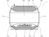
図1および図2に示すように、本発明の一実施形態である空気清浄機1は、各々合成樹脂材で成形された天面パネル11a、右側面パネル11b、左側面パネル11c、底部11dで略直方体状に形成された本体部11を有し、本体部11の一方の面に合成樹脂材で成形された前面パネル12が配置され、他方の面に合成樹脂材で成形されたリアパネル14が配置されている。尚、以降の説明において、必要に応じ本体部11の前面パネル12配置側を本体部前面側、本体部11のリアパネル14配置側を本体部背面側と称する。
前面パネル12の前方には、合成樹脂材で成形されたフロントパネル13が配置され、このフロントパネル13と前面パネル12との間に、本発明の空気吸込口である上面吸込口13a、右側面吸込口13b、および左側面吸込口13cが形成される。また、本体部11とリアパネル14との間に、本発明の空気吹出口である上面吹出口14a、右側面吹出口14b、および左側面吹出口14cが形成される。空気清浄機1では、上面吸込口13a、右側面吸込口13b、および左側面吸込口13cから本体部11に吸い込んだ空気を、上面吹出口14a、右側面吹出口14b、および左側面吹出口14cから室内に吹き出す間に、空気の除塵・加湿および脱臭処理が行われるようになっている。
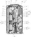
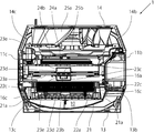
尚、図3および図4に示すように、上面吸込口13a、右側面吸込口13b、および左側面吸込口13cと、上面吹出口14a、右側面吹出口14b、および左側面吹出口14cとを連通する本体部11内部の空間が、本発明の空気清浄機1における通風路10となる。
尚、図3および図4に示すように、上面吸込口13a、右側面吸込口13b、および左側面吸込口13cと、上面吹出口14a、右側面吹出口14b、および左側面吹出口14cとを連通する本体部11内部の空間が、本発明の空気清浄機1における通風路10となる。
空気清浄機1の上面部には、上面吸込口13aの一部を覆うように操作部15が設けられている。操作部15は、電源ボタンや運転モード切り換えボタン等の空気清浄機1を操作するボタンが配置されるとともに、空気清浄機1の運転状態や図示しない塵埃センサ等の検出器における検出結果を表示する表示部が配置されている。
図3に示すように、空気清浄機1の本体部11内部の通風路10には、上面吸込口13a、右側面吸込口13b、および左側面吸込口13cから上面吹出口14a、右側面吹出口14b、および左側面吹出口14cに向かって順に、プレフィルタ21、集塵ユニット22、脱臭ユニット23、加湿ユニット24、送風機25が配置されている。
図3乃至図5に示すように、プレフィルタ21は、例えば糸状のPET材を編みこんで網目構造とした図示しない網目部が合成樹脂材で形成した樹脂枠21aで保持されて構成され、本体部11内部に吸い込まれる空気に含まれる塵埃を捕集する。図4に示すように、プレフィルタ21は、本体部前面側に向かって凸となるようなアーチ形状に形成されているので、プレフィルタ21を平坦な形状とする場合と比べて、上面吸込口13a、右側面吸込口13b、および左側面吸込口13cから本体部11内部に吸い込まれた空気がプレフィルタ21を通過する面積が大きくなるので、より多くの塵埃を捕集することができる。
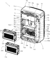
図3および図5に示すように、集塵ユニット22は、第1電気集塵機22aと第2電気集塵機22bとで構成されている。第1電気集塵機22aと第2電気集塵機22bとは上下方向に並べて配置されている。第1電気集塵機22aおよび第2電気集塵機22bは、図示しない放電電極と集塵電極とを有し、後述する仕切板16に設けられた第1電気集塵機22aおよび第2電気集塵機22bに対応する各端子からの給電を受ける。給電を受けた第1電気集塵機22aおよび第2電気集塵機22bは、各々で放電電極によるコロナ放電によりプレフィルタ21で捕集できなかった細かな塵埃や花粉等を帯電させ、帯電した塵埃や花粉等を集塵電極で捕集する。第1電気集塵機22aおよび第2電気集塵機22bは、主に上述した放電電極や集塵電極、および、これらを収納する筐体で形成されているので、空気抵抗が小さい。尚、図5においては、集塵ユニット22(第1電気集塵機22aおよび第2電気集塵機22b)が視認しやすいようにするために、フロントパネル13の描画を省略している。
図6に示すように、第1電気集塵機22aの筐体の左右側面部における高さ方向の略中央部には、第1電気集塵機22aの左右側面から内部に向かって凹状に形成された第1指掛け部22cが設けられている。また、第1電気集塵機22aと同様に、第2電気集塵機22bの筐体の左右側面部における高さ方向の略中央部には、第2電気集塵機22bの左右側面から内部に向かって凹状に形成された第2指掛け部22dが設けられている。これら第1指掛け部22cや第2指掛け部22dは、例えば、金型により簡易に形成できるものであり、人の指が入る程度の大きさに形成されるとともに、各空気吸込口側に指が掛かる壁を形成できる位置に設けられる。尚、第1電気集塵機22aと第2電気集塵機22bとで発揮できる集塵能力を1台の電気集塵機で実現することは可能であるが、そうすれば電気集塵機の重量が、電気集塵機を人の指で保持して空気清浄機1から着脱できる程度の重量(例えば、1kg程度)より重くなって、電気集塵機の取り扱い(本体部11からの着脱作業等)が困難となる虞があるため、本実施形態では第1電気集塵機22aと第2電気集塵機22bの2台の電気集塵機を設けている。
第1電気集塵機22aおよび第2電気集塵機22bの本体部11内部への収納方法や、本体部11からの着脱方法については後述する。
第1電気集塵機22aおよび第2電気集塵機22bの本体部11内部への収納方法や、本体部11からの着脱方法については後述する。
図3および図4に示すように、脱臭ユニット23は、脱臭フィルタ23aと加熱部23
fとを有する。図6に示すように、脱臭フィルタ23aは、例えば、平板材と波形に連続屈曲した屈曲材とを交互に積層してなる波形構造やハニカム構造のような多孔構造の基材を円板形状に形成してなり、その基材23aaに臭気成分を吸着して分解する触媒層23abを設けたものである。図3および図4に示すように、加熱部23fは、PTCヒータ23bと、2枚の放熱板23cと、2個の断熱材23dと、2個のケース23eとで構成される。PTCヒータ23bは、2枚の放熱板23cのうち本体部前面側に配置された放熱板23cに取り付けられて、2枚の放熱板23cを加熱する。2枚の放熱板23cは、各々が略三角形状に形成された金属板であり、図3および図4に示すように、脱臭フィルタ23aの一部を覆うように配置される。2枚の放熱板23cは、脱臭フィルタ23aの中央部に位置する箇所や脱臭フィルタ23aの外径側で接触するように構成されているので、PTCヒータ23bにより本体前面側に配置された放熱板23cだけではなく、本体背面側の放熱板23cも加熱される。断熱材23dは、PTCヒータ23bや放熱板23cを覆うように配置されてPTCヒータ23bや放熱板23cからの熱が外部に逃げることを抑制する。ケース23eは、PTCヒータ23bや放熱板23cや断熱材23dを保持できる形状に形成されている。
このように、脱臭フィルタ23aは多孔構造を有しており、また、加熱部23fが脱臭フィルタ23aの一部のみ覆う構造となっているので、脱臭フィルタ23aの空気抵抗は小さい。
fとを有する。図6に示すように、脱臭フィルタ23aは、例えば、平板材と波形に連続屈曲した屈曲材とを交互に積層してなる波形構造やハニカム構造のような多孔構造の基材を円板形状に形成してなり、その基材23aaに臭気成分を吸着して分解する触媒層23abを設けたものである。図3および図4に示すように、加熱部23fは、PTCヒータ23bと、2枚の放熱板23cと、2個の断熱材23dと、2個のケース23eとで構成される。PTCヒータ23bは、2枚の放熱板23cのうち本体部前面側に配置された放熱板23cに取り付けられて、2枚の放熱板23cを加熱する。2枚の放熱板23cは、各々が略三角形状に形成された金属板であり、図3および図4に示すように、脱臭フィルタ23aの一部を覆うように配置される。2枚の放熱板23cは、脱臭フィルタ23aの中央部に位置する箇所や脱臭フィルタ23aの外径側で接触するように構成されているので、PTCヒータ23bにより本体前面側に配置された放熱板23cだけではなく、本体背面側の放熱板23cも加熱される。断熱材23dは、PTCヒータ23bや放熱板23cを覆うように配置されてPTCヒータ23bや放熱板23cからの熱が外部に逃げることを抑制する。ケース23eは、PTCヒータ23bや放熱板23cや断熱材23dを保持できる形状に形成されている。
このように、脱臭フィルタ23aは多孔構造を有しており、また、加熱部23fが脱臭フィルタ23aの一部のみ覆う構造となっているので、脱臭フィルタ23aの空気抵抗は小さい。
脱臭フィルタ23aの脱臭能力を再生するときは、PTCヒータ23bにより2枚の放熱板23cを加熱し、2枚の放熱板23cにより覆われた脱臭フィルタ23aの一部を加熱する。図示しないモータによって脱臭フィルタ23aを回転させながら脱臭フィルタ23aを加熱することによって、脱臭フィルタ23aに吸着されていた臭気成分の分解が促進され、脱臭フィルタ23aの脱臭能力が再生される。尚、脱臭フィルタ23aが回転するのではなく、放熱板23cが移動することによって脱臭フィルタ23aを加熱してもよい。また、脱臭ユニット23は上記に限らず、加熱手段(PTCヒータ23bおよび放熱板23c)を設けず、触媒層の代わりに活性炭のような臭気成分の吸着材を基材に添加した脱臭フィルタで脱臭ユニットを構成し、吸着能力が低下すれば新しい脱臭フィルタに交換するようにしてもよい。
加湿ユニット24は、加湿フィルタ24aと水を貯留する貯水タンク24bとを有する。加湿フィルタ24aは、円板形状に形成されてその一部が貯水タンク24bに溜められた水に浸った状態で回転軸により回転可能に支持されており、図示しないモータにより回転するようになっている。尚、加湿ユニット24は上記に限らず、回転によって水分を吸い上げる加湿フィルタ24aに代えて、毛細管現象によって水分を吸い上げる加湿フィルタであってもよい。
送風機25は、ターボファン25aとファンモータ25bとを有する。ターボファン25aは、合成樹脂材で形成されており、ファンモータ25bの出力軸に接続されている。ファンモータ25bは回転数可変であり、ファンモータ25bが回転することでターボファン25aも回転し、ターボファン25aの回転によって、空気清浄機1内部へ空気が流入あるいは空気清浄機1内部から空気が流出する。
以上説明した構成を有する空気清浄機1において、使用者が操作部15を操作して空気清浄機1の運転を開始すると、送風機25が駆動するとともに、集塵ユニット22の第1電気集塵機22aおよび第2電気集塵機22bに通電が開始され、加湿ユニット24の加湿フィルタ24aが回転を開始する。送風機25が駆動すると、上面吸込口13a、右側面吸込口13b、および左側面吸込口13cから本体部11内部に空気が吸い込まれる。
本体部11内部に吸い込まれた空気は、1)通風路10における脱臭ユニット23の下
部と加湿ユニット24の上部とが前後方向に重なって配置される箇所では、プレフィルタ21→集塵ユニット22→脱臭ユニット23→加湿ユニット24の順に、2)通風路10における脱臭ユニット23の下部と加湿ユニット24の上部とが前後方向に重なって配置されていない箇所では、プレフィルタ21→集塵ユニット22→脱臭ユニット23の順に、または、プレフィルタ21→集塵ユニット22→加湿ユニット24の順に、それぞれ流れて、上面吹出口14a、右側面吹出口14b、および左側面吹出口14cから空気清浄機1が設置された室内に吹き出される。
部と加湿ユニット24の上部とが前後方向に重なって配置される箇所では、プレフィルタ21→集塵ユニット22→脱臭ユニット23→加湿ユニット24の順に、2)通風路10における脱臭ユニット23の下部と加湿ユニット24の上部とが前後方向に重なって配置されていない箇所では、プレフィルタ21→集塵ユニット22→脱臭ユニット23の順に、または、プレフィルタ21→集塵ユニット22→加湿ユニット24の順に、それぞれ流れて、上面吹出口14a、右側面吹出口14b、および左側面吹出口14cから空気清浄機1が設置された室内に吹き出される。
上記のように空気清浄機1内部の通風路10を空気が通過する際に、プレフィルタ21および通電されている集塵ユニット22で塵埃や花粉が除去される。また、脱臭ユニット23で臭気成分が除去されるとともに、加湿ユニット24で加湿される。尚、上述したように、脱臭ユニット23より各空気吸込口側に集塵ユニット22が配置されているので、脱臭ユニット23に流入する空気は塵埃や花粉等が除去されており、塵埃や花粉等によって脱臭ユニット23の脱臭フィルタ23aが目詰まりすることがない。
次に、図3乃至図7を用いて、第1電気集塵機22aおよび第2電気集塵機22bの本体部11内部への収納方法、および、第1電気集塵機22aおよび第2電気集塵機22bの本体部11からの着脱方法について説明する。
まず、第1電気集塵機22aおよび第2電気集塵機22bの本体部11内部への収納方法について説明する。図3および図4に示すように、本体部11の前面側と前面パネル12との間には、本体部11の一部を構成し通風路10を仕切る仕切板16が配置されている。図6および図7に示すように、仕切板16には、集塵ユニット22を支持する支持部材として、2つの側方支持部材と下方支持部材と上方支持部材とが設けられ、これら各支持部材によって、第1収納部16aや第2収納部16bが形成されている。具体的には、第1収納部16aは、第1側方支持部材16aaと、第1下方支持部材16abと、第1上方支持部材16acと、第1指挿入部16cと、第1上部端子16eと、第1下部端子16fと備えている。第2収納部16bは、第2側方支持部材16baと、第2下方支持部材16bbと、第2上方支持部材16bcと、第2指挿入部16dと、第2上部端子16gと、第2下部端子16hとを備えている。尚、第1指挿入部16cと第2指挿入部16dとが、本発明における切欠部である。
第1収納部16aは第1電気集塵機22aが収納されるスペースであり、図6および図7に示すように、脱臭ユニット23の前面側に配置されている。第1収納部16aは、板状に形成されて水平に仕切板16に配置される第1下方支持部材16abおよび第1上方支持部材16acと、板状に形成されて垂直に仕切板16に配置される2つの第1側方支持部材16aaとで形成されている。第1下方支持部材16abの左右端部と左右の第1側方支持部材16aaの下端部とが接続されており、第1上方支持部材16acの左右端部と左右の第1側方支持部材16aaの上端部とが接続されている。第1側方支持部材16aa、第1下方支持部材16ab、および第1上方支持部材16acで囲まれた空間は、第1電気集塵機22aの形状に対応した形状および寸法とされている。尚、第1収納部16aの背面側は脱臭ユニット23に向けて開口されている。
第2収納部16bは第2電気集塵機22bが収納されるスペースであり、図6および図7に示すように、加湿ユニット24の前面側に配置されている。第2収納部16bは、板状に形成されて水平に仕切板16に配置される第2下方支持部材16bbおよび第2上方支持部材16bcと、板状に形成されて垂直に仕切板16に配置される2つの第2側方支持部材16baとで形成されている。第2下方支持部材16bbの左右端部と左右の第2側方支持部材16baの下端部とが接続されており、第2上方支持部材16bcの左右端部と左右の第2側方支持部材16baの上端部とが接続されている。また、第2側方支持
部材16ba、第2下方支持部材16bb、および第2上方支持部材16bcで囲まれた空間は、第2電気集塵機22bの形状に対応した形状および寸法とされている。尚、第2収納部16bの背面側は加湿ユニット24に向けて開口されている。
部材16ba、第2下方支持部材16bb、および第2上方支持部材16bcで囲まれた空間は、第2電気集塵機22bの形状に対応した形状および寸法とされている。尚、第2収納部16bの背面側は加湿ユニット24に向けて開口されている。
第1指挿入部16cは、左右の第1側方支持部材16aaにおける高さ方向の略中央部を人の指が入る程度の大きさに切り欠いて形成されている。これにより、第1電気集塵機22aを第1収納部16aに収納しているとき、第1電気集塵機22aの左右側面の一部が、第1指挿入部16cの箇所で露出する。また、第2指挿入部16dは、左右の第2側方支持部材16baにおける高さ方向の略中央部を人の指が入る程度の大きさに切り欠いて形成されている。これにより、第2電気集塵機22bを第2収納部16bに収納しているとき、第2電気集塵機22bの左右側面の一部が、第2指挿入部16dの箇所で露出する。
第1上部端子16eおよび第1下部端子16fは、第1電気集塵機22aに給電する一対の電極端子である。第1上部端子16eは、左側の第1側方支持部材16aaにおける第1指挿入部16cの上方に配置されており、第1下部端子16fは、左側の第1側方支持部材16aaにおける左側の第1指挿入部16cの下方に配置されている。第1上部端子16eおよび第1下部端子16fは、第1収納部16aに第1電気集塵機22aが収納されているとき、第1電気集塵機22aに設けられた図示しない受電用端子に各々接触する。
第2上部端子16gおよび第2下部端子16hは、第2電気集塵機22bに給電する一対の電極端子である。第2上部端子16gは、左側の第2側方支持部材16baにおける第2指挿入部16dの上方に配置されており、第2下部端子16hは、左側の第2側方支持部材16baにおける第2指挿入部16dの下方に配置されている。第2上部端子16gおよび第2下部端子16hは、第2収納部16bに第2電気集塵機22bが収納されているとき、第2電気集塵機22bに設けられた図示しない受電用端子に各々接触する。
また、第1収納部16aおよび第2収納部16bには、上側止め部16jと、中央止め部16kと、下側止め部16mとが設けられている。上側止め部16jは、第1収納部16aの第1上方支持部材16acにおける左右方向の中央部に配置されている。中央止め部16kは、第2収納部16bの第2上方支持部材16bcにおける左右方向の中央部に配置されている。下側止め部16mは、第2収納部16bの第2下方支持部材16bbにおける左右方向の中央部に配置されている。図7に示すように、上側止め部16j、中央止め部16k、下側止め部16mは、いずれも略直方体形状に形成されている。
次に、第1電気集塵機22aおよび第2電気集塵機22bを、夫々空気清浄機1から取り外す場合の手順について、図5乃至図7を用いて説明する。図5に示すように、第1電気集塵機22aが第1収納部16aに、第2電気集塵機22bが第2収納部16dに、各々収納されているとき、上側止め部16j、中央止め部16k、下側止め部16mは、各々の端部が第1電気集塵機22aの前面部や第2電気集塵機22bの前面部に係合する位置に回動されている。具体的には、上側止め部16jは、いずれか一端が第1電気集塵機22aの前面部上側に係合するよう回動され、中央止め部16kは、一端が第1電気集塵機22aの前面部下側に、他端が第2電気集塵機22bの前面部上側に各々係合するように回動され、下側止め部16mは、いずれか一端が第1電気集塵機22aの前面部下側に係合するように回動される。これにより、第1電気集塵機22aが第1収納部16aから前方方向に抜け出すことや、第2電気集塵機22bが第2収納部16bから前方方向に抜け出すことを防いでいる。
また、図4に示すように、第1電気集塵機22aが第1収納部16aに収納されている
とき、第1電気集塵機22aに設けられた第1指掛け部22cが第1指挿入部16cから露出した状態となっている。また、第2電気集塵機22bの第2指掛け部22dが第2指挿入部16dから露出した状態となっている。
とき、第1電気集塵機22aに設けられた第1指掛け部22cが第1指挿入部16cから露出した状態となっている。また、第2電気集塵機22bの第2指掛け部22dが第2指挿入部16dから露出した状態となっている。
第1電気集塵機22aおよび第2電気集塵機22bを取り外すときは、まず、空気清浄機1からフロントパネル13とプレフィルタ21とを取り外し、次に、上側止め部16j、中央止め部16k、下側止め部16mを、各々の端部が第1電気集塵機22aの前面部や第2電気集塵機22bの前面部に係合しない位置に回動される。具体的には、まず、上側止め部16jと中央止め部16kとを、各々の端部が第1電気集塵機22aの前面部に係合しない位置まで回動させ、左右の第1指挿入部16cから露出している第1電気集塵機22aの第1指掛け部22cに指を掛けて前方へ引き抜いて、第1電気集塵機22aを第1収納部16aから取り外す。続いて、下側止め部16mを端部が第2電気集塵機22bの前面部に係合しない位置まで回動させ(中央止め部16kは、上記第1電気集塵機22aの取り外しの際に回動済)、左右の第2指挿入部16dから露出している第2電気集塵機22bの第2収納部22dに指を掛けて前方へ引き抜いて、第2電気集塵機22bを第2収納部16bから取り外す。
次に、第1電気集塵機22aおよび第2電気集塵機22bを、夫々空気清浄機1に取り付ける場合の手順について説明する。まず、上側止め部16j、中央止め部16k、下側止め部16mを、各々の端部が第1電気集塵機22aの前面部や第2電気集塵機22bの前面部に係合しない位置、つまり、第1電気集塵機22aや第2電気集塵機22bを第1収納部16aや第2収納部16bに取り付ける際に邪魔にならない位置まで各々を回動させる。
次に、第1電気集塵機22aの第1指掛け部22cを指で保持し、第1電気集塵機22aを第1収納部16aに挿入する。このとき、左右の第1指挿入部16cがあるため、第1電気集塵機22aを保持している指が挿入作業の妨げとならない。
次に、第2電気集塵機22bの第2指掛け部22dを指で保持し、第2電気集塵機22bを第2収納部16bに挿入する。このとき、左右の第2指挿入部16dがあるため、第2電気集塵機22bを保持している指が挿入作業の妨げとならない。
第1電気集塵機22aおよび第2電気集塵機22bを各々挿入した後、上側止め部16j、中央止め部16k、下側止め部16mを、各々の端部が第1電気集塵機22aの前面部や第2電気集塵機22bの前面部に係合する位置に回動させて、図5に示すような状態とし、第1電気集塵機22aの第1収納部16aから前方方向への抜け出し、および、第2電気集塵機22bの第2収納部16bから前方方向への抜け出しを防止する。そして、プレフィルタ21とフロントパネル13とを空気清浄機1に装着する。
以上説明したように、第1指挿入部16cや第2指挿入部16dに露出している第1電気集塵機22aの第1指掛け部22cおよび第2電気集塵機22bの第2指掛け部22dに指を掛けて、第1収納部16aや第2収納部16bから第1電気集塵機22aや第2電気集塵機22bを取り外す、あるいは、第1収納部16aや第2収納部16bに第1電気集塵機22aや第2電気集塵機22bを収納できるので、第1電気集塵機22aや第2電気集塵機22bの着脱作業が簡単に行える。また、第1電気集塵機22aおよび第2電気集塵機22bの重量を、第1電気集塵機22aや第2電気集塵機22bを人の指で保持して第1収納部16aや第2収納部16bに着脱できる程度の重量としているので、第1電気集塵機22aや第2電気集塵機22bを着脱する際の、第1電気集塵機22aや第2電気集塵機22bの持ち運びが簡易となる。
また、集塵ユニット25の集塵能力が本実施形態の空気清浄機1より低くてよい場合は、電気集塵機を1台とすればよく、また、本実施形態より高い集塵能力が必要な場合は、電気集塵機を3台以上設ければよい。このように、必要な集塵能力に応じて、人の指で保持して収納部に着脱できる程度の重量とした電気集塵機の台数を増減できることで、電気集塵機の着脱作業を簡易としつつ、必要とされる集塵能力にも柔軟に対応できる。
また、第1指挿入部16cや第2指挿入部16dが、第1側方支持部材16aaや第2側方支持部材16baに設けられているが、これらのうち左側の第1指挿入部16cや第2指挿入部16dは、第1側方支持部材16aaや第2側方支持部材16baにおける第1上部端子16e、第1下部端子16f、第2上部端子16g、および第2下部端子16hが設けられている箇所以外の空スペースを利用して設けられている。このため、第1指挿入部16cや第2指挿入部16dを設けるために、空気清浄機1の筐体が大型化することがない。
尚、第1電気集塵機22aや第2電気集塵機22bが、第1収納部16aや第2収納部16bに収納されているとき、第1電気集塵機22aと第1指挿入部16cとの間や、第2電気集塵機22bと第2指挿入部16dとの間には隙間が生じる虞があり、この隙間を通して第1電気集塵機22aや第2電気集塵機22bを通過せずに脱臭ユニット23や加湿ユニット24に塵埃や花粉等が除去されていない空気が流れる虞がある。これに対して、図4および図5に示すように、第1指挿入部16cや第2指挿入部16dの前方を樹脂枠21aの一部(樹脂枠21aの左右側片部)で覆うようにプレフィルタ21を配置して、上述した隙間へ流れる空気量が最小量となるようにしている。
以上説明した通り、本発明の空気清浄機は、集塵ユニットの支持部材に切欠部が設けられているので、使用者は切欠部に露出している集塵ユニットの側面部を指で保持して集塵ユニットの着脱が行える。このため、集塵ユニットに把手を設けることなく、つまり、集塵ユニットの構造を簡単にしつつ集塵ユニットを簡易に着脱できる。また、集塵ユニットに把手を設けた場合に必要となる逃げ部も必要なく、空気清浄機の大型化を抑制できる。
尚、以上説明した実施形態では、集塵ユニットを構成する電気集塵機が2台である場合について説明したが、電気集塵機は1台でもよく、また、3台以上であってもよい。また、仕切板16に設けられる収納部は、電気集塵機の台数に応じて増減すればよい。また、電気集塵機2台を上下に並べて配置する場合について説明したが、電気集塵機を左右に並べて配置してもよい。電気集塵機を左右に並べて配置する場合は、収納部は左右に並べて仕切板16に設けられることになり、このとき、指挿入部は収納部の上下側端部における左右方向の略中央部に設ければよい。
1 空気清浄機
10 通風路
11 本体部
12 前面パネル
13 フロントパネル
13a 上面吸込口
13b 右側面吸込口
13c 左側面吸込口
14 リアパネル
14a 上面吹出口
14b 右側面吹出口
14c 左側面吹出口
16 仕切板
16a 第1収納部
16aa 第1側方支持部材
16ab 第1下方支持部材
16ac 第1上方支持部材
16b 第2収納部
16ba 第2側方支持部材
16bb 第2下方支持部材
16bc 第2上方支持部材
16c 第1指挿入部
16d 第2指挿入部
16e 第1上部端子
16f 第1下部端子
16g 第2上部端子
16h 第2下部端子
16j 上側止め部
16k 中央止め部
16g 下側止め部
21 プレフィルタ
22 集塵ユニット
22a 第1電気集塵機
22b 第2電気集塵機
23 脱臭ユニット
23a 脱臭フィルタ
23b PTCヒータ
23c 放熱板
23f 加熱部
24 加湿ユニット
24a 加湿フィルタ
24b 貯水タンク
25 送風機
25a ターボファン
25b ファンモータ
10 通風路
11 本体部
12 前面パネル
13 フロントパネル
13a 上面吸込口
13b 右側面吸込口
13c 左側面吸込口
14 リアパネル
14a 上面吹出口
14b 右側面吹出口
14c 左側面吹出口
16 仕切板
16a 第1収納部
16aa 第1側方支持部材
16ab 第1下方支持部材
16ac 第1上方支持部材
16b 第2収納部
16ba 第2側方支持部材
16bb 第2下方支持部材
16bc 第2上方支持部材
16c 第1指挿入部
16d 第2指挿入部
16e 第1上部端子
16f 第1下部端子
16g 第2上部端子
16h 第2下部端子
16j 上側止め部
16k 中央止め部
16g 下側止め部
21 プレフィルタ
22 集塵ユニット
22a 第1電気集塵機
22b 第2電気集塵機
23 脱臭ユニット
23a 脱臭フィルタ
23b PTCヒータ
23c 放熱板
23f 加熱部
24 加湿ユニット
24a 加湿フィルタ
24b 貯水タンク
25 送風機
25a ターボファン
25b ファンモータ
Claims (5)
- 筐体内に空気を吸い込む空気吸込口と、筐体内から外部へ空気を吹き出す空気吹出口と、前記空気吸込口と前記空気吹出口とを連通させる通風路を備える本体部とを有し、
前記本体部内に、取り込んだ空気を除塵する集塵ユニットと送風機とを備えた空気清浄機であって、
前記本体部には、前記集塵ユニットを前記本体部内における前記空気吸込口側に配置するための支持部材が備えられ、
前記支持部材に切欠部が設けられている、
ことを特徴とする空気清浄機。 - 前記集塵ユニットの側面には、前記切欠部の位置に対応して配置され前記集塵ユニット内部に向けて凹状に形成された指掛け部を備える、
ことを特徴とする請求項1に記載の空気清浄機。 - 前記集塵ユニットは直方体形状に形成され、
前記支持部材は、前記集塵ユニットの上下側面あるいは左右側面のうち少なくともいずれか一方を指示する、
ことを特徴とする請求項1または請求項2に記載の空気清浄機。 - 前記集塵ユニットの前方に、前記空気吸込口から取り込まれた空気に含まれる塵埃を除去するためのプレフィルタが配置され、
前記プレフィルタは、塵埃を捕獲する網目部と、同網目部を保持する樹脂枠とで構成され、
前記切欠部における前記空気吸込口側を前記樹脂枠で覆うように、前記プレフィルタが配置されている、
ことを特徴とする請求項1乃至請求項3に記載の空気清浄機。 - 前記集塵ユニットが電気集塵機で構成され、
前記支持部材に、前記電気集塵機に給電する端子が設けられている、
ことを特徴とする請求項1乃至請求項4に記載の空気清浄機。
Applications Claiming Priority (2)
| Application Number | Priority Date | Filing Date | Title |
|---|---|---|---|
| JP2014117499A JP6020842B2 (ja) | 2014-06-06 | 2014-06-06 | 空気清浄機 |
| JP2014-117499 | 2014-06-06 |
Publications (1)
| Publication Number | Publication Date |
|---|---|
| WO2015186802A1 true WO2015186802A1 (ja) | 2015-12-10 |
Family
ID=54766870
Family Applications (1)
| Application Number | Title | Priority Date | Filing Date |
|---|---|---|---|
| PCT/JP2015/066248 Ceased WO2015186802A1 (ja) | 2014-06-06 | 2015-06-04 | 空気清浄機 |
Country Status (4)
| Country | Link |
|---|---|
| JP (1) | JP6020842B2 (ja) |
| CN (1) | CN105276695A (ja) |
| TW (1) | TW201604496A (ja) |
| WO (1) | WO2015186802A1 (ja) |
Citations (3)
| Publication number | Priority date | Publication date | Assignee | Title |
|---|---|---|---|---|
| JPH1099718A (ja) * | 1996-09-30 | 1998-04-21 | Daikin Ind Ltd | 空気清浄機 |
| JPH10311571A (ja) * | 1997-05-09 | 1998-11-24 | Matsushita Seiko Co Ltd | 空気清浄機 |
| JP2005098657A (ja) * | 2003-09-26 | 2005-04-14 | Zexel Valeo Climate Control Corp | 空調装置及びそのフィルタユニット |
Family Cites Families (5)
| Publication number | Priority date | Publication date | Assignee | Title |
|---|---|---|---|---|
| JP2000005540A (ja) * | 1998-06-19 | 2000-01-11 | Zojirushi Corp | 空気清浄機のフィルタ取付構造 |
| JP2002045632A (ja) * | 2000-08-04 | 2002-02-12 | Matsushita Seiko Co Ltd | 空気清浄機 |
| CN1541750A (zh) * | 2003-04-30 | 2004-11-03 | 乐金电子(天津)电器有限公司 | 空气净化器的集尘过滤器的安装结构 |
| CN100360864C (zh) * | 2003-04-30 | 2008-01-09 | 乐金电子(天津)电器有限公司 | 空气净化器的集尘过滤器 |
| JP5128310B2 (ja) * | 2008-02-28 | 2013-01-23 | シロキ工業株式会社 | 中間ロック機構を備えた車両用スライドデッキ装置 |
-
2014
- 2014-06-06 JP JP2014117499A patent/JP6020842B2/ja not_active Expired - Fee Related
-
2015
- 2015-03-23 CN CN201510126580.3A patent/CN105276695A/zh active Pending
- 2015-06-04 WO PCT/JP2015/066248 patent/WO2015186802A1/ja not_active Ceased
- 2015-06-08 TW TW104118539A patent/TW201604496A/zh unknown
Patent Citations (3)
| Publication number | Priority date | Publication date | Assignee | Title |
|---|---|---|---|---|
| JPH1099718A (ja) * | 1996-09-30 | 1998-04-21 | Daikin Ind Ltd | 空気清浄機 |
| JPH10311571A (ja) * | 1997-05-09 | 1998-11-24 | Matsushita Seiko Co Ltd | 空気清浄機 |
| JP2005098657A (ja) * | 2003-09-26 | 2005-04-14 | Zexel Valeo Climate Control Corp | 空調装置及びそのフィルタユニット |
Also Published As
| Publication number | Publication date |
|---|---|
| TW201604496A (zh) | 2016-02-01 |
| JP2015229153A (ja) | 2015-12-21 |
| CN105276695A (zh) | 2016-01-27 |
| JP6020842B2 (ja) | 2016-11-02 |
Similar Documents
| Publication | Publication Date | Title |
|---|---|---|
| JP5999149B2 (ja) | 空気清浄機 | |
| CN203036792U (zh) | 加湿装置 | |
| CN205783443U (zh) | 空气净化机 | |
| CN108686510A (zh) | 吸附单元及空气净化器 | |
| JP6646032B2 (ja) | 空気清浄装置 | |
| JP5900562B1 (ja) | 空気清浄機 | |
| JP2982707B2 (ja) | 空気清浄機 | |
| JP5958507B2 (ja) | 空気清浄機 | |
| CN105363284B (zh) | 空气净化机 | |
| JP6020842B2 (ja) | 空気清浄機 | |
| JP6281593B2 (ja) | 空気清浄機 | |
| JP6405802B2 (ja) | 空気清浄機 | |
| JP6405803B2 (ja) | 空気清浄機 | |
| JP5900678B1 (ja) | 空気清浄機 | |
| JP6020843B2 (ja) | 空気清浄機 | |
| JP6405798B2 (ja) | 空気清浄機 | |
| JP2006017425A (ja) | 空気調和機 | |
| WO2015186804A1 (ja) | 空気清浄機 | |
| JP5630787B2 (ja) | 空気循環パネル | |
| JP2015230146A (ja) | 空気清浄機 | |
| JP2011252653A (ja) | 空気清浄装置および加湿機能付き空気清浄装置 | |
| JP2015230145A (ja) | 空気清浄機 | |
| JP2016056985A (ja) | 空気調和機 | |
| JP2017110859A (ja) | 空気調和機 | |
| JP2012052776A (ja) | 空気調和機の室内機 |
Legal Events
| Date | Code | Title | Description |
|---|---|---|---|
| 121 | Ep: the epo has been informed by wipo that ep was designated in this application |
Ref document number: 15803182 Country of ref document: EP Kind code of ref document: A1 |
|
| NENP | Non-entry into the national phase |
Ref country code: DE |
|
| 122 | Ep: pct application non-entry in european phase |
Ref document number: 15803182 Country of ref document: EP Kind code of ref document: A1 |