WO2015186776A1 - ガスセンサ素子 - Google Patents
ガスセンサ素子 Download PDFInfo
- Publication number
- WO2015186776A1 WO2015186776A1 PCT/JP2015/066161 JP2015066161W WO2015186776A1 WO 2015186776 A1 WO2015186776 A1 WO 2015186776A1 JP 2015066161 W JP2015066161 W JP 2015066161W WO 2015186776 A1 WO2015186776 A1 WO 2015186776A1
- Authority
- WO
- WIPO (PCT)
- Prior art keywords
- gas
- measured
- cell
- electrode
- concentration
- Prior art date
- Legal status (The legal status is an assumption and is not a legal conclusion. Google has not performed a legal analysis and makes no representation as to the accuracy of the status listed.)
- Ceased
Links
Images


Classifications
-
- G—PHYSICS
- G01—MEASURING; TESTING
- G01N—INVESTIGATING OR ANALYSING MATERIALS BY DETERMINING THEIR CHEMICAL OR PHYSICAL PROPERTIES
- G01N27/00—Investigating or analysing materials by the use of electric, electrochemical, or magnetic means
- G01N27/26—Investigating or analysing materials by the use of electric, electrochemical, or magnetic means by investigating electrochemical variables; by using electrolysis or electrophoresis
- G01N27/403—Cells and electrode assemblies
- G01N27/406—Cells and probes with solid electrolytes
- G01N27/407—Cells and probes with solid electrolytes for investigating or analysing gases
- G01N27/41—Oxygen pumping cells
-
- G—PHYSICS
- G01—MEASURING; TESTING
- G01N—INVESTIGATING OR ANALYSING MATERIALS BY DETERMINING THEIR CHEMICAL OR PHYSICAL PROPERTIES
- G01N27/00—Investigating or analysing materials by the use of electric, electrochemical, or magnetic means
- G01N27/26—Investigating or analysing materials by the use of electric, electrochemical, or magnetic means by investigating electrochemical variables; by using electrolysis or electrophoresis
- G01N27/416—Systems
- G01N27/417—Systems using cells, i.e. more than one cell and probes with solid electrolytes
- G01N27/419—Measuring voltages or currents with a combination of oxygen pumping cells and oxygen concentration cells
-
- G—PHYSICS
- G01—MEASURING; TESTING
- G01M—TESTING STATIC OR DYNAMIC BALANCE OF MACHINES OR STRUCTURES; TESTING OF STRUCTURES OR APPARATUS, NOT OTHERWISE PROVIDED FOR
- G01M15/00—Testing of engines
- G01M15/04—Testing internal-combustion engines
- G01M15/10—Testing internal-combustion engines by monitoring exhaust gases or combustion flame
- G01M15/102—Testing internal-combustion engines by monitoring exhaust gases or combustion flame by monitoring exhaust gases
- G01M15/104—Testing internal-combustion engines by monitoring exhaust gases or combustion flame by monitoring exhaust gases using oxygen or lambda-sensors
-
- G—PHYSICS
- G01—MEASURING; TESTING
- G01N—INVESTIGATING OR ANALYSING MATERIALS BY DETERMINING THEIR CHEMICAL OR PHYSICAL PROPERTIES
- G01N27/00—Investigating or analysing materials by the use of electric, electrochemical, or magnetic means
- G01N27/26—Investigating or analysing materials by the use of electric, electrochemical, or magnetic means by investigating electrochemical variables; by using electrolysis or electrophoresis
- G01N27/403—Cells and electrode assemblies
- G01N27/406—Cells and probes with solid electrolytes
- G01N27/407—Cells and probes with solid electrolytes for investigating or analysing gases
- G01N27/4071—Cells and probes with solid electrolytes for investigating or analysing gases using sensor elements of laminated structure
- G01N27/4072—Cells and probes with solid electrolytes for investigating or analysing gases using sensor elements of laminated structure characterized by the diffusion barrier
-
- G—PHYSICS
- G01—MEASURING; TESTING
- G01N—INVESTIGATING OR ANALYSING MATERIALS BY DETERMINING THEIR CHEMICAL OR PHYSICAL PROPERTIES
- G01N27/00—Investigating or analysing materials by the use of electric, electrochemical, or magnetic means
- G01N27/26—Investigating or analysing materials by the use of electric, electrochemical, or magnetic means by investigating electrochemical variables; by using electrolysis or electrophoresis
- G01N27/416—Systems
Definitions
- the present disclosure relates to a gas sensor element that detects a concentration of a predetermined gas component contained in exhaust gas flowing through an exhaust pipe of an internal combustion engine.
- a gas sensor element that detects the concentration of a predetermined gas component such as nitrogen oxide (NOx) is used in an exhaust pipe of an internal combustion engine.
- a voltage is applied to a pair of electrodes provided on both the front and back surfaces of the solid electrolyte body to adjust the oxygen concentration in the exhaust gas as the gas to be measured to a predetermined concentration or less.
- the concentration of oxygen remaining after adjusting the oxygen concentration is measured, or the oxygen concentration is further adjusted after adjusting the oxygen concentration. ing.
- the oxygen concentration in the gas to be measured is adjusted by an oxygen pump cell formed by providing a pair of electrodes on the solid electrolyte body.
- the concentration of oxygen remaining in the gas to be measured is detected by an oxygen monitor cell formed with electrodes.
- the concentration of a predetermined gas component in the gas to be measured is detected by a sensor cell formed by providing a pair of electrodes on the solid electrolyte body. Then, by subtracting the oxygen ion current value detected as the residual oxygen concentration from the oxygen ion current value detected as indicating the concentration of the predetermined gas component, the influence of the residual oxygen on the detection of the concentration of the predetermined gas component is obtained. Reduced.
- the electrode material constituting the oxygen monitor cell is different from the electrode material constituting the sensor cell. Therefore, there is a difference between the oxygen monitor cell and the sensor cell with respect to the output sensitivity to the oxygen concentration, the degree of sensitivity reduction due to deterioration, and the like. This difference becomes an error factor when the concentration of the predetermined gas component is detected by the gas sensor element. Therefore, by subtracting the oxygen ion current value in the oxygen monitor cell from the oxygen ion current value in the sensor cell, the detection accuracy of the concentration of the predetermined gas component cannot be further improved.
- the present invention has been made in view of the above problems, and provides a gas sensor element that can effectively improve the detection accuracy of the concentration of a predetermined gas component with a simple structure.
- a gas sensor element that is disposed in an exhaust pipe of an internal combustion engine and detects a concentration of a predetermined gas component in exhaust gas flowing through the exhaust pipe, A solid electrolyte body having oxygen ion conductivity; A gas space to be measured formed on one surface side of the solid electrolyte body and into which the exhaust gas as the gas to be measured is introduced through the diffusion resistor; A reference gas space formed on the other surface side of the solid electrolyte body and into which a reference gas is introduced; A pump electrode provided on the surface of the solid electrolyte body on the measured gas space side, and a voltage between the pump electrode and a reference electrode provided on the surface of the solid electrolyte body on the reference gas space side; A pump cell for adjusting the oxygen concentration in the measured gas space, It has a sensor electrode provided on the surface of the solid electrolyte body on the measurement gas space side, which is provided at a position downstream of the arrangement position of the pump electrode in the flow direction of the measurement gas.
- a sensor cell for measuring an oxygen ion current flowing between the sensor electrode and the reference electrode, From the oxygen ion current value measured by the sensor cell when fuel is injected in the internal combustion engine, the oxygen ion current measured by the sensor cell after elapse of a predetermined time from when the fuel injection is cut off in the internal combustion engine.
- a gas sensor element configured to subtract a value to detect the concentration of the predetermined gas component is provided.
- the gas sensor element uses a sensor cell to reduce the influence of the concentration of oxygen remaining in the gas to be measured after adjusting the oxygen concentration by the pump cell on the detection accuracy of the concentration of the predetermined gas component.
- the gas sensor element is measured by the sensor cell after a lapse of a predetermined time from the time when the fuel injection is cut off in the internal combustion engine from the oxygen ion current value measured by the sensor cell when the fuel injection is performed in the internal combustion engine.
- the concentration of the predetermined gas component is detected by subtracting the oxygen ion current value.
- the oxygen ion current value when the concentration of the predetermined gas component is not detected by the sensor cell is subtracted from the oxygen ion current value when the concentration of the predetermined gas component is detected by the sensor cell. Therefore, the influence of the residual oxygen concentration in the gas to be measured on the detection accuracy of the concentration of the predetermined gas component is reduced.
- the gas sensor element effectively improves the detection accuracy of the concentration of the predetermined gas component with a simple structure.
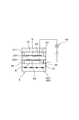
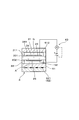
- FIG. 1 is a cross-sectional view showing a gas sensor element according to Example 1.
- FIG. FIG. 2 is a cross-sectional view taken along the line II of FIG. 1 according to the first embodiment.
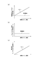
- (A) is a graph which shows the relationship between NOx density
- FIG. (B) is a graph which shows the relationship between the NOx density
- FIG. (C) is a graph showing the relationship between the NOx concentration and the corrected sensor cell output current value according to Example 1.
- FIG. FIG. 6 is a cross-sectional view taken along the line III-III in FIG.
- the predetermined time is determined based on a time difference until the exhaust gas reaches the gas sensor element in the exhaust pipe from the internal combustion engine in consideration of the flow rate of the exhaust gas in the internal combustion engine.
- the gas space to be measured includes a first gas space in which the pump cell is disposed and a second gas space in which the sensor cell is disposed, and the first gas space, the second gas space, May be communicated in a state of being partitioned by an obstacle wall that reduces the space cross-sectional area in the flow direction of the gas to be measured, or a porous body having a gas-permeating property.
- the gas to be measured can be retained as long as possible in the first gas space where the pump electrode of the pump cell is arranged. And the precision which adjusts the oxygen concentration in to-be-measured gas by a pump cell can be improved. As a result, further improvement in detection accuracy of the concentration of the predetermined gas component in the gas sensor element can be expected.
- the second gas space is provided with an auxiliary pump cell that further adjusts the oxygen concentration in the gas to be measured after the oxygen concentration is adjusted by the pump cell, and the auxiliary pump cell includes the solid electrolyte body. And an auxiliary pump electrode provided on the surface of the measured gas space, and a voltage is applied between the auxiliary pump electrode and the reference electrode to adjust the oxygen concentration in the second gas space. It may be configured.
- the accuracy of adjusting the oxygen concentration in the gas to be measured can be further improved by the auxiliary pump cell.
- further improvement in detection accuracy of the concentration of the predetermined gas component in the gas sensor element can be expected.
- Example 1 The gas sensor element 1 is disposed in an exhaust pipe of an internal combustion engine and is used for detecting the concentration of a predetermined gas component in exhaust gas flowing through the exhaust pipe.
- the gas sensor element 1 includes a solid electrolyte body 2 having oxygen ion conductivity, a measured gas space 51, a reference gas space 52, a pump cell 41, and a sensor cell 42.
- the measured gas space 51 is formed on one surface side of the solid electrolyte body 2, and is a space into which exhaust gas as the measured gas G is introduced through the diffusion resistor 32.
- the reference gas space 52 is formed on the other surface side of the solid electrolyte body 2 and is a space into which the reference gas A is introduced.
- the pump cell 41 has a pump electrode 21 provided on the surface 201 of the solid electrolyte body 2 on the measured gas space 51 side.
- the pump cell 41 applies a voltage between the pump electrode 21 and the reference electrode 25 provided on the surface 202 of the solid electrolyte body 2 on the reference gas space 52 side so as to adjust the oxygen concentration in the gas space 51 to be measured. It is configured.
- the sensor cell 42 has the sensor electrode 22 provided on the surface 201 of the solid electrolyte body 2 on the measured gas space 51 side.
- the sensor electrode 22 is provided at a position downstream of the arrangement position of the pump electrode 21 in the flow direction F of the gas G to be measured.
- the sensor cell 42 is configured to measure an oxygen ion current that flows between the sensor electrode 22 and the reference electrode 25.
- the gas sensor element 1 performs fuel injection in the internal combustion engine from the oxygen ion current value I1 measured by the sensor cell 42 when fuel injection is performed in the internal combustion engine. It is configured to detect the concentration of the predetermined gas component based on the corrected oxygen ion current value I obtained by subtracting the oxygen ion current value I2 measured by the sensor cell 42 after a predetermined time has elapsed since the disconnection.
- the gas sensor element 1 will be described in detail below with reference to FIGS.
- the gas sensor element 1 is disposed and used in an exhaust pipe of an automobile while being disposed in a cover.
- the gas G to be measured is exhaust gas that passes through the exhaust pipe, and the gas sensor element 1 is used to detect the concentration of NOx (nitrogen oxide) as a predetermined gas component contained in the exhaust gas.
- NOx nitrogen oxide
- the gas sensor element 1 can also be made to measure the concentration of NH 3 (ammonia).
- the pump electrode 21, the sensor electrode 22, and the reference electrode 25 are provided on one solid electrolyte body 2.
- an insulator 31 for forming the measurement gas space 51 is laminated via an insulating first spacer 311.
- a heater 6 for heating the solid electrolyte body 2 via an insulating second spacer 33 is laminated.
- the gas sensor element 1 has a long shape, and is configured to introduce the gas G to be measured from one side in the longitudinal direction L.
- the diffusion resistor 32 is embedded in the introduction port 312 of the measurement gas G formed at one end portion in the longitudinal direction L of the first spacer 311.
- the flow direction F of the gas G to be measured in the gas sensor element 1 is a direction from one side of the longitudinal direction L toward the other side.
- the diffusion resistor 32 is formed of a porous body having a gas-permeating property, and the measurement gas G is introduced into the measurement gas space 51 at a predetermined diffusion rate.
- the heater 6 is configured by providing a conductor layer 62 for energization between insulator substrates 61.
- the conductor layer 62 has a heating conductor portion 621 disposed at a position facing the pump electrode 21 and the sensor electrode 22, and a pair of lead portions 622 connected to both ends of the heating conductor portion 621.
- the pump cell 41 has voltage applying means for applying a voltage between the pump electrode 21 and the reference electrode 25.
- the sensor cell 42 has current measuring means for measuring the current flowing between the sensor electrode 22 and the reference electrode 25.
- the solid electrolyte body 2 is a zirconia substrate having oxygen ion conductivity.
- the reference electrode 25 of this example is provided in common to these electrodes 21 and 22 at a position facing the pump electrode 21 and the sensor electrode 22.
- the reference electrode 25 can be provided separately for each of the pump electrode 21 and the sensor electrode 22.
- the pump electrode 21 and the reference electrode 25 are configured using platinum and gold as materials having oxygen decomposition performance
- the sensor electrode 22 is configured using platinum and rhodium as materials having NOx decomposition performance. Has been.
- the operation of detecting the NOx concentration as the concentration of the predetermined gas component in the gas sensor element 1 and the operation and effect of the gas sensor element 1 will be described.
- the gas sensor element 1 detects the NOx concentration in the measured gas G
- the exhaust gas as the measured gas G passes through the diffusion resistor 32 and is introduced into the measured gas space 51. Further, the atmosphere as the reference gas A is introduced into the reference gas space 52.
- the gas G to be measured whose oxygen concentration has been adjusted by the pump cell 41 flows to the downstream side (the other side) of the gas space 51 to be measured.
- an oxygen ion current value I1 of an amount corresponding to the NOx concentration and the residual oxygen concentration flows between the sensor electrode 22 and the reference electrode 25.
- the gas sensor element 1 reduces the influence of the residual oxygen concentration in the gas space 51 to be measured on the detection accuracy of the NOx concentration by utilizing a state in which NOx is hardly exhausted from the internal combustion engine. That is, in a state where NOx is hardly exhausted from the internal combustion engine (fuel cut state), as shown in FIG. 3B, an amount of oxygen corresponding to the oxygen concentration is provided between the sensor electrode 22 and the reference electrode 25. An ion current value I2 flows. In the pump cell 41, the oxygen concentration in the measurement gas G is always controlled to be constant. Therefore, it is considered that the oxygen ion current value I2 in the sensor cell 42 at the time of fuel cut is substantially the same as the oxygen ion current value I2 'in the sensor cell 42 at the time of combustion in the internal combustion engine.
- the oxygen ion current value I2 in the sensor cell 42 at the time of fuel cut is the oxygen ion current value I2 measured by the sensor cell 42 after a predetermined time has elapsed since the fuel injection was cut off in the internal combustion engine.
- the oxygen ion current value I1 in the sensor cell 42 at the normal time is an oxygen ion current value I1 measured according to the NOx concentration and the residual oxygen concentration when fuel is injected in the internal combustion engine.
- the fuel injection in the internal combustion engine is cut off from the oxygen ion current value I1 in the sensor cell 42 at the normal time when the fuel injection is performed in the internal combustion engine.
- the corrected oxygen ion current value I is obtained by subtracting the oxygen ion current value I2 measured by the sensor cell 42 after a predetermined time has elapsed. Then, the concentration of the predetermined gas component is detected based on the corrected oxygen ion current value I.
- the oxygen ion current value when the NOx concentration is not detected by the sensor cell 42 is subtracted from the oxygen ion current value when the NOx concentration is detected by the sensor cell 42. Therefore, the influence of the residual oxygen concentration in the measurement gas G on the detection accuracy of the NOx concentration is reduced.
- the gas sensor element 1 of this example effectively improves the detection accuracy of the NOx concentration with a simple structure.
- the gas space 51 to be measured includes a first gas space 511 in which the pump cell 41 is disposed, and a second gas space 512 in which the sensor cell 42 is disposed. And is composed of.
- the first gas space 511 is formed on one side in the longitudinal direction L where the diffusion resistor 32 is provided, and the second gas space 512 is adjacent to the first gas space 511 and on the other side in the longitudinal direction L. Is formed. Then, the gas to be measured G is retained in the first gas space 511 for as long as possible to make it difficult for residual oxygen in the gas to be measured G to flow to the sensor electrode 22 in the second gas space 512.
- the first gas space 511 and the second gas space 512 are in communication with each other in a state of being partitioned by an obstacle wall 34 that reduces the space cross-sectional area in the flow direction F of the gas G to be measured.
- the obstacle wall 34 is provided so as to protrude from the surface 201 of the solid electrolyte body 2 on the measured gas space 51 side, and a slit through which the measured gas G passes between the insulator 31 and the end face of the obstacle wall 34.
- a (gap) 341 is formed.
- first gas space 511 and the second gas space 512 can be partitioned by a porous body having a property of allowing gas to pass through instead of being partitioned by the obstacle wall 34.
- the porous body can be provided in a state in which the first gas space 511 and the second gas space 512 are completely partitioned.
- Other structures of the gas sensor element 1 of this example and the reference numerals in the figure are the same as those of the first embodiment, and the same effects as those of the first embodiment can be obtained by the gas sensor element 1 of this example.
- Example 3 In the gas sensor element 1 of this example, as shown in FIGS. 6 and 7, the oxygen concentration in the measurement gas G after the oxygen concentration is adjusted by the pump cell 41 is further adjusted in the second gas space 512.
- An auxiliary pump cell 43 is provided.
- the auxiliary pump cell 43 has an auxiliary pump electrode 23 provided on the surface 201 of the solid electrolyte body 2 on the measured gas space 51 side, and a voltage is applied between the auxiliary pump electrode 23 and the reference electrode 25.
- the oxygen concentration in the second gas space 512 is adjusted.
- the auxiliary pump electrode 23 is provided in the second gas space 512 at a position upstream of the position where the sensor electrode 22 is arranged in the flow direction F of the gas G to be measured.
Landscapes
- Chemical & Material Sciences (AREA)
- Health & Medical Sciences (AREA)
- Life Sciences & Earth Sciences (AREA)
- Physics & Mathematics (AREA)
- General Physics & Mathematics (AREA)
- Biochemistry (AREA)
- Electrochemistry (AREA)
- Analytical Chemistry (AREA)
- Chemical Kinetics & Catalysis (AREA)
- General Health & Medical Sciences (AREA)
- Molecular Biology (AREA)
- Immunology (AREA)
- Pathology (AREA)
- Engineering & Computer Science (AREA)
- Combustion & Propulsion (AREA)
- Emergency Medicine (AREA)
- Measuring Oxygen Concentration In Cells (AREA)
- Combined Controls Of Internal Combustion Engines (AREA)
Abstract
ガスセンサ素子は、被測定ガス空間における酸素濃度を調整するポンプセル、及びセンサ電極と基準電極との間に流れる酸素イオン電流を測定するセンサセルを備えている。ガスセンサ素子は、内燃機関において燃料の噴射が行われるときにセンサセルによって測定される酸素イオン電流値I1から、内燃機関において燃料の噴射が断絶された時から所定時間経過後にセンサセルによって測定される酸素イオン電流値I2を減算して、補正後の酸素イオン電流値Iに基づく所定ガス成分の濃度を検出するよう構成されている。これによって、所定ガス成分の濃度の検出精度が向上される。
Description
本開示は、内燃機関の排気管を流れる排気ガス中に含まれる所定ガス成分の濃度を検出するガスセンサ素子に関する。
窒素酸化物(NOx)等の所定ガス成分の濃度を検出するガスセンサ素子は、内燃機関の排気管等に配置されて用いられる。ガスセンサ素子においては、固体電解質体の表裏両面に一対に設けられた電極に電圧を印加して、被測定ガスとしての排気ガス中の酸素濃度を所定の濃度以下に調整している。また、所定ガス成分の濃度の検出精度を向上させるために、酸素濃度の調整を行った後に残留する酸素の濃度を測定するか、あるいは酸素濃度の調整を行った後にさらに酸素濃度の調整を行っている。
例えば、特開2002-310987号公報に開示のガスセンサ素子においては、固体電解質体に一対の電極を設けて形成された酸素ポンプセルによって被測定ガス中の酸素濃度を調整し、固体電解質体に一対の電極を設けて形成された酸素モニタセルによって被測定ガス中に残留する酸素の濃度を検出している。また、固体電解質体に一対の電極を設けて形成されたセンサセルによって被測定ガス中の所定ガス成分の濃度を検出している。そして、所定ガス成分の濃度を示すものとして検出される酸素イオン電流値から、残留酸素濃度として検出される酸素イオン電流値を減算して、所定ガス成分の濃度の検出に与える残留酸素による影響を低減している。
しかしながら、特開2002-310987号公報のガスセンサ素子においては、酸素モニタセルを構成する電極の材料と、センサセルを構成する電極の材料とが異なる。したがって、酸素モニタセルとセンサセルとには、酸素濃度に対する出力感度、劣化による感度低下の度合等について差が生じる。この差が、ガスセンサ素子によって所定ガス成分の濃度を検出する際の誤差要因となる。
従って、センサセルにおける酸素イオン電流値から酸素モニタセルにおける酸素イオン電流値を減算することによっては、所定ガス成分の濃度の検出精度をさらに向上させることが出来ない。
従って、センサセルにおける酸素イオン電流値から酸素モニタセルにおける酸素イオン電流値を減算することによっては、所定ガス成分の濃度の検出精度をさらに向上させることが出来ない。
本発明は、上記問題に鑑みてなされたもので、簡単な構造によって、所定ガス成分の濃度の検出精度を効果的に向上させるガスセンサ素子を提供する。
本開示の一態様によれば、内燃機関の排気管に配置して、該排気管を流れる排気ガス中の所定ガス成分の濃度を検出するガスセンサ素子であって、
酸素イオン伝導性を有する固体電解質体と、
該固体電解質体の一方の表面側に形成され、被測定ガスとしての上記排気ガスが拡散抵抗体を通過して導入される被測定ガス空間と、
上記固体電解質体の他方の表面側に形成され、基準ガスが導入される基準ガス空間と、
上記固体電解質体の上記被測定ガス空間側の表面に設けられたポンプ電極を有し、該ポンプ電極と上記固体電解質体の上記基準ガス空間側の表面に設けられた基準電極との間に電圧を印加して、上記被測定ガス空間における酸素濃度を調整するポンプセルと、
上記固体電解質体の上記被測定ガス空間側の表面であって、上記被測定ガスの流れ方向における上記ポンプ電極の配置位置よりも下流側の位置に設けられたセンサ電極を有し、
該センサ電極と上記基準電極との間に流れる酸素イオン電流を測定するセンサセルと、を備え、
上記内燃機関において燃料の噴射が行われるときに上記センサセルによって測定される酸素イオン電流値から、上記内燃機関において燃料の噴射が断絶された時から所定時間経過後に上記センサセルによって測定される酸素イオン電流値を減算して、上記所定ガス成分の濃度を検出するよう構成されるガスセンサ素子が提供される。
酸素イオン伝導性を有する固体電解質体と、
該固体電解質体の一方の表面側に形成され、被測定ガスとしての上記排気ガスが拡散抵抗体を通過して導入される被測定ガス空間と、
上記固体電解質体の他方の表面側に形成され、基準ガスが導入される基準ガス空間と、
上記固体電解質体の上記被測定ガス空間側の表面に設けられたポンプ電極を有し、該ポンプ電極と上記固体電解質体の上記基準ガス空間側の表面に設けられた基準電極との間に電圧を印加して、上記被測定ガス空間における酸素濃度を調整するポンプセルと、
上記固体電解質体の上記被測定ガス空間側の表面であって、上記被測定ガスの流れ方向における上記ポンプ電極の配置位置よりも下流側の位置に設けられたセンサ電極を有し、
該センサ電極と上記基準電極との間に流れる酸素イオン電流を測定するセンサセルと、を備え、
上記内燃機関において燃料の噴射が行われるときに上記センサセルによって測定される酸素イオン電流値から、上記内燃機関において燃料の噴射が断絶された時から所定時間経過後に上記センサセルによって測定される酸素イオン電流値を減算して、上記所定ガス成分の濃度を検出するよう構成されるガスセンサ素子が提供される。
上記ガスセンサ素子は、センサセルを用いて、ポンプセルによる酸素濃度調整後の被測定ガス中に残留する酸素の濃度が、所定ガス成分の濃度の検出精度に与える影響を低減するものである。
具体的には、ガスセンサ素子は、内燃機関において燃料の噴射が行われるときにセンサセルによって測定される酸素イオン電流値から、内燃機関において燃料の噴射が断絶された時から所定時間経過後にセンサセルによって測定される酸素イオン電流値を減算して、所定ガス成分の濃度を検出する。これにより、センサセルによって所定ガス成分の濃度が検出されるときの酸素イオン電流値から、センサセルによって所定ガス成分の濃度が検出されないときの酸素イオン電流値が減算される。そのため、所定ガス成分の濃度の検出精度に、被測定ガス中の残留酸素濃度が与える影響が低減される。
具体的には、ガスセンサ素子は、内燃機関において燃料の噴射が行われるときにセンサセルによって測定される酸素イオン電流値から、内燃機関において燃料の噴射が断絶された時から所定時間経過後にセンサセルによって測定される酸素イオン電流値を減算して、所定ガス成分の濃度を検出する。これにより、センサセルによって所定ガス成分の濃度が検出されるときの酸素イオン電流値から、センサセルによって所定ガス成分の濃度が検出されないときの酸素イオン電流値が減算される。そのため、所定ガス成分の濃度の検出精度に、被測定ガス中の残留酸素濃度が与える影響が低減される。
また、この残留酸素濃度の影響を低減させるために、センサ電極とは材質が異なるモニタ電極を有する酸素モニタセル等のセルを別途用いる必要がない。これにより、酸素モニタセル等を用いる際に生じる誤差要因がなくなる。また、酸素モニタセル等のセルを別途設ける必要がなく、ガスセンサ素子の構造を簡単にすることもできる。
それ故、上記ガスセンサ素子は、簡単な構造によって、所定ガス成分の濃度の検出精度を効果的に向上させる。
それ故、上記ガスセンサ素子は、簡単な構造によって、所定ガス成分の濃度の検出精度を効果的に向上させる。
以下、ガスセンサ素子における好ましい実施の形態について説明する。
上記ガスセンサ素子においては、上記所定時間は、内燃機関における排気ガスの流速を考慮し、内燃機関から、排気管におけるガスセンサ素子へ排気ガスが到達するまでの時間差に基づいて決定する。
上記ガスセンサ素子においては、上記所定時間は、内燃機関における排気ガスの流速を考慮し、内燃機関から、排気管におけるガスセンサ素子へ排気ガスが到達するまでの時間差に基づいて決定する。
また、上記被測定ガス空間は、上記ポンプセルが配置された第1ガス空間と、上記センサセルが配置された第2ガス空間とによって構成されており、上記第1ガス空間と上記第2ガス空間とは、上記被測定ガスの流れ方向における空間断面積を縮小する障害壁、又はガスを透過させる性質を有する多孔質体によって仕切られた状態で連通されていてもよい。
この場合には、被測定ガスを、ポンプセルのポンプ電極が配置された第1ガス空間にできるだけ長く滞留させることができる。そして、ポンプセルによって被測定ガス中の酸素濃度を調整する精度を向上させることができる。その結果、ガスセンサ素子における所定ガス成分の濃度の検出精度のさらなる向上が期待できる。
また、上記第2ガス空間には、上記ポンプセルによって酸素濃度が調整された後の上記被測定ガス中の酸素濃度をさらに調整する補助ポンプセルが設けられており、該補助ポンプセルは、上記固体電解質体の上記被測定ガス空間側の表面に設けられた補助ポンプ電極を有し、該補助ポンプ電極と上記基準電極との間に電圧を印加して、上記第2ガス空間における酸素濃度を調整するよう構成されていてもよい。
この場合には、補助ポンプセルによって被測定ガス中の酸素濃度を調整する精度をさらに向上させることができる。その結果、ガスセンサ素子における所定ガス成分の濃度の検出精度のさらなる向上が期待できる。
以下に、ガスセンサ素子1を、図面を参照して説明する。
(実施例1)
ガスセンサ素子1は、内燃機関の排気管に配置して、排気管を流れる排気ガス中の所定ガス成分の濃度を検出するために用いる。
(実施例1)
ガスセンサ素子1は、内燃機関の排気管に配置して、排気管を流れる排気ガス中の所定ガス成分の濃度を検出するために用いる。
ガスセンサ素子1は、図1、図2に示すように、酸素イオン伝導性を有する固体電解質体2、被測定ガス空間(chamber)51、基準ガス空間52、ポンプセル41及びセンサセル42を備えている。被測定ガス空間51は、固体電解質体2の一方の表面側に形成されており、被測定ガスGとしての排気ガスが拡散抵抗体32を通過して導入される空間である。基準ガス空間52は、固体電解質体2の他方の表面側に形成されており、基準ガスAが導入される空間である。
ポンプセル41は、固体電解質体2の被測定ガス空間51側の表面201に設けられたポンプ電極21を有している。ポンプセル41は、ポンプ電極21と固体電解質体2の基準ガス空間52側の表面202に設けられた基準電極25との間に電圧を印加して、被測定ガス空間51における酸素濃度を調整するよう構成されている。センサセル42は、固体電解質体2の被測定ガス空間51側の表面201に設けられたセンサ電極22を有している。センサ電極22は、被測定ガスGの流れ方向Fにおけるポンプ電極21の配置位置よりも下流側の位置に設けられている。センサセル42は、センサ電極22と基準電極25との間に流れる酸素イオン電流を測定するよう構成されている。
ガスセンサ素子1は、図3(a)~(c)に示すように、内燃機関において燃料の噴射が行われるときにセンサセル42によって測定される酸素イオン電流値I1から、内燃機関において燃料の噴射が断絶された時から所定時間経過後にセンサセル42によって測定される酸素イオン電流値I2を減算して得られる補正後の酸素イオン電流値Iに基づく所定ガス成分の濃度を検出するよう構成されている。
以下に、ガスセンサ素子1について、図1~図5を参照して詳説する。
ガスセンサ素子1は、カバー内に配置された状態で、自動車の排気管内に配置して使用される。また、被測定ガスGは排気管を通過する排気ガスであり、ガスセンサ素子1は、排気ガス中に含まれる所定のガス成分としてのNOx(窒素酸化物)の濃度を検出するために用いられる。なお、ガスセンサ素子1は、NH3(アンモニア)の濃度を測定するものとすることもできる。
ガスセンサ素子1は、カバー内に配置された状態で、自動車の排気管内に配置して使用される。また、被測定ガスGは排気管を通過する排気ガスであり、ガスセンサ素子1は、排気ガス中に含まれる所定のガス成分としてのNOx(窒素酸化物)の濃度を検出するために用いられる。なお、ガスセンサ素子1は、NH3(アンモニア)の濃度を測定するものとすることもできる。
図1に示すように、ポンプ電極21、センサ電極22及び基準電極25は、1つの固体電解質体2に設けられている。固体電解質体2の被測定ガス空間51側の表面201には、絶縁性の第1スペーサ311を介して被測定ガス空間51を形成するための絶縁体31が積層されている。固体電解質体2の基準ガス空間52側の表面202には、絶縁性の第2スペーサ33を介して固体電解質体2を加熱するためのヒータ6が積層されている。
図1に示すように、ガスセンサ素子1は、長尺形状を有しており、長手方向Lの一方側から被測定ガスGを導入するよう構成されている。拡散抵抗体32は、第1スペーサ311における長手方向Lの一方側端部に形成された被測定ガスGの導入口312に埋設されている。ガスセンサ素子1における被測定ガスGの流れ方向Fは、長手方向Lの一方側から他方側に向けた方向となる。
図1、図2に示すように、拡散抵抗体32は、ガスを透過させる性質を有する多孔質体によって構成されており、被測定ガスGが所定の拡散速度で被測定ガス空間51に導入されるようにする。ヒータ6は、絶縁体基板61の間に、通電を行うための導体層62を設けて構成されている。導体層62は、ポンプ電極21及びセンサ電極22と対向する位置に配置される加熱導体部621と、加熱導体部621の両端に繋がる一対のリード部622とを有している。
ポンプセル41は、ポンプ電極21と基準電極25との間に電圧を印加するための電圧印加手段を有している。センサセル42は、センサ電極22と基準電極25との間に流れる電流を測定するための電流測定手段を有している。
固体電解質体2は、酸素イオン伝導性を有するジルコニアの基板である。本例の基準電極25は、ポンプ電極21及びセンサ電極22に対向する位置において、これらの電極21,22に共通して設けられている。基準電極25は、ポンプ電極21及びセンサ電極22のそれぞれに対して分離して設けることもできる。ポンプ電極21及び基準電極25は、酸素分解性能を有する材料としての白金及び金等を用いて構成されており、センサ電極22は、NOx分解性能を有する材料としての白金及びロジウム等を用いて構成されている。
次に、ガスセンサ素子1において所定ガス成分の濃度としてのNOx濃度の検出を行う動作、及びガスセンサ素子1の作用効果について説明する。
ガスセンサ素子1によって被測定ガスG中のNOx濃度の検出を行う際には、被測定ガスGとしての排気ガスが拡散抵抗体32を通過して被測定ガス空間51に導入される。また、基準ガスAとしての大気が基準ガス空間52に導入される。
ガスセンサ素子1によって被測定ガスG中のNOx濃度の検出を行う際には、被測定ガスGとしての排気ガスが拡散抵抗体32を通過して被測定ガス空間51に導入される。また、基準ガスAとしての大気が基準ガス空間52に導入される。
そして、ポンプセル41におけるポンプ電極21と基準電極25との間に電圧が印加され、被測定ガス空間51における被測定ガスG中の酸素が排出される。そして、被測定ガス空間51における被測定ガスG中の酸素濃度が、一定の酸素濃度になるよう調整される。
次いで、ポンプセル41によって酸素濃度の調整が行われた被測定ガスGが、被測定ガス空間51の下流側(他方側)へと流れる。そして、図3(a)に示すように、センサセル42においては、センサ電極22と基準電極25との間に、NOx濃度及び残留酸素濃度に応じた量の酸素イオン電流値I1が流れる。
ガスセンサ素子1は、内燃機関からNOxがほとんど排気されなくなる状態を利用して、被測定ガス空間51における残留酸素濃度が、NOx濃度の検出精度に与える影響を低減する。すなわち、内燃機関からNOxがほとんど排気されない状態(フューエルカット状態)においては、図3(b)に示すように、センサ電極22と基準電極25との間には、酸素濃度に応じた量の酸素イオン電流値I2が流れる。また、ポンプセル41においては、常時、被測定ガスG中の酸素濃度が一定になるよう制御されている。そのため、フューエルカット時のセンサセル42における酸素イオン電流値I2と、内燃機関において燃焼が行われる燃焼時のセンサセル42における酸素イオン電流値I2’とはほぼ同じであると考える。
そして、フューエルカット時のセンサセル42における酸素イオン電流値I2は、内燃機関において燃料の噴射が断絶された時から所定時間経過後にセンサセル42によって測定される酸素イオン電流値I2とする。また、通常時のセンサセル42における酸素イオン電流値I1は、内燃機関において燃料の噴射が行われるときにおいて、NOx濃度及び残留酸素濃度に応じて測定される酸素イオン電流値I1とする。
こうして、ガスセンサ素子1においては、図3(c)に示すように、内燃機関において燃料の噴射が行われる通常時のセンサセル42における酸素イオン電流値I1から、内燃機関において燃料の噴射が断絶された時から所定時間経過後にセンサセル42によって測定される酸素イオン電流値I2を減算して、補正後の酸素イオン電流値Iが求められる。そして、この補正後の酸素イオン電流値Iに基づいて所定ガス成分の濃度が検出される。
これにより、センサセル42によってNOx濃度が検出されるときの酸素イオン電流値から、センサセル42によってNOx濃度が検出されないときの酸素イオン電流値を減算する。そのため、NOx濃度の検出精度に、被測定ガスG中の残留酸素濃度が与える影響が低減される。
また、この残留酸素濃度の影響を低減させるために、センサ電極22とは材質が異なるモニタ電極を有する酸素モニタセル等のセルを別途用いる必要がない。これにより、酸素モニタセル等を用いる際に生じる誤差要因がなくなる。また、酸素モニタセル等のセルを別途設ける必要がなく、ガスセンサ素子1の構造を簡単にすることもできる。
それ故、本例のガスセンサ素子1は、簡単な構造によって、NOx濃度の検出精度を効果的に向上させる。
それ故、本例のガスセンサ素子1は、簡単な構造によって、NOx濃度の検出精度を効果的に向上させる。
(実施例2)
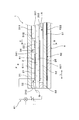
本例のガスセンサ素子1においては、図4、図5に示すように、被測定ガス空間51が、ポンプセル41が配置された第1ガス空間511と、センサセル42が配置された第2ガス空間512とによって構成されている。
本例のガスセンサ素子1においては、図4、図5に示すように、被測定ガス空間51が、ポンプセル41が配置された第1ガス空間511と、センサセル42が配置された第2ガス空間512とによって構成されている。
第1ガス空間511は、拡散抵抗体32が設けられた長手方向Lの一方側に形成されており、第2ガス空間512は、第1ガス空間511に隣接して、長手方向Lの他方側に形成されている。そして、被測定ガスGを第1ガス空間511にできるだけ長く滞留させるようにして、被測定ガスG中の残留酸素が第2ガス空間512におけるセンサ電極22へ流れにくくしている。
第1ガス空間511と第2ガス空間512とは、被測定ガスGの流れ方向Fにおける空間断面積を縮小する障害壁34によって仕切られた状態で連通されている。障害壁34は、固体電解質体2の被測定ガス空間51側の表面201から突出して設けられており、絶縁体31と障害壁34の端面との間には、被測定ガスGが通過するスリット(隙間)341が形成されている。
なお、第1ガス空間511と第2ガス空間512とは、障害壁34によって仕切る代わりに、ガスを透過させる性質を有する多孔質体によって仕切ることもできる。多孔質体は、第1ガス空間511と第2ガス空間512とを完全に仕切る状態で設けることができる。
本例のガスセンサ素子1のその他の構造及び図中の符号は、上記実施例1と同様であり、本例のガスセンサ素子1によっても上記実施例1と同様の作用効果を得ることができる。
本例のガスセンサ素子1のその他の構造及び図中の符号は、上記実施例1と同様であり、本例のガスセンサ素子1によっても上記実施例1と同様の作用効果を得ることができる。
(実施例3)
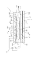
本例のガスセンサ素子1においては、図6、図7に示すように、第2ガス空間512には、ポンプセル41によって酸素濃度が調整された後の被測定ガスG中の酸素濃度をさらに調整する補助ポンプセル43が設けられている。
本例のガスセンサ素子1においては、図6、図7に示すように、第2ガス空間512には、ポンプセル41によって酸素濃度が調整された後の被測定ガスG中の酸素濃度をさらに調整する補助ポンプセル43が設けられている。
補助ポンプセル43は、固体電解質体2の被測定ガス空間51側の表面201に設けられた補助ポンプ電極23を有しており、補助ポンプ電極23と基準電極25との間に電圧を印加して、第2ガス空間512における酸素濃度を調整するよう構成されている。補助ポンプ電極23は、第2ガス空間512において、被測定ガスGの流れ方向Fにおけるセンサ電極22の配置位置よりも上流側の位置に設けられている。補助ポンプセル43を用いる場合には、補助ポンプセル43によって被測定ガスG中の残留酸素濃度をさらに調整され、NOx濃度の検出精度がさらに向上させる。
本例のガスセンサ素子1のその他の構造及び図中の符号は、上記実施例1と同様であり、本例のガスセンサ素子1によっても上記実施例1と同様の作用効果を得る。
Claims (3)
- 内燃機関の排気管に配置して、該排気管を流れる排気ガス中の所定ガス成分の濃度を検出するガスセンサ素子(1)であって、
酸素イオン伝導性を有する固体電解質体(2)と、
該固体電解質体(2)の一方の表面側に形成され、被測定ガス(G)としての上記排気ガスが拡散抵抗体(32)を通過して導入される被測定ガス空間(51)と、
上記固体電解質体(2)の他方の表面側に形成され、基準ガス(A)が導入される基準ガス空間(52)と、
上記固体電解質体(2)の上記被測定ガス空間(51)側の表面(201)に設けられたポンプ電極(21)を有し、該ポンプ電極(21)と上記固体電解質体(2)の上記基準ガス空間(52)側の表面(202)に設けられた基準電極(25)との間に電圧を印加して、上記被測定ガス空間(51)における酸素濃度を調整するポンプセル(41)と、
上記固体電解質体(2)の上記被測定ガス空間(51)側の表面(201)であって、上記被測定ガス(G)の流れ方向(F)における上記ポンプ電極(21)の配置位置よりも下流側の位置に設けられたセンサ電極(22)を有し、該センサ電極(22)と上記基準電極(25)との間に流れる酸素イオン電流を測定するセンサセル(42)と、を備え、
上記内燃機関において燃料の噴射が行われるときに上記センサセル(42)によって測定される酸素イオン電流値(I1)から、上記内燃機関において燃料の噴射が断絶された時から所定時間経過後に上記センサセル(42)によって測定される酸素イオン電流値(I2)を減算して、上記所定ガス成分の濃度を検出するよう構成されていることを特徴とするガスセンサ素子(1)。 - 上記被測定ガス空間(51)は、上記ポンプセル(41)が配置された第1ガス空間(511)と、上記センサセル(42)が配置された第2ガス空間(512)とによって構成されており、
上記第1ガス空間(511)と上記第2ガス空間(512)とは、上記被測定ガス(G)の流れ方向(F)における空間断面積を縮小する障害壁(34)、又はガスを透過させる性質を有する多孔質体によって仕切られた状態で連通されていることを特徴とする請求項1に記載のガスセンサ素子(1)。 - 上記第2ガス空間(512)には、上記ポンプセル(41)によって酸素濃度が調整された後の上記被測定ガス(G)中の酸素濃度をさらに調整する補助ポンプセル(43)が設けられており、
該補助ポンプセル(43)は、上記固体電解質体(2)の上記被測定ガス空間(51)側の表面(201)に設けられた補助ポンプ電極(23)を有し、該補助ポンプ電極(23)と上記基準電極(25)との間に電圧を印加して、上記第2ガス空間(512)における酸素濃度を調整するよう構成されていることを特徴とする請求項2に記載のガスセンサ素子(1)。
Priority Applications (2)
| Application Number | Priority Date | Filing Date | Title |
|---|---|---|---|
| US15/315,738 US10088446B2 (en) | 2014-06-04 | 2015-06-04 | Gas sensor |
| DE112015002626.6T DE112015002626T5 (de) | 2014-06-04 | 2015-06-04 | Gassensor |
Applications Claiming Priority (2)
| Application Number | Priority Date | Filing Date | Title |
|---|---|---|---|
| JP2014115994A JP6305832B2 (ja) | 2014-06-04 | 2014-06-04 | 特定ガス濃度検出方法 |
| JP2014-115994 | 2014-06-04 |
Publications (1)
| Publication Number | Publication Date |
|---|---|
| WO2015186776A1 true WO2015186776A1 (ja) | 2015-12-10 |
Family
ID=54766844
Family Applications (1)
| Application Number | Title | Priority Date | Filing Date |
|---|---|---|---|
| PCT/JP2015/066161 Ceased WO2015186776A1 (ja) | 2014-06-04 | 2015-06-04 | ガスセンサ素子 |
Country Status (4)
| Country | Link |
|---|---|
| US (1) | US10088446B2 (ja) |
| JP (1) | JP6305832B2 (ja) |
| DE (1) | DE112015002626T5 (ja) |
| WO (1) | WO2015186776A1 (ja) |
Cited By (1)
| Publication number | Priority date | Publication date | Assignee | Title |
|---|---|---|---|---|
| CN112857816A (zh) * | 2019-11-27 | 2021-05-28 | 通用电气公司 | 用于监测燃料氧转换单元的健康的方法及设备 |
Families Citing this family (3)
| Publication number | Priority date | Publication date | Assignee | Title |
|---|---|---|---|---|
| JP6560152B2 (ja) * | 2016-04-06 | 2019-08-14 | 日本特殊陶業株式会社 | ガスセンサ素子の劣化判定装置 |
| JP7010250B2 (ja) * | 2019-01-31 | 2022-01-26 | 株式会社デンソー | ガスセンサ |
| JP7006629B2 (ja) * | 2019-01-31 | 2022-01-24 | 株式会社デンソー | ガスセンサ |
Citations (8)
| Publication number | Priority date | Publication date | Assignee | Title |
|---|---|---|---|---|
| JPH09113484A (ja) * | 1995-10-20 | 1997-05-02 | Ngk Insulators Ltd | 被測定ガス中の所定ガス成分の測定方法及び測定装置 |
| JP2000321238A (ja) * | 1996-09-17 | 2000-11-24 | Riken Corp | ガスセンサ |
| JP2003149199A (ja) * | 2001-11-16 | 2003-05-21 | Nissan Motor Co Ltd | ガスセンサ |
| JP2004108788A (ja) * | 2002-09-13 | 2004-04-08 | Denso Corp | ガス濃度検出装置 |
| JP2005061884A (ja) * | 2003-08-20 | 2005-03-10 | Toyota Motor Corp | 濃度検出装置 |
| JP2006267127A (ja) * | 2006-06-05 | 2006-10-05 | Toyota Motor Corp | Noxセンサの故障診断装置 |
| JP2009150719A (ja) * | 2007-12-19 | 2009-07-09 | Toyota Motor Corp | Noxセンサ |
| JP2011058834A (ja) * | 2009-09-07 | 2011-03-24 | Denso Corp | ガスセンサ素子 |
Family Cites Families (9)
| Publication number | Priority date | Publication date | Assignee | Title |
|---|---|---|---|---|
| JP2001133429A (ja) * | 1999-11-01 | 2001-05-18 | Ngk Insulators Ltd | 車載用noxセンサのオフセット再校正方法 |
| JP3973900B2 (ja) * | 2001-02-08 | 2007-09-12 | 株式会社日本自動車部品総合研究所 | ガスセンサ素子 |
| JP4211232B2 (ja) * | 2001-04-19 | 2009-01-21 | トヨタ自動車株式会社 | 排気ガスセンサ |
| JP4374796B2 (ja) * | 2001-04-19 | 2009-12-02 | トヨタ自動車株式会社 | NOx濃度検出装置 |
| JP4304963B2 (ja) | 2002-11-08 | 2009-07-29 | 株式会社デンソー | ガスセンサ素子およびその製造方法 |
| JP2004251626A (ja) | 2003-02-18 | 2004-09-09 | Denso Corp | 内燃機関のガス濃度検出装置 |
| JP5074358B2 (ja) * | 2007-12-20 | 2012-11-14 | 日本特殊陶業株式会社 | ガスセンサ制御装置、及び窒素酸化物濃度検出方法 |
| JP2009175013A (ja) | 2008-01-24 | 2009-08-06 | Toyota Motor Corp | NOxセンサの劣化診断装置 |
| US10234420B2 (en) | 2013-09-20 | 2019-03-19 | Denso Corporation | Gas sensor control device |
-
2014
- 2014-06-04 JP JP2014115994A patent/JP6305832B2/ja active Active
-
2015
- 2015-06-04 WO PCT/JP2015/066161 patent/WO2015186776A1/ja not_active Ceased
- 2015-06-04 US US15/315,738 patent/US10088446B2/en active Active
- 2015-06-04 DE DE112015002626.6T patent/DE112015002626T5/de not_active Withdrawn
Patent Citations (8)
| Publication number | Priority date | Publication date | Assignee | Title |
|---|---|---|---|---|
| JPH09113484A (ja) * | 1995-10-20 | 1997-05-02 | Ngk Insulators Ltd | 被測定ガス中の所定ガス成分の測定方法及び測定装置 |
| JP2000321238A (ja) * | 1996-09-17 | 2000-11-24 | Riken Corp | ガスセンサ |
| JP2003149199A (ja) * | 2001-11-16 | 2003-05-21 | Nissan Motor Co Ltd | ガスセンサ |
| JP2004108788A (ja) * | 2002-09-13 | 2004-04-08 | Denso Corp | ガス濃度検出装置 |
| JP2005061884A (ja) * | 2003-08-20 | 2005-03-10 | Toyota Motor Corp | 濃度検出装置 |
| JP2006267127A (ja) * | 2006-06-05 | 2006-10-05 | Toyota Motor Corp | Noxセンサの故障診断装置 |
| JP2009150719A (ja) * | 2007-12-19 | 2009-07-09 | Toyota Motor Corp | Noxセンサ |
| JP2011058834A (ja) * | 2009-09-07 | 2011-03-24 | Denso Corp | ガスセンサ素子 |
Cited By (2)
| Publication number | Priority date | Publication date | Assignee | Title |
|---|---|---|---|---|
| CN112857816A (zh) * | 2019-11-27 | 2021-05-28 | 通用电气公司 | 用于监测燃料氧转换单元的健康的方法及设备 |
| CN112857816B (zh) * | 2019-11-27 | 2024-06-07 | 通用电气公司 | 用于监测燃料氧转换单元的健康的方法及设备 |
Also Published As
| Publication number | Publication date |
|---|---|
| DE112015002626T5 (de) | 2017-03-09 |
| US20170115250A1 (en) | 2017-04-27 |
| JP6305832B2 (ja) | 2018-04-04 |
| JP2015230220A (ja) | 2015-12-21 |
| US10088446B2 (en) | 2018-10-02 |
Similar Documents
| Publication | Publication Date | Title |
|---|---|---|
| JP6203687B2 (ja) | ガスセンサ | |
| JP5253165B2 (ja) | ガスセンサ及び窒素酸化物センサ | |
| US10921283B2 (en) | Gas sensor for detecting concentration of specific gas component | |
| CN105917219B (zh) | 气体传感器元件 | |
| JP5367044B2 (ja) | ガスセンサ素子および内燃機関用ガスセンサ | |
| JP5215482B2 (ja) | センサ制御装置 | |
| WO2015030165A1 (ja) | ガス濃度検出装置 | |
| JP3671109B2 (ja) | ガスセンサ | |
| US20110036715A1 (en) | Gas sensor | |
| JP6305832B2 (ja) | 特定ガス濃度検出方法 | |
| US20170191957A1 (en) | Gas sensor device | |
| JP6596535B2 (ja) | ガスセンサ | |
| WO2015029842A1 (ja) | ガス濃度検出装置 | |
| JP2015230220A5 (ja) | 特定ガス濃度検出方法 | |
| US6348140B1 (en) | Gas sensor with a high combined resistance to lead wire resistance ratio | |
| JP2013531251A (ja) | 測定ガス空間内のガスの特性を測定する装置 | |
| WO2015194490A1 (ja) | ガスセンサ | |
| US6805782B2 (en) | Compound layered type of sensing device for multiple measurement | |
| KR102605772B1 (ko) | 고체 전해질 가스 센서의 온도 결정 방법 | |
| JP6382178B2 (ja) | ガスセンサ | |
| JP6511405B2 (ja) | ガスセンサ | |
| JP6323181B2 (ja) | ガスセンサ素子 | |
| JP2017146199A (ja) | 硫黄酸化物検出装置 | |
| JP2018004349A (ja) | ガスセンサ | |
| JP2008134258A (ja) | ガスセンサ素子 |
Legal Events
| Date | Code | Title | Description |
|---|---|---|---|
| 121 | Ep: the epo has been informed by wipo that ep was designated in this application |
Ref document number: 15803024 Country of ref document: EP Kind code of ref document: A1 |
|
| WWE | Wipo information: entry into national phase |
Ref document number: 15315738 Country of ref document: US |
|
| WWE | Wipo information: entry into national phase |
Ref document number: 112015002626 Country of ref document: DE |
|
| 122 | Ep: pct application non-entry in european phase |
Ref document number: 15803024 Country of ref document: EP Kind code of ref document: A1 |