WO2015186571A1 - コージェライト焼結体、その製法、複合基板及び電子デバイス - Google Patents
コージェライト焼結体、その製法、複合基板及び電子デバイス Download PDFInfo
- Publication number
- WO2015186571A1 WO2015186571A1 PCT/JP2015/065096 JP2015065096W WO2015186571A1 WO 2015186571 A1 WO2015186571 A1 WO 2015186571A1 JP 2015065096 W JP2015065096 W JP 2015065096W WO 2015186571 A1 WO2015186571 A1 WO 2015186571A1
- Authority
- WO
- WIPO (PCT)
- Prior art keywords
- cordierite
- sintered body
- cordierite sintered
- substrate
- component
- Prior art date
- Legal status (The legal status is an assumption and is not a legal conclusion. Google has not performed a legal analysis and makes no representation as to the accuracy of the status listed.)
- Ceased
Links
Images


Classifications
-
- C—CHEMISTRY; METALLURGY
- C04—CEMENTS; CONCRETE; ARTIFICIAL STONE; CERAMICS; REFRACTORIES
- C04B—LIME, MAGNESIA; SLAG; CEMENTS; COMPOSITIONS THEREOF, e.g. MORTARS, CONCRETE OR LIKE BUILDING MATERIALS; ARTIFICIAL STONE; CERAMICS; REFRACTORIES; TREATMENT OF NATURAL STONE
- C04B35/00—Shaped ceramic products characterised by their composition; Ceramics compositions; Processing powders of inorganic compounds preparatory to the manufacturing of ceramic products
- C04B35/01—Shaped ceramic products characterised by their composition; Ceramics compositions; Processing powders of inorganic compounds preparatory to the manufacturing of ceramic products based on oxide ceramics
- C04B35/16—Shaped ceramic products characterised by their composition; Ceramics compositions; Processing powders of inorganic compounds preparatory to the manufacturing of ceramic products based on oxide ceramics based on silicates other than clay
- C04B35/18—Shaped ceramic products characterised by their composition; Ceramics compositions; Processing powders of inorganic compounds preparatory to the manufacturing of ceramic products based on oxide ceramics based on silicates other than clay rich in aluminium oxide
- C04B35/195—Alkaline earth aluminosilicates, e.g. cordierite or anorthite
-
- C—CHEMISTRY; METALLURGY
- C04—CEMENTS; CONCRETE; ARTIFICIAL STONE; CERAMICS; REFRACTORIES
- C04B—LIME, MAGNESIA; SLAG; CEMENTS; COMPOSITIONS THEREOF, e.g. MORTARS, CONCRETE OR LIKE BUILDING MATERIALS; ARTIFICIAL STONE; CERAMICS; REFRACTORIES; TREATMENT OF NATURAL STONE
- C04B35/00—Shaped ceramic products characterised by their composition; Ceramics compositions; Processing powders of inorganic compounds preparatory to the manufacturing of ceramic products
- C04B35/622—Forming processes; Processing powders of inorganic compounds preparatory to the manufacturing of ceramic products
- C04B35/64—Burning or sintering processes
- C04B35/645—Pressure sintering
- C04B35/6455—Hot isostatic pressing
-
- C—CHEMISTRY; METALLURGY
- C04—CEMENTS; CONCRETE; ARTIFICIAL STONE; CERAMICS; REFRACTORIES
- C04B—LIME, MAGNESIA; SLAG; CEMENTS; COMPOSITIONS THEREOF, e.g. MORTARS, CONCRETE OR LIKE BUILDING MATERIALS; ARTIFICIAL STONE; CERAMICS; REFRACTORIES; TREATMENT OF NATURAL STONE
- C04B37/00—Joining burned ceramic articles with other burned ceramic articles or other articles by heating
-
- C—CHEMISTRY; METALLURGY
- C30—CRYSTAL GROWTH
- C30B—SINGLE-CRYSTAL GROWTH; UNIDIRECTIONAL SOLIDIFICATION OF EUTECTIC MATERIAL OR UNIDIRECTIONAL DEMIXING OF EUTECTOID MATERIAL; REFINING BY ZONE-MELTING OF MATERIAL; PRODUCTION OF A HOMOGENEOUS POLYCRYSTALLINE MATERIAL WITH DEFINED STRUCTURE; SINGLE CRYSTALS OR HOMOGENEOUS POLYCRYSTALLINE MATERIAL WITH DEFINED STRUCTURE; AFTER-TREATMENT OF SINGLE CRYSTALS OR A HOMOGENEOUS POLYCRYSTALLINE MATERIAL WITH DEFINED STRUCTURE; APPARATUS THEREFOR
- C30B33/00—After-treatment of single crystals or homogeneous polycrystalline material with defined structure
- C30B33/06—Joining of crystals
-
- C—CHEMISTRY; METALLURGY
- C04—CEMENTS; CONCRETE; ARTIFICIAL STONE; CERAMICS; REFRACTORIES
- C04B—LIME, MAGNESIA; SLAG; CEMENTS; COMPOSITIONS THEREOF, e.g. MORTARS, CONCRETE OR LIKE BUILDING MATERIALS; ARTIFICIAL STONE; CERAMICS; REFRACTORIES; TREATMENT OF NATURAL STONE
- C04B2235/00—Aspects relating to ceramic starting mixtures or sintered ceramic products
- C04B2235/02—Composition of constituents of the starting material or of secondary phases of the final product
- C04B2235/30—Constituents and secondary phases not being of a fibrous nature
- C04B2235/32—Metal oxides, mixed metal oxides, or oxide-forming salts thereof, e.g. carbonates, nitrates, (oxy)hydroxides, chlorides
- C04B2235/3205—Alkaline earth oxides or oxide forming salts thereof, e.g. beryllium oxide
- C04B2235/3206—Magnesium oxides or oxide-forming salts thereof
-
- C—CHEMISTRY; METALLURGY
- C04—CEMENTS; CONCRETE; ARTIFICIAL STONE; CERAMICS; REFRACTORIES
- C04B—LIME, MAGNESIA; SLAG; CEMENTS; COMPOSITIONS THEREOF, e.g. MORTARS, CONCRETE OR LIKE BUILDING MATERIALS; ARTIFICIAL STONE; CERAMICS; REFRACTORIES; TREATMENT OF NATURAL STONE
- C04B2235/00—Aspects relating to ceramic starting mixtures or sintered ceramic products
- C04B2235/02—Composition of constituents of the starting material or of secondary phases of the final product
- C04B2235/30—Constituents and secondary phases not being of a fibrous nature
- C04B2235/32—Metal oxides, mixed metal oxides, or oxide-forming salts thereof, e.g. carbonates, nitrates, (oxy)hydroxides, chlorides
- C04B2235/3217—Aluminum oxide or oxide forming salts thereof, e.g. bauxite, alpha-alumina
-
- C—CHEMISTRY; METALLURGY
- C04—CEMENTS; CONCRETE; ARTIFICIAL STONE; CERAMICS; REFRACTORIES
- C04B—LIME, MAGNESIA; SLAG; CEMENTS; COMPOSITIONS THEREOF, e.g. MORTARS, CONCRETE OR LIKE BUILDING MATERIALS; ARTIFICIAL STONE; CERAMICS; REFRACTORIES; TREATMENT OF NATURAL STONE
- C04B2235/00—Aspects relating to ceramic starting mixtures or sintered ceramic products
- C04B2235/02—Composition of constituents of the starting material or of secondary phases of the final product
- C04B2235/30—Constituents and secondary phases not being of a fibrous nature
- C04B2235/32—Metal oxides, mixed metal oxides, or oxide-forming salts thereof, e.g. carbonates, nitrates, (oxy)hydroxides, chlorides
- C04B2235/327—Iron group oxides, their mixed metal oxides, or oxide-forming salts thereof
- C04B2235/3272—Iron oxides or oxide forming salts thereof, e.g. hematite, magnetite
-
- C—CHEMISTRY; METALLURGY
- C04—CEMENTS; CONCRETE; ARTIFICIAL STONE; CERAMICS; REFRACTORIES
- C04B—LIME, MAGNESIA; SLAG; CEMENTS; COMPOSITIONS THEREOF, e.g. MORTARS, CONCRETE OR LIKE BUILDING MATERIALS; ARTIFICIAL STONE; CERAMICS; REFRACTORIES; TREATMENT OF NATURAL STONE
- C04B2235/00—Aspects relating to ceramic starting mixtures or sintered ceramic products
- C04B2235/02—Composition of constituents of the starting material or of secondary phases of the final product
- C04B2235/30—Constituents and secondary phases not being of a fibrous nature
- C04B2235/34—Non-metal oxides, non-metal mixed oxides, or salts thereof that form the non-metal oxides upon heating, e.g. carbonates, nitrates, (oxy)hydroxides, chlorides
- C04B2235/3418—Silicon oxide, silicic acids or oxide forming salts thereof, e.g. silica sol, fused silica, silica fume, cristobalite, quartz or flint
-
- C—CHEMISTRY; METALLURGY
- C04—CEMENTS; CONCRETE; ARTIFICIAL STONE; CERAMICS; REFRACTORIES
- C04B—LIME, MAGNESIA; SLAG; CEMENTS; COMPOSITIONS THEREOF, e.g. MORTARS, CONCRETE OR LIKE BUILDING MATERIALS; ARTIFICIAL STONE; CERAMICS; REFRACTORIES; TREATMENT OF NATURAL STONE
- C04B2235/00—Aspects relating to ceramic starting mixtures or sintered ceramic products
- C04B2235/02—Composition of constituents of the starting material or of secondary phases of the final product
- C04B2235/30—Constituents and secondary phases not being of a fibrous nature
- C04B2235/34—Non-metal oxides, non-metal mixed oxides, or salts thereof that form the non-metal oxides upon heating, e.g. carbonates, nitrates, (oxy)hydroxides, chlorides
- C04B2235/3427—Silicates other than clay, e.g. water glass
- C04B2235/3463—Alumino-silicates other than clay, e.g. mullite
- C04B2235/3481—Alkaline earth metal alumino-silicates other than clay, e.g. cordierite, beryl, micas such as margarite, plagioclase feldspars such as anorthite, zeolites such as chabazite
-
- C—CHEMISTRY; METALLURGY
- C04—CEMENTS; CONCRETE; ARTIFICIAL STONE; CERAMICS; REFRACTORIES
- C04B—LIME, MAGNESIA; SLAG; CEMENTS; COMPOSITIONS THEREOF, e.g. MORTARS, CONCRETE OR LIKE BUILDING MATERIALS; ARTIFICIAL STONE; CERAMICS; REFRACTORIES; TREATMENT OF NATURAL STONE
- C04B2235/00—Aspects relating to ceramic starting mixtures or sintered ceramic products
- C04B2235/02—Composition of constituents of the starting material or of secondary phases of the final product
- C04B2235/50—Constituents or additives of the starting mixture chosen for their shape or used because of their shape or their physical appearance
- C04B2235/54—Particle size related information
- C04B2235/5418—Particle size related information expressed by the size of the particles or aggregates thereof
- C04B2235/5445—Particle size related information expressed by the size of the particles or aggregates thereof submicron sized, i.e. from 0,1 to 1 micron
-
- C—CHEMISTRY; METALLURGY
- C04—CEMENTS; CONCRETE; ARTIFICIAL STONE; CERAMICS; REFRACTORIES
- C04B—LIME, MAGNESIA; SLAG; CEMENTS; COMPOSITIONS THEREOF, e.g. MORTARS, CONCRETE OR LIKE BUILDING MATERIALS; ARTIFICIAL STONE; CERAMICS; REFRACTORIES; TREATMENT OF NATURAL STONE
- C04B2235/00—Aspects relating to ceramic starting mixtures or sintered ceramic products
- C04B2235/65—Aspects relating to heat treatments of ceramic bodies such as green ceramics or pre-sintered ceramics, e.g. burning, sintering or melting processes
- C04B2235/656—Aspects relating to heat treatments of ceramic bodies such as green ceramics or pre-sintered ceramics, e.g. burning, sintering or melting processes characterised by specific heating conditions during heat treatment
- C04B2235/6562—Heating rate
-
- C—CHEMISTRY; METALLURGY
- C04—CEMENTS; CONCRETE; ARTIFICIAL STONE; CERAMICS; REFRACTORIES
- C04B—LIME, MAGNESIA; SLAG; CEMENTS; COMPOSITIONS THEREOF, e.g. MORTARS, CONCRETE OR LIKE BUILDING MATERIALS; ARTIFICIAL STONE; CERAMICS; REFRACTORIES; TREATMENT OF NATURAL STONE
- C04B2235/00—Aspects relating to ceramic starting mixtures or sintered ceramic products
- C04B2235/65—Aspects relating to heat treatments of ceramic bodies such as green ceramics or pre-sintered ceramics, e.g. burning, sintering or melting processes
- C04B2235/656—Aspects relating to heat treatments of ceramic bodies such as green ceramics or pre-sintered ceramics, e.g. burning, sintering or melting processes characterised by specific heating conditions during heat treatment
- C04B2235/6565—Cooling rate
-
- C—CHEMISTRY; METALLURGY
- C04—CEMENTS; CONCRETE; ARTIFICIAL STONE; CERAMICS; REFRACTORIES
- C04B—LIME, MAGNESIA; SLAG; CEMENTS; COMPOSITIONS THEREOF, e.g. MORTARS, CONCRETE OR LIKE BUILDING MATERIALS; ARTIFICIAL STONE; CERAMICS; REFRACTORIES; TREATMENT OF NATURAL STONE
- C04B2235/00—Aspects relating to ceramic starting mixtures or sintered ceramic products
- C04B2235/65—Aspects relating to heat treatments of ceramic bodies such as green ceramics or pre-sintered ceramics, e.g. burning, sintering or melting processes
- C04B2235/656—Aspects relating to heat treatments of ceramic bodies such as green ceramics or pre-sintered ceramics, e.g. burning, sintering or melting processes characterised by specific heating conditions during heat treatment
- C04B2235/6567—Treatment time
-
- C—CHEMISTRY; METALLURGY
- C04—CEMENTS; CONCRETE; ARTIFICIAL STONE; CERAMICS; REFRACTORIES
- C04B—LIME, MAGNESIA; SLAG; CEMENTS; COMPOSITIONS THEREOF, e.g. MORTARS, CONCRETE OR LIKE BUILDING MATERIALS; ARTIFICIAL STONE; CERAMICS; REFRACTORIES; TREATMENT OF NATURAL STONE
- C04B2235/00—Aspects relating to ceramic starting mixtures or sintered ceramic products
- C04B2235/65—Aspects relating to heat treatments of ceramic bodies such as green ceramics or pre-sintered ceramics, e.g. burning, sintering or melting processes
- C04B2235/66—Specific sintering techniques, e.g. centrifugal sintering
- C04B2235/661—Multi-step sintering
- C04B2235/662—Annealing after sintering
-
- C—CHEMISTRY; METALLURGY
- C04—CEMENTS; CONCRETE; ARTIFICIAL STONE; CERAMICS; REFRACTORIES
- C04B—LIME, MAGNESIA; SLAG; CEMENTS; COMPOSITIONS THEREOF, e.g. MORTARS, CONCRETE OR LIKE BUILDING MATERIALS; ARTIFICIAL STONE; CERAMICS; REFRACTORIES; TREATMENT OF NATURAL STONE
- C04B2235/00—Aspects relating to ceramic starting mixtures or sintered ceramic products
- C04B2235/70—Aspects relating to sintered or melt-casted ceramic products
- C04B2235/72—Products characterised by the absence or the low content of specific components, e.g. alkali metal free alumina ceramics
-
- C—CHEMISTRY; METALLURGY
- C04—CEMENTS; CONCRETE; ARTIFICIAL STONE; CERAMICS; REFRACTORIES
- C04B—LIME, MAGNESIA; SLAG; CEMENTS; COMPOSITIONS THEREOF, e.g. MORTARS, CONCRETE OR LIKE BUILDING MATERIALS; ARTIFICIAL STONE; CERAMICS; REFRACTORIES; TREATMENT OF NATURAL STONE
- C04B2235/00—Aspects relating to ceramic starting mixtures or sintered ceramic products
- C04B2235/70—Aspects relating to sintered or melt-casted ceramic products
- C04B2235/74—Physical characteristics
- C04B2235/76—Crystal structural characteristics, e.g. symmetry
-
- C—CHEMISTRY; METALLURGY
- C04—CEMENTS; CONCRETE; ARTIFICIAL STONE; CERAMICS; REFRACTORIES
- C04B—LIME, MAGNESIA; SLAG; CEMENTS; COMPOSITIONS THEREOF, e.g. MORTARS, CONCRETE OR LIKE BUILDING MATERIALS; ARTIFICIAL STONE; CERAMICS; REFRACTORIES; TREATMENT OF NATURAL STONE
- C04B2235/00—Aspects relating to ceramic starting mixtures or sintered ceramic products
- C04B2235/70—Aspects relating to sintered or melt-casted ceramic products
- C04B2235/74—Physical characteristics
- C04B2235/77—Density
-
- C—CHEMISTRY; METALLURGY
- C04—CEMENTS; CONCRETE; ARTIFICIAL STONE; CERAMICS; REFRACTORIES
- C04B—LIME, MAGNESIA; SLAG; CEMENTS; COMPOSITIONS THEREOF, e.g. MORTARS, CONCRETE OR LIKE BUILDING MATERIALS; ARTIFICIAL STONE; CERAMICS; REFRACTORIES; TREATMENT OF NATURAL STONE
- C04B2235/00—Aspects relating to ceramic starting mixtures or sintered ceramic products
- C04B2235/70—Aspects relating to sintered or melt-casted ceramic products
- C04B2235/74—Physical characteristics
- C04B2235/78—Grain sizes and shapes, product microstructures, e.g. acicular grains, equiaxed grains, platelet-structures
-
- C—CHEMISTRY; METALLURGY
- C04—CEMENTS; CONCRETE; ARTIFICIAL STONE; CERAMICS; REFRACTORIES
- C04B—LIME, MAGNESIA; SLAG; CEMENTS; COMPOSITIONS THEREOF, e.g. MORTARS, CONCRETE OR LIKE BUILDING MATERIALS; ARTIFICIAL STONE; CERAMICS; REFRACTORIES; TREATMENT OF NATURAL STONE
- C04B2235/00—Aspects relating to ceramic starting mixtures or sintered ceramic products
- C04B2235/70—Aspects relating to sintered or melt-casted ceramic products
- C04B2235/80—Phases present in the sintered or melt-cast ceramic products other than the main phase
-
- C—CHEMISTRY; METALLURGY
- C04—CEMENTS; CONCRETE; ARTIFICIAL STONE; CERAMICS; REFRACTORIES
- C04B—LIME, MAGNESIA; SLAG; CEMENTS; COMPOSITIONS THEREOF, e.g. MORTARS, CONCRETE OR LIKE BUILDING MATERIALS; ARTIFICIAL STONE; CERAMICS; REFRACTORIES; TREATMENT OF NATURAL STONE
- C04B2235/00—Aspects relating to ceramic starting mixtures or sintered ceramic products
- C04B2235/70—Aspects relating to sintered or melt-casted ceramic products
- C04B2235/96—Properties of ceramic products, e.g. mechanical properties such as strength, toughness, wear resistance
- C04B2235/963—Surface properties, e.g. surface roughness
-
- C—CHEMISTRY; METALLURGY
- C04—CEMENTS; CONCRETE; ARTIFICIAL STONE; CERAMICS; REFRACTORIES
- C04B—LIME, MAGNESIA; SLAG; CEMENTS; COMPOSITIONS THEREOF, e.g. MORTARS, CONCRETE OR LIKE BUILDING MATERIALS; ARTIFICIAL STONE; CERAMICS; REFRACTORIES; TREATMENT OF NATURAL STONE
- C04B2235/00—Aspects relating to ceramic starting mixtures or sintered ceramic products
- C04B2235/70—Aspects relating to sintered or melt-casted ceramic products
- C04B2235/96—Properties of ceramic products, e.g. mechanical properties such as strength, toughness, wear resistance
- C04B2235/9646—Optical properties
-
- C—CHEMISTRY; METALLURGY
- C04—CEMENTS; CONCRETE; ARTIFICIAL STONE; CERAMICS; REFRACTORIES
- C04B—LIME, MAGNESIA; SLAG; CEMENTS; COMPOSITIONS THEREOF, e.g. MORTARS, CONCRETE OR LIKE BUILDING MATERIALS; ARTIFICIAL STONE; CERAMICS; REFRACTORIES; TREATMENT OF NATURAL STONE
- C04B2237/00—Aspects relating to ceramic laminates or to joining of ceramic articles with other articles by heating
- C04B2237/30—Composition of layers of ceramic laminates or of ceramic or metallic articles to be joined by heating, e.g. Si substrates
-
- C—CHEMISTRY; METALLURGY
- C04—CEMENTS; CONCRETE; ARTIFICIAL STONE; CERAMICS; REFRACTORIES
- C04B—LIME, MAGNESIA; SLAG; CEMENTS; COMPOSITIONS THEREOF, e.g. MORTARS, CONCRETE OR LIKE BUILDING MATERIALS; ARTIFICIAL STONE; CERAMICS; REFRACTORIES; TREATMENT OF NATURAL STONE
- C04B2237/00—Aspects relating to ceramic laminates or to joining of ceramic articles with other articles by heating
- C04B2237/50—Processing aspects relating to ceramic laminates or to the joining of ceramic articles with other articles by heating
- C04B2237/52—Pre-treatment of the joining surfaces, e.g. cleaning, machining
-
- C—CHEMISTRY; METALLURGY
- C04—CEMENTS; CONCRETE; ARTIFICIAL STONE; CERAMICS; REFRACTORIES
- C04B—LIME, MAGNESIA; SLAG; CEMENTS; COMPOSITIONS THEREOF, e.g. MORTARS, CONCRETE OR LIKE BUILDING MATERIALS; ARTIFICIAL STONE; CERAMICS; REFRACTORIES; TREATMENT OF NATURAL STONE
- C04B2237/00—Aspects relating to ceramic laminates or to joining of ceramic articles with other articles by heating
- C04B2237/50—Processing aspects relating to ceramic laminates or to the joining of ceramic articles with other articles by heating
- C04B2237/55—Pre-treatments of a coated or not coated substrate other than oxidation treatment in order to form an active joining layer
-
- H—ELECTRICITY
- H03—ELECTRONIC CIRCUITRY
- H03H—IMPEDANCE NETWORKS, e.g. RESONANT CIRCUITS; RESONATORS
- H03H9/00—Networks comprising electromechanical or electro-acoustic elements; Electromechanical resonators
- H03H9/02—Details
- H03H9/02535—Details of surface acoustic wave devices
- H03H9/02543—Characteristics of substrate, e.g. cutting angles
- H03H9/02574—Characteristics of substrate, e.g. cutting angles of combined substrates, multilayered substrates, piezoelectrical layers on not-piezoelectrical substrate
-
- H—ELECTRICITY
- H03—ELECTRONIC CIRCUITRY
- H03H—IMPEDANCE NETWORKS, e.g. RESONANT CIRCUITS; RESONATORS
- H03H9/00—Networks comprising electromechanical or electro-acoustic elements; Electromechanical resonators
- H03H9/02—Details
- H03H9/02535—Details of surface acoustic wave devices
- H03H9/02818—Means for compensation or elimination of undesirable effects
- H03H9/02834—Means for compensation or elimination of undesirable effects of temperature influence
Definitions
- the present invention relates to a cordierite sintered body, a manufacturing method thereof, a composite substrate, and an electronic device.
- Cordierite sintered body is a material with high heat resistance and low coefficient of thermal expansion, so it is known as a material with high thermal shock.
- a porous sintered structure is used to purify exhaust gas from automobiles, etc. It is widely used as a catalyst carrier and filter.
- the dense cordierite sintered body also makes use of the features of low thermal expansion and light weight.
- it has been used as a stage member for an exposure apparatus (Patent Document 1) and an ultra-precision mirror substrate (Patent Document 2). Is underway.
- Patent Document 1 in order to obtain particularly high rigidity, the CaO content in the cordierite sintered body is set to 0.2 to 0.8% by mass, and a predetermined amount of Al 2 O 3 is contained as a sub-crystal. It is carried out.
- CaO has the effect of improving Young's modulus by promoting the grain growth and sinterability of cordierite, and Al 2 O 3 is said to have the effect of suppressing and densifying the abnormal grain growth of cordierite.
- Patent Document 2 the problem is to reduce the surface roughness in addition to high rigidity, and a specific amount of a specific rare earth metal component is added as a sintering aid to produce a dense cordierite sintered body.
- the obtained sintered body does not contain a crystalline phase other than cordierite, and the rare earth metal-containing component is present in the form of a film along the grain boundary of the cordierite particles as an amorphous phase. It is said that the absence of crystal components other than cordierite can avoid the occurrence of irregularities due to the difference in polishing characteristics between different particles.
- Patent Document 3 As an example of producing a dense cordierite sintered body without adding a sintering aid, there is Patent Document 3.
- a compact obtained by uniaxial die press molding of cordierite powder having an average particle size of 0.7 ⁇ m or less was fired at 1400 ° C. for 12 hours in a nitrogen atmosphere, and the cordierite content was 97.6% by mass.
- a cordierite sintered body having features such as a bulk density of 2.54 g / cm 3 , an open porosity of 0%, a total porosity of 0.1%, and having mullite, spinel, and sapphirine in a different phase has been produced (implementation) Example 1).
- This sintered body has a closed porosity of 0.1% based on the total porosity and open porosity, and the major axis has a major axis on the surface of about 20 ⁇ m 2 from the photograph after thermal etching of the polished surface shown in FIG. It can be seen that there are about 20 closed pores of about 0.2 to 0.5 ⁇ m.
- Patent Document 4 discloses a surface acoustic wave element in which a main substrate made of lithium tantalate, lithium niobate, or the like and an auxiliary substrate made of glass or silicon are directly bonded.
- the thermal expansion coefficient of the auxiliary substrate is smaller than that of the main substrate, and the thickness of the auxiliary substrate is thicker than that of the main substrate.
- Patent Document 5 describes a technique for improving the temperature dependence of a surface acoustic wave element, as in Patent Document 4.
- the piezoelectric substrate (main substrate) is either lithium tantalate or lithium niobate
- the support substrate (auxiliary substrate) is one of sapphire, aluminum oxide, aluminum nitride, or silicon nitride (thermal expansion coefficient 2.6 ppm / ° C.).
- the bonded substrate is manufactured by direct bonding. However, there is no description about the surface condition required for the support substrate or the like.
- a polycrystalline material such as aluminum oxide, aluminum nitride, or silicon nitride is used as the support substrate. Is not described at all, and the degree of surface flatness is unknown.
- the ratio of the total peak intensity of each component other than the cordierite component to the peak top intensity of the (110) plane of cordierite is 0.0025. It is as follows. Since this cordierite sintered body has very few foreign phases other than the cordierite component, the surface flatness is enhanced when the surface is polished into a mirror surface.
- the method for producing a cordierite sintered body of the present invention includes a cordierite sintered body obtained by sintering a cordierite raw material powder containing an MgO component, an Al 2 O 3 component and an SiO 2 component in an inert atmosphere by a hot press method.
- the cordierite raw material powder has a molar ratio of MgO / Al 2 O 3 of 0.96 to 1.04 and a molar ratio of SiO 2 / Al 2 O 3 of 2.46 to 2.4. 54, MgO, SiO 2 and Al 2 O 3 occupy a total proportion of 99.9% by mass and the average particle size D50 is 1 ⁇ m or less.
- Conditions for sintering by the hot press method are as follows: The pressing pressure is 20 to 300 kgf / cm 2 and the firing temperature is 1410 to 1450 ° C. This manufacturing method is suitable for manufacturing the above-described cordierite sintered body of the present invention.
- the composite substrate of the present invention is obtained by bonding a functional substrate and a support substrate made of a cordierite sintered body, and the ratio of the area actually bonded in the bonded interface (bonded area ratio) is 80% or more.
- the bonding area ratio is increased in this way, and good bondability is exhibited.
- the electronic device of the present invention uses the above-described composite substrate.
- the thermal expansion coefficient of the cordierite sintered body as the supporting substrate is as small as about 1.1 ppm / K (40-400 ° C.)
- the frequency temperature dependency when the surface acoustic wave device is used is high.
- the performance is improved because the thermal expansion coefficient of the support substrate is very small.
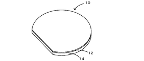
- FIG. 1 is a perspective view of a composite substrate 10.
- the ratio of the total peak intensity of each component other than the cordierite component to the peak top intensity of the (110) plane of cordierite is 0.0025. It is as follows.
- the center line average roughness Ra in the 10 ⁇ m square measurement range is 1 nm or less
- the maximum peak height Rp in the 70 ⁇ m square measurement range is Is preferably 30 nm or less, and at least one of the number of pores having a maximum length of 0.1 ⁇ m or more in an arbitrary 4 ⁇ m ⁇ 4 ⁇ m range is 10 or less.
- the ease of polishing differs between cordierite and the different phase components.
- the different phase components are difficult to be polished and remain in a convex shape, the surface flatness is not sufficiently high.
- the cordierite sintered body of the present invention has a molar ratio of MgO / Al 2 O 3 of 0.96 to 1.04 and a molar ratio of SiO 2 / Al 2 O 3 of 2.46 to 2.54. preferable. Further, the proportion of the three components of MgO, Al 2 O 3 and SiO 2 is 99.9% by mass or more, in other words, the proportion of components other than these three components is less than 0.1% by mass. Preferably there is. Furthermore, the average particle size of the cordierite sintered particles is preferably 1 ⁇ m or less. Furthermore, the bulk density is preferably 2.495 to 2.515 g / cm 3 (the true density is 2.505 g / cm 3 ). By doing in this way, the heterogeneous component in a cordierite sintered compact can be decreased further.
- the total transmittance and linear transmittance for light having a wavelength of 550 nm are preferably 60% or more and 50% or more, respectively, and 70% or more and 60% or more, respectively. More preferred.
- the cordierite sintered body of the present invention can be used as a material for heat-resistant and translucent equipment such as a high-temperature furnace window material and a condenser furnace reaction tube because of the high thermal stability and thermal shock resistance of cordierite. It is. Conventionally, quartz glass and translucent alumina are used as such materials.
- quartz glass needs to be used at 1000 ° C. or lower.
- translucent alumina can be used at 1000 ° C. or higher, but care for thermal shock is necessary.
- the cordierite sintered body of the present invention has high heat resistance compared to quartz glass and can be used at 1000 ° C. or higher, and has high thermal shock resistance compared to translucent alumina. It is not necessary to provide care and can be used as a material for heat-resistant and translucent devices. Further, the light transmissivity and transparency can be further improved by annealing the cordierite sintered body at 1200 to 1400 ° C.
- the production flow of the cordierite sintered body includes a step of producing a cordierite raw material powder and a step of producing a cordierite sintered body.
- the mixed powder in which the MgO component, the Al 2 O 3 component, and the SiO 2 component are blended at a predetermined ratio is fired to obtain a cordierite coarse particle (S1 in FIG. 1).
- the mixed powder means a powder obtained by mixing three components that become cordierite by firing.
- the MgO component is 13.8% by mass
- the Al 2 O 3 component is 34.9% by mass
- the SiO 2 component is A mixed powder blended so as to be 51.3% by mass is preferable.
- the amount of the component mixed in the pulverization process can be assumed in advance, for example, when the amount of the alumina component mixed from the alumina media (alumina ball, alumina pot, etc.) used in the pulverization process can be assumed, Al mixed into the mixed powder
- the amount of 2 O 3 component may be reduced.
- components that are scattered by heating, such as CO 2 and H 2 O are not included in the impurities.
- the cordierite coarse particles obtained by firing the mixed powder are pulverized to produce a cordierite pulverized product (S2 in FIG. 1).
- the mixed powder can be fired, for example, by heating to 1300 to 1450 ° C. in an air atmosphere.
- the average particle size (D50) of the cordierite pulverized product is pulverized to 2 ⁇ m or less, preferably 1 ⁇ m or less, and more preferably 0.8 ⁇ m or less.
- the average particle size of the cordierite pulverized product is preferably 0.1 ⁇ m or more, and more preferably 0.3 ⁇ m or more.
- the average particle diameter can be measured by a laser diffraction method.
- the grinding method there is no particular limitation on the grinding method, and for example, a ball mill, an attritor, a bead mill, a jet mill or the like can be used.
- alumina cobblestones or pots that do not become impurities even if mixed in the media.
- resin pots and cobblestones can be used because they can be removed in the firing step or the like, but when using cobblestones, a long time is required for crushing.
- media made of zirconia it is necessary to shorten the pulverization time, and in particular to prevent a large amount of contamination. Metal media is not preferred because the amount of impurities increases.
- the cordierite pulverized product is dried, and the dried cordierite pulverized product is analyzed for the MgO component amount, the Al 2 O 3 component amount, and the SiO 2 component amount so that the proportion of each component matches the cordierite composition.
- a necessary amount of a necessary component is added to the dried cordierite pulverized product to obtain a cordierite raw material powder (S3 in FIG. 1). For example, when cordierite coarse particles are pulverized with alumina media, the amount of Al 2 O 3 component is excessive with respect to the cordierite composition.
- a predetermined amount of MgO powder and SiO 2 powder are added to the dried cordierite pulverized product and readjusted to obtain a cordierite composition, and the readjusted powder is used as a cordierite raw material powder.
- the re-adjusted powder is also subjected to a mixing process similar to the pulverization process, but at this time, it is important to shorten the mixing time in order to suppress mixing from the media.
- the dried cordierite pulverized product is used as it is. It is good also as raw material powder.
- the Al 2 O 3 component of the mixed powder may be previously and weight loss. If it carries out like this, the cordierite ground material after drying can be used as a cordierite raw material powder as it is. In this way, a high-purity cordierite raw material powder whose composition and powder particle size are adjusted is prepared.
- the cordierite raw material powder thus obtained has an MgO / Al 2 O 3 molar ratio of 0.96 to 1.04 and an SiO 2 / Al 2 O 3 molar ratio of 2.46 to 2.4, for example. 54, MgO, SiO 2 and Al 2 O 3 account for 99.9% by mass or more and the average particle diameter D50 is 1 ⁇ m or less.
- the obtained cordierite raw material powder is formed into a predetermined shape (S4 in FIG. 1).
- molding method can be used.
- the cordierite raw material powder as described above may be directly press-molded with a mold.
- press molding if the cordierite raw material powder is granulated by spray drying, the moldability is improved.
- an organic binder can be added to produce clay and extrusion molding, or a slurry can be produced and sheet molded. In these processes, it is necessary to remove the organic binder component before or during the firing step. Further, high pressure molding may be performed by CIP (cold isostatic pressing).
- a hot press method is very effective as the method.
- the firing temperature during this hot pressing is preferably 1410 to 1450 ° C., and more preferably 1420 to 1440 ° C. in order to minimize the number of different phases.
- the pressing pressure during hot pressing is preferably 20 to 300 kgf / cm 2 . Particularly, a low pressing pressure is more preferable because the hot pressing jig can be reduced in size and extended in life.
- the holding time at the firing temperature can be appropriately selected in consideration of the shape and size of the molded body and the characteristics of the heating furnace. A specific preferable holding time is, for example, 1 to 12 hours, and more preferably 2 to 8 hours.
- the firing atmosphere and the atmosphere during hot pressing is generally an inert atmosphere such as nitrogen or argon.
- the composite substrate of the present invention is obtained by bonding a functional substrate and a support substrate made of a cordierite sintered body, and the ratio of the area actually bonded in the bonded interface (bonded area ratio) is 80% or more.
- the bonding area ratio is increased in this way, and good bondability is exhibited.
- the functional substrate is not particularly limited, and examples thereof include lithium tantalate, lithium niobate, gallium nitride, and silicon.
- the bonding method may be direct bonding or bonding via an adhesive layer, but direct bonding is preferable.
- both the substrates are pressed in a state where both the bonding surfaces face each other.
- the bonding surface is activated by, for example, irradiation of an ion beam of an inert gas (such as argon) to the bonding surface, or irradiation of plasma or a neutral atom beam.
- an adhesive layer for example, an epoxy resin or an acrylic resin is used as the adhesive layer.
- the ratio of the thickness of the functional substrate to the support substrate is preferably 0.1 or less.
- FIG. 2 shows an example of the composite substrate.
- the composite substrate 10 is obtained by bonding a piezoelectric substrate 12 which is a functional substrate and a support substrate 14 by direct bonding.
- the electronic device of the present invention uses the above-described composite substrate.
- Examples of such electronic devices include acoustic wave devices (such as surface acoustic wave devices, Lamb wave elements, and thin film resonators (FBAR)), LED devices, optical waveguide devices, and switch devices.
- acoustic wave devices such as surface acoustic wave devices, Lamb wave elements, and thin film resonators (FBAR)
- LED devices such as surface acoustic wave devices, Lamb wave elements, and thin film resonators (FBAR)
- FBAR thin film resonators
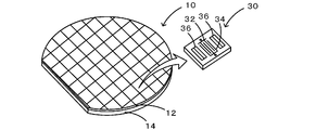
- FIG. 3 shows an example of an electronic device 30 manufactured using the composite substrate 10.
- the electronic device 30 is a 1-port SAW resonator, that is, a surface acoustic wave device.
- a pattern of a large number of electronic devices 30 is formed on the piezoelectric substrate 12 of the composite substrate 10 using a general photolithography technique, and then cut into individual electronic devices 30 by dicing.
- the electronic device 30 is obtained by forming IDT (Interdigital Transducer) electrodes 32 and 34 and a reflective electrode 36 on the surface of the piezoelectric substrate 12 by a photolithography technique.
- IDT Interdigital Transducer
- a mullite sintered body is also promising. Since the mullite sintered body has higher strength and higher Young's modulus than the cordierite sintered body and silicon, there is an advantage that the mullite sintered body is hard to be warped and cracked. Moreover, since the mullite sintered body has a thermal expansion coefficient close to that of silicon and GaN, it can be applied to existing silicon and GaN processes, and also has an insulating property. It can be applied as a support substrate for the used device.
- the mullite sintered body may have a mirror-polished surface, and the surface has a center line average roughness Ra of 1 nm or less in a measurement range of 10 ⁇ m square, or a measurement of 70 ⁇ m square.
- the maximum peak height Rp in the range is preferably 30 nm or less, or the number of pores having a maximum length of 0.1 ⁇ m or more in an arbitrary 4 ⁇ m ⁇ 4 ⁇ m range is preferably 10 or less.
- the mullite sintered body is preferably sintered by hot pressing.
- the mullite sintered body may contain at least one of cordierite, alumina, silica, spinel, and saphirin as a subphase.
- Such a mullite sintered support substrate and a functional substrate may be joined to produce a composite substrate. In that case, the ratio of the thicknesses of both substrates (the thickness of the functional substrate / the thickness of the support substrate) is: It is preferable that it is 0.1 or less.
- cordierite raw powders A to I For the production of the cordierite raw material powders A to H, commercially available magnesia, alumina, and silica powders having an average particle diameter of 1 ⁇ m or less and a purity of 99.9% or more were used. For comparison, in the raw material powder I, kaolin and talc, which are natural raw materials, were used as a part of the alumina, magnesia, and silica sources.
- cordierite raw material powder A Each powder of magnesia, alumina, and silica was weighed so as to have a cordierite composition, and heated at 1400 ° C. for 5 hours in an air atmosphere to obtain a cordierite coarse product.
- the resulting cordierite coarse particles are crushed for 70 hours in a pot mill using alumina cobblestone ( ⁇ 3 mm) and ion-exchanged water as a solvent, and pulverized cordierite having an average particle size of about 0.5 to 0.6 ⁇ m.
- a product was made.
- composition of this pulverized product was analyzed by the method described later, and the alumina content mixed in the pulverization process was readjusted to obtain a cordierite composition by appropriately adding magnesia and silica powder, and mixed again for 4 hours.
- the obtained slurry was dried at 110 ° C. under a nitrogen gas flow, and the dried product was passed through a sieve to obtain cordierite raw material powder A.
- -Cordierite raw material powder D It was produced by the same method as the cordierite raw material powder A, except that magnesia and silica were not added after pulverization.
- -Cordierite raw powder EH It was produced by the same method as the cordierite raw material powder A except that the adjustment of magnesia and silica was excessive or insufficient after pulverization.
- -Cordierite raw material powder I It was produced in the same manner as the cordierite raw material powder A except that kaolin and talc, which are natural raw materials, were used as a part of the alumina, magnesia and silica sources.
- Table 1 shows the final composition, the amount of impurity components, and the average particle size of the prepared cordierite raw material powders A to I.
- cordierite raw material powders A to I produced as described above is subjected to uniaxial die press molding at 50 kgf / cm 2 , and a molded body having a diameter of 100 mm and a thickness of about 25 mm.
- the obtained molded body is accommodated in a graphite mold and fired at a maximum temperature of 1400 to 1425 ° C. for 5 hours under a pressing pressure of 20 to 200 kgf / cm 2 using a hot press furnace to obtain a cordierite sintered body.
- the firing atmosphere was an argon atmosphere, the rate of temperature increase was 200 ° C./hr, the rate of temperature decrease was 200 ° C./hr, and the temperature was 1200 ° C. or lower during furnace cooling.
- an anti-folding rod, a disk-shaped sample of ⁇ 100 mm ⁇ thickness 1 mm, and the like were cut out and subjected to an evaluation test.
- the evaluation test is as follows.
- composition analysis The amount of MgO, Al 2 O 3 , SiO 2 , and impurity components in the cordierite raw material powder and the pulverized cordierite sintered body were measured by high-frequency inductively coupled plasma atomic emission spectrometry.
- Crystalline cordierite sintered body was pulverized, and cordierite and heterogeneous phases were identified and the peak top strength of each phase was calculated using an X-ray diffractometer.
- adopted when the 1st peak (strongest line) overlapped. Ix (Ip + Iq + Ir%) / Ic
- the total transmittance and linear transmittance for light having a wavelength of 200 to 3000 nm were measured on a cordierite sintered specimen having a thickness of 0.5 mm.
- a spectrophotometer was used for the measurement, and light transmitted through the sample was measured by injecting a nearly parallel light bundle from the normal direction of the sample surface.
- the standard sample is an air layer when the sample is not inserted into the optical path, the spectral transmittance is 1, and the transmitted light of the sample is received by the integrating sphere, so that the total transmittance is transmitted in the normal direction of the sample surface.
- the linear transmittance was calculated from the light.
- the total transmittance and linear transmittance for a wavelength of 550 nm were used as representative values.
- Table 2 shows the sintered body preparation conditions of each experimental example and the composition of the obtained cordierite sintered body
- Table 3 shows the results of the evaluation test of each experimental example, that is, the characteristics of the cordierite sintered body. Show. Experimental Examples 1 to 3, 12 to 17 correspond to examples of the present invention, and Experimental Examples 4 to 11 correspond to comparative examples of the present invention. The present invention is not limited to these experimental examples.
- the cordierite sintered body of Experimental Example 1 is obtained by sintering cordierite raw material powder A at 1425 ° C. for 5 hours under a press pressure of 200 kgf / cm 2 .
- the obtained cordierite sintered body has MgO / Al 2 O 3 and SiO 2 / Al 2 O 3 molar ratios of 1.00 and 2.50, respectively, and the deviation from the cordierite stoichiometric ratio is very large. It was small and the amount of impurities was small.
- the bulk density of the sintered body is 2.507g / cm 3, very close to 2.505g / cm 3 of cordierite true density, it was found that the closed pores are hardly contained.
- FIG. 1 The cordierite sintered body of Experimental Example 1 is obtained by sintering cordierite raw material powder A at 1425 ° C. for 5 hours under a press pressure of 200 kgf / cm 2 .
- the obtained cordierite sintered body has MgO / Al 2 O 3 and SiO 2
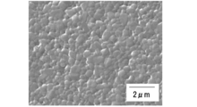
- FIG. 5 shows the result of thermal etching of the polished surface of the cordierite sintered body and SEM observation. From this, the average particle diameter of the cordierite sintered particles was 0.6 ⁇ m, and it was found that very fine cordierite particles were densely sintered. Further, in the 4 ⁇ m ⁇ 4 ⁇ m range of the polished surface, the number of pores having a maximum length of 0.1 ⁇ m or more was 3.
- the surface flatness of the polished surface was found to be as small as a center line average roughness Ra of 0.8 nm and a maximum peak height of 20 nm.
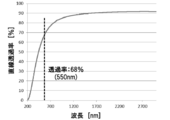
- FIG. 6 shows a transmittance curve as an optical characteristic. The linear transmittance was extremely high at 60% or more at 500 to 3000 nm, and it was found that the material had a very high transparency.
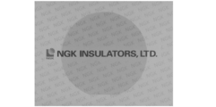
- An appearance photograph of the sample of the obtained cordierite sintered body is shown in FIG.
- the mark with the NGK logo drawn in FIG. 7 is a registered trademark of Nippon Kyoko Co., Ltd.
- Example 4 In Experimental Example 4, a cordierite sintered body was produced under the same conditions as in Experimental Example 1 except that the firing temperature was 1400 ° C. Since the firing temperature was low, the cordierite-forming reaction of the raw material components such as alumina and silica did not proceed sufficiently, and it was found that many different phases of corundum and cristobalite remained.
- the surface flatness of the polished surface was as high as 1.8 nm for the center line average roughness Ra and 28 nm for the maximum peak height Rp. From these, it is presumed that the ease of polishing differs between cordierite and the different phase component, and it tends to remain in a convex shape because the different phase component is particularly difficult to polish.
- Example 5 In Experimental Example 5, a cordierite sintered body was produced under the same conditions as in Experimental Example 2 except that the firing temperature was 1400 ° C. Similar to Experimental Example 4, since the firing temperature was low, corundum and cristobalite remained as different phases, and the surface flatness of the polished surface was not good when Ra was 1.3 nm and Rp was 31 nm.
- Example 6 a cordierite sintered body was produced under the same conditions as in Experimental Example 1 except that the cordierite raw material powder D was used. Since the alumina in the raw material is excessive, the sintered body also has an excess of alumina, the molar ratio of MgO / Al 2 O 3 is 0.94, and the molar ratio of SiO 2 / Al 2 O 3 is 2.36. It was smaller than the composition. The amount of corundum and cristobalite detected as a different phase was large, and the surface flatness of the polished surface was large when Ra was 3.5 nm and Rp was 88 nm, and it was impossible to finish with high flatness.
- Example 7 In Experimental Example 7, a cordierite sintered body was produced under the same conditions as in Experimental Example 1 except that the cordierite raw material powder E was used.
- the cordierite sintered body had a MgO / Al 2 O 3 molar ratio of 0.93, which was insufficient for MgO, corundum and cristobalite were detected as heterogeneous phases, and the peak intensity ratio Ix was found to be large. Therefore, the surface flatness of the polished surface was large when Ra was 3.3 nm and Rp was 67 nm, and it was impossible to finish with high flatness.
- Example 8 In Experimental Example 8, a cordierite sintered body was produced under the same conditions as in Experimental Example 1 except that the cordierite raw material powder F was used.
- the cordierite sintered body had a SiO 2 / Al 2 O 3 molar ratio of 2.42 and a lack of SiO 2 , corundum was detected as a heterogeneous phase, and the peak intensity ratio Ix was found to be large. Therefore, the surface flatness of the polished surface was large when Ra was 2.1 nm and Rp was 40 nm, and it was impossible to finish with high flatness.
- Example 9 a cordierite sintered body was produced under the same conditions as in Experimental Example 1 except that the cordierite raw material powder G was used.
- the cordierite sintered body has a MgO / Al 2 O 3 molar ratio of 1.09 and an excessive amount of MgO, XRD detected enstatite as a heterogeneous phase, and small amounts of corundum and cristobalite were also observed. .
- the peak intensity ratio Ix by XRD was high, and the amount of different phases was large. For this reason, the surface flatness of the polished surface was as high as 1.5 nm for Ra and 29 nm for Rp, and could not be finished with high flatness.
- FIG. 8 shows an XRD diffractogram of the ground cordierite sintered body of Experimental Example 10. From FIG. 8, it was found from XRD that cristobalite and a small amount of corundum were detected as different phases, and the amount of different phases was larger than the peak intensity ratio Ix. Therefore, the surface flatness of the polished surface was large when Ra was 3.1 nm and Rp was 47 nm, and it was impossible to finish with high flatness.
- Example 11 In Experimental Example 11, a cordierite raw material powder I was used, and a cordierite sintered body was produced under the same conditions as in Experimental Example 1 except that the firing temperature was 1400 ° C. Many Fe 2 O 3 and TiO 2 components, which are impurities derived from natural raw materials, were contained. From XRD, iron oxide, corundum, and saphirin were detected as different phases, the peak intensity ratio Ix was high, and the amount of different phases was large. For this reason, the surface flatness of the polished surface was 3.5 nm for Ra and 84 nm for Rp, and could not be finished with high flatness.
- LT lithium tantalate
- LN lithium niobate
- GaN gallium nitride
- Si silicon
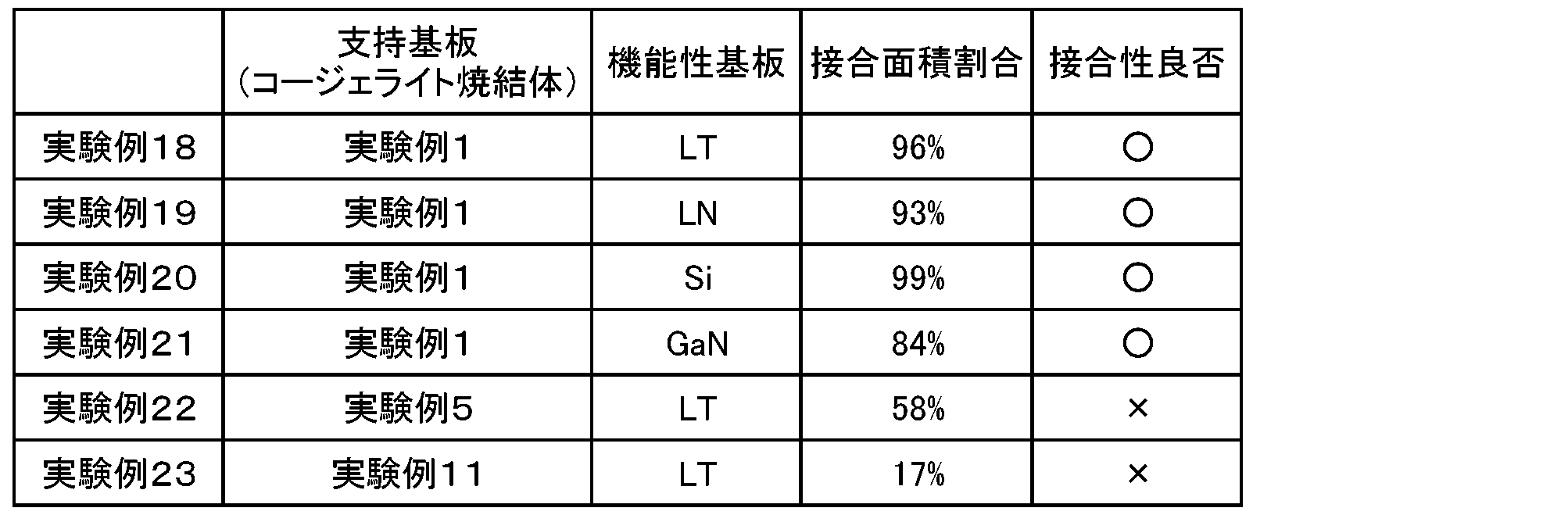
- Experimental Example 19 an LN substrate was used instead of the LT substrate, and direct bonding with a support substrate having a thickness of 500 ⁇ m was attempted in the same manner as in Experimental Example 18.
- the joining area ratio was 90% or more, and it was satisfactorily joined as in Experimental Example 18.
- Example 22 a composite substrate was produced using the cordierite sintered body of Experimental Example 5 as a support substrate.
- This support substrate was directly bonded to the LT substrate in the same manner as in Experimental Example 18. However, the bonding area ratio did not reach 60%, voids were seen at the interface, and sufficient bonding could not be obtained. It was.
- a composite substrate was produced using the cordierite sintered body of Experimental Example 11 as a support substrate.
- This support substrate (thickness: 230 ⁇ m) was directly bonded to the LT substrate in the same manner as in Experimental Example 18, but the bonding area ratio was 20% or less, and sufficient bonding was not obtained.
- Table 4 summarizes the materials used in Experimental Examples 18 to 23, the bonding area ratio, and the bonding quality.
- a porous sintered structure can be used as a catalyst carrier or filter for exhaust gas purification of automobiles and the like.
Landscapes
- Chemical & Material Sciences (AREA)
- Engineering & Computer Science (AREA)
- Ceramic Engineering (AREA)
- Materials Engineering (AREA)
- Organic Chemistry (AREA)
- Manufacturing & Machinery (AREA)
- Structural Engineering (AREA)
- Inorganic Chemistry (AREA)
- Crystallography & Structural Chemistry (AREA)
- Metallurgy (AREA)
- Compositions Of Oxide Ceramics (AREA)
- Ceramic Products (AREA)
Abstract
Description
MgO成分、Al2O3成分、SiO2成分が所定の割合で配合された混合粉末を焼成してコージェライト粗粒物にする(図1のS1)。ここで、混合粉末とは、焼成によりコージェライトとなる3成分を混合した粉末を意味し、例えばMgO成分が13.8質量%、Al2O3成分が34.9質量%、SiO2成分が51.3質量%となるように配合された混合粉末であることが好ましい。ないしは、予め粉砕工程で混入する成分の量が想定できる場合、例えば粉砕工程で使用するアルミナメディア(アルミナボールやアルミナポットなど)からのアルミナ成分の混入量が想定できる場合、混合粉末に配合するAl2O3成分の量を少なくしておいてもよい。更に本発明のコージェライト焼結体では、不純物成分が異相を形成するのを避けることが重要であるため、できるだけ高純度な原料を使用することが好ましく、混合粉末に配合する各成分の純度は99.9%以上であることが好ましい。但し、加熱により飛散する成分、例えばCO2、H2O等は不純物には含めていない。
得られたコージェライト原料粉末を所定形状に成形する(図1のS4)。成形の方法に特に制限はなく、一般的な成形法を用いることができる。例えば、上記のようなコージェライト原料粉末をそのまま金型によってプレス成形してもよい。プレス成形の場合は、コージェライト原料粉末をスプレードライによって顆粒状にしておくと、成形性が良好になる。他に、有機バインダーを加えて坏土を作製し押出し成形したり、スラリーを作製しシート成形することができる。これらのプロセスでは焼成工程前あるいは焼成工程中に有機バインダー成分を除去することが必要になる。また、CIP(冷間静水圧プレス)にて高圧成形をしてもよい。
(原料粉末A~I)
コージェライト原料粉末A~Hの作製には、市販の平均粒径1μm以下、純度99.9%以上の高純度なマグネシア、アルミナ、シリカ粉末を用いた。また、比較として、原料粉末Iでは、天然原料であるカオリン、タルクをアルミナ、マグネシア、シリカ源の一部に用いた。
マグネシア、アルミナ、シリカの各粉末を、コージェライト組成になるように秤量し、1400℃で5時間大気雰囲気下で加熱し、コージェライト粗粒物を得た。得られたコージェライト粗粒物に対し、アルミナを玉石(φ3mm)とし、溶媒にイオン交換水を用いたポットミルにて70時間粉砕し、平均粒径0.5~0.6μm程度のコージェライト粉砕物を作製した。この粉砕物を後述する方法にて組成分析し、粉砕過程で混入したアルミナ分に対し、マグネシア、シリカ粉末を適宜追加することでコージェライト組成になるように再調整し、再度4時間混合した。得られたスラリーを窒素ガスフロー下、110℃で乾燥をし、乾燥物を篩に通してコージェライト原料粉末Aとした。
粉砕工程におけるアルミナメディアからのアルミナ混入量分を、予めコージェライト組成から減量した組成となるように、マグネシア、アルミナ、シリカの各粉末を秤量し、粉砕後にマグネシア、シリカ粉末の追加を行わなかった以外は、コージェライト原料粉末Aと同様の方法で作製した。
粉砕後にマグネシア、シリカの追加を行わなかった以外は、コージェライト原料粉末Aと同様の方法で作製した。
・コージェライト原料粉末E~H
粉砕後にマグネシア、シリカの調整を過剰または過少とした以外は、コージェライト原料粉末Aと同様な方法で作製した。
アルミナ、マグネシア、シリカ源の一部に天然原料であるカオリン、タルクを用いた他はコージェライト原料粉末Aと同様の方法で作製した。

上記のようにして作製したコージェライト原料粉末A~Iのそれぞれを、50kgf/cm2にて一軸金型プレス成形をし、φ100mmで厚さ25mm程度の成形体を得た。得られた成形体を黒鉛製のモールドに収容し、ホットプレス炉を用いて、プレス圧力20~200kgf/cm2下で最高温度1400~1425℃で5時間焼成をし、コージェライト焼結体を作製した。焼成雰囲気はアルゴン雰囲気とし、昇温速度は200℃/hr、降温速度は200℃/hrとし、降温時は1200℃以下を炉冷とした。得られた各コージェライト焼結体から、抗折棒、及び、φ100mm×厚さ1mmの円盤状の試料等を切り出し、評価試験に供した。評価試験は以下のとおり。
高周波誘導結合プラズマ発光分光分析法により、コージェライト原料粉末、コージェライト焼結体の粉砕物のMgO、Al2O3、SiO2、不純物成分の量を測定した。
抗折棒を用い、純水を用いたアルキメデス法により、嵩密度を測定した。
コージェライト焼結体を粉砕し、X線回折装置により、コージェライト、異相の同定と各相のピークトップ強度の算出を行った。測定条件はCuKα、50kV、300mA、2θ=5-70°とし、回転対陰極型X線回折装置「理学電機製「RINT」を用いた。X線回折図から、コージェライトの(110)面のピークトップ強度(Ic)に対する、検出された各異相(P、Q、R、・・・)の最大ピークの強度(Ip、Iq、Ir、・・・)の総和の比(Ix)を求めた。なお、第一ピーク(最強線)が重なる場合は第二ピークを採用した。
Ix=(Ip+Iq+Ir・・・)/Ic
4×3×10mmのコージェライト焼結体の試験片に対し、一面を研磨によって鏡面状に仕上げた。鏡面状に仕上げた表面に対し、AFMを用いて中心性平均粗さRaと、最大山高さRpを測定した。それぞれの測定範囲は、10μm×10μm、70μm×70μmとした。なお、研磨は、3μmのダイヤモンド砥粒、0.5μmのダイヤモンド砥粒の順に進め、最終仕上げにはコロイダルシリカスラリー(pH=11、粒径80nm)と不織布パッドを用いたバフ研磨とした。
上記のように仕上げた焼結体の研磨面を、1400℃で2hrサーマルエッチングをし、SEMにてコージェライト焼結粒子の大きさを平均粒径として算出した。算出には線分法を用い、測定値に対して1.5倍した値を平均粒径とした。
上記のように仕上げた焼結体の研磨面に対し、任意の4μm×4μm範囲をAFM観察し、最大長さが0.1μm以上の気孔の数を測定した。
厚さ0.5mmのコージェライト焼結体の試験片に対し、波長200~3000nmの光に対する全透光率、直線透過率を測定した。測定には分光光度計を用い、試料面の法線方向から平行に近い光線束を入射させて試料の透過光を測定した。標準試料は、光路中に試料を挿入しない場合の空気層とし、その分光透過率を1として、試料の透過光を積分球で受けることで全透光率を、試料面の法線方向の透過光から直線透過率をそれぞれ算出した。550nmの波長に対する全透光率、直線透過率を代表値とした。

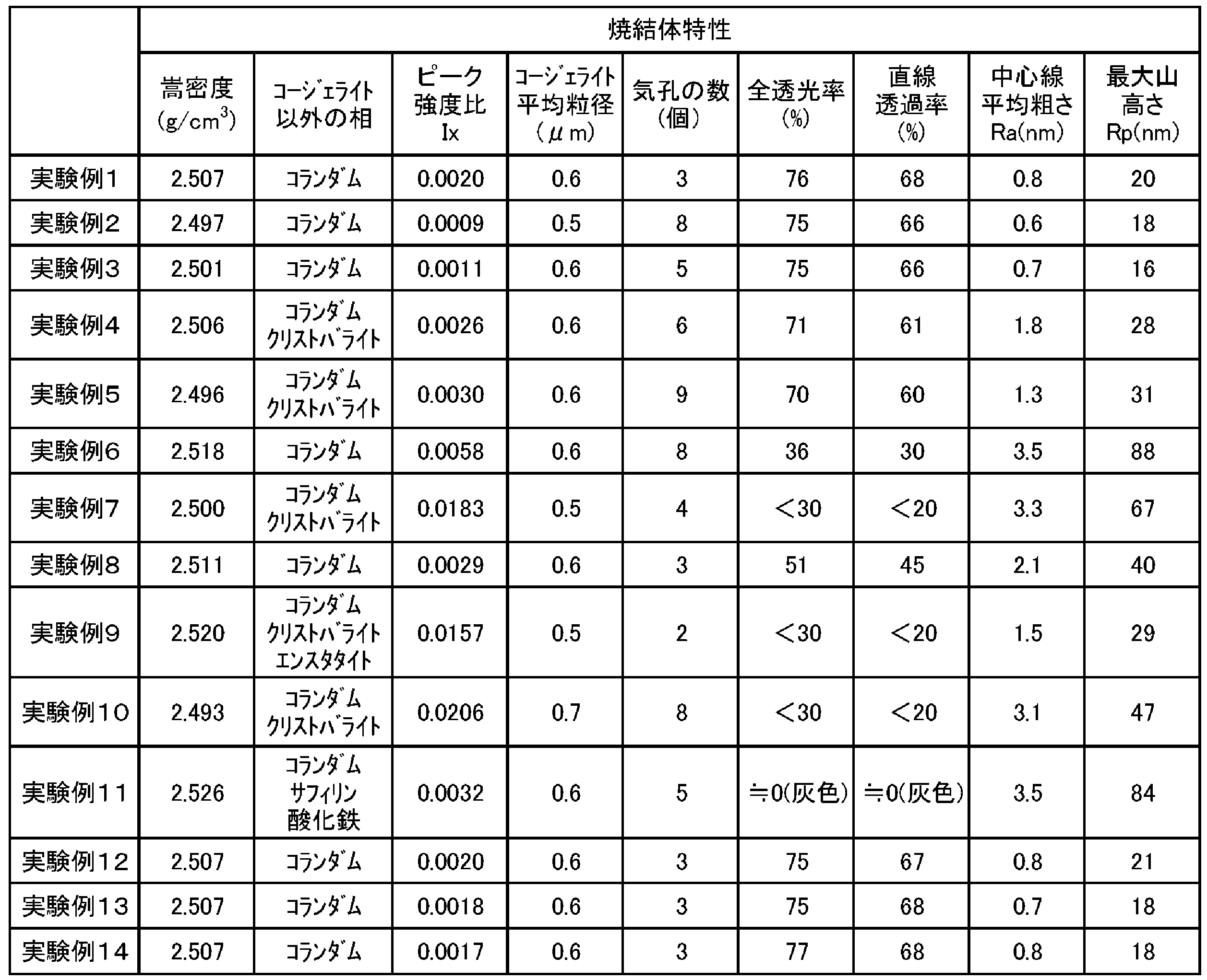
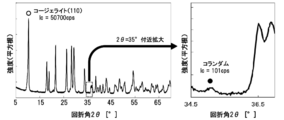
実験例1のコージェライト焼結体は、コージェライト原料粉末Aを、プレス圧力200kgf/cm2下で1425℃で5hr焼結したものである。得られたコージェライト焼結体のMgO/Al2O3、SiO2/Al2O3のモル比はそれぞれ1.00、2.50であり、コージェライトの量論比からのずれは非常に小さく、不純物量も少なかった。焼結体の嵩密度は2.507g/cm3であり、コージェライト真密度の2.505g/cm3に極めて近く、閉気孔が殆ど含まれないことがわかった。図4に、実験例1のコージェライト焼結体粉砕物のXRD回折図を示す。コージェライト以外の相としてコランダム(図中●)のみが検出されたが、コージェライト(110)(図中○)のピークトップ強度に対するピーク強度比Ixは0.0020であり、極めて小さかった。図5に、コージェライト焼結体の研磨面をサーマルエッチングし、SEM観察した結果を示す。これより、コージェライト焼結粒子の平均粒径は0.6μmであり、非常に微細なコージェライト粒子が緻密に焼結していることがわかった。また、研磨面の4μm×4μm範囲において、最大長さが0.1μm以上の気孔の数は3個であった。研磨面の表面平坦性は、中心線平均粗さRaが0.8nmで小さく、最大山高さも20nmで小さいことがわかった。図6には光学特性として透過率曲線を示す。直線透過率は500~3000nmで60%以上で極めて高く、非常に透明性の高い材料であることがわかった。得られたコージェライト焼結体のサンプルの外観写真を図7に示した。図7に描かれたNGKのロゴ入りマークは日本碍子(株)の登録商標である。
実験例2,3のコージェライト焼結体は、コージェライト原料粉末B,Cをそれぞれ、実験例1と同様な条件で焼結したものである。得られたコージェライト焼結体の組成、成分のモル比は表2の通りであり、いずれもコージェライトの量論比からのずれは非常に小さかった。他の特性においても、実験例1と類似の特性が得られており、異相が少ない状態で緻密性が高く気孔が少なく焼結できており、表面平坦性の高い材料ができていることがわかった。透明性も実験例1と同様に高かった。
実験例4では、焼成温度を1400℃とした以外は、実験例1と同様な条件でコージェライト焼結体を作製した。焼成温度が低いため、アルミナやシリカ等原料成分のコージェライト化反応が十分進まず、コランダムやクリストバライトの異相が多く残っていることがわかった。研磨面の表面平坦性は、中心線平均粗さRaが1.8nm、最大山高さRpが28nmと大きかった。これらより、コージェライトと異相成分との間で研磨のされ易さが異なり、特に異相成分が研磨され難いことによって凸状に残り易いと推定される。
実験例5では、焼成温度を1400℃とした以外は、実験例2と同様な条件でコージェライト焼結体を作製した。実験例4と同様、焼成温度が低いため、コランダムとクリストバライトが異相として残り、研磨面の表面平坦性は、Raが1.3nm、Rpが31nmで共に良くなかった。
実験例6では、コージェライト原料粉末Dを用いた以外は、実験例1と同様な条件でコージェライト焼結体を作製した。原料中のアルミナが過剰であるため、焼結体でもアルミナ過剰となり、MgO/Al2O3のモル比が0.94、SiO2/Al2O3のモル比が2.36で、コージェライト組成よりも小さかった。異相として検出されるコランダムやクリストバライトの量が多く、研磨面の表面平坦性は、Raが3.5nm、Rpが88nmで大きく、平坦性高く仕上げることができなかった。
実験例7では、コージェライト原料粉末Eを用いた以外は、実験例1と同様な条件でコージェライト焼結体を作製した。コージェライト焼結体のMgO/Al2O3のモル比が0.93とMgOが不足しており、コランダムやクリストバライトが異相として検出され、ピーク強度比Ixからその量も多いことがわかった。そのため研磨面の表面平坦性は、Raが3.3nm、Rpが67nmで大きく、平坦性高く仕上げることができなかった。
実験例8では、コージェライト原料粉末Fを用いた以外は、実験例1と同様な条件でコージェライト焼結体を作製した。コージェライト焼結体のSiO2/Al2O3のモル比が2.42とSiO2が不足しており、コランダムが異相として検出され、ピーク強度比Ixからその量も多いことがわかった。そのため研磨面の表面平坦性は、Raが2.1nm、Rpが40nmで大きく、平坦性高く仕上げることができなかった。
実験例9では、コージェライト原料粉末Gを用いた以外は、実験例1と同様な条件でコージェライト焼結体を作製した。コージェライト焼結体のMgO/Al2O3のモル比が1.09とMgOが過剰に存在しており、XRDからエンスタタイトが異相として検出され、他に少量のコランダム、クリストバライトが認められた。XRDでのピーク強度比Ixは高く、異相量は多かった。そのため研磨面の表面平坦性は、Raが1.5nm、Rpが29nmで大きく、平坦性高く仕上げることができなかった。
実験例10では、コージェライト原料粉末Hを用いた以外は、実験例1と同様な条件でコージェライト焼結体を作製した。コージェライト焼結体のSiO2/Al2O3のモル比が2.65であり、SiO2が過剰に存在していた。図8に実験例10のコージェライト焼結体の粉砕物のXRD回折図を示す。図8から、XRDからクリストバライトと少量のコランダムが異相として検出され、ピーク強度比Ixより異相量が多いことがわかった。そのため研磨面の表面平坦性は、Raが3.1nm、Rpが47nmで大きく、平坦性高く仕上げることができなかった。
実験例11では、コージェライト原料粉末Iを用い、焼成温度を1400℃とした以外は、実験例1と同様な条件でコージェライト焼結体を作製した。天然原料由来の不純物であるFe2O3やTiO2成分が多く含まれていた。XRDから、酸化鉄、コランダム、サフィリンが異相として検出され、ピーク強度比Ixは高く、異相量は多かった。そのため研磨面の表面平坦性は、Raが3.5nm、Rpが84nmとなり、平坦性高く仕上げることができなかった。
実験例12,13,14では、プレス圧力をそれぞれ20,50,100kgf/cm2とした以外は、実験例1と同様な条件でコージェライト焼結体を作製した。得られたコージェライト焼結体の組成、成分のモル比は表2の通りであり、いずれもコージェライトの量論比からのずれは非常に小さかった。また、他の特性は、表3の通りであり、実験例1と類似の特性が得られており、異相が少ない状態で緻密性が高く気孔が少なく焼結できており、表面平坦性の高い材料ができていることがわかった。透明性も実験例1と同様の高かった。低いプレス圧力でコージェライト焼結体を作製できるため、ホットプレス治具を小型化、長寿命化することができる。
実験例15,16,17では、実験例1のコージェライト焼結体をそれぞれ1200℃、1300℃、1400℃で2時間アニール処理を行い、光学特性を評価した。全透光率がそれぞれ80%、83%、84%、直線透過率がそれぞれ70%、70%、71%となり、高温でアニール処理することで透光性、透明性の向上が見られた。
コージェライト焼結体を支持基板として用いて複合基板を作製した。具体的な作製例を実験例18~23に示す。なお、実験例18~21が本発明の実施例に相当し、実験例22,23が本発明の比較例に相当する。
実験例18~21は、実験例1のコージェライト焼結体を支持基板として用いて、複合基板を作製した。支持基板は、φ100mm×厚さ230μm又は500μmの形状とし、表面をダイヤラップ研磨及びCMP研磨により、Ra=0.4~0.9nm、Rp=6~20nmに仕上げたものを使用した。CMP研磨後の支持基板は、一般的に用いられるアミン溶液、SPM(硫酸加水)とRCA洗浄液を用いた洗浄処理をし、基板表面の有機物やパーティクル等の除去を行い、接合に供した。一方、機能性基板にはタンタル酸リチウム(LT)、ニオブ酸リチウム(LN)、窒化ガリウム(GaN)、シリコン(Si)のいずれも単結晶基板を用い、形状、表面仕上げ共に支持基板と同様にしたものを使用した。
実験例22では、実験例5のコージェライト焼結体を支持基板として用いて、複合基板を作製した。支持基板の厚さは230μm、表面はRa=1.4nm、Rp=35nmに仕上げたものを使用した。この支持基板に対して、実験例18と同様にしてLT基板との直接接合を試みたが、接合面積割合は60%に届かず、界面には空隙が見られ、十分な接合が得られなかった。
Claims (15)
- X線回折図において、コージェライトの(110)面のピークトップ強度に対する、コージェライト成分以外の各成分の最大ピークの強度の総和の比が、0.0025以下である、コージェライト焼結体。
- MgO/Al2O3のモル比が0.96~1.04、SiO2/Al2O3のモル比が2.46~2.54である、請求項1に記載のコージェライト焼結体。
- MgO,Al2O3及びSiO2の3成分が全体に占める割合が99.9質量%以上である、請求項1又は2に記載のコージェライト焼結体。
- コージェライト焼結粒子の平均粒径が1μm以下である、請求項1~3のいずれか1項に記載のコージェライト焼結体。
- 波長550nmの光に対する全透光率が60%以上である、請求項1~4のいずれか1項に記載のコージェライト焼結体。
- 波長550nmの光に対する直線透過率が50%以上である、請求項1~5のいずれか1項に記載のコージェライト焼結体。
- 鏡面状に研磨仕上げした表面を有する、請求項1~6のいずれか1項に記載のコージェライト焼結体。
- 前記表面は、10μm四方の測定範囲における中心線平均粗さRaが1nm以下である、請求項7に記載のコージェライト焼結体。
- 前記表面は、70μm四方の測定範囲における最大山高さRpが30nm以下である、請求項7又は8に記載のコージェライト焼結体。
- MgO成分、Al2O3成分及びSiO2成分を含むコージェライト原料粉末を不活性雰囲気下、ホットプレス法で焼結することによりコージェライト焼結体を製造する方法であって、
前記コージェライト原料粉末は、MgO/Al2O3のモル比が0.96~1.04、SiO2/Al2O3のモル比が2.46~2.54、MgO、SiO2及びAl2O3の3成分が全体に占める割合が99.9質量%以上、平均粒径D50が1μm以下であり、
前記ホットプレス法で焼結する際の条件は、プレス圧力が20~300kgf/cm2、焼成温度が1410~1450℃である、
コージェライト焼結体の製法。 - 前記コージェライト焼結体は、請求項1~9のいずれか1項に記載のコージェライト焼結体である、
請求項10に記載のコージェライト焼結体の製法。 - 機能性基板と、コージェライト焼結体製の支持基板とが接合された複合基板であって、接合界面のうち実際に接合している面積の割合(接合面積割合)が80%以上である複合基板。
- 前記コージェライト焼結体は、請求項7~9のいずれか1項に記載のコージェライト焼結体である、請求項12に記載の複合基板。
- 前記接合が直接接合である、請求項12又は13に記載の複合基板。
- 請求項12~14のいずれか1項に記載の複合基板を利用した電子デバイス。
Priority Applications (6)
| Application Number | Priority Date | Filing Date | Title |
|---|---|---|---|
| JP2015550108A JP5890945B1 (ja) | 2014-06-06 | 2015-05-26 | コージェライト焼結体、その製法、複合基板及び電子デバイス |
| DE112015000214.6T DE112015000214B4 (de) | 2014-06-06 | 2015-05-26 | Gesinterter Cordieritkörper, Verfahren für dessen Herstellung und dessen Verwendung |
| KR1020167013577A KR101687145B1 (ko) | 2014-06-06 | 2015-05-26 | 코디어라이트 소결체, 그 제법, 복합 기판 및 전자 디바이스 |
| CN201580002729.5A CN105764871A (zh) | 2014-06-06 | 2015-05-26 | 堇青石烧结体、其制法、复合基板以及电子器件 |
| CN202110301472.0A CN112851320B (zh) | 2014-06-06 | 2015-05-26 | 堇青石烧结体、其制法、复合基板以及电子器件 |
| US15/160,224 US9771303B2 (en) | 2014-06-06 | 2016-05-20 | Cordierite sintered body, method for manufacturing the same, composite substrate, and electronic device |
Applications Claiming Priority (4)
| Application Number | Priority Date | Filing Date | Title |
|---|---|---|---|
| JP2014-117926 | 2014-06-06 | ||
| JP2014117926 | 2014-06-06 | ||
| JP2015-059873 | 2015-03-23 | ||
| JP2015059873 | 2015-03-23 |
Related Child Applications (1)
| Application Number | Title | Priority Date | Filing Date |
|---|---|---|---|
| US15/160,224 Continuation US9771303B2 (en) | 2014-06-06 | 2016-05-20 | Cordierite sintered body, method for manufacturing the same, composite substrate, and electronic device |
Publications (1)
| Publication Number | Publication Date |
|---|---|
| WO2015186571A1 true WO2015186571A1 (ja) | 2015-12-10 |
Family
ID=54766644
Family Applications (1)
| Application Number | Title | Priority Date | Filing Date |
|---|---|---|---|
| PCT/JP2015/065096 Ceased WO2015186571A1 (ja) | 2014-06-06 | 2015-05-26 | コージェライト焼結体、その製法、複合基板及び電子デバイス |
Country Status (7)
| Country | Link |
|---|---|
| US (1) | US9771303B2 (ja) |
| JP (1) | JP5890945B1 (ja) |
| KR (1) | KR101687145B1 (ja) |
| CN (2) | CN105764871A (ja) |
| DE (1) | DE112015000214B4 (ja) |
| TW (1) | TW201609601A (ja) |
| WO (1) | WO2015186571A1 (ja) |
Cited By (5)
| Publication number | Priority date | Publication date | Assignee | Title |
|---|---|---|---|---|
| DE102017002735A1 (de) | 2016-03-23 | 2017-09-28 | Ngk Insulators, Ltd. | Cordierit-basierter Sinterkörper, Verfahren zur Herstellung desselben und Verbund- werkstoffsubstrat |
| JP2017178773A (ja) * | 2016-03-23 | 2017-10-05 | 日本碍子株式会社 | コージェライト質焼結体、その製法及び複合基板 |
| JP2020150488A (ja) * | 2019-03-15 | 2020-09-17 | 日本電気硝子株式会社 | 複合基板、電子デバイス、複合基板の製造方法及び電子デバイスの製造方法 |
| US20240258983A1 (en) * | 2023-01-30 | 2024-08-01 | Sanan Japan Technology Corporation | Acoustic wave device and method for producing same |
| WO2024202584A1 (ja) * | 2023-03-31 | 2024-10-03 | 住友化学株式会社 | 複合酸化物粒子 |
Families Citing this family (6)
| Publication number | Priority date | Publication date | Assignee | Title |
|---|---|---|---|---|
| CN108424133B (zh) * | 2018-04-16 | 2021-03-26 | 河南工业大学 | 一种堇青石/氮化铝电子封装陶瓷基片及制备方法 |
| WO2020066914A1 (ja) | 2018-09-26 | 2020-04-02 | 京セラ株式会社 | コーディエライト質セラミックスおよび望遠鏡用部材 |
| WO2021154713A1 (en) * | 2020-01-27 | 2021-08-05 | Heraeus Conamic North America Llc | High purity cordierite material for semiconductor applications |
| GB2596823B (en) * | 2020-07-07 | 2022-08-24 | Ceramic Additive Mfg Ltd | 3D ceramic printing |
| US11731907B2 (en) | 2020-08-04 | 2023-08-22 | Applied Materials, Inc. | Ceramic material with high thermal shock resistance and high erosion resistance |
| CN116848074A (zh) * | 2021-03-05 | 2023-10-03 | Agc株式会社 | 堇青石质烧结体及其制造方法 |
Citations (4)
| Publication number | Priority date | Publication date | Assignee | Title |
|---|---|---|---|---|
| JPH0426543A (ja) * | 1990-05-22 | 1992-01-29 | Agency Of Ind Science & Technol | 透光性コーディエライト焼結体及びその製造法 |
| JP2001110841A (ja) * | 1999-10-07 | 2001-04-20 | Kyocera Corp | ワイヤボンディング用キャピラリー |
| JP2008007341A (ja) * | 2006-06-27 | 2008-01-17 | Nippon Steel Materials Co Ltd | 低熱膨張セラミックス接合体及びその製造方法 |
| JP2012087026A (ja) * | 2010-10-21 | 2012-05-10 | Kurosaki Harima Corp | コーディエライト質焼結体 |
Family Cites Families (11)
| Publication number | Priority date | Publication date | Assignee | Title |
|---|---|---|---|---|
| JPS6389455A (ja) * | 1986-10-01 | 1988-04-20 | 東レ株式会社 | ムライト焼結体 |
| US5064790A (en) * | 1989-12-19 | 1991-11-12 | Uop | High density cordierite ceramics from zeolite |
| JP3880150B2 (ja) | 1997-06-02 | 2007-02-14 | 松下電器産業株式会社 | 弾性表面波素子 |
| JP4540025B2 (ja) * | 1998-12-07 | 2010-09-08 | コーニング インコーポレイテッド | 超低熱膨張コージエライト構造体の製造 |
| JP5011609B2 (ja) * | 2001-04-24 | 2012-08-29 | 日立化成工業株式会社 | 緻密コーディエライト質セラミックス及びその製造方法 |
| JP3774782B2 (ja) * | 2003-05-14 | 2006-05-17 | 富士通メディアデバイス株式会社 | 弾性表面波素子の製造方法 |
| JP2005314215A (ja) | 2004-03-29 | 2005-11-10 | Ngk Insulators Ltd | 緻密質コーディエライト焼結体及びその製造方法 |
| JP5657210B2 (ja) | 2009-01-28 | 2015-01-21 | 京セラ株式会社 | コージェライト質焼結体からなる半導体製造装置用部材 |
| KR101155070B1 (ko) | 2010-04-20 | 2012-06-11 | 비옥토자연순환농업센터 영농조합법인 | 가축분료를 이용한 액체비료의 제조방법 |
| JP6003617B2 (ja) | 2012-12-19 | 2016-10-05 | セイコーエプソン株式会社 | 印刷装置 |
| JP5865879B2 (ja) | 2013-09-19 | 2016-02-17 | エスペック株式会社 | 環境試験装置 |
-
2015
- 2015-05-26 JP JP2015550108A patent/JP5890945B1/ja active Active
- 2015-05-26 WO PCT/JP2015/065096 patent/WO2015186571A1/ja not_active Ceased
- 2015-05-26 KR KR1020167013577A patent/KR101687145B1/ko active Active
- 2015-05-26 DE DE112015000214.6T patent/DE112015000214B4/de active Active
- 2015-05-26 CN CN201580002729.5A patent/CN105764871A/zh active Pending
- 2015-05-26 CN CN202110301472.0A patent/CN112851320B/zh active Active
- 2015-05-28 TW TW104117123A patent/TW201609601A/zh unknown
-
2016
- 2016-05-20 US US15/160,224 patent/US9771303B2/en active Active
Patent Citations (4)
| Publication number | Priority date | Publication date | Assignee | Title |
|---|---|---|---|---|
| JPH0426543A (ja) * | 1990-05-22 | 1992-01-29 | Agency Of Ind Science & Technol | 透光性コーディエライト焼結体及びその製造法 |
| JP2001110841A (ja) * | 1999-10-07 | 2001-04-20 | Kyocera Corp | ワイヤボンディング用キャピラリー |
| JP2008007341A (ja) * | 2006-06-27 | 2008-01-17 | Nippon Steel Materials Co Ltd | 低熱膨張セラミックス接合体及びその製造方法 |
| JP2012087026A (ja) * | 2010-10-21 | 2012-05-10 | Kurosaki Harima Corp | コーディエライト質焼結体 |
Cited By (8)
| Publication number | Priority date | Publication date | Assignee | Title |
|---|---|---|---|---|
| DE102017002735A1 (de) | 2016-03-23 | 2017-09-28 | Ngk Insulators, Ltd. | Cordierit-basierter Sinterkörper, Verfahren zur Herstellung desselben und Verbund- werkstoffsubstrat |
| JP2017178773A (ja) * | 2016-03-23 | 2017-10-05 | 日本碍子株式会社 | コージェライト質焼結体、その製法及び複合基板 |
| US11198648B2 (en) | 2016-03-23 | 2021-12-14 | Ngk Insulators, Ltd. | Cordierite-based sintered body, method for producing the same, and composite substrate |
| DE102017002735B4 (de) | 2016-03-23 | 2022-06-15 | Ngk Insulators, Ltd. | Cordierit-basierter Sinterkörper, Verfahren zur Herstellung desselben und Verwendung |
| JP2020150488A (ja) * | 2019-03-15 | 2020-09-17 | 日本電気硝子株式会社 | 複合基板、電子デバイス、複合基板の製造方法及び電子デバイスの製造方法 |
| JP7279432B2 (ja) | 2019-03-15 | 2023-05-23 | 日本電気硝子株式会社 | 複合基板、電子デバイス、複合基板の製造方法及び電子デバイスの製造方法 |
| US20240258983A1 (en) * | 2023-01-30 | 2024-08-01 | Sanan Japan Technology Corporation | Acoustic wave device and method for producing same |
| WO2024202584A1 (ja) * | 2023-03-31 | 2024-10-03 | 住友化学株式会社 | 複合酸化物粒子 |
Also Published As
| Publication number | Publication date |
|---|---|
| JP5890945B1 (ja) | 2016-03-22 |
| TWI561491B (ja) | 2016-12-11 |
| CN112851320A (zh) | 2021-05-28 |
| CN112851320B (zh) | 2026-06-02 |
| CN105764871A (zh) | 2016-07-13 |
| TW201609601A (zh) | 2016-03-16 |
| DE112015000214T5 (de) | 2016-08-18 |
| US20160264471A1 (en) | 2016-09-15 |
| JPWO2015186571A1 (ja) | 2017-04-20 |
| KR20160067185A (ko) | 2016-06-13 |
| DE112015000214B4 (de) | 2019-01-03 |
| US9771303B2 (en) | 2017-09-26 |
| KR101687145B1 (ko) | 2016-12-15 |
Similar Documents
| Publication | Publication Date | Title |
|---|---|---|
| JP5890945B1 (ja) | コージェライト焼結体、その製法、複合基板及び電子デバイス | |
| CN105636920B (zh) | 莫来石烧结体、其制法以及复合基板 | |
| CN109690943B (zh) | 复合基板及其制法以及电子器件 | |
| KR102377658B1 (ko) | 코디어라이트질 소결체, 그 제법 및 복합 기판 | |
| CN107840664B (zh) | 硅铝氧氮陶瓷烧结体、其制法、复合基板及电子器件 | |
| JP6940959B2 (ja) | コージェライト質焼結体、その製法及び複合基板 | |
| KR102377657B1 (ko) | 멀라이트 함유 소결체, 그 제법 및 복합 기판 | |
| JP7018267B2 (ja) | サイアロン焼結体、その製法、複合基板及び電子デバイス |
Legal Events
| Date | Code | Title | Description |
|---|---|---|---|
| ENP | Entry into the national phase |
Ref document number: 2015550108 Country of ref document: JP Kind code of ref document: A |
|
| 121 | Ep: the epo has been informed by wipo that ep was designated in this application |
Ref document number: 15803274 Country of ref document: EP Kind code of ref document: A1 |
|
| ENP | Entry into the national phase |
Ref document number: 20167013577 Country of ref document: KR Kind code of ref document: A |
|
| WWE | Wipo information: entry into national phase |
Ref document number: 1120150002146 Country of ref document: DE Ref document number: 112015000214 Country of ref document: DE |
|
| 122 | Ep: pct application non-entry in european phase |
Ref document number: 15803274 Country of ref document: EP Kind code of ref document: A1 |