WO2015186470A1 - 半導体モジュールおよび半導体モジュールの製造方法ならびに電子制御装置 - Google Patents
半導体モジュールおよび半導体モジュールの製造方法ならびに電子制御装置 Download PDFInfo
- Publication number
- WO2015186470A1 WO2015186470A1 PCT/JP2015/063406 JP2015063406W WO2015186470A1 WO 2015186470 A1 WO2015186470 A1 WO 2015186470A1 JP 2015063406 W JP2015063406 W JP 2015063406W WO 2015186470 A1 WO2015186470 A1 WO 2015186470A1
- Authority
- WO
- WIPO (PCT)
- Prior art keywords
- semiconductor module
- coating layer
- semiconductor
- coating
- plate
- Prior art date
- Legal status (The legal status is an assumption and is not a legal conclusion. Google has not performed a legal analysis and makes no representation as to the accuracy of the status listed.)
- Ceased
Links
Images




Classifications
-
- H—ELECTRICITY
- H10—SEMICONDUCTOR DEVICES; ELECTRIC SOLID-STATE DEVICES NOT OTHERWISE PROVIDED FOR
- H10W—GENERIC PACKAGES, INTERCONNECTIONS, CONNECTORS OR OTHER CONSTRUCTIONAL DETAILS OF DEVICES COVERED BY CLASS H10
- H10W72/00—Interconnections or connectors in packages
- H10W72/60—Strap connectors, e.g. thick copper clips for grounding of power devices
-
- H—ELECTRICITY
- H10—SEMICONDUCTOR DEVICES; ELECTRIC SOLID-STATE DEVICES NOT OTHERWISE PROVIDED FOR
- H10W—GENERIC PACKAGES, INTERCONNECTIONS, CONNECTORS OR OTHER CONSTRUCTIONAL DETAILS OF DEVICES COVERED BY CLASS H10
- H10W40/00—Arrangements for thermal protection or thermal control
- H10W40/40—Arrangements for thermal protection or thermal control involving heat exchange by flowing fluids
- H10W40/47—Arrangements for thermal protection or thermal control involving heat exchange by flowing fluids by flowing liquids, e.g. forced water cooling
-
- H—ELECTRICITY
- H10—SEMICONDUCTOR DEVICES; ELECTRIC SOLID-STATE DEVICES NOT OTHERWISE PROVIDED FOR
- H10W—GENERIC PACKAGES, INTERCONNECTIONS, CONNECTORS OR OTHER CONSTRUCTIONAL DETAILS OF DEVICES COVERED BY CLASS H10
- H10W74/00—Encapsulations, e.g. protective coatings
- H10W74/40—Encapsulations, e.g. protective coatings characterised by their materials
-
- H—ELECTRICITY
- H10—SEMICONDUCTOR DEVICES; ELECTRIC SOLID-STATE DEVICES NOT OTHERWISE PROVIDED FOR
- H10W—GENERIC PACKAGES, INTERCONNECTIONS, CONNECTORS OR OTHER CONSTRUCTIONAL DETAILS OF DEVICES COVERED BY CLASS H10
- H10W90/00—Package configurations
-
- H—ELECTRICITY
- H10—SEMICONDUCTOR DEVICES; ELECTRIC SOLID-STATE DEVICES NOT OTHERWISE PROVIDED FOR
- H10W—GENERIC PACKAGES, INTERCONNECTIONS, CONNECTORS OR OTHER CONSTRUCTIONAL DETAILS OF DEVICES COVERED BY CLASS H10
- H10W72/00—Interconnections or connectors in packages
- H10W72/071—Connecting or disconnecting
- H10W72/073—Connecting or disconnecting of die-attach connectors
- H10W72/07331—Connecting techniques
- H10W72/07336—Soldering or alloying
-
- H—ELECTRICITY
- H10—SEMICONDUCTOR DEVICES; ELECTRIC SOLID-STATE DEVICES NOT OTHERWISE PROVIDED FOR
- H10W—GENERIC PACKAGES, INTERCONNECTIONS, CONNECTORS OR OTHER CONSTRUCTIONAL DETAILS OF DEVICES COVERED BY CLASS H10
- H10W72/00—Interconnections or connectors in packages
- H10W72/071—Connecting or disconnecting
- H10W72/076—Connecting or disconnecting of strap connectors
- H10W72/07631—Techniques
- H10W72/07636—Soldering or alloying
-
- H—ELECTRICITY
- H10—SEMICONDUCTOR DEVICES; ELECTRIC SOLID-STATE DEVICES NOT OTHERWISE PROVIDED FOR
- H10W—GENERIC PACKAGES, INTERCONNECTIONS, CONNECTORS OR OTHER CONSTRUCTIONAL DETAILS OF DEVICES COVERED BY CLASS H10
- H10W72/00—Interconnections or connectors in packages
- H10W72/851—Dispositions of multiple connectors or interconnections
- H10W72/874—On different surfaces
- H10W72/884—Die-attach connectors and bond wires
-
- H—ELECTRICITY
- H10—SEMICONDUCTOR DEVICES; ELECTRIC SOLID-STATE DEVICES NOT OTHERWISE PROVIDED FOR
- H10W—GENERIC PACKAGES, INTERCONNECTIONS, CONNECTORS OR OTHER CONSTRUCTIONAL DETAILS OF DEVICES COVERED BY CLASS H10
- H10W72/00—Interconnections or connectors in packages
- H10W72/90—Bond pads, in general
- H10W72/921—Structures or relative sizes of bond pads
- H10W72/926—Multiple bond pads having different sizes
-
- H—ELECTRICITY
- H10—SEMICONDUCTOR DEVICES; ELECTRIC SOLID-STATE DEVICES NOT OTHERWISE PROVIDED FOR
- H10W—GENERIC PACKAGES, INTERCONNECTIONS, CONNECTORS OR OTHER CONSTRUCTIONAL DETAILS OF DEVICES COVERED BY CLASS H10
- H10W74/00—Encapsulations, e.g. protective coatings
-
- H—ELECTRICITY
- H10—SEMICONDUCTOR DEVICES; ELECTRIC SOLID-STATE DEVICES NOT OTHERWISE PROVIDED FOR
- H10W—GENERIC PACKAGES, INTERCONNECTIONS, CONNECTORS OR OTHER CONSTRUCTIONAL DETAILS OF DEVICES COVERED BY CLASS H10
- H10W74/00—Encapsulations, e.g. protective coatings
- H10W74/10—Encapsulations, e.g. protective coatings characterised by their shape or disposition
-
- H—ELECTRICITY
- H10—SEMICONDUCTOR DEVICES; ELECTRIC SOLID-STATE DEVICES NOT OTHERWISE PROVIDED FOR
- H10W—GENERIC PACKAGES, INTERCONNECTIONS, CONNECTORS OR OTHER CONSTRUCTIONAL DETAILS OF DEVICES COVERED BY CLASS H10
- H10W90/00—Package configurations
- H10W90/701—Package configurations characterised by the relative positions of pads or connectors relative to package parts
- H10W90/731—Package configurations characterised by the relative positions of pads or connectors relative to package parts of die-attach connectors
- H10W90/736—Package configurations characterised by the relative positions of pads or connectors relative to package parts of die-attach connectors between a chip and a stacked lead frame, conducting package substrate or heat sink
-
- H—ELECTRICITY
- H10—SEMICONDUCTOR DEVICES; ELECTRIC SOLID-STATE DEVICES NOT OTHERWISE PROVIDED FOR
- H10W—GENERIC PACKAGES, INTERCONNECTIONS, CONNECTORS OR OTHER CONSTRUCTIONAL DETAILS OF DEVICES COVERED BY CLASS H10
- H10W90/00—Package configurations
- H10W90/701—Package configurations characterised by the relative positions of pads or connectors relative to package parts
- H10W90/761—Package configurations characterised by the relative positions of pads or connectors relative to package parts of strap connectors
- H10W90/763—Package configurations characterised by the relative positions of pads or connectors relative to package parts of strap connectors between laterally-adjacent chips
Definitions
- the present invention relates to a semiconductor module, a method for manufacturing a semiconductor module, and an electronic control device.
- the role of the inverter which is a basic component of the electrification system, is diversified more than ever, and it is required to simultaneously realize downsizing and high output.
- the inverter is mounted with a power semiconductor module in which a power semiconductor chip such as a transistor or a diode is sealed with resin as its main component.
- Power semiconductor modules for electric vehicles and hybrid vehicles generate heat by energization as the current capacity of devices increases and current density increases due to miniaturization, so cooling means are provided to suppress the temperature rise of power semiconductor modules. .
- Patent Document 1 A water cooling method is known as a cooling method for semiconductor devices such as power semiconductor modules (see Patent Document 1).
- Patent Document 1 describes that a space defined by a side surface of a semiconductor device and an inner wall of a case constitutes a flow path of a coolant for cooling the semiconductor device, and the semiconductor device is immersed in the coolant.
- Patent Document 1 describes that a metal film that covers the surface of a semiconductor device is formed by plating, soldering, or the like, thereby improving heat dissipation and waterproofing against a coolant.
- a heat radiating member such as a metal heat radiating plate or a heat radiating fin is exposed from a sealing resin and brought into contact with a refrigerant to improve heat radiating efficiency.
- a transfer mold method As a method for manufacturing a semiconductor module, there is a transfer mold method. In the transfer molding method, a substrate on which a semiconductor element or the like is mounted is fixed in a preheated mold, and the mold resin is injected into the mold while being melted and sealed. However, since the heat dissipating member and the sealing resin are different materials, an extremely slight gap may occur at the boundary surface between the sealing resin and the heat dissipating member after molding.
- the semiconductor module according to claim 1 is composed of a semiconductor element, a conductor member to which the semiconductor element is bonded, a heat dissipating member provided in the semiconductor element so as to be able to conduct heat, and a heat dissipating member.
- a semiconductor structure including a sealing material that exposes one surface and seals the semiconductor element, a covering layer that covers at least the boundary between the heat dissipation member and the sealing material in the coolant contact region, and a material different from the covering layer And a waterproof layer formed on the surface of the covering layer.
- the method for manufacturing a semiconductor module according to claim 8 is composed of a semiconductor element, a conductor member to which the semiconductor element is bonded, a heat dissipating member provided so as to be thermally conductive to the semiconductor element, and a heat dissipating member,
- a semiconductor structure including a sealing material that exposes one surface of the heat radiating member and seals the semiconductor element is prepared, and a covering layer that covers at least a boundary between the heat radiating member and the sealing material in the contact area of the coolant is formed.
- a waterproof layer made of a material different from that of the coating layer is formed on the surface of the coating layer.
- the waterproof effect can be improved.
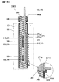
- FIG. 4 is a schematic cross-sectional view of a semiconductor module cut along a line IVa-IVa in FIG.
- the circuit diagram which shows the circuit structure of a semiconductor module.
- the perspective view of the conductor board assembly which removed the sealing resin of the semiconductor module.
- the perspective view of the conductor board assembly which removed the 1st conductor board and the 3rd conductor board of FIG.
- the flowchart which shows the manufacture procedure of a semiconductor module. Explanatory drawing explaining the coating film formed with a coating solution. Explanatory drawing explaining formation of a coating layer.
- FIG. 10 is a partial enlarged schematic view of a semiconductor module according to Modification 1.
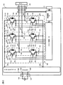
- FIG. 1 is a diagram showing a control block of a hybrid vehicle.
- Engine EGN and motor generator MG1 generate vehicle running torque.
- Motor generator MG1 not only generates rotational torque but also has a function of converting mechanical energy applied from the outside to motor generator MG1 into electric power.
- the motor generator MG1 is, for example, a synchronous machine or an induction machine, and operates as a motor or a generator depending on the operation method as described above.
- motor generator MG1 When motor generator MG1 is mounted on an automobile, it is desirable to obtain a small and high output, and a permanent magnet type synchronous motor using a magnet such as neodymium is suitable.
- the permanent magnet type synchronous motor generates less heat from the rotor than the induction motor, and is excellent for automobiles from this viewpoint.
- the output torque of the engine EGN is transmitted to the motor generator MG1 via the power distribution mechanism TSM, and the rotational torque from the power distribution mechanism TSM or the rotational torque generated by the motor generator MG1 is transmitted to the wheels via the transmission TM and the differential gear DIF. Communicated.
- rotational torque is transmitted from the wheels to motor generator MG1, and AC power is generated based on the supplied rotational torque.
- the generated AC power is converted to DC power by the power conversion device 200 as described later, and the high-voltage battery 136 is charged, and the charged power is used again as travel energy.
- the inverter circuit 140 is electrically connected to the battery 136 via the DC connector 138, and power is exchanged between the battery 136 and the inverter circuit 140.
- motor generator MG1 When motor generator MG1 is operated as a motor, inverter circuit 140 generates AC power based on DC power supplied from battery 136 via DC connector 138 and supplies it to motor generator MG1 via AC terminal 188. .
- the configuration including motor generator MG1 and inverter circuit 140 operates as a motor generator unit.
- the vehicle can be driven only by the power of the motor generator MG1 by operating the motor generator unit as an electric unit by the electric power of the battery 136.
- the battery 136 can be charged by operating the motor power generation unit as the power generation unit by the power of the engine EGN or the power from the wheels to generate power.
- the power conversion device 200 includes a capacitor module 500 for smoothing DC power supplied to the inverter circuit 140.
- the power conversion device 200 includes a communication connector 21 for receiving a command from a host control device or transmitting data representing a state to the host control device.
- Power conversion device 200 calculates a control amount of motor generator MG1 by control circuit 172 based on a command from connector 21, further calculates whether to operate as a motor or a generator, and controls based on the calculation result.
- a pulse is generated and the control pulse is supplied to the driver circuit 174.
- the driver circuit 174 generates a driving pulse for controlling the inverter circuit 140 based on the supplied control pulse.
- an insulated gate bipolar transistor Insulated Gate Bipolar Transistor
- IGBT Insulated Gate Bipolar Transistor
- the upper arm IGBT 328 and the diode 156, and the lower arm IGBT 330 and the diode 166 constitute a series circuit 150 of the upper and lower arms.
- the inverter circuit 140 includes the series circuit 150 corresponding to three phases of the U phase, the V phase, and the W phase of the AC power to be output.
- These three phases correspond to the three-phase windings of the armature winding of the motor generator MG1 in this embodiment.
- the series circuit 150 of the upper and lower arms of each of the three phases outputs an alternating current from the intermediate electrode 169 that is the midpoint portion of the series circuit.
- Intermediate electrode 169 is connected to AC bus bar 802 which is an AC power line to motor generator MG1 through AC terminal 159 and AC terminal 188.
- the collector electrode of the IGBT 328 of the upper arm is electrically connected to the capacitor terminal 506 on the positive electrode side of the capacitor module 500 via the DC positive electrode terminal 157.
- the emitter electrode of the IGBT 330 on the lower arm is electrically connected to the capacitor terminal 504 on the negative electrode side of the capacitor module 500 via the DC negative electrode terminal 158.
- control circuit 172 receives a control command from the host control device via the connector 21, and based on this, the IGBT 328 that configures the upper arm or the lower arm of each phase series circuit 150 that constitutes the inverter circuit 140. And a control pulse that is a control signal for controlling the IGBT 330 is generated and supplied to the driver circuit 174.
- the driver circuit 174 supplies a drive pulse for controlling the IGBT 328 and IGBT 330 constituting the upper arm or lower arm of each phase series circuit 150 to the IGBT 328 and IGBT 330 of each phase based on the control pulse.
- IGBT 328 and IGBT 330 perform conduction or cutoff operation based on the drive pulse from driver circuit 174, convert DC power supplied from battery 136 into three-phase AC power, and supply the converted power to motor generator MG1. Is done.
- Each of the upper arm IGBT 328 and the lower arm IGBT 330 includes a collector electrode, a signal emitter electrode, and a gate electrode.
- An upper arm diode 156 is electrically connected between the collector electrode terminal 153 and the emitter electrode terminal 155.
- a diode 166 is electrically connected between the collector electrode terminal 163 and the emitter electrode terminal 165.
- MOSFET metal oxide semiconductor field effect transistor
- IGBT is suitable when the DC voltage is relatively high
- MOSFET is suitable when the DC voltage is relatively low.
- the capacitor module 500 includes a positive capacitor terminal 506, a negative capacitor terminal 504, a positive power terminal 509, and a negative power terminal 508.
- the high-voltage DC power from the battery 136 is supplied to the positive-side power terminal 509 and the negative-side power terminal 508 via the DC connector 138, and the positive-side capacitor terminal 506 and the negative-side capacitor of the capacitor module 500.
- the voltage is supplied from the terminal 504 to the inverter circuit 140.
- the DC power converted from the AC power by the inverter circuit 140 is supplied to the capacitor module 500 from the positive capacitor terminal 506 and the negative capacitor terminal 504, and is connected to the positive power terminal 509 and the negative power terminal 508. Is supplied to the battery 136 via the DC connector 138 and accumulated in the battery 136.
- the control circuit 172 includes a microcomputer (hereinafter referred to as “microcomputer”) for performing arithmetic processing on the switching timing of the IGBT 328 and the IGBT 330.
- the input information to the microcomputer includes a target torque value required for the motor generator MG1, a current value supplied from the series circuit 150 to the motor generator MG1, and a magnetic pole position of the rotor of the motor generator MG1.
- the target torque value is based on a command signal output from a host controller (not shown).
- the current value is detected based on a detection signal from the current sensor 180.
- the magnetic pole position is detected based on a detection signal output from a rotating magnetic pole sensor (not shown) such as a resolver provided in the motor generator MG1.
- the current sensor 180 detects the current value of the three phases as an example, but the current value for the two phases may be detected and the current for the three phases may be obtained by calculation. .
- the microcomputer in the control circuit 172 calculates the d-axis and q-axis current command values of the motor generator MG1 based on the target torque value, the calculated d-axis and q-axis current command values, and the detected d
- the voltage command values for the d-axis and the q-axis are calculated based on the difference between the current values of the axes and the q-axis, and the calculated voltage command values for the d-axis and the q-axis are calculated based on the detected magnetic pole position. It is converted into voltage command values for phase, V phase, and W phase.
- the microcomputer generates a pulse-like modulated wave based on a comparison between the fundamental wave (sine wave) and the carrier wave (triangular wave) based on the voltage command values of the U phase, V phase, and W phase, and the generated modulation wave
- the wave is output to the driver circuit 174 as a PWM (pulse width modulation) signal.
- the driver circuit 174 When driving the lower arm, the driver circuit 174 outputs a drive signal obtained by amplifying the PWM signal to the gate electrode of the corresponding IGBT 330 of the lower arm. Further, when driving the upper arm, the driver circuit 174 amplifies the PWM signal after shifting the level of the reference potential of the PWM signal to the level of the reference potential of the upper arm, and uses this as a drive signal as a corresponding upper arm. Are output to the gate electrodes of the IGBTs 328 respectively.
- Information on the temperature of the series circuit 150 is input to the microcomputer from a temperature sensor (not shown) provided in the series circuit 150.
- voltage information on the DC positive side of the series circuit 150 is input to the microcomputer.
- the microcomputer performs overtemperature detection and overvoltage detection based on the information, and stops switching operations of all the IGBTs 328 and IGBTs 330 when an overtemperature or overvoltage is detected.
- the configuration of the semiconductor modules 300a to 300c used in the inverter circuit 140 will be described with reference to FIGS. Since the semiconductor modules 300a to 300c (see FIG. 2) all have the same structure, the structure of the semiconductor module 300a (hereinafter referred to as the semiconductor module 300A) will be described as a representative.
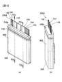
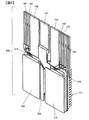
- FIG. 3 is a perspective view of the semiconductor module 300A.
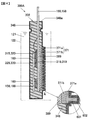
- FIG. 4 is a schematic cross-sectional view of the semiconductor module 300A, which is a schematic cross-sectional view taken along line IVa-IVa in FIG. In FIG. 4, the reference numerals of the constituent members shown in the section cut along the line IVb-IVb are also appended.
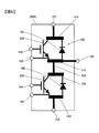
- FIG. 5 is a circuit diagram showing a circuit configuration of the semiconductor module 300A.
- FIG. 6 is a perspective view of the conductor plate assembly 950 from which the sealing resin 348 of the semiconductor module 300A has been removed to facilitate understanding.
- FIG. 7 is a perspective view of the conductor plate assembly 950 from which the first conductor plate 315 and the third conductor plate 320 of FIG. 6 are removed.
- the semiconductor module 300A includes power semiconductor elements (IGBT 328, IGBT 330, diode 156, and diode 166) that constitute the series circuit 150 shown in FIGS. 2 and 5, and these power semiconductor elements are It is sealed with a sealing resin 348 made of resin.
- the collector electrode of the IGBT 328 on the upper arm side and the cathode electrode of the diode 156 on the upper arm side are connected via a first conductor plate 315.
- the collector electrode of the IGBT 330 on the lower arm side and the cathode electrode of the diode 166 on the lower arm side are connected via the third conductor plate 320.
- the emitter electrode of the IGBT 328 on the upper arm side and the anode electrode of the diode 156 on the upper arm side are connected via the second conductor plate 318.
- the emitter electrode of the IGBT 330 on the lower arm side and the anode electrode of the diode 166 on the lower arm side are connected via a fourth conductor plate 319.
- the second conductor plate 318 and the third conductor plate 320 are connected by an intermediate electrode 329.
- the power semiconductor elements (IGBT 328, IGBT 330, diode 156, and diode 166) have a plate-like flat structure, and each electrode of the power semiconductor element is formed on the front and back surfaces.
- each electrode of the power semiconductor element has a first conductor plate 315 and a second conductor plate 318, or a third conductor plate 320 and a fourth conductor, which are arranged to face the respective electrode surfaces. It is sandwiched between the conductor plates 319. That is, the first conductor plate 315 and the second conductor plate 318 are stacked so as to face each other substantially in parallel via the IGBT 328 and the diode 156. Similarly, the third conductor plate 320 and the fourth conductor plate 319 have a stacked arrangement facing each other substantially in parallel via the IGBT 330 and the diode 166. As shown in FIG. 6, the third conductor plate 320 and the second conductor plate 318 are connected via an intermediate electrode 329. By this connection, the upper arm circuit and the lower arm circuit are electrically connected to form an upper and lower arm series circuit.
- the first conductor plate 315 on the DC side and the third conductor plate 320 on the AC side are arranged in substantially the same plane.
- the collector electrode of the IGBT 328 on the upper arm side and the cathode electrode of the diode 156 on the upper arm side are fixed.
- the collector electrode of the IGBT 330 on the lower arm side and the cathode electrode of the diode 166 on the lower arm side are fixed.
- the second conductor plate 318 on the AC side and the fourth conductor plate 319 on the DC side are arranged in substantially the same plane.
- the emitter electrode of the IGBT 328 on the upper arm side and the anode electrode of the diode 156 on the upper arm side are fixed to the second conductor plate 318.
- an emitter electrode of the IGBT 330 on the lower arm side and an anode electrode of the diode 166 on the lower arm side are fixed.
- a DC positive terminal 157 extends from the first conductor plate 315, an AC terminal 159 extends from the second conductor plate 318, and a DC negative terminal 158 extends from the fourth conductor plate 319.
- Each of the conductor plates 315, 318, 319, and 320 according to the present embodiment is a wiring for a large current circuit, and is made of a material having high thermal conductivity and low electrical resistance such as pure copper or copper alloy, and has a thickness of 0. .5 mm or more is preferable.
- each power semiconductor element is bonded to each of the conductor plates 315, 318, 319, and 320 via a metal bonding material 160.
- the metal bonding material 160 is, for example, a low-temperature sintered bonding material containing a silver sheet or fine metal particles, or lead-free solder having a high thermal conductivity and excellent environmental properties, such as Sn—Cu solder, Sn—Ag. -Cu solder, Sn-Ag-Cu-Bi solder and the like.
- the gate electrode terminals 154 and 164 and the emitter electrode terminals 155 and 165 for connection to the driver circuit 174 are connected to the gate electrode and the emitter electrode of the power semiconductor element by wire bonding, ribbon bonding or the like. It is preferable to use aluminum or gold for the wire or ribbon. Instead of wires or ribbons, connection may be made using solder or the like.
- the gate electrode terminals 154 and 164 and the emitter electrode terminals 155 and 165 are preferably made of pure copper or a copper alloy.
- the DC positive terminal 157, the DC negative terminal 158 and the AC terminal 159, the gate electrode terminals 154 and 164, the emitter electrode terminals 155 and 165, the current detection terminal, the temperature detection terminal, etc. are arranged in a line. These are connected by a tie bar 951 made of an insulating resin or the like at a predetermined interval and are integrally held.
- the semiconductor module 300 ⁇ / b> A includes heat radiating fins 371.
- the radiation fin 371 includes a fin plate 371a and a reinforcing plate 371b that increases the rigidity of the fin plate 371a.
- the fin plate 371a has a rectangular flat base and a plurality of columnar fins protruding from one surface of the base.
- the reinforcing plate 371b has a rectangular flat plate shape, and the outer shape of the reinforcing plate 371b is substantially the same as the outer shape of the base portion of the fin plate 371a.
- the base portion of the fin plate 371a and the reinforcing plate 371b are positioned and joined so that the outer peripheral side surface of the base portion of the fin plate 371a and the outer peripheral side surface of the reinforcing plate 371b are flush with each other.
- the semiconductor module 300 ⁇ / b> A is disposed in the case 122, and the heat radiating fins 371 exchange heat with the refrigerant 121 in the case 122 to radiate heat generated in the semiconductor module to the refrigerant 121.
- the refrigerant 121 flows in a direction orthogonal to the fins and circulates in the case 122 by a circulation device (not shown).
- An insulating plate 389 having an insulating property is bonded to the outer surfaces of the second conductor plate 318 and the fourth conductor plate 319 (the surface opposite to the bonding surface of the semiconductor element), and the reinforcing plate 371b is connected to the outer surface of the insulating plate 389.
- the fin plate 371a is joined to the exposed surface of the reinforcing plate 371b after transfer molding, which will be described later. That is, the surface of the fin plate 371a where the fins are formed is exposed from the sealing resin 348.
- the insulating plate 389 is made of an inorganic compound such as insulating ceramics or an organic compound such as insulating resin, and is disposed between the heat radiation fins 371 and the conductor plates 318 and 319 to insulate them.
- the material of the insulating plate 389 is preferably selected to have a high thermal conductivity.
- the insulating plate 389 is connected to the conductor plates 318 and 319 and the reinforcing plate 371b in a state before the resin component is completely cured, that is, in a state having adhesiveness. Note that the insulating plate 389 can be omitted when the reinforcing plate 371b and the fin plate 371a constituting the heat radiation fin 371 are formed of an insulating material.
- the reinforcing plate 371b and the fin plate 371a are made of a metal material having a higher thermal conductivity than a material used for the sealing resin 348, such as aluminum, copper, or magnesium, or a ceramic material such as alumina.
- a material used for the sealing resin 348 such as aluminum, copper, or magnesium
- a ceramic material such as alumina.
- the material of the reinforcing plate 371b it is preferable to select a material having higher rigidity than the material of the fin plate 371a. In the present embodiment, different materials are selected for the reinforcing plate 371b and the fin plate 371a.
- the second conductor plate 318 or the fourth conductor plate 319, the insulating plate 389, the reinforcing plate 371b, and the fin plate 371a are joined by welding, soldering, friction stir welding (FSW: Friction Stir Welding) or the like. If the strength of the fin plate 371a is sufficient, the reinforcing plate 371b can be omitted.
- the second conductor plate 318 and the fourth conductor plate 319 are coupled to the heat radiation fins 371 through the insulating plates 389 so as to be able to conduct heat.
- the heat generated in the semiconductor elements 156, 166, 328, and 330 is transmitted to the second conductor plate 318 or the fourth conductor plate 319, is transmitted to the radiation fins 371 through the insulating plate 389, and the coating layer 601 described later from the radiation fins 371.
- the heat is radiated to the refrigerant 121 through the waterproof layer 602.
- the semiconductor structure 302 is formed by molding the conductor plate assembly 950 with an insulating sealing resin 348 by a transfer molding method or the like.
- a conductive plate assembly 950 is fixed in a preheated mold, and a power semiconductor is formed by injecting pressure into the mold while melting a thermosetting resin such as an epoxy resin.
- the conductor plate assembly 950 including the elements is sealed with a sealing resin 348 to form a semiconductor structure (module sealing body) 302.
- the sealing resin 348 has a terminal surface 348 a on which the terminals 157, 158, 159, 154, 155, 164, 165 are arranged in a state of being insulated from each other. .
- a very slight gap may be formed at the boundary between the sealing resin 348 and the conductor plate assembly 950 on the surface of the semiconductor structure 302.
- the gaps (dents) are often in the range of 1 to 500 ⁇ m in width and 1 to 500 ⁇ m in depth, and may be elongated along the boundary surface in the depth direction.
- the coating layer 601 that covers the gap and the waterproof layer 602 that is formed on the surface of the coating layer 601 are formed on the outer surface of the semiconductor structure 302.
- the region where the coating layer 601 is formed is a region including the entire contact region of the coolant 121 in the semiconductor structure 302.
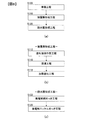
- FIG. 8 is a flowchart showing a manufacturing procedure of the semiconductor module 300A.
- the semiconductor module 300A includes a preparation step S100 for preparing the semiconductor structure 302, a covering layer forming step S110 for forming the covering layer 601, and a waterproof layer forming step S120 for forming the waterproof layer 602. It is made after.
- the coating layer forming step S110 includes a coating solution preparation step S112, an immersion step S115, and a heat curing step S118.
- a coating solution is prepared by diluting and adjusting a commercially available polyamideimide with N-methyl-2-pyrrolidone so that the viscosity is 6% by weight and the viscosity is 0.3 Pa ⁇ s.
- -Immersion step S115- After covering portions other than the coating area, for example, the terminal surface 348a and each terminal in the vicinity of the terminal surface with a curing member (not shown) such as a curing tape, a curing sheet, and a curing jig, a semiconductor structure is formed by dipping.
- the body 302 is immersed in the coating solution and coated. At this time, the amount of the coating solution and the height of immersion are adjusted so that the terminal surface 348a is not immersed.
- the solvent N-methyl-2-pyrrolidone
- the resin polyamideimide
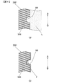
- FIG. 9 is an explanatory diagram for explaining the coating film F formed by the coating solution L.
- the coating film F is formed in a horizontal state with the opening surface of the depression S0 facing upward is shown. ing.
- a depression S0 is formed on the surface of the sealing resin 348 due to voids generated during molding.
- FIG. 9A when the semiconductor structure 302 is immersed in the coating solution L with the terminal side facing up, and then the semiconductor structure 302 is pulled up, as shown in FIG.
- the coating solution L flows down from the ceiling surface (upper side surface) of the film, and the thickness of the coating film F adhering to the bottom surface (lower side surface) becomes thicker than the ceiling surface of the depression S0.
- the viscosity of the coating solution L is less than 0.1 Pa ⁇ s, the coating solution L applied to the depression S0 flows down, and a part of the inner surface of the depression S0 is exposed.
- the viscosity of the coating solution L exceeds 100 Pa ⁇ s, the coating solution L cannot be put into the depression S0, and the embedding effect is lost. For this reason, it is preferable that the viscosity of the coating solution L is 0.1 Pa ⁇ s or more and 100 Pa ⁇ s or less.
- FIG. 10 is an explanatory diagram for explaining the formation of the coating layer 601.
- a coating film F is formed with the coating solution L (see FIG. 9), and the depression S0 is covered with the coating film F.
- the coating layer F 601 is formed by heating and curing the coating film F for a predetermined time, as shown in FIG.
- the thickness of the coating film F is Y and the resin content is C wt%
- the thickness of the coating layer 601 is C ⁇ Y
- the thickness of the coating layer 601 in the depression S0 is C ⁇ (Y + Z0).
- the depth Z1 of the depression S1 of the coating layer 601 is expressed by the following formula (1).
- the coating solution L can be composed of various components, but as represented by the formula (1), the greater the resin content C, the higher the effect of filling the depression S0. In the case of less than 5% by weight, since the effect of filling the depression S0 is small, the resin content C is desirably 5% by weight or more and 100% by weight or less. Thus, since the effect of reducing the height of the dent is obtained by the coating layer 601, the coating layer 601 functions as a planarization layer that flattens the surface of the sealing resin 348.
- the waterproof layer forming step S120 includes an electroless copper plating step S122 and an electroless nickel plating step S125.
- -Electroless copper plating process S122- A 0.5 ⁇ m-thick copper film is formed as a base film by electroless copper plating.
- -Electroless nickel plating process S125- A nickel film having a thickness of 20 ⁇ m is formed on the base film by electroless nickel plating, and a waterproof layer 602 made of a copper film and a nickel film is formed as shown in the enlarged view of part A in FIG.
- the base film can be omitted, it is preferable to form the base film because the base film can improve adhesion with the coating layer 601 made of an organic compound.
- the curing member is removed to complete the semiconductor module 300A.
- the thickness of the waterproof layer 602 is preferably 500 ⁇ m or less.
- the semiconductor module 300A can conduct heat through the semiconductor elements 328, 330, 156, and 166, the conductor plates 318 and 319 to which the semiconductor elements are joined, and the semiconductor elements through the conductor plates 318 and 319 and the insulating plate 389.
- the semiconductor structure 302 including the heat radiation fin 371 fixed to the heat radiation fin 371 and the sealing resin 348 that is made of a different material from the heat radiation fin 371 and exposes one surface of the heat radiation fin 371 to seal the semiconductor element, and at least the refrigerant 121.
- the coating layer 601 that covers the boundary between the heat radiation fin 371 and the sealing resin 348 in the contact area of the contact layer 601 and a waterproof layer 602 that is made of a material different from the coating layer 601 and is formed on the surface of the coating layer 601.
- a gap (dent) formed along the boundary between the sealing resin 348 and the heat radiation fin 371 is covered.
- the waterproof layer 602 the refrigerant 121 can be prevented from entering the sealing resin 348, so that the life of the semiconductor module 300A can be extended.
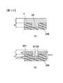
- FIG. 11A is a partial cross-sectional schematic view showing a state after molding of the sealing resin 348, and FIG. 11B directly waterproofs the surface of the semiconductor structure 302 without providing the covering layer 601.
- FIG. 6 is a partial cross-sectional schematic diagram showing an example in which a layer 602 is provided (hereinafter referred to as a comparative example).
- FIG. 12 is a partial cross-sectional schematic diagram showing this embodiment in which a covering layer 601 and a waterproof layer 602 are provided.
- FIGS. 11A, 11B, and 12 schematically show a cross section of a portion corresponding to the portion A of FIG.
- FIG. 11A after molding of the sealing resin 348, an extremely slight gap G is formed on the boundary surface between the sealing resin 348 and the reinforcing plate 371 b of the radiating fin 371 due to thermal contraction of the sealing resin 348. May occur.
- the covering layer 601 is not formed, and the waterproof layer is composed of a 0.5 ⁇ m copper film and a 20 ⁇ m nickel film by electroless copper plating and electroless nickel plating. 602 is formed.
- the comparative example as shown in FIG.
- the gap G is not sufficiently covered, and the refrigerant 121 enters along the boundary surface between the radiating fin 371 and the sealing resin 348, and the leakage current of the semiconductor element is reduced.
- the verification result that it increased and cannot start normally was obtained.
- the covering layer 601 is covered with the covering layer 601 so as to fill the gap (dent) G, and the waterproof layer 602 is formed on the surface of the covering layer 601. Therefore, the infiltration of the refrigerant 121 can be prevented, and the semiconductor module 300A can be normally operated over a long period of time. Since the coating layer 601 that fills the depressions S0 and G existing on the surface is provided, the adhesiveness of the waterproof layer 602 is improved and the reliability is improved as compared with the comparative example.
- the covering layer 601 is formed on the entire contact area of the refrigerant 121 including the boundary between the heat radiation fin 371 and the sealing resin 348, and the waterproof layer 602 is formed on the surface of the covering layer 601. Yes. Accordingly, direct contact of the coolant 121 with the sealing resin 348 can be prevented over the entire contact area of the coolant 121, and the life of the semiconductor module 300A can be extended.
- the coating layer 601 is formed of an organic compound, a depression of several ⁇ m to several hundred ⁇ m can be covered. For this reason, even if there are variations in the width (depth) of the gaps (dents) formed at the boundary between the radiation fins 371 and the sealing resin 348 and the widths and depths of the plurality of depressions formed on the surface of the sealing resin 348, Can be covered with a covering layer 601.
- the waterproof layer 602 is made of metal, the refrigerant 121 can be blocked and the refrigerant 121 can be prevented from coming into direct contact with the coating layer 601.
- FIG. 13 is a perspective view of the semiconductor module 300B according to the second embodiment, which is the same diagram as FIG.
- FIG. 14 is a view similar to FIG. 4 and is a schematic cross-sectional view of a semiconductor module 300B according to the second embodiment.
- the same or corresponding parts as those in the first embodiment are denoted by the same reference numerals, and description thereof is omitted.
- differences from the first embodiment will be described in detail.
- the radiating fins 371 are provided only on one surface of the semiconductor module 300A.
- the radiating fins 371 are provided on both surfaces of the semiconductor module 300B. Is provided.
- an insulating plate 389 having insulating properties is joined to the outer surfaces of the first conductor plate 315 and the third conductor plate 320, and a reinforcing plate 371b is joined to the outer surface of the insulating plate 389.
- the fin plate 371a is joined to the exposed surface of the reinforcing plate 371b.
- the insulating plate 389 is made of an inorganic compound such as insulating ceramics or an organic compound such as insulating resin, and is disposed between the heat radiation fins 371 and the conductor plates 315 and 320 to insulate them.
- the material of the insulating plate 389 is preferably selected to have a high thermal conductivity.
- the insulating plate 389 is formed of resin, it is preferable that the insulating plate 389 is connected to the conductor plates 315 and 320 and the reinforcing plate 371b in a state before the resin component is completely cured, that is, in a state having adhesiveness. Note that the insulating plate 389 can be omitted when the reinforcing plate 371b and the fin plate 371a constituting the heat radiation fin 371 are formed of an insulating material.
- the reinforcing plate 371b and the fin plate 371a are made of a metal material having a higher thermal conductivity than a material used for the sealing resin 348, such as aluminum, copper, or magnesium, or a ceramic material such as alumina.
- a material used for the sealing resin 348 such as aluminum, copper, or magnesium
- a ceramic material such as alumina.
- the first conductor plate 315 or the third conductor plate 320, the insulating plate 389, the reinforcing plate 371b, and the fin plate 371a are joined by welding, soldering, friction stir welding, or the like. If the strength of the fin plate 371a is sufficient, the reinforcing plate 371b can be omitted.
- the same effects as those of the first embodiment can be obtained.
- the cooling performance can be improved as compared with the first embodiment.
- FIG. 15 is a view similar to FIG. 4 and is a schematic cross-sectional view of a semiconductor module 300C according to the third embodiment.
- the same or corresponding parts as those in the first embodiment are denoted by the same reference numerals, and description thereof is omitted.
- differences from the first embodiment will be described in detail.
- each terminal is arranged on one terminal surface 348a.
- a surface opposite to the one terminal surface 348a hereinafter, another terminal surface 348b.
- a DC negative terminal 158, a DC positive terminal 157 and an AC terminal 159, gate electrode terminals 154 and 164, and emitter electrode terminals 155 and 165 shown in FIG. 5 extend from one terminal surface 348a.
- the current detection terminal 190 extends from the other terminal surface 348b.
- the covering layer 601 and the waterproof layer 602 are formed on the two terminal surfaces 348a and 348b. Therefore, the area where the covering layer 601 and the waterproof layer 602 are not formed is increased as compared with the first embodiment.
- the two terminal surfaces 348a and 348b and the terminals are covered with a curing member, and the coating layer 601 is formed with a coating solution. Thereafter, the waterproof layer 602 is formed, and the curing member is removed.
- the same operational effects as those of the first embodiment can be obtained. Since the area where the covering layer 601 and the waterproof layer 602 are formed is smaller than that in the first embodiment, the weight and cost can be reduced as compared with the first embodiment.
- FIG. 16 is a view similar to FIG. 4 and is a schematic cross-sectional view of a semiconductor module 300D according to the fourth embodiment.
- the same or corresponding parts as those in the first embodiment are denoted by the same reference numerals, and description thereof is omitted.
- differences from the first embodiment will be described in detail.
- the covering layer 601 and the waterproof layer 602 are formed over the entire contact area of the coolant 121 in the semiconductor structure 302.
- the peripheral edge portion of the heat dissipating fins 371 is used. Except for the above, the covering layer 601 and the waterproof layer 602 are not formed on the radiation fin 371.
- the coating layer 601 is formed by immersing the coating fin solution 371 in a state where the surface of the radiation fin 371 is covered with a curing member. Thereafter, the waterproof layer 602 is formed, and the curing member is removed.
- a coating layer 601 and a waterproof layer 602 are formed on the peripheral portion of the fin plate 371 a, that is, on the radiation fin 371 in the vicinity of the boundary between the radiation fin 371 and the sealing resin 348.
- the covering layer 601 and the waterproof layer 602 are formed over the entire contact area of the refrigerant 121 in the sealing resin 348, but the covering layer 601 and the waterproof layer 602 are formed on the heat radiation fin 371. Is exposed.
- the heat radiation fin 371 can be directly contacted with a refrigerant
- coolant and heat exchange can be performed, there exists an effect that the heat dissipation effect can be heightened more. Further, the weight and cost can be reduced as compared with the first embodiment.
- a configuration in which the radiating fins 371 are in contact with the refrigerant can be employed.
- the positional relationship among the fin plate 371a, the reinforcing plate 371b, and the insulating plate 389 is not limited to the above-described embodiment.
- the outer shape of the reinforcing plate 371b may be made slightly larger than the outer shape of the fin plate 371a.
- the size of the reinforcing plate 371b is made larger than that of the fin plate 371a, so that the sealing resin 348 and the reinforcing plate at the boundary (B1 portion) between the sealing resin 348 and the reinforcing plate 371b. It can be a portion where three different members 371b and the covering layer 601 intersect. Thereby, compared with the first embodiment in which four different members intersect, stress concentration at the intersection (B1 portion) can be relaxed.
- the present invention is not limited to the case where the fin plate 371a, the reinforcing plate 371b, and the insulating plate 389 are made of different materials.
- the reinforcing plate 371b and the fin plate 371a are formed with the same material, there are three different members at the boundary (B1 portion) between the sealing resin 348 and the reinforcing plate 371b. Will be crossed. For this reason, compared with the structure where four different members cross, stress concentration can be eased.
- FIG.17 (c) when the reinforcement board 371b is abbreviate
- the coating layer 601 is formed from polyamideimide.
- the coating layer 601 can be formed of various thermosetting resins such as polyimide, polyimidazole, phenol resin, epoxy resin, and melamine resin.
- the coating solution is composed of at least a solvent and a resin component.
- a methyl ethyl ketone solution having a viscosity of 30 Pa ⁇ s with 20 wt% epoxy resin is prepared, and then the surface of the semiconductor structure 302 is coated using this coating solution.
- the coating layer 601 is formed by heat-curing at 150 ° C. for 1 hour.
- the coating layer 601 is formed by the dipping method immersed in the coating solution has been described, but the present invention is not limited to this.
- the method of applying the coating solution is not limited to immersion, and the coating layer 601 may be formed by applying the coating solution to the semiconductor structure 302 by spraying or brushing. Dip (dipping), spraying, brushing, or combinations thereof can also be used. If the embeddability is insufficient, it can be improved by overcoating.
- the covering layer 601 may be formed of an inorganic compound.
- the coating layer 601 can be formed without waste by forming the thin coating layer 601 with an inorganic compound.
- the coating layer 601 can be formed of an inorganic compound such as silicon oxide, titanium oxide, or zirconium oxide. These are thermally cured using tetraethoxysilane, tetrabutoxytitanium, zirconium (IV) propoxide, or the like to form an oxide film. Since heating to the boiling point of the solvent used is sufficient for thermosetting, it can be formed without damaging the semiconductor chip or the sealing resin 348 unlike the glass coating.
- the solvent is selected according to the inorganic compound.
- alcohol solvents such as ethanol, propanol, butanol, hexanol, pentanol, toluene, xylene, cyclohexansan, and the like can be selected as the solvent.
- Acetic acid may be added to obtain the stability of the diluted solution.
- an inorganic element ratio shall be 2 weight% or less with respect to the whole coating solution.
- the inorganic element ratio is 2% by weight or less with respect to the entire coating solution, no chemical change occurs and the coating solution can be used as a stable coating solution.
- dipping dipping
- spraying brushing, or a combination thereof can be used as a coating layer formation method with an inorganic compound. If the embeddability is insufficient, it can be improved by overcoating.
- an ethanol solution of 1 wt% tetraethoxysilane is prepared, and then the coating solution is sprayed onto the semiconductor structure 302 by spraying to form a coating film.
- a silicon oxide film is formed by heat curing at 100 ° C. for 1 hour. By repeating this process about two or three times, the covering layer 601 is formed to cover the depressions S0 and G.
- the coating layer 601 As another example of forming the coating layer 601 with an inorganic compound, a toluene solution of 1% by weight tetrabutoxytitanium is prepared, and then the semiconductor structure 302 is immersed in this coating solution (dip method) to form a coating film. . After the dip coating, the coating is cured by heating at 80 ° C. and 120 ° C. for 1 hour to form a titanium oxide film. By repeating this process about two or three times, the covering layer 601 is formed to cover the depressions S0 and G.
- the covering layer 601 may be formed of a metal such as chromium, titanium, copper, and alloys thereof.
- the coating layer (metal film) made of metal can be formed by sputtering, vapor deposition, electroless plating, or the like.
- the metal film not only has a function of covering the recesses S0 and G so as to fill the recesses S0 and G, but also has a function of improving adhesion to the waterproof layer 602 made of metal.
- a chromium film having a thickness of 0.1 ⁇ m was formed as a base film by a sputtering method, and then a copper film having a thickness of 1 ⁇ m was formed. Sputtering is performed on each surface of the semiconductor structure 302 that forms the coating layer 601, for example, so that the distance from the target metal is constant and a uniform metal film can be obtained.
- the material is not limited to copper (Cu) or nickel (Ni), but includes tin (Sn), zinc (Zn), and an alloy containing copper, nickel, tin, and zinc (for example, nickel phosphorus (Ni-P) alloy) Nickel boron (Ni—B) alloy, nickel phosphorus boron (Ni—P—B) multi-component alloy) can be used.
- Nickel is particularly excellent in corrosion resistance, and copper is particularly excellent in thermal conductivity. Therefore, it is preferable to select according to the application.
- the waterproof layer 602 may be formed by electroplating or a combination of electroless plating and electroplating. This is because electroless plating and electroplating are not only suitable for mass production, but also cause less damage to the semiconductor structure 302 than methods such as cold spraying and thermal spraying.
- the radiating fins 371 and the insulating plate 389 are configured as heat transfer members that transmit the heat of the conductor plates 318, 319, 315, and 320 has been described, but the present invention is not limited thereto. .
- a sheet-like insulating sheet may be provided.
- the reinforcing plate 371b of the radiating fin 371 may be formed of an insulating material and the insulating plate 389 may be omitted.
- the fin shape of the heat radiation fin 371 is not limited to a cylindrical shape, and various fin shapes can be employed.
- a flat heat radiating plate having no fins may be employed.
- the power conversion device inverter
- the present invention is not limited to this.
- the present invention can be applied to various electronic control devices including a semiconductor module.
- the present invention is not limited to the above-described embodiments, and other forms conceivable within the scope of the technical idea of the present invention are also included in the scope of the present invention. .
Landscapes
- Cooling Or The Like Of Semiconductors Or Solid State Devices (AREA)
Abstract
半導体モジュールにおける防水効果の向上を図る。 半導体モジュールは、半導体素子と、半導体素子が接合された導体部材と、半導体素子に熱伝導可能に設けられた放熱部材と、放熱部材とは異なる材質からなり、放熱部材の一面を露出して半導体素子を封止する封止材とを備える半導体構造体と、少なくとも冷媒の接触領域内における放熱部材と封止材との境界を覆う被覆層と、被覆層とは異なる材質からなり、被覆層の表面に形成される防水層とを備える。
Description
本発明は、半導体モジュールおよび半導体モジュールの製造方法ならびに電子制御装置に関する。
近年、省エネルギー化の推進や低炭素社会の実現のため、電気自動車やハイブリッド自動車といった自動車の電動化が急速に進展している。特に、電動化システムの基本構成要素となるインバータの役割は今まで以上に多様化し、小型化と高出力化を同時に実現することが求められている。インバータには、その主要部品としてトランジスタやダイオード等のパワー半導体チップを樹脂で封止してなるパワー半導体モジュールが搭載されている。電気自動車、ハイブリッド自動車用のパワー半導体モジュールでは、デバイスの電流容量の増大や小型化による電流密度の増大に伴い、通電により発熱するため、パワー半導体モジュールの温度上昇を抑える冷却手段が設けられている。
パワー半導体モジュールなどの半導体装置の冷却方式として水冷方式が知られている(特許文献1参照)。特許文献1には、半導体装置の側面とケースの内壁とによって規定される空間が、半導体装置を冷却するための冷媒の流路を構成し、半導体装置が冷媒中に浸漬されている点が記載されている。また、特許文献1には、半導体装置の表面を覆う金属膜がめっきや半田付け等によって形成され、放熱性の向上と、冷媒に対する防水性を高めることが記載されている。
半導体モジュールでは、金属製の放熱板や放熱フィンなどの放熱部材を封止樹脂から露出させて、冷媒に接触させ、放熱効率を高めることが行われる。半導体モジュールの製造方法として、トランスファーモールド法がある。トランスファーモールド法では、半導体素子等を実装した基板を予め加熱された金型内に固定し、この金型にモールド樹脂を溶融させながら加圧注入し封止する。しかしながら、放熱部材と封止樹脂とが異種材料であるため、成形後、封止樹脂と放熱部材との境界面に極わずかな隙間が発生するおそれがある。
境界面に隙間が存在していると、めっき処理を施しても、隙間を覆うように金属膜を形成することができず、この隙間から冷媒が浸入してしまうという問題点がある。
請求項1に記載の半導体モジュールは、半導体素子と、半導体素子が接合された導体部材と、半導体素子に熱伝導可能に設けられた放熱部材と、放熱部材とは異なる材質からなり、放熱部材の一面を露出して半導体素子を封止する封止材とを備える半導体構造体と、少なくとも冷媒の接触領域内における放熱部材と封止材との境界を覆う被覆層と、被覆層とは異なる材質からなり、被覆層の表面に形成される防水層とを備える。
請求項8に記載の半導体モジュールの製造方法は、半導体素子と、半導体素子が接合された導体部材と、半導体素子に熱伝導可能に設けられた放熱部材と、放熱部材とは異なる材質からなり、放熱部材の一面を露出して半導体素子を封止する封止材とを備える半導体構造体を準備し、少なくとも冷媒の接触領域内における放熱部材と封止材との境界を覆う被覆層を形成し、被覆層の表面に被覆層とは異なる材質からなる防水層を形成する。
請求項8に記載の半導体モジュールの製造方法は、半導体素子と、半導体素子が接合された導体部材と、半導体素子に熱伝導可能に設けられた放熱部材と、放熱部材とは異なる材質からなり、放熱部材の一面を露出して半導体素子を封止する封止材とを備える半導体構造体を準備し、少なくとも冷媒の接触領域内における放熱部材と封止材との境界を覆う被覆層を形成し、被覆層の表面に被覆層とは異なる材質からなる防水層を形成する。
本発明によれば、防水効果の向上を図ることができる。
以下、図面を参照して本発明を実施するための形態について説明する。
-第1の実施の形態-
図1は、ハイブリッド自動車の制御ブロックを示す図である。エンジンEGNおよびモータジェネレータMG1は車両の走行用トルクを発生する。モータジェネレータMG1は回転トルクを発生するだけでなく、モータジェネレータMG1に外部から加えられる機械エネルギーを電力に変換する機能を有する。
-第1の実施の形態-
図1は、ハイブリッド自動車の制御ブロックを示す図である。エンジンEGNおよびモータジェネレータMG1は車両の走行用トルクを発生する。モータジェネレータMG1は回転トルクを発生するだけでなく、モータジェネレータMG1に外部から加えられる機械エネルギーを電力に変換する機能を有する。
モータジェネレータMG1は、たとえば同期機あるいは誘導機であり、上述のごとく、運転方法によりモータとしても発電機としても動作する。モータジェネレータMG1を自動車に搭載する場合には、小型で高出力を得ることが望ましく、ネオジウムなどの磁石を使用した永久磁石型の同期電動機が適している。永久磁石型の同期電動機は誘導電動機に比べて回転子の発熱が少なく、この観点でも自動車用として優れている。
エンジンEGNの出力トルクは動力分配機構TSMを介してモータジェネレータMG1に伝達され、動力分配機構TSMからの回転トルクあるいはモータジェネレータMG1が発生する回転トルクは、トランスミッションTMおよびデファレンシャルギアDIFを介して車輪に伝達される。一方、回生制動の運転時には、車輪から回転トルクがモータジェネレータMG1に伝達され、供給されてきた回転トルクに基づいて交流電力を発生する。発生した交流電力は後述するように電力変換装置200により直流電力に変換され、高電圧用のバッテリ136を充電し、充電された電力は再び走行エネルギーとして使用される。
次に半導体素子のスイッチング動作によって電力を直流から交流に、交流から直流に変換する電力変換装置200について説明する。インバータ回路140は、バッテリ136と直流コネクタ138を介して電気的に接続されており、バッテリ136とインバータ回路140との相互において電力の授受が行われる。モータジェネレータMG1をモータとして動作させる場合には、インバータ回路140は直流コネクタ138を介してバッテリ136から供給された直流電力に基づき交流電力を発生し、交流端子188を介してモータジェネレータMG1に供給する。モータジェネレータMG1とインバータ回路140からなる構成は電動発電ユニットとして動作する。
なお、本実施形態では、バッテリ136の電力によって電動発電ユニットを電動ユニットとして作動させることにより、モータジェネレータMG1の動力のみによって車両の駆動ができる。さらに、本実施形態では、電動発電ユニットを発電ユニットとしてエンジンEGNの動力あるいは車輪からの動力によって作動させて発電させることにより、バッテリ136の充電ができる。
電力変換装置200は、インバータ回路140に供給される直流電力を平滑化するためのコンデンサモジュール500を備えている。
電力変換装置200は、上位の制御装置から指令を受けたりあるいは上位の制御装置に状態を表すデータを送信したりするための通信用のコネクタ21を備えている。電力変換装置200は、コネクタ21からの指令に基づいて制御回路172でモータジェネレータMG1の制御量を演算し、さらにモータとして運転するか発電機として運転するかを演算し、演算結果に基づいて制御パルスを発生し、その制御パルスをドライバ回路174へ供給する。ドライバ回路174は、供給された制御パルスに基づいて、インバータ回路140を制御するための駆動パルスを発生する。
次に、図2を用いてインバータ回路140の電気回路の構成を説明する。なお、本実施形態では半導体素子として絶縁ゲート型バイポーラトランジスタ(Insulated Gate Bipolar Transistor)を使用しており、以下略してIGBTと記す。
上アームのIGBT328およびダイオード156と、下アームのIGBT330およびダイオード166とで、上下アームの直列回路150が構成される。インバータ回路140は、この直列回路150を、出力しようとする交流電力のU相、V相、W相の3相に対応して備えている。
これらの3相は、この実施の形態ではモータジェネレータMG1の電機子巻線の3相の各相巻線に対応している。3相のそれぞれの上下アームの直列回路150は、直列回路の中点部分である中間電極169から交流電流を出力する。この中間電極169は、交流端子159および交流端子188を通して、モータジェネレータMG1への交流電力線である交流バスバー802と接続される。
上アームのIGBT328のコレクタ電極は、直流正極端子157を介してコンデンサモジュール500の正極側のコンデンサ端子506に電気的に接続されている。また、下アームのIGBT330のエミッタ電極は、直流負極端子158を介してコンデンサモジュール500の負極側のコンデンサ端子504に電気的に接続されている。
上述のように、制御回路172は上位の制御装置からコネクタ21を介して制御指令を受け、これに基づいてインバータ回路140を構成する各相の直列回路150の上アームあるいは下アームを構成するIGBT328やIGBT330を制御するための制御信号である制御パルスを発生し、ドライバ回路174に供給する。
ドライバ回路174は、上記制御パルスに基づき、各相の直列回路150の上アームあるいは下アームを構成するIGBT328やIGBT330を制御するための駆動パルスを各相のIGBT328やIGBT330に供給する。IGBT328やIGBT330は、ドライバ回路174からの駆動パルスに基づき、導通あるいは遮断動作を行い、バッテリ136から供給された直流電力を三相交流電力に変換し、この変換された電力はモータジェネレータMG1に供給される。
上アームのIGBT328および下アームのIGBT330は、それぞれ、コレクタ電極と、信号用のエミッタ電極と、ゲート電極とを備えている。上アームのダイオード156が、コレクタ電極端子153とエミッタ電極端子155との間に電気的に接続されている。また、ダイオード166が、コレクタ電極端子163とエミッタ電極端子165との間に電気的に接続されている。
なお、スイッチング用パワー半導体素子としては金属酸化物半導体型電界効果トランジスタ(以下略してMOSFETと記す)を用いてもよい、この場合はダイオード156やダイオード166は不要となる。スイッチング用パワー半導体素子としては、IGBTは直流電圧が比較的高い場合に適していて、MOSFETは直流電圧が比較的低い場合に適している。
コンデンサモジュール500は、正極側のコンデンサ端子506と負極側のコンデンサ端子504と正極側の電源端子509と負極側の電源端子508とを備えている。バッテリ136からの高電圧の直流電力は、直流コネクタ138を介して、正極側の電源端子509や負極側の電源端子508に供給され、コンデンサモジュール500の正極側のコンデンサ端子506および負極側のコンデンサ端子504から、インバータ回路140へ供給される。
一方、交流電力からインバータ回路140によって変換された直流電力は、正極側のコンデンサ端子506や負極側のコンデンサ端子504からコンデンサモジュール500に供給され、正極側の電源端子509や負極側の電源端子508から直流コネクタ138を介してバッテリ136に供給され、バッテリ136に蓄積される。
制御回路172は、IGBT328およびIGBT330のスイッチングタイミングを演算処理するためのマイクロコンピュータ(以下、「マイコン」と記述する)を備えている。マイコンへの入力情報としては、モータジェネレータMG1に対して要求される目標トルク値、直列回路150からモータジェネレータMG1に供給される電流値、およびモータジェネレータMG1の回転子の磁極位置がある。
目標トルク値は、不図示の上位の制御装置から出力された指令信号に基づくものである。電流値は、電流センサ180による検出信号に基づいて検出されたものである。磁極位置は、モータジェネレータMG1に設けられたレゾルバなどの回転磁極センサ(不図示)から出力された検出信号に基づいて検出されたものである。本実施形態では、電流センサ180は3相の電流値を検出する場合を例に挙げているが、2相分の電流値を検出するようにし、演算により3相分の電流を求めてもよい。
制御回路172内のマイコンは、目標トルク値に基づいてモータジェネレータMG1のd軸、q軸の電流指令値を演算し、この演算されたd軸、q軸の電流指令値と、検出されたd軸、q軸の電流値との差分に基づいてd軸、q軸の電圧指令値を演算し、この演算されたd軸、q軸の電圧指令値を、検出された磁極位置に基づいてU相、V相、W相の電圧指令値に変換する。そして、マイコンは、U相、V相、W相の電圧指令値に基づく基本波(正弦波)と搬送波(三角波)との比較に基づいてパルス状の変調波を生成し、この生成された変調波をPWM(パルス幅変調)信号としてドライバ回路174に出力する。
ドライバ回路174は、下アームを駆動する場合、PWM信号を増幅したドライブ信号を、対応する下アームのIGBT330のゲート電極に出力する。また、ドライバ回路174は、上アームを駆動する場合、PWM信号の基準電位のレベルを上アームの基準電位のレベルにシフトしてからPWM信号を増幅し、これをドライブ信号として、対応する上アームのIGBT328のゲート電極にそれぞれ出力する。
直列回路150に設けられた温度センサ(不図示)からは直列回路150の温度の情報がマイコンに入力されている。また、マイコンには直列回路150の直流正極側の電圧の情報が入力されている。マイコンは、それらの情報に基づいて過温度検知および過電圧検知を行い、過温度あるいは過電圧が検知された場合には全てのIGBT328,IGBT330のスイッチング動作を停止させる。
図3~図7を参照して、インバータ回路140に使用される半導体モジュール300a~300cの構成を説明する。なお、上記半導体モジュール300a~300c(図2参照)はいずれも同じ構造であるため、代表して半導体モジュール300a(以下、半導体モジュール300Aと記す)の構造を説明する。
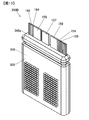
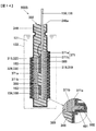
図3は半導体モジュール300Aの斜視図である。図4は半導体モジュール300Aの断面模式図であり、図3(a)のIVa-IVa線で切断した断面模式図である。なお、図4では、IVb-IVb線で切断した断面において表される構成部材の符号についても付記している。図5は、半導体モジュール300Aの回路構成を示す回路図である。図6は、理解を助けるために、半導体モジュール300Aの封止樹脂348を取り除いた導体板組み950の斜視図である。図7は、図6の第1導体板315および第3導体板320を取り除いた導体板組み950の斜視図である。
図4に示すように、半導体モジュール300Aは、図2および図5に示す直列回路150を構成するパワー半導体素子(IGBT328,IGBT330,ダイオード156,ダイオード166)を含んで構成され、これらパワー半導体素子が樹脂からなる封止樹脂348により封止されてなる。
図5を参照して半導体モジュールの回路構成について説明する。図5に示すように、上アーム側のIGBT328のコレクタ電極と上アーム側のダイオード156のカソード電極は、第1導体板315を介して接続されている。同様に、下アーム側のIGBT330のコレクタ電極と下アーム側のダイオード166のカソード電極は、第3導体板320を介して接続されている。上アーム側のIGBT328のエミッタ電極と上アーム側のダイオード156のアノード電極は、第2導体板318を介して接続されている。同様に、下アーム側のIGBT330のエミッタ電極と下アーム側のダイオード166のアノード電極は、第4導体板319を介して接続されている。第2導体板318と第3導体板320は中間電極329によって接続されている。こうした回路構成により上下アームの直列回路150が形成される。
図4および図7に示すように、パワー半導体素子(IGBT328,IGBT330,ダイオード156,ダイオード166)は、板状の扁平構造であり、当該パワー半導体素子の各電極は表裏面に形成されている。
図4および図6に示すように、パワー半導体素子の各電極は、それぞれの電極面に対向して配置される第1導体板315と第2導体板318、または第3導体板320と第4導体板319によって挟まれる。つまり、第1導体板315と第2導体板318は、IGBT328およびダイオード156を介して略平行に対向した積層配置となる。同様に、第3導体板320と第4導体板319は、IGBT330およびダイオード166を介して略平行に対向した積層配置となる。図6に示すように、第3導体板320と第2導体板318は中間電極329を介して接続されている。この接続により上アーム回路と下アーム回路が電気的に接続され、上下アーム直列回路が形成される。
直流側の第1導体板315と交流側の第3導体板320は、略同一平面状に配置される。第1導体板315には、上アーム側のIGBT328のコレクタ電極と上アーム側のダイオード156のカソード電極が固着される。第3導体板320には、下アーム側のIGBT330のコレクタ電極と下アーム側のダイオード166のカソード電極が固着される。同様に、交流側の第2導体板318と直流側の第4導体板319は、略同一平面状に配置される。第2導体板318には、上アーム側のIGBT328のエミッタ電極と上アーム側のダイオード156のアノード電極が固着される。第4導体板319には、下アーム側のIGBT330のエミッタ電極と下アーム側のダイオード166のアノード電極が固着される。
第1導体板315からは直流正極端子157が延在し、第2導体板318からは交流端子159が延在し、第4導体板319からは直流負極端子158が延在している。
本実施の形態に係る各導体板315,318,319,320は、大電流回路用配線であり、純銅もしくは銅合金等の熱伝導率が高くて電気抵抗の低い材料からなり、厚さは0.5mm以上がよい。
図4に示すように、各導体板315,318,319,320には各パワー半導体素子が金属接合材160を介してそれぞれ接合されている。金属接合材160は、たとえば銀シートや微細金属粒子を含んだ低温焼結接合材、あるいは、熱伝導率が高くて環境性に優れた鉛フリーはんだ等、たとえば、Sn-Cuはんだ、Sn-Ag-Cuはんだ、Sn-Ag-Cu-Biはんだ等である。
ドライバ回路174と接続するためのゲート電極端子154,164およびエミッタ電極端子155,165は、ワイヤボンディング、リボンボンディング等により、パワー半導体素子のゲート電極およびエミッタ電極に接続されている。ワイヤやリボンにはアルミニウムや金を用いることが好適である。ワイヤやリボンに代えて、はんだ等を用いて接続してもよい。ゲート電極端子154,164およびエミッタ電極端子155,165は、純銅もしくは銅合金を用いることが好適である。なお、直流正極端子157、直流負極端子158および交流端子159、ならびに、ゲート電極端子154,164およびエミッタ電極端子155,165、その他、電流検出用端子、温度検出用端子等は、一列に配置され、所定の間隔で絶縁性樹脂等からなるタイバー951により接続され、一体的に保持されている。
図4および図6に示すように、半導体モジュール300Aは、放熱フィン371を備えている。図4に示すように、放熱フィン371は、フィン板371aと、フィン板371aの剛性を高める補強板371bとを有している。フィン板371aは矩形平板状の基部と、基部の一面に突設された円柱状の複数のフィンとを有している。補強板371bは矩形平板状であり、補強板371bの外形はフィン板371aの基部の外形と略同一とされている。フィン板371aの基部と補強板371bとは、フィン板371aの基部の外周側面と補強板371bの外周側面とが面一となるように位置決めされ、接合される。
半導体モジュール300Aはケース122内に配置され、放熱フィン371はケース122内の冷媒121との間で熱交換を行い、半導体モジュールで発生した熱を冷媒121に放熱する。冷媒121は、各フィンと直交する方向に流れ、図示しない循環装置によりケース122内を循環する。
第2導体板318および第4導体板319の外側面(半導体素子の接合面の反対側の面)には絶縁性を有する絶縁板389が接合され、絶縁板389の外側面には補強板371bが接合され、後述のトランスファーモールド成形の後、補強板371bの露出面にフィン板371aが接合される。つまり、フィン板371aにおけるフィンが形成される面は封止樹脂348から露出する。絶縁板389は、絶縁性を有するセラミックスなどの無機化合物や絶縁性を有する樹脂などの有機化合物からなり、放熱フィン371と導体板318,319との間に配置されて、両者を絶縁する。絶縁板389の材質は、熱伝導率の高いものを選択することが好ましい。絶縁板389を樹脂で形成する場合、樹脂成分が完全に硬化する前の状態、すなわち粘着性を有する状態で導体板318,319、および、補強板371bに接続することが好ましい。なお、放熱フィン371を構成する補強板371bやフィン板371aが絶縁性を有する材料で形成される場合は、絶縁板389を省略することができる。
補強板371bおよびフィン板371aは、アルミニウム、銅、マグネシウムなど、封止樹脂348に用いられる材料に比べて熱伝導率の高い金属材料やアルミナなどのセラミックス材料からなる。補強板371bの材質は、フィン板371aの材質よりも剛性の高い材質を選択することが好適である。本実施の形態では、補強板371bとフィン板371aとは異なる材質が選択されている。
第2導体板318または第4導体板319と、絶縁板389と、補強板371bと、フィン板371aとは、溶接、はんだ、摩擦攪拌接合(FSW:Friction Stir Welding)などにより接合される。なお、フィン板371aの強度が十分な場合には、補強板371bを省略することができる。
このように第2導体板318および第4導体板319は、それぞれ絶縁板389を介して放熱フィン371に熱伝導可能に結合されている。半導体素子156,166,328,330で発生した熱は、第2導体板318または第4導体板319に伝わり、絶縁板389を介して放熱フィン371に伝わり、放熱フィン371から後述の被覆層601および防水層602を介して冷媒121に放熱される。
導体板組み950をトランスファーモールド法などにより、絶縁性を有する封止樹脂348でモールドすることで半導体構造体302が形成される。トランスファーモールド法では、導体板組み950を予め加熱された金型内に固定し、金型内にエポキシ系樹脂などの熱硬化性樹脂を溶融させながら加圧注入して成形することで、パワー半導体素子を含む導体板組み950が封止樹脂348により封止され、半導体構造体(モジュール封止体)302が形成される。なお、トランスファーモールドを行う際、補強板371bの外側面(絶縁板389との接合面の反対側の面)は封止樹脂348より露出される。図3および図4に示すように、封止樹脂348は、各端子157,158,159,154,155,164,165が相互に絶縁された状態で配置される端子面348aを有している。
このように導体板組み950をモールド成形する場合、半導体構造体302の表面における封止樹脂348と導体板組み950との境界にごくわずかな隙間(窪み)が生じることがある。隙間(窪み)は、幅が1~500μm、深さが1~500μmの範囲内のものが多く、境界面に沿って深さ方向に細長く生じることもある。境界面に隙間が生じると、この隙間から冷媒が浸入してしまう問題が生じる。
そこで、本実施の形態では、半導体構造体302の外表面に、隙間を覆う被覆層601と、被覆層601の表面に形成される防水層602とを形成するようにした。被覆層601が形成される領域は、半導体構造体302における冷媒121の接触領域の全体を含む領域である。
第1の実施の形態における半導体モジュール300Aの製造方法について説明する。図8は、半導体モジュール300Aの製造手順を示すフローチャートである。図8(a)に示すように、半導体モジュール300Aは、半導体構造体302を準備する準備工程S100、被覆層601を形成する被覆層形成工程S110、防水層602を形成する防水層形成工程S120を経て作製される。
被覆層601および防水層602の形成方法について詳しく説明する。
-被覆層形成工程-
図8(b)に示すように、被覆層形成工程S110は、塗布溶液作製工程S112、浸漬工程S115、および、加熱硬化工程S118を含む。
-被覆層形成工程-
図8(b)に示すように、被覆層形成工程S110は、塗布溶液作製工程S112、浸漬工程S115、および、加熱硬化工程S118を含む。
-塗布溶液作製工程S112-
市販のポリアミドイミドを6重量%で、かつ粘度が0.3Pa・sになるようにN-メチル-2-ピロリドンで希釈、調整した塗布溶液を作製する。
市販のポリアミドイミドを6重量%で、かつ粘度が0.3Pa・sになるようにN-メチル-2-ピロリドンで希釈、調整した塗布溶液を作製する。
-浸漬工程S115-
塗布領域以外の部分、たとえば端子面348aや端子面近傍の各端子を養生テープや養生シート、養生用の治具などの養生部材(不図示)を用いて覆った後、ディップ法により、半導体構造体302を塗布溶液に浸漬し、塗膜する。この際、端子面348aは浸漬しないように塗布溶液の量および浸漬させる高さなどを調整する。
塗布領域以外の部分、たとえば端子面348aや端子面近傍の各端子を養生テープや養生シート、養生用の治具などの養生部材(不図示)を用いて覆った後、ディップ法により、半導体構造体302を塗布溶液に浸漬し、塗膜する。この際、端子面348aは浸漬しないように塗布溶液の量および浸漬させる高さなどを調整する。
-加熱硬化工程S118-
浸漬塗膜後、100℃、170℃で各々1時間加熱することで溶媒(N-メチル-2-ピロリドン)を除去するとともに樹脂(ポリアミドイミド)を硬化させ、図4のA部拡大図で示される被覆層601を形成する。
浸漬塗膜後、100℃、170℃で各々1時間加熱することで溶媒(N-メチル-2-ピロリドン)を除去するとともに樹脂(ポリアミドイミド)を硬化させ、図4のA部拡大図で示される被覆層601を形成する。
図9は、塗布溶液Lにより形成される塗膜Fについて説明する説明図であり、説明の便宜上、窪みS0の開口面を上にして、水平にした状態で塗膜Fを形成した例について示している。封止樹脂348の表面には、成形の際に発生するボイドに起因して、窪みS0が形成される。図9(a)に示すように、端子側を上にして半導体構造体302を塗布溶液Lに浸漬し、その後、半導体構造体302を引き上げると、図9(b)に示すように、窪みS0の天井面(上側面)から塗布溶液Lが流れ落ち、窪みS0の天井面に比べて底面(下側面)に付着する塗膜Fの厚みが厚くなる。
塗布溶液Lの粘度が0.1Pa・s未満であると、窪みS0に塗布された塗布溶液Lが流れ落ち、窪みS0の内面の一部が露出してしまう。また、塗布溶液Lの粘度が100Pa・sを超えると、窪みS0に塗布溶液Lを入れることができず、埋め込み効果がなくなってしまう。このため、塗布溶液Lの粘度は、0.1Pa・s以上100Pa・s以下とすることが好ましい。
図10は、被覆層601の形成について説明する説明図である。図10(a)に示すように、塗布溶液Lにより塗膜Fを形成し(図9参照)、塗膜Fによって窪みS0を覆う。その後、塗膜Fを所定時間加熱し、硬化させることで、図10(b)に示すように、被覆層601が形成される。
ここで、塗膜Fの厚みをY、樹脂含有量をC重量%とすると、被覆層601の厚みはC・Y、窪みS0内の被覆層601の厚みはC・(Y+Z0)となる。窪みS0の深さをZ0とすると、被覆層601の窪みS1の深さZ1は、次式(1)で表される。
Z1=Z0+C・Y-C(Y+Z0)
=Z0+C・Y-C・Y-C・Z0
=Z0-C・Z0
=Z0(1-C) ・・・(1)
Z1=Z0+C・Y-C(Y+Z0)
=Z0+C・Y-C・Y-C・Z0
=Z0-C・Z0
=Z0(1-C) ・・・(1)
塗布溶液Lは種々の成分で構成することができるが、式(1)で表されるように、樹脂含有量Cが多いほど窪みS0を埋める効果が高い。5重量%未満の場合では、窪みS0を埋める効果が小さいため、樹脂含有量Cは5重量%以上100重量%以下であることが望ましい。このように被覆層601により、窪みの高さを小さくする効果が得られるので、被覆層601は封止樹脂348の表面を平坦にする平坦化層としての機能がある。
-防水層形成工程-
図8(c)に示すように、防水層形成工程S120は、無電解銅めっき工程S122、および、無電解ニッケルめっき工程S125を含む。
-無電解銅めっき工程S122-
無電解銅めっきにより0.5μmの銅膜を下地膜として形成する。
-無電解ニッケルめっき工程S125-
下地膜の上に、無電解ニッケルめっきにより20μmのニッケル膜を形成し、図4のA部拡大図で示されるように、銅膜とニッケル膜とからなる防水層602を形成する。下地膜については省略することもできるが、下地膜を形成することで有機化合物からなる被覆層601との密着力を向上できるため、下地膜を形成することが好ましい。防水層602の形成後、養生部材を取り外し、半導体モジュール300Aが完成する。
なお、防水層602の厚みは、500μmを超えると、めっき工程に時間を要し、製造が困難となる。したがって、防水層602の厚みは、500μm以下とすることが好ましい。
上述した第1の実施の形態によれば、次の作用効果が得られる。
(1)半導体モジュール300Aは、半導体素子328,330,156,166と、半導体素子が接合された導体板318,319と、半導体素子に導体板318,319および絶縁板389を介して熱伝導可能に固着された放熱フィン371と、放熱フィン371とは異なる材質からなり、放熱フィン371の一面を露出して半導体素子を封止する封止樹脂348とを備える半導体構造体302と、少なくとも冷媒121の接触領域内における放熱フィン371と封止樹脂348との境界を覆う被覆層601と、被覆層601とは異なる材質からなり、被覆層601の表面に形成される防水層602とを備える。
被覆層601を形成することによって、封止樹脂348と放熱フィン371との境界に沿って形成される隙間(窪み)が覆われる。
防水層602を形成することによって、冷媒121が封止樹脂348内に浸入することを防止することができるため、半導体モジュール300Aの長寿命化を図ることができる。
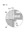
図11(a)は、封止樹脂348の成形後の状態を示す部分断面模式図であり、図11(b)は、被覆層601を設けずに、直接、半導体構造体302の表面に防水層602を設けた例(以下、比較例と記す)を示す部分断面模式図である。図12は、被覆層601および防水層602を設けた本実施の形態を示す部分断面模式図である。図11(a),(b)および図12は、それぞれ図4のA部に相当する部分の断面を模式的に示したものである。
図11(a)に示すように、封止樹脂348の成形後、封止樹脂348の熱収縮により、封止樹脂348と放熱フィン371の補強板371bとの境界面に極わずかな隙間Gが発生することがある。図11(b)に示すように、比較例では、被覆層601が形成されておらず、無電解銅めっきおよび無電解ニッケルめっきにより0.5μmの銅膜および20μmのニッケル膜とからなる防水層602が形成されている。しかしながら、比較例では、図11(b)に示すように隙間Gが十分に覆われず、放熱フィン371と封止樹脂348の境界面に沿って冷媒121が浸入し、半導体素子のリーク電流が増加して、正常に起動することができないという検証結果が得られた。仮に、隙間Gがめっき処理により形成された防水層602で覆われたとしても、異種部材の境界では応力が集中しやすいため、長期に亘って防水性を確保するのは困難である。
これに対して、本実施の形態では、図12に示すように、被覆層601で隙間(窪み)Gを埋めるようにして、被覆層601を覆い、被覆層601の表面に防水層602を形成しているため、冷媒121の浸入を防止して、長期に亘って正常に半導体モジュール300Aを動作させることができる。表面に存在する窪みS0,Gを埋める被覆層601を有しているので、比較例に比べて、防水層602の密着性が良くなり、信頼性が向上する効果がある。
(2)封止樹脂348の成形後、封止樹脂348の表面にはボイドによる窪みが発生する。本実施の形態では、被覆層601が、放熱フィン371と封止樹脂348との境界を含む、冷媒121の接触領域の全体に形成され、この被覆層601の表面に防水層602が形成されている。これにより、冷媒121の接触領域の全体で、封止樹脂348に対する冷媒121の直接的な接触を防止して、半導体モジュール300Aの長寿命化を図ることができる。
(3)被覆層601を有機化合物で形成したので、数μm~数百μmの窪みを覆うことができる。このため、放熱フィン371と封止樹脂348との境界に形成される隙間(窪み)や封止樹脂348の表面に形成される複数の窪みの幅や深さにばらつきがあっても、各窪みを被覆層601で覆うことができる。
(4)防水層602を金属で形成したので、冷媒121を遮断して、冷媒121が被覆層601に直接的に接触することを防止できる。
このように、被覆層601と防水層602の多層構造(積層構造)を採用することで、成形時に意図しない窪みS0,Gが形成されたとしても、冷媒121の浸入を遮断し、半導体チップやチップ部品等の素子周辺の吸水を防止し、吸水による半導体チップのリーク電流の増加や、複数の素子間のマイグレーションによる絶縁抵抗の低下等の絶縁性能の低下を防止することができる。
これは、複数種の異なる部材で構成される表面に被膜する際には、部材ごとに密着性が異なることから不均一になるのに対して、異種部材同士の境界に被覆層601を形成することで、その表面が単一材料となり、防水層602を均一に密着させることができるためである。これにより、長期に亘って正常に動作する信頼性の高い半導体モジュール300Aおよび電力変換装置200を提供することができる。
これは、複数種の異なる部材で構成される表面に被膜する際には、部材ごとに密着性が異なることから不均一になるのに対して、異種部材同士の境界に被覆層601を形成することで、その表面が単一材料となり、防水層602を均一に密着させることができるためである。これにより、長期に亘って正常に動作する信頼性の高い半導体モジュール300Aおよび電力変換装置200を提供することができる。
-第2の実施の形態-
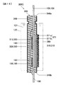
図13および図14を参照して第2の実施の形態に係る半導体モジュール300Bについて説明する。図13は、図3(a)と同様の図であり、第2の実施の形態に係る半導体モジュール300Bの斜視図である。図14は、図4と同様の図であり、第2の実施の形態に係る半導体モジュール300Bの断面模式図である。図中、第1の実施の形態と同一もしくは相当部分には同一符号を付し、説明を省略する。以下、第1の実施の形態との相違点について詳しく説明する。
図13および図14を参照して第2の実施の形態に係る半導体モジュール300Bについて説明する。図13は、図3(a)と同様の図であり、第2の実施の形態に係る半導体モジュール300Bの斜視図である。図14は、図4と同様の図であり、第2の実施の形態に係る半導体モジュール300Bの断面模式図である。図中、第1の実施の形態と同一もしくは相当部分には同一符号を付し、説明を省略する。以下、第1の実施の形態との相違点について詳しく説明する。
第1の実施の形態では、放熱フィン371が半導体モジュール300Aの一方の面にのみ設けられている例について説明したが、第2の実施の形態では、半導体モジュール300Bの両方の面に放熱フィン371が設けられている。
図14に示すように、第1導体板315および第3導体板320の外側面には絶縁性を有する絶縁板389が接合され、絶縁板389の外側面には補強板371bが接合され、トランスファーモールド成形の後、補強板371bの露出面にフィン板371aが接合される。絶縁板389は、絶縁性を有するセラミックスなどの無機化合物や絶縁性を有する樹脂などの有機化合物からなり、放熱フィン371と導体板315,320との間に配置されて、両者を絶縁する。絶縁板389の材質は、熱伝導率の高いものを選択することが好ましい。絶縁板389を樹脂で形成する場合、樹脂成分が完全に硬化する前の状態、すなわち粘着性を有する状態で導体板315,320、および、補強板371bに接続することが好ましい。なお、放熱フィン371を構成する補強板371bやフィン板371aが絶縁性を有する材料で形成される場合は、絶縁板389を省略することができる。
補強板371bおよびフィン板371aは、アルミニウム、銅、マグネシウムなど、封止樹脂348に用いられる材料に比べて熱伝導率の高い金属材料やアルミナなどのセラミックス材料からなる。補強板371bの材質は、フィン板371aの材質よりも剛性の高い材質を選択することが好適である。
第1導体板315または第3導体板320と、絶縁板389と、補強板371bと、フィン板371aとは、溶接、はんだ、摩擦攪拌接合などにより接合される。なお、フィン板371aの強度が十分な場合には、補強板371bを省略することができる。
このような第2の実施の形態によれば、第1の実施の形態と同様の作用効果を奏する。なお、第1の実施の形態に比べて、放熱フィン371の放熱面積が増えているため、第1の実施の形態よりも冷却性能を向上できる。
-第3の実施の形態-
図15を参照して第3の実施の形態に係る半導体モジュール300Cについて説明する。図15は、図4と同様の図であり、第3の実施の形態に係る半導体モジュール300Cの断面模式図である。図中、第1の実施の形態と同一もしくは相当部分には同一符号を付し、説明を省略する。以下、第1の実施の形態との相違点について詳しく説明する。
図15を参照して第3の実施の形態に係る半導体モジュール300Cについて説明する。図15は、図4と同様の図であり、第3の実施の形態に係る半導体モジュール300Cの断面模式図である。図中、第1の実施の形態と同一もしくは相当部分には同一符号を付し、説明を省略する。以下、第1の実施の形態との相違点について詳しく説明する。
第1の実施の形態では、各端子が一の端子面348aに配置されていたが、第3の実施の形態では、一の端子面348aの反対側の面(以下、他の端子面348b)にも端子が配置されている。第3の実施の形態では、一の端子面348aからは、図5に示される直流負極端子158、直流正極端子157および交流端子159、ゲート電極端子154,164、エミッタ電極端子155,165が延在し、他の端子面348bからは電流検出端子190が延在している。
第3の実施の形態では、図15に示すように、2つの端子面348a,348bが露出しているため、すなわち2つの端子面348a,348bには被覆層601および防水層602が形成されていないため、第1の実施の形態に比べて、被覆層601および防水層602が形成されない面積が増えている。第3の実施の形態では、2つの端子面348a,348bや端子を養生部材で覆い、塗布溶液により被覆層601を形成する。その後、防水層602を形成し、養生部材を取り外す。
このような第3の実施の形態によれば、第1の実施の形態と同様の作用効果を奏することができる。なお、第1の実施の形態よりも被覆層601および防水層602が形成される面積が少ないので、第1の実施の形態よりも重量およびコストを低減できる。
-第4の実施の形態-
図16を参照して第4の実施の形態に係る半導体モジュール300Dについて説明する。図16は、図4と同様の図であり、第4の実施の形態に係る半導体モジュール300Dの断面模式図である。図中、第1の実施の形態と同一もしくは相当部分には同一符号を付し、説明を省略する。以下、第1の実施の形態との相違点について詳しく説明する。
図16を参照して第4の実施の形態に係る半導体モジュール300Dについて説明する。図16は、図4と同様の図であり、第4の実施の形態に係る半導体モジュール300Dの断面模式図である。図中、第1の実施の形態と同一もしくは相当部分には同一符号を付し、説明を省略する。以下、第1の実施の形態との相違点について詳しく説明する。
第1の実施の形態では、半導体構造体302における冷媒121の接触領域の全体に被覆層601および防水層602が形成されていたが、第4の実施の形態では、放熱フィン371の周縁部を除き、放熱フィン371には被覆層601および防水層602が形成されていない。
第4の実施の形態では、被覆層形成工程において、放熱フィン371の表面を養生部材で覆った状態で塗布溶液に浸漬し、被覆層601を形成する。その後、防水層602を形成し、養生部材を取り外す。第4の実施の形態では、フィン板371aの周縁部、すなわち放熱フィン371と封止樹脂348の境界近傍における放熱フィン371には、被覆層601および防水層602が形成されている。
第4の実施の形態では、被覆層601および防水層602は、封止樹脂348における冷媒121の接触領域の全体に形成されるが、放熱フィン371には被覆層601および防水層602が形成されずに露出している。このため、第1の実施の形態と同様の作用効果に加え、放熱フィン371を直接冷媒に接触させて熱交換をすることができるので、放熱効果をより高めることができるという作用効果を奏する。また、第1の実施の形態よりも重量およびコストを低減できる。なお、第2の実施の形態や第3の実施の形態でも同様に、放熱フィン371を冷媒に接触させる構成を採用することができる。
次のような変形も本発明の範囲内であり、変形例の一つ、もしくは複数を上述の実施形態と組み合わせることも可能である。
(変形例1)
フィン板371a、補強板371bおよび絶縁板389の位置関係は、上述した実施の形態に限定されない。たとえば、図17(a)に示すように、補強板371bの外形をフィン板371aの外形よりも一回り大きくしてもよい。上述した実施の形態では、封止樹脂348と補強板371bの境界において、封止樹脂348、補強板371b、フィン板371aおよび被覆層601の4種類の異なる材料からなる4つの構成部材が交わる部分が存在していた(図4のA部拡大図参照)。これに対して、本変形例では、補強板371bの大きさをフィン板371aよりも大きくすることで、封止樹脂348と補強板371bの境界(B1部)において、封止樹脂348、補強板371bおよび被覆層601の3つの異種部材が交わる部分とすることができる。これにより4つの異種部材が交わる第1の実施の形態に比べて、交点の部分(B1部)における応力集中を緩和することができる。
(変形例2)
フィン板371a、補強板371bおよび絶縁板389の材料をそれぞれ異なるものとする場合に限定されない。たとえば、図17(b)に示すように、補強板371bとフィン板371aとを同じ材料で形成することで、封止樹脂348と補強板371bの境界(B1部)において、3つの異種部材が交わることになる。このため、4つの異種部材が交わる構造に比べ、応力集中を緩和することができる。なお、図17(c)に示すように、補強板371bを省略した場合も同様にB1部における応力集中を緩和することができる。
フィン板371a、補強板371bおよび絶縁板389の材料をそれぞれ異なるものとする場合に限定されない。たとえば、図17(b)に示すように、補強板371bとフィン板371aとを同じ材料で形成することで、封止樹脂348と補強板371bの境界(B1部)において、3つの異種部材が交わることになる。このため、4つの異種部材が交わる構造に比べ、応力集中を緩和することができる。なお、図17(c)に示すように、補強板371bを省略した場合も同様にB1部における応力集中を緩和することができる。
(変形例3)
上述した実施の形態では、ポリアミドイミドにより被覆層601を形成する例について説明したが、本発明はこれに限定されない。ポリアミドイミドに代えて、ポリイミド、ポリイミダゾール、フェノール樹脂、エポキシ樹脂、メラミン樹脂など、種々の熱硬化性樹脂により被覆層601を形成することができる。塗布溶液は、少なくとも溶剤と樹脂成分から構成されている。なお、無機フィラーを配合してもよい。なお、防水層602を金属で形成することを考慮し、耐薬品性や耐熱性に優れたものを選択することが好適である。
上述した実施の形態では、ポリアミドイミドにより被覆層601を形成する例について説明したが、本発明はこれに限定されない。ポリアミドイミドに代えて、ポリイミド、ポリイミダゾール、フェノール樹脂、エポキシ樹脂、メラミン樹脂など、種々の熱硬化性樹脂により被覆層601を形成することができる。塗布溶液は、少なくとも溶剤と樹脂成分から構成されている。なお、無機フィラーを配合してもよい。なお、防水層602を金属で形成することを考慮し、耐薬品性や耐熱性に優れたものを選択することが好適である。
たとえば、20重量%エポキシ樹脂で粘度が30Pa・sのメチルエチルケトン溶液を作製し、その後、この塗布溶液を用いて半導体構造体302の表面を塗膜する。150℃で1時間加熱硬化させることにより、被覆層601が形成される。
(変形例4)
上述した実施の形態では、塗布溶液に浸漬するディップ法により被覆層601を形成する例について説明したが、本発明はこれに限定されない。塗布溶液の塗布の方法は、浸漬に限定されず、スプレーや刷毛により塗布溶液を半導体構造体302に塗布して、被覆層601を形成してもよい。ディップ(浸漬)、スプレー、はけ塗り、あるいは、それらの組み合わせを用いることもできる。埋め込み性が不十分な場合には、重ね塗りを行うことで改善できる。
上述した実施の形態では、塗布溶液に浸漬するディップ法により被覆層601を形成する例について説明したが、本発明はこれに限定されない。塗布溶液の塗布の方法は、浸漬に限定されず、スプレーや刷毛により塗布溶液を半導体構造体302に塗布して、被覆層601を形成してもよい。ディップ(浸漬)、スプレー、はけ塗り、あるいは、それらの組み合わせを用いることもできる。埋め込み性が不十分な場合には、重ね塗りを行うことで改善できる。
(変形例5)
上述した実施の形態では、溶媒としてN-メチル-2-ピロリドンを採用した例について説明したが、本発明はこれに限定されない。室温で被覆層601を構成する樹脂との相溶性に優れる種々の溶媒を採用できる。たとえば、ジメチルスルホキシド、ジメチルホルムアミド、ジメチルアセトアミド、ジエチレングリコールジメチルエーテル、メチルエチルケトンなどの極性溶媒を用いることができる。
上述した実施の形態では、溶媒としてN-メチル-2-ピロリドンを採用した例について説明したが、本発明はこれに限定されない。室温で被覆層601を構成する樹脂との相溶性に優れる種々の溶媒を採用できる。たとえば、ジメチルスルホキシド、ジメチルホルムアミド、ジメチルアセトアミド、ジエチレングリコールジメチルエーテル、メチルエチルケトンなどの極性溶媒を用いることができる。
(変形例6)
上述した実施の形態では、有機化合物により被覆層601を形成する例について説明したが、本発明はこれに限定されない。無機化合物により被覆層601を形成してもよい。窪みS0,Gの幅や深さが小さい場合には、無機化合物により薄い被覆層601を形成することで、無駄なく被覆層601を形成することができる。たとえば、酸化ケイ素、酸化チタン、酸化ジルコニウム等の無機化合物により被覆層601を形成することができる。これらは、テトラエトキシシラン、テトラブトキシチタン、ジルコニウム(IV)プロポキシドなどを用いて、熱硬化させることにより酸化膜が形成される。熱硬化には使用した溶媒の沸点程度の加熱で十分なことから、ガラス被膜と異なり、半導体チップや封止樹脂348にダメージを与えることなく形成可能である。
上述した実施の形態では、有機化合物により被覆層601を形成する例について説明したが、本発明はこれに限定されない。無機化合物により被覆層601を形成してもよい。窪みS0,Gの幅や深さが小さい場合には、無機化合物により薄い被覆層601を形成することで、無駄なく被覆層601を形成することができる。たとえば、酸化ケイ素、酸化チタン、酸化ジルコニウム等の無機化合物により被覆層601を形成することができる。これらは、テトラエトキシシラン、テトラブトキシチタン、ジルコニウム(IV)プロポキシドなどを用いて、熱硬化させることにより酸化膜が形成される。熱硬化には使用した溶媒の沸点程度の加熱で十分なことから、ガラス被膜と異なり、半導体チップや封止樹脂348にダメージを与えることなく形成可能である。
溶媒は、無機化合物に応じて選択する。たとえば、エタノール、プロパノール、ブタノール、ヘキサノール、ペンタノールなどのアルコール系溶媒やトルエン、キシレン、シクロへキンサンなどを溶媒として選択できる。希釈溶液の安定性を得るために酢酸を加えてもよい。
無機化合物により被覆層601を形成する場合、塗布溶液に対する無機元素比率が2重量%を超えると、数秒から数時間で自己縮合が開始され、固形化するため、作業性が悪くなる。このため、全体の塗布溶液に対して無機元素比率は2重量%以下とすることが好ましい。全体の塗布溶液に対して無機元素比率が2重量%以下であれば、化学変化が起こらず、安定な塗布溶液として使用することができる。なお、無機化合物による被覆層形成方法としては、ディップ(浸漬)、スプレー、はけ塗り、あるいは、それらの組み合わせを用いることができる。埋め込み性が不十分な場合には、重ね塗りを行うことで改善できる。
無機化合物により被覆層601を形成する一例としては、1重量%テトラエトキシシランのエタノール溶液を作製し、その後、この塗布溶液をスプレーにて半導体構造体302に噴霧し塗膜する。100℃で1時間加熱硬化させることにより酸化ケイ素膜が形成される。この工程を2,3回程度繰り返し行うことで窪みS0,Gを埋めるように覆う被覆層601が形成される。
無機化合物により被覆層601を形成する他の一例としては、1重量%テトラブトキシチタンのトルエン溶液を作製し、その後、この塗布溶液に半導体構造体302を浸漬すること(ディップ法)によって塗膜する。浸漬塗膜後、80℃、120℃で各々1時間加熱することで硬化させ、酸化チタン膜を形成する。この工程を2,3回程度繰り返し行うことで窪みS0,Gを埋めるように覆う被覆層601が形成される。
(変形例7)
上述した実施の形態では、非金属により被覆層601を形成する例について説明したが、本発明はこれに限定されない。クロム、チタン、銅およびそれらの合金などの金属により被覆層601を形成してもよい。金属からなる被覆層(金属膜)は、スパッタ、蒸着、無電解めっき等によって形成することができる。金属膜は、窪みS0,Gを埋めるように覆う機能だけでなく、金属からなる防水層602との密着性を向上させる機能を有する。
上述した実施の形態では、非金属により被覆層601を形成する例について説明したが、本発明はこれに限定されない。クロム、チタン、銅およびそれらの合金などの金属により被覆層601を形成してもよい。金属からなる被覆層(金属膜)は、スパッタ、蒸着、無電解めっき等によって形成することができる。金属膜は、窪みS0,Gを埋めるように覆う機能だけでなく、金属からなる防水層602との密着性を向上させる機能を有する。
金属により被覆層601を形成する一例としては、スパッタ法により、下地膜として0.1μmのクロム膜を形成した後に、1μmの銅膜を形成した。スパッタは、たとえば、被覆層601を形成する半導体構造体302の各面ごとに行うことで、ターゲットとなる金属からの距離が一定となり、均一な金属膜を得ることができる。
(変形例8)
上述した実施の形態では、銅膜(下地膜)の上にニッケル膜を形成し、銅膜とニッケル膜とからなる防水層602を形成する例について説明したが、本発明はこれに限定されない。下地膜を形成せずに、無電解ニッケルめっきを施してニッケル膜のみで防水層602を形成してもよい。材料については、銅(Cu)やニッケル(Ni)に限定されず、錫(Sn)、亜鉛(Zn)や、銅、ニッケル、錫、亜鉛を含む合金(たとえば、ニッケルリン(Ni-P)合金、ニッケルボロン(Ni-B)合金、ニッケルリンボロン(Ni-P-B)多元合金)を用いることができる。ニッケルは耐食性に特に優れており、銅は熱伝導性に特に優れているため、用途に応じて選択することが好ましい。
上述した実施の形態では、銅膜(下地膜)の上にニッケル膜を形成し、銅膜とニッケル膜とからなる防水層602を形成する例について説明したが、本発明はこれに限定されない。下地膜を形成せずに、無電解ニッケルめっきを施してニッケル膜のみで防水層602を形成してもよい。材料については、銅(Cu)やニッケル(Ni)に限定されず、錫(Sn)、亜鉛(Zn)や、銅、ニッケル、錫、亜鉛を含む合金(たとえば、ニッケルリン(Ni-P)合金、ニッケルボロン(Ni-B)合金、ニッケルリンボロン(Ni-P-B)多元合金)を用いることができる。ニッケルは耐食性に特に優れており、銅は熱伝導性に特に優れているため、用途に応じて選択することが好ましい。
(変形例9)
上述した実施の形態では、無電解めっきにより防水層602を形成する例について説明したが、本発明はこれに限定されない。電気めっき、あるいは無電解めっきと電気めっきの組み合わせにより防水層602を形成してもよい。無電解めっきや電気めっきは、量産に適しているだけでなく、コールドスプレーや溶射と言った方法に比べて、半導体構造体302に与えるダメージが小さいためである。
上述した実施の形態では、無電解めっきにより防水層602を形成する例について説明したが、本発明はこれに限定されない。電気めっき、あるいは無電解めっきと電気めっきの組み合わせにより防水層602を形成してもよい。無電解めっきや電気めっきは、量産に適しているだけでなく、コールドスプレーや溶射と言った方法に比べて、半導体構造体302に与えるダメージが小さいためである。
(変形例10)
上述した実施の形態では、封止樹脂348における冷媒121の接触領域の全体に被覆層601および防水層602が形成されている例について説明したが、本発明はこれに限定されない。少なくとも、封止樹脂348と放熱フィン371との境界を覆うように被覆層601が設けられ、この被覆層601を覆うように防水層602を設ければよい。
上述した実施の形態では、封止樹脂348における冷媒121の接触領域の全体に被覆層601および防水層602が形成されている例について説明したが、本発明はこれに限定されない。少なくとも、封止樹脂348と放熱フィン371との境界を覆うように被覆層601が設けられ、この被覆層601を覆うように防水層602を設ければよい。
(変形例11)
上述した実施の形態では、放熱フィン371および絶縁板389が、導体板318,319,315,320の熱を伝える伝熱部材として構成されている例について説明したが、本発明はこれに限定されない。絶縁板389に代えてシート状の絶縁シートを設けてもよい。上述したように、放熱フィン371の補強板371bを、絶縁性を有する材料により形成し、絶縁板389を省略してもよい。放熱フィン371のフィン形状は円柱形状に限定されず、種々のフィン形状を採用できる。さらに、放熱フィン371に代えて、フィンを有していない平板状の放熱板を採用してもよい。
上述した実施の形態では、放熱フィン371および絶縁板389が、導体板318,319,315,320の熱を伝える伝熱部材として構成されている例について説明したが、本発明はこれに限定されない。絶縁板389に代えてシート状の絶縁シートを設けてもよい。上述したように、放熱フィン371の補強板371bを、絶縁性を有する材料により形成し、絶縁板389を省略してもよい。放熱フィン371のフィン形状は円柱形状に限定されず、種々のフィン形状を採用できる。さらに、放熱フィン371に代えて、フィンを有していない平板状の放熱板を採用してもよい。
(変形例12)
上述した実施の形態では、電子制御装置の一例として電力変換装置(インバータ)を挙げて説明したが、本発明はこれに限定されない。半導体モジュールを備える種々の電子制御装置に本発明を適用できる。
上述した実施の形態では、電子制御装置の一例として電力変換装置(インバータ)を挙げて説明したが、本発明はこれに限定されない。半導体モジュールを備える種々の電子制御装置に本発明を適用できる。
本発明の特徴を損なわない限り、本発明は上記実施の形態に限定されるものではなく、本発明の技術的思想の範囲内で考えられるその他の形態についても、本発明の範囲内に含まれる。
21 コネクタ、121 冷媒、122 ケース、136 バッテリ、138 直流コネクタ、140 インバータ回路、150 直列回路、153 コレクタ電極端子、154 ゲート電極端子、155 エミッタ電極端子、156 ダイオード、157 直流正極端子、158 直流負極端子、159 交流端子、160 金属接合材、163 コレクタ電極端子、165 エミッタ電極端子、166 ダイオード、169 中間電極、172 制御回路、174 ドライバ回路、180 電流センサ、188 交流端子、190 電流検出端子、200 電力変換装置、300A,300B,300C,300D 半導体モジュール、302 半導体構造体、315 第1導体板、318 第2導体板、319 第4導体板、320 第3導体板、329 中間電極、348 封止樹脂、348a,348b 端子面、371 放熱フィン、371a フィン板、371b 補強板、389 絶縁板、500 コンデンサモジュール、504 コンデンサ端子、506 コンデンサ端子、508 電源端子、509 電源端子、601 被覆層、602 防水層、802 交流バスバー、950 導体板組み、951 タイバー
Claims (12)
- 半導体素子と、前記半導体素子が接合された導体部材と、前記半導体素子に熱伝導可能に設けられた放熱部材と、前記放熱部材とは異なる材質からなり、前記放熱部材の一面を露出して前記半導体素子を封止する封止材とを備える半導体構造体と、
少なくとも冷媒の接触領域内における前記放熱部材と前記封止材との境界を覆う被覆層と、
前記被覆層とは異なる材質からなり、前記被覆層の表面に形成される防水層とを備える半導体モジュール。 - 請求項1に記載の半導体モジュールにおいて、
前記被覆層は、前記封止材における冷媒の接触領域の全体に形成されている半導体モジュール。 - 請求項1または2に記載の半導体モジュールにおいて、
前記被覆層は、有機化合物からなる半導体モジュール。 - 請求項1または2に記載の半導体モジュールにおいて、
前記被覆層は、無機化合物からなる半導体モジュール。 - 請求項1または2に記載の半導体モジュールにおいて、
前記被覆層は、金属からなる半導体モジュール。 - 請求項1または2に記載の半導体モジュールにおいて、
前記防水層は、厚みが500μm以下の金属膜である半導体モジュール。 - 請求項1または2に記載の半導体モジュールを備える電子制御装置。
- 半導体素子と、前記半導体素子が接合された導体部材と、前記半導体素子に熱伝導可能に設けられた放熱部材と、前記放熱部材とは異なる材質からなり、前記放熱部材の一面を露出して前記半導体素子を封止する封止材とを備える半導体構造体を準備し、
少なくとも冷媒の接触領域内における前記放熱部材と前記封止材との境界を覆う被覆層を形成し、
前記被覆層の表面に前記被覆層とは異なる材質からなる防水層を形成する半導体モジュールの製造方法。 - 請求項8に記載の半導体モジュールの製造方法において、
前記被覆層を形成する際、前記封止材における冷媒の接触領域の全体に前記被覆層を形成する半導体モジュールの製造方法。 - 請求項8または9に記載の半導体モジュールの製造方法において、
前記被覆層を形成する際、樹脂の含有量が5重量%以上100重量%以下の塗布溶液を塗布することで、前記被覆層を形成する半導体モジュールの製造方法。 - 請求項8または9に記載の半導体モジュールの製造方法において、
前記被覆層を形成する際、粘度が0.1Pa・s以上100Pa・s以下の塗布溶液を塗布することで、前記被覆層を形成する半導体モジュールの製造方法。 - 請求項8または9に記載の半導体モジュールの製造方法において、
前記被覆層を形成する際、無機元素比率が2重量%以下の塗布溶液を塗布することで、前記被覆層を形成する半導体モジュールの製造方法。
Applications Claiming Priority (2)
| Application Number | Priority Date | Filing Date | Title |
|---|---|---|---|
| JP2014-114992 | 2014-06-03 | ||
| JP2014114992A JP6344981B2 (ja) | 2014-06-03 | 2014-06-03 | 半導体モジュールの製造方法 |
Publications (1)
| Publication Number | Publication Date |
|---|---|
| WO2015186470A1 true WO2015186470A1 (ja) | 2015-12-10 |
Family
ID=54766548
Family Applications (1)
| Application Number | Title | Priority Date | Filing Date |
|---|---|---|---|
| PCT/JP2015/063406 Ceased WO2015186470A1 (ja) | 2014-06-03 | 2015-05-11 | 半導体モジュールおよび半導体モジュールの製造方法ならびに電子制御装置 |
Country Status (2)
| Country | Link |
|---|---|
| JP (1) | JP6344981B2 (ja) |
| WO (1) | WO2015186470A1 (ja) |
Cited By (1)
| Publication number | Priority date | Publication date | Assignee | Title |
|---|---|---|---|---|
| WO2022209083A1 (ja) * | 2021-03-29 | 2022-10-06 | 日立Astemo株式会社 | パワー半導体装置 |
Families Citing this family (4)
| Publication number | Priority date | Publication date | Assignee | Title |
|---|---|---|---|---|
| JP6643481B2 (ja) | 2016-07-27 | 2020-02-12 | 株式会社日立製作所 | 半導体モジュールおよび半導体モジュールの製造方法 |
| DE102016117843A1 (de) | 2016-09-21 | 2018-03-22 | Infineon Technologies Ag | Mit Kühlfluid gekühlte und eine Abschirmschicht umfassende Packung |
| WO2018135555A1 (ja) | 2017-01-18 | 2018-07-26 | 株式会社村田製作所 | モジュール |
| JP7278439B1 (ja) | 2022-02-08 | 2023-05-19 | 三菱電機株式会社 | 半導体装置及びそれを用いた電力変換装置 |
Citations (7)
| Publication number | Priority date | Publication date | Assignee | Title |
|---|---|---|---|---|
| JPS61166053A (ja) * | 1985-01-17 | 1986-07-26 | Nitto Electric Ind Co Ltd | 半導体装置の製法 |
| JPH0260150A (ja) * | 1988-08-26 | 1990-02-28 | Semiconductor Energy Lab Co Ltd | 電子装置およびその作製方法 |
| JP2004119667A (ja) * | 2002-09-26 | 2004-04-15 | Mitsubishi Electric Corp | 電力用半導体装置 |
| JP2006128260A (ja) * | 2004-10-27 | 2006-05-18 | Toyota Motor Corp | 半導体装置および冷却器付半導体装置 |
| JP2012191057A (ja) * | 2011-03-11 | 2012-10-04 | Mitsubishi Electric Corp | 電力用半導体装置 |
| JP2013105884A (ja) * | 2011-11-14 | 2013-05-30 | Denso Corp | 半導体モジュール |
| JP2014013931A (ja) * | 2013-09-12 | 2014-01-23 | Denso Corp | 半導体パッケージ |
Family Cites Families (2)
| Publication number | Priority date | Publication date | Assignee | Title |
|---|---|---|---|---|
| JP2007207873A (ja) * | 2006-01-31 | 2007-08-16 | Aisin Seiki Co Ltd | 電子装置 |
| JP2008270294A (ja) * | 2007-04-16 | 2008-11-06 | Sumitomo Electric Ind Ltd | ヒートシンク部材および半導体装置 |
-
2014
- 2014-06-03 JP JP2014114992A patent/JP6344981B2/ja not_active Expired - Fee Related
-
2015
- 2015-05-11 WO PCT/JP2015/063406 patent/WO2015186470A1/ja not_active Ceased
Patent Citations (7)
| Publication number | Priority date | Publication date | Assignee | Title |
|---|---|---|---|---|
| JPS61166053A (ja) * | 1985-01-17 | 1986-07-26 | Nitto Electric Ind Co Ltd | 半導体装置の製法 |
| JPH0260150A (ja) * | 1988-08-26 | 1990-02-28 | Semiconductor Energy Lab Co Ltd | 電子装置およびその作製方法 |
| JP2004119667A (ja) * | 2002-09-26 | 2004-04-15 | Mitsubishi Electric Corp | 電力用半導体装置 |
| JP2006128260A (ja) * | 2004-10-27 | 2006-05-18 | Toyota Motor Corp | 半導体装置および冷却器付半導体装置 |
| JP2012191057A (ja) * | 2011-03-11 | 2012-10-04 | Mitsubishi Electric Corp | 電力用半導体装置 |
| JP2013105884A (ja) * | 2011-11-14 | 2013-05-30 | Denso Corp | 半導体モジュール |
| JP2014013931A (ja) * | 2013-09-12 | 2014-01-23 | Denso Corp | 半導体パッケージ |
Cited By (3)
| Publication number | Priority date | Publication date | Assignee | Title |
|---|---|---|---|---|
| WO2022209083A1 (ja) * | 2021-03-29 | 2022-10-06 | 日立Astemo株式会社 | パワー半導体装置 |
| JP7587454B2 (ja) | 2021-03-29 | 2024-11-20 | 日立Astemo株式会社 | パワー半導体装置 |
| US12660617B2 (en) | 2021-03-29 | 2026-06-16 | Hitachi Astemo, Ltd. | Power semiconductor device |
Also Published As
| Publication number | Publication date |
|---|---|
| JP6344981B2 (ja) | 2018-06-20 |
| JP2015230913A (ja) | 2015-12-21 |
Similar Documents
| Publication | Publication Date | Title |
|---|---|---|
| JP6446280B2 (ja) | 電子装置 | |
| US9246408B2 (en) | Power conversion apparatus | |
| CN102414816B (zh) | 功率模块及电力转换装置 | |
| JP5651552B2 (ja) | 電力変換装置 | |
| US9999150B2 (en) | Electric power converter | |
| JP5663462B2 (ja) | パワー半導体モジュールおよびパワーモジュール | |
| CN103597729B (zh) | 功率模块和使用它的电力转换装置 | |
| US8847374B2 (en) | Power semiconductor module and manufacturing method thereof | |
| JP5591396B2 (ja) | 半導体モジュール、および半導体モジュールの製造方法 | |
| JP6344981B2 (ja) | 半導体モジュールの製造方法 | |
| US20160343636A1 (en) | Waterproof Electronic Device and Manufacturing Method Thereof | |
| JP5975789B2 (ja) | パワー半導体モジュール | |
| US20170309540A1 (en) | Electronic device and method of manufacturing the electronic device | |
| JP5948106B2 (ja) | パワー半導体モジュール及びそれを用いた電力変換装置 | |
| JP2015073436A (ja) | 電力変換装置 | |
| JP5687786B2 (ja) | 電力変換装置 | |
| JP2013122993A (ja) | 半導体装置 | |
| WO2022210616A1 (ja) | 半導体装置および半導体システム |
Legal Events
| Date | Code | Title | Description |
|---|---|---|---|
| 121 | Ep: the epo has been informed by wipo that ep was designated in this application |
Ref document number: 15803717 Country of ref document: EP Kind code of ref document: A1 |
|
| NENP | Non-entry into the national phase |
Ref country code: DE |
|
| 122 | Ep: pct application non-entry in european phase |
Ref document number: 15803717 Country of ref document: EP Kind code of ref document: A1 |