WO2015186294A1 - 車載画像処理装置 - Google Patents
車載画像処理装置 Download PDFInfo
- Publication number
- WO2015186294A1 WO2015186294A1 PCT/JP2015/002349 JP2015002349W WO2015186294A1 WO 2015186294 A1 WO2015186294 A1 WO 2015186294A1 JP 2015002349 W JP2015002349 W JP 2015002349W WO 2015186294 A1 WO2015186294 A1 WO 2015186294A1
- Authority
- WO
- WIPO (PCT)
- Prior art keywords
- parking frame
- detection unit
- straight lines
- probability
- parking
- Prior art date
- Legal status (The legal status is an assumption and is not a legal conclusion. Google has not performed a legal analysis and makes no representation as to the accuracy of the status listed.)
- Ceased
Links
Images






Classifications
-
- G—PHYSICS
- G06—COMPUTING OR CALCULATING; COUNTING
- G06V—IMAGE OR VIDEO RECOGNITION OR UNDERSTANDING
- G06V20/00—Scenes; Scene-specific elements
- G06V20/50—Context or environment of the image
- G06V20/56—Context or environment of the image exterior to a vehicle by using sensors mounted on the vehicle
- G06V20/58—Recognition of moving objects or obstacles, e.g. vehicles or pedestrians; Recognition of traffic objects, e.g. traffic signs, traffic lights or roads
- G06V20/586—Recognition of moving objects or obstacles, e.g. vehicles or pedestrians; Recognition of traffic objects, e.g. traffic signs, traffic lights or roads of parking space
Definitions
- This disclosure relates to an in-vehicle image processing device.
- an in-vehicle image processing device that detects a straight line by acquiring an image from an imaging device mounted on a vehicle and performing image processing on the image is known. And a vehicle-mounted image processing apparatus detects the parking frame which comprises a parking area from the detected straight line.
- the present disclosure has been made in view of the above points, and an object thereof is to provide an in-vehicle image processing device that can detect a parking frame more accurately.
- the inventors of the present invention have newly created the following disclosure, paying attention to the fact that the parking section is constituted by a line that is substantially orthogonal to the traveling route of the host vehicle.
- An in-vehicle image processing device that detects a parking frame that forms a parking section using an image acquired from an imaging device that captures the periphery of the host vehicle according to an aspect of the present disclosure includes an image acquisition unit that acquires an image from the imaging device; When a set of straight lines configured by a straight line detection unit that detects a plurality of straight lines from an image acquired by the image acquisition unit and two straight lines selected from the plurality of straight lines detected by the straight line detection unit satisfies a predetermined condition A parking frame candidate detection unit that detects the set of straight lines as a parking frame candidate, and a parking frame candidate in which the degree of orthogonality between the straight line forming the parking frame candidate and the travel route of the host vehicle is within a predetermined range. And a parking frame detector for detecting as a parking frame.
- FIG. 1 is a diagram illustrating a state in which an imaging device is attached to the host vehicle in the first embodiment of the present disclosure.
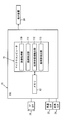
- FIG. 2 is a diagram for explaining the configuration of the in-vehicle image processing device in the first embodiment.
- FIG. 3 is a diagram for explaining how the in-vehicle image processing device detects the travel route of the host vehicle in the first embodiment.
- FIG. 4 is a diagram illustrating a state where the in-vehicle image processing device detects a parking frame in the first embodiment.
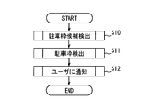
- FIG. 5 is a flowchart for explaining the flow of processing performed by the in-vehicle image processing device in the first embodiment.
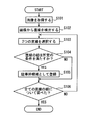
- FIG. 6 is a flowchart for explaining a flow in which the vehicle-mounted image processing device detects parking frame candidates in the first embodiment.
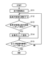
- FIG. 7 is a flowchart for explaining a flow in which the vehicle-mounted image processing device detects a parking frame in the first embodiment.
- FIG. 8 is a flowchart for explaining a flow in which the detected parking frame is notified to the user in the first embodiment.
- FIG. 9 is a diagram illustrating a state in which the vehicle-mounted image processing device detects a parking frame in the second embodiment of the present disclosure.
- FIG. 10 is a diagram illustrating a surrounding environment of the host vehicle when the in-vehicle image processing device detects a parking frame at the current time in the third embodiment of the present disclosure.
- FIG. 10 is a diagram illustrating a surrounding environment of the host vehicle when the in-vehicle image processing device detects a parking frame at the current time in the third embodiment of the present disclosure.
- FIG. 11 is a diagram illustrating a state in which the vehicle-mounted image processing device detects a parking frame at a past time in the third embodiment.
- FIG. 12 is a diagram illustrating a state where the in-vehicle image processing device detects a parking frame at the current time in the third embodiment.
- FIG. 13 is a diagram illustrating a relationship between the width between straight lines and the probability of a parking frame in the fourth embodiment of the present disclosure;
- FIG. 14 is a diagram showing the relationship between the degree of parallelism between straight lines and the probability of parking frame in the fourth embodiment.
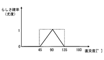
- FIG. 15 is a diagram illustrating a relationship between the degree of orthogonality and the probability of a parking frame in the fourth embodiment.
- a rear camera 21 that is an imaging device in the present embodiment is installed at the rear of the host vehicle 1. Moreover, the rear camera 21 is installed in the center part of the vehicle left-right direction.
- the in-vehicle image processing apparatus in the present embodiment is an ECU 10.
- the ECU 10 is connected to the rear camera 21, the vehicle speed sensor 23, the rudder angle sensor 24, and the display device 30.
- a CCD camera is used as the rear camera 21 to photograph the scenery behind the host vehicle 1.
- the vehicle speed sensor 23 is a sensor that detects the vehicle speed of the host vehicle 1.
- the steering angle sensor 24 is a sensor that detects the steering angle of the front wheels of the host vehicle 1.
- the display device 30 has a display such as a liquid crystal display and a control unit. Therefore, the control unit receives an image signal from the ECU 10 and displays an image corresponding to the received image signal on the display.
- the ECU 10 includes a microcomputer 11 and a memory 12.
- the ECU 10 acquires various types of information from the rear camera 21, the vehicle speed sensor 23, and the rudder angle sensor 24. And ECU10 performs arithmetic processing based on the acquired information. Details of the processing will be described later.
- the ECU 10 outputs an image signal to the display device 30. Then, the display device 30 displays an image based on the image signal received from the ECU 10.
- the memory 12 is connected to the microcomputer 11.
- the memory 12 is composed of a non-volatile memory or the like, and can store a result of processing calculated by the microcomputer 11.
- the parking frame storage unit in the present embodiment corresponds to the memory 12.
- the microcomputer 11 includes a CPU, a RAM, a ROM, and the like.
- the CPU performs various arithmetic processes based on programs stored in the RAM and ROM.
- the microcomputer 11 serves as the image acquisition unit 110, the straight line detection unit 111, the parking frame candidate detection unit 112, and the parking frame detection unit 113.
- the image acquisition unit 110 acquires images from the rear camera 21 at predetermined time intervals.
- the predetermined time interval can be set as appropriate. Further, the image acquisition unit 110 converts the acquired image into bird's-eye coordinates viewed from the bird's viewpoint, and generates a bird's-eye image.
- the value ⁇ of the Hough transform equation corresponds to the angle formed by the straight line passing through the position coordinates (x, y) with respect to the x axis, and the value ⁇ is from the origin to the straight line passing through the position coordinates (x, y). Corresponds to the length of the perpendicular. A straight line is detected based on ( ⁇ , ⁇ ).
- the parking frame candidate detection unit 112 selects any two straight lines from the plurality of straight lines acquired by the straight line detection unit 111. When the set of straight lines constituted by the two straight lines satisfies a predetermined condition, the parking frame candidate detection unit 112 detects the set of straight lines as a parking frame candidate.
- the predetermined condition in the present embodiment is whether or not the degree of parallelism between the angles formed by the two straight lines in the set of straight lines belongs to a predetermined range.
- a specific value in a predetermined range of the degree of parallelism is an angle of 0 ° to 45 ° or 135 ° to 180 °.
- the predetermined condition is whether or not the width between the straight lines in the set of straight lines is within a predetermined range.
- the specific width range is from 1.8 m to 3.0 m.
- the parking frame candidate detection part 112 determines whether the said predetermined conditions are satisfy
- the parking frame detection unit 113 detects a parking frame from the parking frame candidates detected by the parking frame candidate detection unit 112. Specifically, the parking frame detection unit 113 selects an arbitrary parking frame candidate from the parking frame candidates detected by the parking frame candidate detection unit 112. And it is detected whether the orthogonality of the angle which the straight line which comprises the parking frame candidate detection part 112 and the driving
- the parking area for parking the vehicle is often located on the side of the travel route of the host vehicle 1. And the parking area for one vehicle in the parking area is often divided as a parking frame by two straight lines that are substantially orthogonal to the traveling route of the vehicle.
- the ECU 10 in the present embodiment detects the parking frame more accurately in order to determine whether or not the orthogonality of the angle formed by the travel route of the host vehicle 1 and the straight line of the parking frame constituting the parking section belongs to a predetermined range. I can do it.
- the parking frame detection unit 113 detects the vehicle speed of the host vehicle 1 at a certain timing T from the vehicle speed sensor 23. In addition, the parking frame detection unit 113 detects the steering angle of the host vehicle 1 at the time T from the steering angle sensor 24. The time T-1 that is the timing when the parking frame detection unit 113 performed the previous parking frame is already known. Therefore, the parking frame detection unit 113 can detect a travel route including the traveling direction and the amount of movement of the host vehicle 1 between a certain time T-1 and a certain time T. Then, what has a predetermined width in a direction orthogonal to the travel route becomes the travel route of the host vehicle 1 at the interval ⁇ T. This runway can be superimposed on an image acquired by the image acquisition unit 110 at time T, and an example thereof is shown in FIG.
- FIG. 3 shows an image acquired by the image acquisition unit 110 at a certain time T.
- the runway 70 indicates the runway of the host vehicle 1 between time T-1 and time T.
- a runway 71 indicates a runway of the host vehicle 1 between time T-2 and time T-1.
- a runway 72 indicates the runway of the host vehicle 1 between time T-3 and time T-2.
- a travel route 701 indicates the traveling direction and the amount of movement of the host vehicle 1 between time T-1 and time T.
- the predetermined width 702 is orthogonal to the travel route 701 and has a predetermined width.
- the travel route 711 indicates the traveling direction and the amount of movement of the host vehicle 1 between time T-2 and time T-1.
- the predetermined width 712 is orthogonal to the travel route 711 and has a predetermined width.
- the travel route 721 indicates the traveling direction and the amount of movement of the host vehicle 1 between time T-3 and time T-2.
- the predetermined width 722 is orthogonal to the travel route 721 and has a predetermined width.
- FIG. 4 shows a bird's-eye view image generated by the image acquisition unit 110 using an image taken by the rear camera 21 at time T, which is a certain timing.
- an arrow 40 exists in the bird's-eye view image.
- a crosswalk 50 exists in the bird's-eye view image.
- the bird's eye image includes a parking section 60 and a parking section 61. From these, the ECU 10 detects the parking frames constituting the parking section 60 and the parking section 61.
- the bird's-eye view image includes information on the travel path 70 and the travel path 701 of the host vehicle 1 between time T-1 and time T.
- information on the travel path 71 and the travel path 711 of the host vehicle 1 between the time T-2 and the time T-1 which are past timings is included.
- information on the traveling path 72 and the traveling path 721 of the host vehicle 1 between the time T-3 and the time T-2, which are past timings is included.
- the straight line detection unit 111 detects a straight line from the generated bird's-eye view image using the method described above. Then, the straight line detection unit 111 detects a straight line 40 a and a straight line 40 b that are straight lines constituting the arrow 40. Further, the straight line detection unit 111 detects a straight line 50 a and a straight line 50 b that are straight lines constituting the pedestrian crossing 50. Further, the straight line detection unit 111 detects a straight line 60 a and a straight line 60 b that are straight lines constituting the parking section 60. Further, the straight line detection unit 111 detects the straight lines 61 a and 61 b constituting the parking section 61. The straight line detection unit 111 also detects other straight lines from the image, but is omitted for simplification of description. Therefore, the straight line detection unit 111 detects eight straight lines from the image.
- the width between the straight lines 60a and 60b is 2.5 m.
- the width between the straight lines 61a and 61b is 2.5 m.
- the width between the straight lines 50a and 50b is 2.0 m.
- the width between the straight line 40a and the straight line 40b is 2.0 m.
- the parking frame candidate detection unit 112 detects a parking frame candidate will be described as an example in which the straight line 60a and the straight line 60b are a set of straight lines.
- the parking frame candidate detection unit 112 determines the degree of parallelism between the straight line 60a and the straight line 60b. Then, the parking frame candidate detection unit 112 determines whether or not the degree of parallelism of the angles formed by the straight line 60a and the straight line 60b belongs to a predetermined range. Then, the degree of parallelism of the angle formed by the straight line 60a and the straight line 60b belongs to a predetermined range.
- the parking frame candidate detection unit 112 determines whether or not the width between the straight line 60a and the straight line 60b belongs to a predetermined range. Then, since this width is 2.5 m, the parking frame candidate detection unit 112 determines that the width between the straight lines 60a and 60b satisfies a predetermined range. As described above, since the predetermined condition is satisfied, the parking frame candidate detection unit 112 detects a straight line set of the straight line 60a and the straight line 60b as a parking frame candidate.
- the parking frame candidate detection unit 112 determines the degree of parallelism between the straight line 40a and the straight line 60a. Then, the angle formed by the straight line 40a and the straight line 60a is substantially orthogonal, and the degree of parallelism does not belong within a predetermined range. Therefore, the set of the straight line 40a and the straight line 60a is not detected as a parking frame candidate.
- the first is a set of straight lines 40a and 40b.
- the second is a set of straight lines 60a and 60b.
- the third is a set of straight lines 61a and 61b.
- the fourth is a set of straight lines 50a and 50b.
- the parking frame detection unit 113 determines whether a parking frame candidate configured by a straight line 60a and a straight line 60b is a parking frame that constitutes a parking section.
- the parking frame detection unit 113 detects an angle formed by the travel route 701 of the host vehicle 1 and the straight line 60a. At this time, the formed angle is approximately 90 °, and the orthogonality of the formed angle belongs to a predetermined range of 45 ° to 135 °. Therefore, the parking frame detection part 113 detects the parking frame candidate comprised by the straight line 60a and the straight line 60b as a parking frame.
- the parking frame detection unit 113 detects whether the parking frame candidate constituted by the straight line 40a and the straight line 40b is a parking frame.
- the parking frame detection unit 113 detects an angle formed by the travel route 701 and the straight line 40a. Then, the angle formed is almost 0 ° and does not satisfy the predetermined range of 45 ° to 135 °. Therefore, the parking frame detection unit 113 does not detect a parking frame candidate constituted by the straight line 40a and the straight line 40b as a parking frame.
- the parking frame detection unit 113 detects whether the parking frame candidate configured by the straight line 50a and the straight line 50b is a parking frame.
- the parking frame detection unit 113 detects an angle formed by the travel route 701 and the straight line 50a. Then, the angle formed is almost 0 ° and does not satisfy the predetermined range of 45 ° to 135 °. Therefore, the parking frame detection unit 113 does not detect a parking frame candidate constituted by the straight line 50a and the straight line 50b as a parking frame.
- the ECU 10 determines whether or not the degree of orthogonality between the straight line constituting the detected parking frame candidate and the travel route 701 of the host vehicle 1 is within a predetermined range. . Therefore, it is possible to prevent erroneous detection of the arrow 40 or the pedestrian crossing 50 as a parking frame.
- the detection of the parking frame based on the travel route 711 and the travel route 721 has already been performed at a past timing. That is, the parking frame on the bird's-eye view image generated by the image acquisition unit 110 at time T-1 is detected based on whether or not the orthogonality of the angle formed by the travel route 711 and the parking frame candidate is within a predetermined range. The The parking frame on the bird's-eye view image generated by the image acquisition unit 110 at time T-2 is detected based on whether or not the orthogonality of the angle formed by the travel route 721 and the parking frame candidate is within a predetermined range. The
- step S10 the ECU 10 detects a parking frame candidate.
- step S11 the ECU 10 detects a parking frame from the detected parking frame candidates.
- step S12 the ECU 10 notifies the user of the detected parking frame.
- FIG. 6 shows a specific processing flow in which the ECU 10 detects parking frame candidates.
- the image acquisition unit 110 acquires an image from the rear camera 21.
- the image acquisition unit 110 generates a bird's-eye image that is an image obtained by viewing the acquired image from the viewpoint of the bird. Thereafter, the process proceeds to step S102.
- step S102 the straight line detection unit 111 detects a straight line from the generated bird's-eye view image by the method described above.
- the detected straight line is stored in the memory 12. This step is performed until all straight lines are detected on the bird's-eye view image. Thereafter, the process proceeds to step S103.
- step S103 the parking frame candidate detection unit 112 selects any two straight lines from the straight lines detected by the straight line detection unit 111 and sets them as a set of straight lines. Thereafter, the process proceeds to step S104.
- step S104 the parking frame candidate detection unit 112 detects whether the set of straight lines satisfies a predetermined condition. Specifically, the parking frame candidate detection unit 112 determines whether or not the distance between the straight lines in the set belongs to a range of 1.8 m to 3.0 m. In addition, the parking frame candidate detection unit 112 determines whether the degree of parallelism between the straight lines of the set of straight lines belongs to a predetermined range of 0 ° to 45 ° or 135 ° to 180 °. If the set of straight lines satisfies a predetermined condition, the process proceeds to step S105, and if not, the process proceeds to step S106.
- step S105 the parking frame candidate detection unit 112 writes the selected straight line set in the memory 12 as a parking frame candidate. Then, it progresses to step S106.
- step S106 the parking frame candidate detection part 112 detects whether it checked whether it was a parking frame candidate about all the combinations of the straight line memorize
- FIG. 7 shows a specific processing flow in which the ECU 10 detects a parking frame from the detected parking frame candidates.
- the parking frame detection unit 113 detects the travel route 701 of the host vehicle 1 by the method described above. Thereafter, the process proceeds to step S112.
- step S ⁇ b> 112 the parking frame detection unit 113 selects an arbitrary parking frame candidate stored in the memory 12. Thereafter, the process proceeds to step S113.
- step S113 the parking frame detection unit 113 determines that the orthogonality between the angles formed by at least one of the straight lines constituting the parking frame candidate and the travel route 701 of the host vehicle 1 is within a predetermined range. Determine if it belongs. If it belongs to the predetermined range, the process proceeds to step S114. Otherwise, the process proceeds to step S115.
- step S114 the parking frame detection unit 113 writes the selected parking frame candidate in the memory 12 as a parking frame. Further, the parking frame detection unit 113 writes the time when the parking frame is detected in the memory 12. Thereafter, the process proceeds to step S115.
- step S115 the parking frame detection unit 113 determines whether or not the parking frame detection processing has been performed on all the parking frame candidates stored in the memory 12. A process is complete
- FIG. 8 is a flowchart showing how the parking frame detected by the parking frame detection unit 113 is notified to the user.
- step S121 the ECU 10 acquires a parking frame from the memory 12. And the image which shows the surrounding image of the own vehicle 1 is produced
- step S122 the user selects one parking frame among the parking frames highlighted in the image.
- the ECU 10 receives information on the parking frame selected by the user from the display device 30. Thereafter, the process proceeds to step S123.
- step S123 the ECU 10 generates an image in which only the parking frame selected by the user is highlighted, and transmits the image to the display device 30. Then, the display device 30 displays an image in which only the parking frame selected by the user is highlighted. Thereafter, the process ends.
- the ECU 10 in the present embodiment is an ECU 10 that detects a parking frame that forms a parking section using an image acquired from a rear camera 21 that captures the periphery of the host vehicle 1.
- the ECU 10 includes an image acquisition unit 110 that acquires an image from the rear camera 21.
- the ECU 10 includes a straight line detection unit 111 that detects a straight line from the image acquired by the image acquisition unit 110.
- the ECU 10 detects the set of straight lines as a parking frame candidate.
- a candidate detection unit 112 is provided.
- the ECU 10 includes a parking frame detection unit 113 that detects, as a parking frame, a parking frame candidate in which the degree of orthogonality between the straight line forming the parking frame candidate and the travel route 701 of the host vehicle 1 is within a predetermined range. I have.
- the parking frame which comprises the parking area with high possibility of orthogonally crossing with respect to the traveling route 701 of the own vehicle 1 can be detected more accurately.
- the parking frame detection part 113 is detecting the parking frame based on whether the orthogonality of the angle
- the parking frame detection unit 113 is positioned on the past or current traveling path of the host vehicle 1 even if the parking frame candidate has an orthogonality with respect to the traveling route of the host vehicle 1 within a predetermined range. A parking frame candidate that is present is prohibited from being detected as a parking frame.
- ECU10 in this embodiment is the same as that of 1st Embodiment, description is abbreviate
- FIG. 9 shows a bird's-eye view image generated by the image acquisition unit 110 according to the present embodiment at a certain timing time T.
- the difference from the first embodiment is that a straight line 501 and a straight line 502 exist in the longitudinal direction of the pedestrian crossing 50.
- the width of the straight lines 501 and 502 is 2.5 m.
- the ECU 10 in the present embodiment performs the following processing.
- the straight line detection unit 111 detects a straight line 501 and a straight line 502.
- the parking frame candidate detection part 112 detects the group of the straight line comprised by the straight line 501 and the straight line 502 as a parking frame candidate.
- the parking frame detection unit 113 determines whether or not the orthogonality of the angle formed by the parking frame candidate configured by the straight line 501 and the straight line 502 and the travel route 701 of the host vehicle 1 belongs to a predetermined range. Determine.
- the parking frame detection unit 113 determines whether or not the orthogonality of the angle formed by the straight line 501 and the travel route 701 of the host vehicle 1 belongs to 45 ° to 135 °. Then, since the formed angle is 90 °, it belongs to a predetermined range. Therefore, at this time, the parking frame detection unit 113 may detect a parking frame candidate constituted by the straight line 501 and the straight line 502 as a parking frame.
- the parking frame detection unit 113 of the present embodiment further detects whether or not the straight line 501 is located on the past or current runway of the host vehicle 1. That is, the parking frame detection unit 113 determines whether the straight line 501 is located on the runway 70, the runway 71, or the runway 72. When the straight line 501 is located on any one of the roads, the parking frame detection unit 113 prohibits detection of a parking frame candidate configured by the straight line 501 and the straight line 502 as a parking frame. In this case, the straight line 501 is located on the runway 72. Therefore, the parking frame detection unit 113 prohibits detection of a parking frame candidate configured by the straight line 501 and the straight line 502 as a parking frame.
- the parking frame detection unit 113 in the present embodiment prohibits detection of a parking frame candidate positioned on the traveling path of the host vehicle 1 as a parking frame.
- parking frame candidates that are substantially orthogonal to the travel route of the host vehicle 1 may appear on the travel route of the host vehicle 1.
- the parking frame which comprises a parking area will appear on the runway of the own vehicle 1.
- the ECU 10 of the present embodiment erroneously detects such a parking frame candidate as a parking frame. Can be prevented.
- Parking frame detection unit 113 prohibits detection of parking frame candidates located on a running road having a predetermined width with respect to the travel route as parking frames among the parking frame candidates.
- the parking section rarely appears on the track of the vehicle 1. Even if a parking frame candidate formed by an angle formed with the traveling route of the host vehicle 1 is detected on the traveling path of the host vehicle 1, the ECU 10 according to the present embodiment uses the parking frame candidate as a parking frame due to the above characteristic configuration. It is possible to prevent erroneous detection.
- the ECU 10 When detecting the parking frame at a certain timing, the ECU 10 according to the third embodiment refers to the parking frame detected at a timing earlier than the certain timing. And when the parking frame candidate currently existing on the image and the parking frame detected in the past acquired from the memory 12 correspond, the parking frame candidate is detected as a parking frame.
- Whether or not the current parking frame candidate corresponds to the parking frame acquired from the memory 12 is detected by performing the following process.
- the parking frame detection unit 113 acquires the parking frame from the memory 12 and the position coordinates on the image when detected in the past. And the driving
- the parking frame detection unit 113 detects the parking frame candidate as a parking frame.
- the own vehicle 1 indicated by the broken line in FIG. 10 indicates the own vehicle 1 at time T-1.
- a solid vehicle 1 represents the vehicle 1 at time T.
- the own vehicle 1 travels like a travel route 701 between time T-1 and time T.
- FIG. 11 shows a bird's-eye view image generated by the image acquisition unit 110 at time T-1.
- FIG. 12 shows a bird's-eye view image generated by the image acquisition unit 110 at time T.
- the parking frame detection unit 113 detects a pair of a straight line 61a and a straight line 61b as a parking frame.
- the parking frame is stored in the memory 12.
- the parking frame candidate detection unit 112 detects a pair of the straight line 61a and the straight line 61b as a parking frame candidate. And the parking frame detection part 113 determines whether the parking frame candidate is a parking frame. Then, since the orthogonality between the parking frame candidate and the current travel route 701 of the host vehicle 1 does not belong to a predetermined range, the parking frame detection unit 113 does not detect the parking frame candidate as a parking frame.
- the parking frame detection unit 113 of the present embodiment further performs the following processing.
- the parking frame detection unit 113 detects a parking frame stored in the memory 12. That is, the parking frame detection unit 113 detects a pair of the straight line 61a and the straight line 61b.
- the parking frame detection unit 113 detects a travel route from the time T-1 when the pair of the straight line 61a and the straight line 61b is detected as a parking frame to the current time T. That is, in this case, the travel route 701.
- the parking frame detection unit 113 specifies the position coordinates where the current parking frame should exist based on the position coordinates where the parking frame was detected and the travel route 701 at the past time T-1.
- the parking frame detection part 113 detects the parking frame candidate which corresponds to the position coordinate where the parking frame specified by said method should exist among the parking frame candidates detected at the present time T as a parking frame. To do. That is, the pair of straight lines 61a and 61b detected as a parking frame at time T-1 is also detected as a parking frame at time T.
- the parking frame detection unit 113 does not satisfy the predetermined range of the orthogonality between the parking frame candidate and the current travel route for the parking frame candidate once detected as a parking frame in the past. However, it can be detected as a parking frame.
- the travel route is a travel route on which the host vehicle has traveled from the timing when the parking frame detection unit 113 previously detected the parking frame to the present, and the ECU 10 detects the parking frame detected by the parking frame detection unit 113 in the past.
- a memory 12 for storing is provided.
- the parking frame detection unit 113 detects a parking frame candidate corresponding to the parking frame stored in the memory 12 as a parking frame in addition to the parking frame candidate whose orthogonality is within a predetermined range.
- the ECU 10 in this embodiment can detect a parking frame candidate once detected as a parking frame as a parking frame even if the orthogonality of the angle formed with respect to the travel route does not belong within a predetermined range thereafter.
- a straight line set that satisfies a predetermined width and whose parallel degree falls within a predetermined range is detected as a parking frame candidate. And among the parking frame candidates, all the ones in which the orthogonality between at least one straight line and the running road belong within a predetermined range were treated as the same parking frame.
- a probability of a parking frame is set in the detected parking frame.
- probabilities are set for each parameter.
- FIG. 13 shows the relationship between the width of straight lines of the above-mentioned straight line set and the probability of parking frame.
- the probability of the parking frame is set to 1.
- the probability of a parking frame is set to 0 for 1.5 m or less and 3.5 m or more.
- FIG. 14 shows the relationship between the degree of parallelism between the straight lines of the set of straight lines and the probability of parking frame.
- the probability B of the parking frame is 0.
- FIG. 15 shows the relationship between the degree of orthogonality between at least one straight line of the set of straight lines and the travel route 701 of the host vehicle 1 and the probability of a parking frame.
- the probabilities A, B, and C are integrated based on the following calculation formula, and the final parking frame-like integration probability E is detected.
- the probability integration formula that integrates the two probabilities is shown below.
- the probability integration arithmetic expression is similarly applied to the integration probability D and the probability C of orthogonality, and the integration probability of D and C is E
- This integration probability E is the integration probability of A, B, and C.
- the parking frame detection unit 113 can determine which of the parking frame candidates is more likely to be a parking frame, and use the calculated probability of parking frame, It can be determined whether the probability of likelihood exceeds a threshold value. For example, the parking frame detection unit 113 can detect a parking frame candidate that is more likely to be a parking frame among those having a parking frame likelihood of 50% or more.
- the parking frame detection unit 113 reduces the probability of the final parking frame as the parking frame probability is multiplied. That is, it can be determined only whether the parking frame candidates are more likely to be parking frames.
- the frame width between the straight lines is 2.3 m
- the degree of parallelism is 0 °
- the predetermined condition is that the length of the width between the straight lines belongs to a predetermined range, and the degree of parallelism of the angles formed by the straight lines belongs to the predetermined range.
- the parking frame detection part 113 is set based on the probability of the parking frame set based on the length of the width, the probability of the parking frame set based on the degree of parallelism, and the orthogonality.
- a parking frame is detected based on the probability that the probability of the parking frame is integrated.
- the ECU 10 of the present embodiment sets a probability indicating the possibility of the parking frame for the parking frame to be detected. For this reason, ECU10 in this embodiment can detect the parking frame with higher possibility of being the parking frame which comprises a parking area.
- the determination of the degree of orthogonality with the parking frame candidate is performed only for the current travel route, but a comparison with a past travel route may also be performed. Specifically, in the first embodiment, it is determined whether or not the orthogonality of the angle between the parking frame candidate and the travel route 711 in the image acquired by the image acquisition unit 110 at time T belongs to a predetermined range. It may be. Furthermore, you may make it determine whether the orthogonality of the angle
- the ECU 10 detects the parking frame based on the orthogonality between the traveling route and the parking frame candidate in both the straight traveling route and the traveling route that changes the rudder angle. It was.
- the present disclosure is not limited to this, and the parking frame is detected based on the orthogonality between the travel route and the parking frame candidate when the host vehicle 1 is traveling straight, and the host vehicle 1 is not traveling straight.
- the parking frame may not be detected based on the travel route. Most of the situations where the parking frame needs to be searched are when the host vehicle 1 is traveling straight. On the other hand, in a state where the steering angle of the host vehicle 1 is turned off, there is almost no situation where it is necessary to search for a parking frame.
- the straight line of the parking frame candidate whose orthogonality satisfies a predetermined range with respect to the travel route in a state where the steering angle of the host vehicle 1 is turned off is highly likely not to be a parking frame forming a parking section. . Therefore, with the above configuration, it is possible to prevent the ECU 10 from erroneously detecting the parking frame when the steering angle of the host vehicle 1 is turned off.
- the degree of parallelism between the straight lines and the width between the straight lines are used as the predetermined conditions when the parking frame candidate is detected.
- the present invention is not limited to this.
- only one of the degree of parallelism between the straight lines or the width between the straight lines may be adopted to detect the parking frame candidate.
- the degree of coincidence between two straight lines may be compared.
- parameters relating to the degree of coincidence between straight lines include color, brightness, length, thickness, shape, and contrast. At least one of the above parameters may be adopted.
- the parking frame-likeness as shown in the fourth embodiment is set, and in addition to the parking frame-likeness of the width, parallelism and orthogonality between the straight lines, the parking of each parameter is set.
- the final likelihood of parking frame may be calculated based on the likelihood of frame.
- the predetermined condition is that the brightness of the straight lines is the same, the contrast is the same, the length is the same, the thickness is the same, the colors are the same, and the widths of the straight lines are in a predetermined range. Satisfy at least one of the continuous appearance of a set of straight lines belonging to the inside.
- the parking frame detection unit is a parking frame set based on a probability of a parking frame set based on the degree of coincidence of brightness, a probability of a parking frame set based on a degree of coincidence of contrast, and a degree of coincidence of length. Probability of frameness, probability of parking frame that is set based on matching degree of thickness, probability of parking frame that is set based on matching degree of color, and the length of the width between straight lines are within a predetermined range A parking frame may be detected based on a probability obtained by integrating at least one probability of a parking frame among the probability of a parking frame set based on the degree to which a set of straight lines belonging to the inside is continuous.
- the parking frame may be detected in consideration of whether a plurality of straight line sets having the same width and color between the straight lines appear continuously in a predetermined direction. Furthermore, it may be possible to set the likelihood of a parking frame and use it for the final calculation of the likelihood of a parking frame as to whether or not straight lines having the same width and color are continuous.
- the parking frame detection unit 113 performs a process of determining whether the parking frame candidate is a pedestrian crossing based on the width or parallelism of the straight lines, and the parking frame candidate determined to be a pedestrian crossing is a parking frame. You may make it not detect.
- the parking frame detection part 113 performs the process which determines whether a parking frame candidate is a character based on the width
- the method for detecting the travel route of the host vehicle 1 is not limited to the above embodiment.
- the position of the host vehicle 1 at each timing may be specified based on GPS, and the travel route may be obtained using the difference.
- the travel route of the host vehicle 1 may be calculated based on the coordinate change amount of an arbitrary edge point between each timing.
- the predetermined range of the orthogonality is 45 ° to 135 °.
- the present invention is not limited to this and can be set as appropriate.
- the angle may be 80 ° to 120 °.
- a predetermined range of the degree of parallelism and the length of the width can be set as appropriate.
- the travel route includes both the movement direction and the movement amount, but may include information only on the movement direction.
- the parking frame detection unit 113 in the above embodiment detects the parking frame every time the image acquisition unit 110 generates a bird's-eye view image. However, after the image acquisition unit 110 generates the bird's-eye image a predetermined number of times, parking is performed. A frame may be detected.
- the parking frame storage unit is the memory 12 provided in the ECU 10, but may be a storage medium of a device different from the ECU 10.
- the imaging device is the rear camera 21, but a plurality of cameras may be attached to the host vehicle 1, and the image acquisition unit 110 may generate a bird's-eye view image from the plurality of cameras.
- the straight line detection unit 111 detects a straight line for the bird's-eye view image generated by the image acquisition unit 110.
- the present invention is not limited to this, and the straight line detection unit 111 may perform straight line detection on an image obtained by performing distortion processing on the image acquired by the image acquisition unit 110 from the rear camera 21.
- each unit is expressed as S10, for example.
- each part can be divided into a plurality of sub-parts, while the plurality of parts can be combined into one part.
- each part configured in this manner can be referred to as a circuit, a device, a module, and a means.
- Each of the above-mentioned plurality of parts or a combination thereof is not only (i) a software part combined with a hardware unit (for example, a computer), but also (ii) hardware (for example, an integrated circuit, As a part of the (wiring logic circuit), it can be realized with or without including the functions of related devices.
- the hardware unit can be configured inside a microcomputer.
Landscapes
- Engineering & Computer Science (AREA)
- Physics & Mathematics (AREA)
- General Physics & Mathematics (AREA)
- Multimedia (AREA)
- Theoretical Computer Science (AREA)
- Image Analysis (AREA)
- Traffic Control Systems (AREA)
Abstract
ECU(10)は、自車両の周辺を撮影するリアカメラ(21)から取得した画像を用いて、駐車区間を構成する駐車枠を検出するECU(10)である。そして、ECU(10)は、リアカメラ(21)から画像を取得する画像取得部(110)を備えている。また、ECU(10)は、画像取得部(110)が取得した画像から直線を検出する直線検出部(111)を備えている。また、ECU(10)は、直線検出部(111)が検出した複数の直線から選択された2つの直線によって構成される直線の組が所定の条件を満たす場合、当該直線の組を駐車枠候補として検出する駐車枠候補検出部(112)を備えている。また、ECU(10)は、駐車枠候補を構成する直線と自車両の走行経路とのなす角の直交度が所定の範囲内となる駐車枠候補を、駐車枠として検出する駐車枠検出部(113)を備えている。
Description
本出願は、2014年6月2日に出願された日本出願番号2014-114205号に基づくもので、ここにその記載内容を援用する。
本開示は、車載画像処理装置に関する。
従来、車両に搭載された撮像装置から画像を取得し、その画像に対して画像処理を行うことで、直線を検出する車載画像処理装置が知られている。そして、車載画像処理装置は、検出した直線から駐車区間を構成する駐車枠を検出する。
しかしながら、上記に示した車載画像処理装置では、具体的に駐車区間を構成する駐車枠を検出する方法に関して記載がない。そこで、本発明者らは、検出された直線から任意の2本の直線を組み合わせ、その2本の直線の組が駐車枠かどうかを検出する方法を試みた。その結果、2本の直線の組を検出するだけの方法では、道路に描かれた矢印や横断歩道などを、駐車枠として誤検出してしまう場合があることを本発明者は新たに見出した。
本開示は、上記点を鑑みてなされたもので、その目的は、より正確に駐車枠を検出することが出来る、車載画像処理装置を提供することである。
本発明者らは、駐車区間が自車両の走行経路に対して、略直交する線によって構成されることに新たに着目し、以下の開示を創作した。
本開示の一態様による自車両の周辺を撮影する撮像装置から取得した画像を用いて、駐車区間を構成する駐車枠を検出する車載画像処理装置は、撮像装置から画像を取得する画像取得部と、画像取得部が取得した画像から複数の直線を検出する直線検出部と、直線検出部が検出した複数の直線から選択された2つの直線によって構成される直線の組が所定の条件を満たす場合、当該直線の組を駐車枠候補として検出する駐車枠候補検出部と、駐車枠候補を構成する直線と自車両の走行経路とのなす角の直交度が所定の範囲内となる駐車枠候補を、駐車枠として検出する駐車枠検出部とを備えている。
上記装置によると、自車両の走行経路に対して略直交する可能性が低い、道路の矢印や横断歩道などを駐車枠として誤検出してしまうことが低減される。一方、自車両の走行経路に対して略直交する可能性が高い駐車区間を形成する駐車枠をより正確に検出することが出来る。
本開示についての上記目的およびその他の目的、特徴や利点は、添付の図面を参照しながら下記の詳細な記述により、より明確になる。その図面は、
図1は、本開示の第1実施形態において、自車両に撮像装置が取り付けられている様子を示している図であり、
図2は、第1実施形態における、車載画像処理装置の構成を説明するための図であり、
図3は、第1実施形態における、車載画像処理装置が自車両の走行経路を検出する様子を説明する図であり、
図4は、第1実施形態における、車載画像処理装置が駐車枠を検出する様子を示す図であり、
図5は、第1実施形態において、車載画像処理装置が行う処理の流れを説明するためのフローチャートであり、
図6は、第1実施形態において、車載画像処理装置が駐車枠候補を検出する流れを説明するフローチャートであり、
図7は、第1実施形態において、車載画像処理装置が駐車枠を検出する流れを説明するフローチャートであり、
図8は、第1実施形態において、検出された駐車枠がユーザに通知される流れを説明するフローチャートであり、
図9は、本開示の第2実施形態において、車載画像処理装置が駐車枠を検出する様子を示す図であり、
図10は、本開示の第3実施形態において、現在の時刻に車載画像処理装置が駐車枠を検出する際の自車両の周辺環境を示す図であり、
図11は、第3実施形態において、過去の時刻に車載画像処理装置が駐車枠を検出する様子を示す図であり、
図12は、第3実施形態において、現在の時刻に車載画像処理装置が駐車枠を検出する様子を示す図であり、
図13は、本開示の第4実施形態において、直線同士の幅と駐車枠らしさの確率との関係を示す図であり、
図14は、第4実施形態において、直線同士の平行の程度と駐車枠らしさの確率との関係を示す図であり、
図15は、第4実施形態において、直交度と駐車枠らしさの確率との関係を示す図である。
以下、図面を参照しながら本開示を実施するための複数の形態を説明する。各形態において、先行する形態で説明した事項に対応する部分には同一の参照符号を付して重複する説明を省略する場合がある。各形態において、構成の一部のみを説明している場合は、構成の他の部分については先行して説明した他の形態を参照し適用することができる。
(第1実施形態)
図1に示すように、本実施形態における撮像装置であるリアカメラ21は、自車両1の後部に設置される。また、リアカメラ21は、車両左右方向の中央部に設置される。
図1に示すように、本実施形態における撮像装置であるリアカメラ21は、自車両1の後部に設置される。また、リアカメラ21は、車両左右方向の中央部に設置される。
図2に示すように、本実施形態における、車載画像処理装置は、ECU10である。
ECU10は、リアカメラ21、車速センサ23、舵角センサ24、及び表示装置30と接続されている。
リアカメラ21にはCCDカメラが用いられ、自車両1の後方の景色を撮影する。
車速センサ23は、自車両1の車速を検出するセンサである。そして、舵角センサ24は、自車両1の前輪の舵角を検出するセンサである。
表示装置30は、液晶等のディスプレイと制御部とを有している。そのため、制御部はECU10から画像信号を受信し、受信した画像信号に応じた画像をディスプレイに表示する。
ECU10は、マイクロコンピュータ11とメモリ12とを備えている。ECU10は、リアカメラ21、車速センサ23、及び舵角センサ24から各種情報を取得する。そして、ECU10は、取得した情報に基づいて演算処理を行う。具体的な処理の内容については、後述する。
また、ECU10は、表示装置30に画像信号を出力する。そして、表示装置30は、ECU10から受信した画像信号に基づいて、画像を表示する。
メモリ12は、マイクロコンピュータ11と接続されている。メモリ12は、不揮発性メモリなどから構成されており、マイクロコンピュータ11が演算した処理の結果等を記憶することが出来る。本実施形態における駐車枠記憶部は、メモリ12に相当する。
マイクロコンピュータ11は、CPU、RAM及びROMなどを備えている。CPUは、RAMやROMに記憶されたプログラムに基づいて、各種演算処理を行う。
本実施形態において、マイクロコンピュータ11は、画像取得部110、直線検出部111、駐車枠候補検出部112、及び駐車枠検出部113の役割を担っている。
画像取得部110は、リアカメラ21から所定の時間間隔で画像を取得する。所定の時間間隔は適宜設定することが出来る。また、画像取得部110は、取得した画像を鳥の視点から見た鳥瞰座標に変換し、鳥瞰画像を生成する。
直線検出部111は、画像取得部110が生成した鳥瞰画像に対してハフ変換を行うことで直線検出を行う。具体的に、直線検出部111は、まず画像取得部110が生成した鳥瞰画像に対して、エッジ検出を行う。エッジ検出は、画像内において、輝度が鋭く変化する点であるエッジ点を検出するものである。そして、直線検出部111は、検出した複数のエッジ点のそれぞれを対象として、画像内の位置座標(x、y)について、ハフ変換式ρ=x・cosθ+y・sinθを満たす(ρ、θ)の組を抽出する。ここで、ハフ変換式の値θは、位置座標(x、y)を通る直線がx軸に対してなす角度に相当し、値ρは、位置座標(x、y)を通る直線に原点から下した垂線の長さに相当する。そして、(ρ、θ)に基づいて、直線が検出される。
駐車枠候補検出部112は直線検出部111が取得した複数の直線から、任意の2本の直線を選択する。そして、その2本の直線によって構成される直線の組が所定の条件を満たす場合、駐車枠候補検出部112は、その直線の組を駐車枠候補として検出する。本実施形態における所定の条件は、上記直線の組における2つの直線のなす角の平行の程度が所定の範囲内に属しているかどうかである。具体的な、平行の程度の所定の範囲の値は、角度0°~45°または、135°~180°である。また、所定の条件は、上記直線の組における直線間の幅が、所定の範囲内かどうかである。本実施形態における、具体的な幅の範囲は、1.8mから3.0mである。そして、駐車枠候補検出部112は、直線検出部111が検出した複数の直線の全ての組み合わせについて、上記所定の条件を満たすかどうかを判定し、駐車枠候補を検出する。
駐車枠検出部113は、駐車枠候補検出部112が検出した駐車枠候補から、駐車枠を検出する。具体的に、駐車枠検出部113は、駐車枠候補検出部112が検出した駐車枠候補から、任意の駐車枠候補を選択する。そして、その駐車枠候補検出部112を構成する直線と自車両1の走行経路とのなす角の直交度が所定の範囲内に属するかどうかを検出する。そして、駐車枠検出部113は上記なす角が所定の範囲内に属していると判定した場合、その駐車枠候補を駐車枠として検出する。本実施形態における、直交度の所定の範囲の具体的な値は角度45°~135°である。
車両を駐車するための駐車領域は、自車両1の走行経路に対して、側面に位置することが多い。そして、その駐車領域における、車両1台分の駐車区間は、車両の走行経路に対して略直交する2本の直線によって駐車枠として区切られていることが多い。本実施形態におけるECU10は、自車両1の走行経路と駐車区間を構成する駐車枠の直線とのなす角の直交度が所定の範囲に属するかどうかを判定するため、駐車枠をより正確に検出することが出来る。
本実施形態における、自車両1の走行経路の決定の方法について説明する。駐車枠検出部113は、あるタイミング時刻Tにおける自車両1の車速を車速センサ23から検出する。また、駐車枠検出部113は、上記時刻Tにおける自車両1の舵角を、舵角センサ24から検出する。そして、駐車枠検出部113が前回駐車枠を行ったタイミングである時刻T-1は既知である。従って、駐車枠検出部113は、ある時刻T-1からある時刻Tの間の自車両1の進行方向及び移動量を含んだ走行経路を検出することが出来る。そして、その走行経路に対して直交する方向に、所定の幅を持たせたものが、間隔ΔTにおける自車両1の走路となる。この走路は、時刻Tにおいて画像取得部110が取得する画像と重畳することができ、その例を図3に示す。
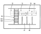
図3は、ある時刻Tにおいて画像取得部110が取得した画像である。
走路70は、時刻T-1から時刻Tの間における、自車両1の走路を示している。そして、走路71は、時刻T-2から時刻T-1の間における、自車両1の走路を示している。走路72は、時刻T-3から時刻T-2の間における、自車両1の走路を示している。そして、走行経路701は、時刻T-1から時刻Tの間における、自車両1の進行方向及び移動量を示している。所定の幅702は、走行経路701と直交し、所定の幅を持つ。
また、走行経路711は、時刻T-2から時刻T-1の間における、自車両1の進行方向及び移動量を示している。所定の幅712は、走行経路711と直交し、所定の幅を持つ。
また、走行経路721は、時刻T-3から時刻T-2の間における、自車両1の進行方向及び移動量を示している。所定の幅722は、走行経路721と直交し、所定の幅を持つ。
次に、図4を用いて、ECU10が、駐車枠を検出する具体的な様子を説明する。
図4は、あるタイミングである時刻Tにおけるリアカメラ21が撮影した画像を用いて画像取得部110が生成した、鳥瞰画像を示している。まず、鳥瞰画像には矢印40が存在している。また、鳥瞰画像には、横断歩道50が存在している。また、鳥瞰画像には、駐車区間60及び駐車区間61が存在している。この中から、ECU10は、駐車区間60及び駐車区間61を構成する駐車枠を検出する。
また、この鳥瞰画像には、時刻T-1から時刻Tの間における、自車両1の走路70及び走行経路701の情報が含まれている。また、過去のタイミングである時刻T-2から時刻T-1の間における、自車両1の走路71及び走行経路711の情報が含まれている。また、過去のタイミングである時刻T-3から時刻T-2の間における自車両1の、走路72及び走行経路721の情報が含まれている。
まず、直線検出部111は、上記で説明した方法を用いて、生成された鳥瞰画像から直線を検出する。すると、直線検出部111は、矢印40を構成する直線である、直線40aと直線40bとを検出する。また、直線検出部111は、横断歩道50を構成する直線である直線50aと直線50bとを検出する。また、直線検出部111は、駐車区間60を構成する直線である、直線60aと直線60bとを検出する。また、直線検出部111は駐車区間61を構成する直線61aと61bとを検出する。直線検出部111は、画像から他の直線も検出するが、説明の簡略化のために省略する。そのため、直線検出部111は、画像から8本の直線を検出する。
なお、直線60aと60bとの間の幅は2.5mである。また、直線61aと61bとの間の幅は2.5mである。また、直線50aと50bとの間の幅は2.0mである。そして、直線40aと直線40bとの間の幅は2.0mである。
次に、駐車枠候補検出部112が、駐車枠候補を検出する様子を説明する。
まず、直線60aと直線60bとを直線の組とした場合の例に、駐車枠候補検出部112が駐車枠候補を検出する様子を説明する。この時、駐車枠候補検出部112は、直線60aと直線60bとの平行の程度を判定する。すると、駐車枠候補検出部112は、直線60aと直線60bとのなす角の平行の程度が所定の範囲内に属しているかどうかを判定する。すると、直線60aと直線60bとのなす角の平行の程度は所定の範囲内に属している。また、駐車枠候補検出部112は、直線60aと直線60bとの間の幅が所定の範囲内に属しているかどうかを判定する。すると、この幅は2.5mであるため、駐車枠候補検出部112は、直線60aと直線60bとの直線間の幅が、所定の範囲を満たしていると判定する。このように、所定の条件を満たしているため、駐車枠候補検出部112は、直線60aと直線60bとの直線の組を、駐車枠候補として検出する。
次に、駐車枠候補検出部112が、直線40aと直線60aとを直線の組とした場合の例に、駐車枠候補として検出されない様子を説明する。この時、駐車枠候補検出部112は、直線40aと直線60aとの平行の程度を判定する。すると、直線40aと直線60aとのなす角はほぼ直交であり、平行の程度は所定の範囲内に属していない。そのため、直線40aと直線60aとの組は、駐車枠候補として検出されない。
同様にその他の直線の組み合わせに、上記処理を行った結果、今回、駐車枠候補として検出される直線の組は4組である。1つ目は、直線40aと直線40bとの組である。2つ目は、直線60aと直線60bとの組である。3つ目は直線61aと直線61bとの組である。4つ目は、直線50aと直線50bとの組である。
次に、いくつかの例を説明することで、本実施形態におけるECU10が駐車区間を構成する駐車枠を検出する様子を説明する。
1つ目の例として、駐車枠検出部113が、直線60aと直線60bとによって構成される駐車枠候補が、駐車区間を構成する駐車枠かどうかを判定する様子を示す。駐車枠検出部113は、自車両1の走行経路701と直線60aとのなす角を検出する。この時、なす角はほぼ90°であり、なす角の直交度は所定の範囲である45°~135°に属している。そのため、駐車枠検出部113は、直線60aと直線60bとによって構成される駐車枠候補を、駐車枠として検出する。
また、駐車枠検出部113が、直線40aと直線40bとによって構成される駐車枠候補が駐車枠かどうかを検出する様子を示す。駐車枠検出部113は、走行経路701と直線40aとのなす角を検出する。すると、そのなす角は、ほぼ0°となり、所定の範囲である45°~135°を満たさない。従って、駐車枠検出部113は、直線40aと直線40bとによって構成される駐車枠候補を駐車枠として検出しない。
また、駐車枠検出部113が、直線50aと直線50bとによって構成される駐車枠候補が駐車枠かどうかを検出する様子を示す。駐車枠検出部113は、走行経路701と直線50aとのなす角を検出する。すると、そのなす角は、ほぼ0°となり、所定の範囲である45°~135°を満たさない。従って、駐車枠検出部113は、直線50aと直線50bとによって構成される駐車枠候補を駐車枠として検出しない。
以上のように、本実施形態におけるECU10は、検出された駐車枠候補を構成する直線と自車両1の走行経路701とのなす角の直交度が、所定の範囲内に属するかどうかを判定する。そのため、矢印40や横断歩道50を駐車枠として誤検出してしまうことを防ぐことが出来る。
なお、走行経路711や走行経路721に基づいた駐車枠の検出は、過去のタイミングにてすでに行われている。すなわち、時刻T-1に画像取得部110が生成した鳥瞰画像上における駐車枠は、走行経路711と駐車枠候補とのなす角の直交度が所定の範囲内に属するかどうかに基づいて検出される。また、時刻T-2に画像取得部110が生成した鳥瞰画像上における駐車枠は、走行経路721と駐車枠候補とのなす角の直交度が所定の範囲内に属するかどうかに基づいて検出される。
次に、図5~図7を用いて、本実施形態におけるECU10が行う処理の流れを説明する。
図5に示すように、ステップS10において、ECU10は駐車枠候補を検出する。そして、ステップS11において、ECU10は、検出した駐車枠候補の中から、駐車枠を検出する。ステップS12において、ECU10は、検出した駐車枠をユーザに通知する。
図6は、ECU10が駐車枠候補を検出する具体的な処理の流れを示している。まず、ステップS101において、画像取得部110は、リアカメラ21から画像を取得する。また、画像取得部110は、取得した画像を鳥の視点から見た画像である鳥瞰画像を生成する。その後、ステップS102に進む。
ステップS102において、直線検出部111は、上記にて説明した方法で、生成された鳥瞰画像から直線を検出する。検出された直線は、メモリ12に記憶される。このステップは鳥瞰画像上における、全ての直線が検出されるまで、行われる。その後、ステップS103に進む。
ステップS103において、駐車枠候補検出部112は、直線検出部111が検出した直線から、任意の2本の直線を選択し直線の組とする。その後、ステップS104に進む。
ステップS104において、駐車枠候補検出部112は、直線の組が所定の条件を満たすかどうかを検出する。具体的に駐車枠候補検出部112は、直線の組の直線の間が1.8m~3.0mの範囲内に属しているかを判定する。また、駐車枠候補検出部112は、直線の組の直線同士の平行の程度が所定の範囲である、0°~45°または135°~180°に属しているかどうかを判定する。直線の組が所定の条件を満たしている場合ステップS105に進み、そうでなければステップS106に進む。
ステップS105において、駐車枠候補検出部112は、選択した直線の組を駐車枠候補としてメモリ12に書き込む。その後、ステップS106に進む
ステップS106において、駐車枠候補検出部112は、メモリ12に記憶された直線の、全ての組み合わせについて駐車枠候補かどうかを調べたかどうかを検出する。すべての組み合わせについて判定した場合、この処理を終了し、そうでなければステップS103に戻る。
ステップS106において、駐車枠候補検出部112は、メモリ12に記憶された直線の、全ての組み合わせについて駐車枠候補かどうかを調べたかどうかを検出する。すべての組み合わせについて判定した場合、この処理を終了し、そうでなければステップS103に戻る。
図7は、ECU10が、検出した駐車枠候補の中から、駐車枠を検出する具体的な処理の流れを示している。ステップS111において、駐車枠検出部113は、上記で説明した方法にて自車両1の走行経路701を検出する。その後、ステップS112に進む。
ステップS112において、駐車枠検出部113は、メモリ12に記憶されている任意の駐車枠候補を選択する。その後、ステップS113に進む
ステップS113において、駐車枠検出部113は、駐車枠候補を構成する直線の内少なくとも一方の直線と自車両1の走行経路701とのなす角の直交度が所定の範囲に属しているかどうかを判定する。所定の範囲内に属している場合ステップS114に進み、そうでなければステップS115に進む。
ステップS113において、駐車枠検出部113は、駐車枠候補を構成する直線の内少なくとも一方の直線と自車両1の走行経路701とのなす角の直交度が所定の範囲に属しているかどうかを判定する。所定の範囲内に属している場合ステップS114に進み、そうでなければステップS115に進む。
ステップS114において、駐車枠検出部113は、選択している駐車枠候補を駐車枠としてメモリ12に書き込む。また、駐車枠検出部113は、この駐車枠を検出した際の時刻をメモリ12に書き込む。その後、ステップS115に進む。
ステップS115において、駐車枠検出部113は、メモリ12に記憶されている全ての駐車枠候補に対して、駐車枠検出処理を行ったかどうかを判定する。全ての駐車枠候補に対して処理を行った場合処理を終了し、そうでなければ、ステップS112に戻る。
図8は、駐車枠検出部113が検出した駐車枠をユーザに通知する様子を示すフローチャートである。
ステップS121において、ECU10は、メモリ12から駐車枠を取得する。そして、取得した駐車枠を強調表示した状態で、自車両1の周辺画像を示す画像を生成する。具体的には、駐車枠を色つきマーカで囲う。そして、ECU10は、その画像を表示装置30に送信する。そして、表示装置30は、その画像を表示する。その後、ステップS122に進む。
ステップS122において、ユーザはその画像において強調表示された駐車枠のうち、1つの駐車枠を選択する。その時に、ECU10は、ユーザが選択した駐車枠の情報を表示装置30から受信する。その後、ステップS123に進む。
ステップS123において、ECU10は、ユーザが選択した駐車枠のみを強調表示した画像を生成し、表示装置30に送信する。そして、表示装置30は、ユーザが選択した駐車枠のみを強調表示した画像を表示する。その後、処理を終了する。
以下、第1実施形態におけるECU10の効果について説明する。
本実施形態におけるECU10は、自車両1の周辺を撮影するリアカメラ21から取得した画像を用いて、駐車区間を構成する駐車枠を検出するECU10である。そして、ECU10は、リアカメラ21から画像を取得する画像取得部110を備えている。また、ECU10は、画像取得部110が取得した画像から直線を検出する直線検出部111を備えている。また、ECU10は、直線検出部111が検出した複数の直線から選択された2つの直線によって構成される直線の組が所定の条件を満たす場合、当該直線の組を駐車枠候補として検出する駐車枠候補検出部112を備えている。また、ECU10は、駐車枠候補を構成する直線と自車両1の走行経路701とのなす角の直交度が所定の範囲内となる駐車枠候補を、駐車枠として検出する駐車枠検出部113を備えている。
このため、自車両1の走行経路701に対して直交する可能性が低い、道路の矢印40や横断歩道50などを駐車枠として誤検出してしまうことが低減される。一方、自車両1の走行経路701に対して直交する可能性が高い駐車区間を構成する駐車枠をより正確に検出することが出来る。
(第2実施形態)
第1実施形態において、駐車枠検出部113は、自車両1の走行経路と駐車枠候補とのなす角の直交度が所定の範囲内に属しているかどうかに基づいて、駐車枠を検出していた。
第1実施形態において、駐車枠検出部113は、自車両1の走行経路と駐車枠候補とのなす角の直交度が所定の範囲内に属しているかどうかに基づいて、駐車枠を検出していた。
第2実施形態における駐車枠検出部113は、自車両1の走行経路に対しての直交度が所定の範囲内に属する駐車枠候補でも、自車両1の過去または現在の走路上に位置している駐車枠候補は、駐車枠として検出することを禁止する。
なお、本実施形態におけるECU10の構成は、第1実施形態と同様であるので説明を省略する。
図9は、あるタイミング時刻Tにおいて、本実施形態における画像取得部110が生成した鳥瞰画像を示している。
第1実施形態と異なる点は、横断歩道50の長手方向に直線501と直線502とが存在している所である。そして、直線501と502との幅は、2.5mである。
この状況において、本実施形態におけるECU10は、以下の処理を行う。
まず、直線検出部111は、直線501と直線502とを検出する。そして、駐車枠候補検出部112は、直線501と直線502とによって構成される直線の組を、駐車枠候補として検出する。
次に駐車枠検出部113は、直線501と直線502との直線の組により構成される駐車枠候補と自車両1の走行経路701とのなす角の直交度が、所定の範囲に属するかどうかを判定する。
具体的に、駐車枠検出部113は、直線501と自車両1の走行経路701とのなす角の直交度が45°~135°に属しているかどうかを判定する。すると、なす角は90°であるため、所定の範囲内に属している。そのため、この時点において駐車枠検出部113は、直線501と直線502とによって構成される駐車枠候補を駐車枠として検出してしまう可能性がある。
本実施形態の駐車枠検出部113は、更に直線501が自車両1の過去または現在の走路上に位置しているかどうかを検出する。すなわち、駐車枠検出部113は、直線501が走路70、走路71または走路72に位置しているかどうかを判定する。そして、直線501がいずれかの走路に位置している場合、駐車枠検出部113は、直線501と直線502とによって構成される駐車枠候補を、駐車枠として検出することを禁止する。今回の場合、直線501は、走路72上に位置している。そのため、駐車枠検出部113は、直線501と直線502とによって構成される駐車枠候補を駐車枠として検出することを禁止する。
このように、本実施形態における駐車枠検出部113は、自車両1の走路上に位置している駐車枠候補を駐車枠として検出することを禁止する。
横断歩道50のように、自車両1の走路上には、自車両1の走行経路と略直交する駐車枠候補が出現することがある。しかし、駐車区間を構成する駐車枠が、自車両1の走路上に出現することは、実際にはほとんどありえない。
本実施形態のECU10は、仮に自車両1の走路上に、自車両1の走行経路と直交する駐車枠候補が検出されたとしても、そのような駐車枠候補を駐車枠として誤検出してしまうことを防ぐことが出来る。
以下、第2実施形態におけるECU10の効果について説明する。
駐車枠検出部113は、駐車枠候補のうち、走行経路に対して所定の幅を持つ走路上に位置する駐車枠候補を駐車枠として検出することを禁止すること。
駐車区間が自車両1の走路上に出現することはほとんどない。仮に自車両1の走行経路とのなす角がする駐車枠候補が自車両1の走路上に検出されても、本実施形態のECU10は上記特徴的な構成により、その駐車枠候補を駐車枠として誤検出してしまうことを防ぐことが出来る。
(第3実施形態)
第3実施形態におけるECU10は、あるタイミングにおいて駐車枠を検出する際に、あるタイミングより過去のタイミングに検出した駐車枠を参照する。そして、現在画像上に存在する駐車枠候補とメモリ12から取得した過去に検出された駐車枠とが対応している場合、その駐車枠候補を駐車枠として検出する。
第3実施形態におけるECU10は、あるタイミングにおいて駐車枠を検出する際に、あるタイミングより過去のタイミングに検出した駐車枠を参照する。そして、現在画像上に存在する駐車枠候補とメモリ12から取得した過去に検出された駐車枠とが対応している場合、その駐車枠候補を駐車枠として検出する。
現在の駐車枠候補とメモリ12から取得した駐車枠とが対応しているかどうかは、以下のような処理を行うことで検出される。
まず、駐車枠検出部113は、メモリ12から駐車枠と、過去に検出された際の画像上の位置座標を取得する。そして、現在のタイミングと駐車枠が検出された過去のタイミングと間に、自車両1が走行した走行経路を検出する。そして、駐車枠検出部113は、メモリ12から取得した駐車枠の過去の位置座標と上記走行経路とに基づいて、現在の画像上において駐車枠が存在するはずの位置座標を特定することが出来る。
そして、特定された位置座標に駐車枠候補が存在する場合、駐車枠検出部113は、その駐車枠候補を駐車枠として検出する。
具体的な例を、図10、図11、図12を用いて説明を行う。
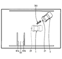
図10の破線が示す自車両1は、時刻T-1における自車両1を示している。そして、実線の自車両1は、時刻Tにおける自車両1を示している。自車両1は、時刻T-1から時刻Tの間に、走行経路701のように進行する。
図11は、時刻T-1における画像取得部110が生成する鳥瞰画像を示している。そして、図12は、時刻Tにおける画像取得部110が生成する鳥瞰画像を示している。
まず、図11に示すように時刻T-1において、駐車枠検出部113は、直線61aと直線61bとの組を駐車枠として検出する。そして、その駐車枠はメモリ12に記憶される。
次に、図12に示すように時刻Tにおいて、駐車枠候補検出部112は、直線61aと直線61bとの組を駐車枠候補として検出する。そして、駐車枠検出部113は、その駐車枠候補が駐車枠かどうかを判定する。すると、その駐車枠候補と自車両1の現在の走行経路701との直交度が所定の範囲に属していないので、駐車枠検出部113は、その駐車枠候補を駐車枠として検出しない。
本実施形態の駐車枠検出部113は、更に以下の処理を行う。まず、駐車枠検出部113は、メモリ12に記憶されている駐車枠を検出する。つまり、駐車枠検出部113は、直線61aと直線61bとの組を検出する。次に、駐車枠検出部113は、直線61aと直線61bとの組が駐車枠として検出された時刻T-1から、現在の時刻Tまでの走行経路を検出する。つまり、今回の場合、走行経路701である。そして、駐車枠検出部113は、過去の時刻T-1において、駐車枠が検出された位置座標と走行経路701とに基づいて、現在の駐車枠が存在するはずの位置座標を特定する。
そして、駐車枠検出部113は、現在の時刻Tにおいて検出された駐車枠候補のうち、上記の方法で特定した駐車枠が存在するはずの位置座標と一致する駐車枠候補を、駐車枠として検出する。すなわち、時刻T-1において、駐車枠として検出された直線61aと61bとの組は、時刻Tにおいても駐車枠として検出されることになる。
このように、本実施形態における駐車枠検出部113は、過去に一旦駐車枠として検出された駐車枠候補については、その駐車枠候補と現在の走行経路との直交度が所定の範囲を満たさなくても、駐車枠として検出することが出来る。
以下に第3実施形態におけるECU10の効果について説明する。
走行経路は、駐車枠検出部113が駐車枠の検知を前回行ったタイミングから現在迄に、自車両が進んだ走行経路であって、ECU10は駐車枠検出部113が過去に検出した駐車枠を記憶するメモリ12を備えている。駐車枠検出部113は、直交度が所定の範囲内となる駐車枠候補に加え、メモリ12が記憶している駐車枠と対応する駐車枠候補を駐車枠として検出する。
自車両1の進行方向が変化すると、自車両1の走行経路は変化する。そのため、あるタイミングにおいて、駐車枠として検出された駐車枠候補が、次のタイミングでは、自車両1の走行経路対するなす角の直交度が所定の範囲内に属さず、駐車枠として検出されない可能性がある。本実施形態におけるECU10は、一旦駐車枠として検出された駐車枠候補は、その後走行経路に対するなす角の直交度が所定の範囲内に属さなくなっても、駐車枠として検出することが出来る。
(第4実施形態)
上記実施形態においては、直線の組が所定の幅を満たし、かつ平行の程度が所定の範囲内に属する直線の組が、駐車枠候補として検出される。そして、駐車枠候補のうち、少なくとも一方の直線と走路との直交度が所定の範囲内に属しているものを全て同じ駐車枠として扱った。
上記実施形態においては、直線の組が所定の幅を満たし、かつ平行の程度が所定の範囲内に属する直線の組が、駐車枠候補として検出される。そして、駐車枠候補のうち、少なくとも一方の直線と走路との直交度が所定の範囲内に属しているものを全て同じ駐車枠として扱った。
本実施形態では、検出された駐車枠の内、より駐車枠の可能性が高いかどうかを判定するために、検出された駐車枠には駐車枠らしさの確率が設定される。
具体的には、図13~図15に示すように、各パラメータに対して確率が設定される。
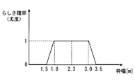
まず、図13は、上記直線の組の直線同士の幅と駐車枠らしさの確率との関係を示している。直線同士の幅が、1.8mから3.0mの範囲内の場合、駐車枠らしさの確率は1と設定される。そして、1.5m以下及び3.5m以上は、駐車枠らしさの確率が0と設定される。そして、枠幅をx1、駐車枠らしさの確率をAとした時、1.5m~1.8mの範囲内での確率Aは、所定の式、例えばA=(1/0.3)×(x1-1.5)により求められる。そして、3.0mから3.5mの範囲での確率Aは、所定の式、例えばA=2×(x1-3.0)により求められる。
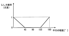
図14は、直線の組の直線同士の平行の程度と駐車枠らしさの確率との関係を示している。平行の程度をx2、駐車枠らしさの確率をBとした時、平行の程度0°から45°の範囲における確率Bは、所定の式、例えばB=(1/45)×(45-x2)により求められる。そして、平行の程度45°から135°の範囲においては、駐車枠らしさの確率Bは0となる。そして、平行の程度135°から180°の範囲における駐車枠らしさの確率Bは、所定の式、例えばB=(1/45)×(x2-135)により求められる。
図15は、直線の組の少なくとも一方の直線と自車両1の走行経路701との直交度と、駐車枠らしさの確率との関係を示している。直交度をx3とし、駐車枠らしさの確率をCとすると、直交度0°から45°の範囲内において、駐車枠らしさの確率C=0となる。そして、直交度45°から90°の範囲内において、駐車枠らしさの確率Cは、所定の式、例えばC=(1/45)×(x3―45)により求められる。直交度90°から135°の範囲内において、駐車枠らしさの確率Cは、所定の式、例えばC=(1/45)×(135-x3)により求められる。
そして、確率A、B及びCは、以下の計算式に基づいて統合され、最終的な駐車枠らしさの統合確率Eが検出される。
2つの確率を統合する、確率統合演算式を以下に示す。まず、上記確率AとBとの統合確率をDとした場合、統合確率をDは、所定の式、例えばD=(A×B)/(A×B+(1-A)×(1-B))により求められる。そして、上記確率統合演算式を、統合確率Dと直交度の確率Cとにも同様に適用し、DとCとの統合確率をEとすると、総合確率Eは、所定の式、例えばE=(D×C)/(D×C+(1-D)×(1-C))により求められる。この統合確率Eが、AとBとCとの統合確率である。
上記確率統合演算式を用いることで、駐車枠検出部113は、駐車枠候補同士のうち、どちらがより駐車枠らしいかどうかを判断できると共に、計算された駐車枠らしさの確率を用いて、駐車枠らしさの確率が閾値を超えたかどうかを判定することが出来る。例えば、駐車枠検出部113は、駐車枠らしさが50%以上であるもののうち、より駐車枠らしい駐車枠候補を検出することが出来る。
仮に、単純な確率の掛け合わせにした場合は、駐車枠検出部113は、駐車枠らしさの確率を掛け合わせるほど、最終的な駐車枠らしさの確率は減少してしまう。すなわち、駐車枠候補同士のうち、どちらがより駐車枠らしいかどうかのみしか判断できない。
具体的な例を示す。直線同士の枠幅が2.3m、平行の程度0°であり、直線の組の直線と走路との直交度が90°となる直線の組のそれぞれの確率は、A=1、B=1、C=1となる。そのため、統合確率E=1となる。
そして、直線同士の枠幅が1.6m、平行の程度30°であり、直線の組の直線と走路との直交度が70°の場合、直線の組のそれぞれの確率は、A=1/3、B=3/7、C=5/9となり、統合確率E=15/47となる。そして、検出された駐車枠の中でも、統合確率Eが高い方がより、駐車枠の可能性がある。
以下に第4実施形態におけるECU10の効果について説明する。
所定の条件は、直線同士の幅の長さが所定の範囲内に属することと、直線同士のなす角の平行の程度が所定の範囲内に属することである。そして、駐車枠検出部113は、幅の長さに基づいて設定される駐車枠らしさの確率と、平行の程度に基づいて設定される駐車枠らしさの確率と、直交度に基づいて設定される駐車枠らしさの確率とを統合した確率に基づき、駐車枠を検出する。
このように、本実施形態のECU10は、検出する駐車枠に対して、駐車枠の可能性を示す確率を設定する。このため、本実施形態におけるECU10は、駐車区間を構成する駐車枠である可能性がより高い駐車枠を検出することが出来る。
(他の実施形態)
以上、開示の好ましい実施形態について説明したが、開示は上述した実施形態に何ら制限されることなく、以下に例示するように種々変形して実施することが可能である。各実施形態で具体的に組合せが可能であることを明示している部分同士の組合せばかりではなく、特に組合せに支障が生じなければ、明示してなくとも実施形態同士を部分的に組み合せることも可能である。
以上、開示の好ましい実施形態について説明したが、開示は上述した実施形態に何ら制限されることなく、以下に例示するように種々変形して実施することが可能である。各実施形態で具体的に組合せが可能であることを明示している部分同士の組合せばかりではなく、特に組合せに支障が生じなければ、明示してなくとも実施形態同士を部分的に組み合せることも可能である。
上記第1実施形態において、駐車枠候補との直交度の判定が行われるのは、現在の走行経路だけであるが、過去の走行経路との比較も行うようにしてもよい。具体的には、第1実施形態において、時刻Tに画像取得部110が取得した画像における駐車枠候補と走行経路711とのなす角の直交度が所定の範囲に属しているかどうかを判定するようにしてもよい。更に、時刻Tに画像取得部110が取得した画像における駐車枠候補と走行経路721とのなす角の直交度が所定の範囲に属しているかどうかを判定するようにしてもよい。
また、上記第3実施形態において、直進する走行経路、および舵角を変化させる走行経路の両経路において、ECU10は、走行経路と駐車枠候補との直交度に基づいて駐車枠の検知を行っていた。本開示はこれに限るものではなく、自車両1が直進している際の走行経路と駐車枠候補との直交度に基づいて駐車枠を検知されるようにし、自車両1が直進していない場合の走行経路に基づいて駐車枠の検知を行なわれないようにしてもよい。駐車枠を探す必要がある状況は、自車両1が直進している場合がほとんどである。一方、自車両1のステアリングの舵角が切られている状態で、駐車枠を探す必要がある状況はほとんどない。そのため、自車両1のステアリングの舵角が切られた状態における走行経路に対して、直交度が所定の範囲を満たす駐車枠候補の直線は、駐車区間を形成する駐車枠ではない可能性が高い。そのため、上記の構成にすると、自車両1のステアリング舵角が切られている際に、ECU10が駐車枠を誤検出してしまうことを防ぐことが出来る。
上記実施形態において、駐車枠候補が検出される際の所定の条件として、直線同士の平行の程度及び直線同士の幅を用いたが、これに限るものではない。
例えば、直線同士の平行の程度または直線同士の幅のうち、どちらか一方のみを採用して、駐車枠候補が検出されるようにしてもよい。
例えば、2本の直線の内、片方の直線の付近に、別の直線が存在しているかどうかを検出するようにしてもよい。
また、2本の直線同士の線の一致度を比較するようにしてもよい。具体的に直線同士の一致度に関するパラメータとして、色、輝度、長さ、太さ、形状、コントラストなどである。上記パラメータを少なくとも1つ採用するようにしてもよい。更に言うと、各パラメータに対しても、上記第4実施形態で示したような駐車枠らしさを設定し、直線同士の幅、平行度及び直交度の駐車枠らしさに加えて、各パラメータの駐車枠らしさに基づいて、最終的な駐車枠らしさを計算するようにしてもよい。
つまり、上記所定の条件は、直線同士の輝度が一致する、コントラストが一致する、長さが一致する、太さが一致する、色が一致する、及び直線同士の幅の長さが所定の範囲内に属する直線の組が連続して出現することを、少なくとも1つ満たすことである。
駐車枠検出部は、輝度の一致度に基づいて設定される駐車枠らしさの確率、コントラストの一致度に基づいて設定される駐車枠らしさの確率、長さの一致度に基づいて設定される駐車枠らしさの確率、太さの一致度に基づいて設定される駐車枠らしさの確率、色の一致度に基づいて設定される駐車枠らしさの確率、及び直線同士の幅の長さが所定の範囲内に属する直線の組が連続している度合に基づいて設定される駐車枠らしさの確率のうち、少なくとも1つの駐車枠らしさの確率を統合した確率に基づき、駐車枠を検出してもよい。
また、直線同士の幅や色が同じような、直線の組が複数個、所定方向に連続して出現しているかどうかを考慮して、駐車枠を検出するようにしてもよい。更に言うと、直線同士の幅や色が同じものが連続しているかどうかについて、駐車枠らしさを設定し、最終的な駐車枠らしさの計算に用いるようにしてもよい。
また、駐車枠検出部113は、上記直線同士の幅や平行度などに基づき、駐車枠候補が横断歩道かどうかを判定する処理を行い、横断歩道と判定された駐車枠候補は、駐車枠として検出しないようにしてもよい。
あるいは、駐車枠検出部113は、上記直線同士の幅や平行度などに基づき、駐車枠候補が文字かどうかを判定する処理を行い、文字と判定された駐車枠候補は、駐車枠として検出しないようにしてもよい。
また、自車両1の走行経路の検出方法は上記実施形態に限るものではない。例えば、GPSに基づいて、各タイミングにおける自車両1の位置を特定し、その差分を利用して走行経路を求めるようにしてもよい。また、各タイミング間における任意のエッジ点の座標変化量に基づいて、自車両1の走行経路を計算するようにしてもよい。
また、上記実施形態において、直交度の所定の範囲として45°~135°としたが、当然これに限るものではなく、適宜設定することが出来る。例えば、80°~120°としてもよい。同様に平行の程度や幅の長さの所定の範囲についても、適宜設定することが出来る。
なお、上記実施形態において、走行経路は移動方向とその移動量との両方を含んでいたが、移動方向だけの情報を含むようにしてもよい。
なお、上記実施形態における駐車枠検出部113は、画像取得部110が鳥瞰画像を生成する毎に駐車枠の検出を行っていたが、画像取得部110が所定回数鳥瞰画像を生成した後に、駐車枠の検出を行うようにしてもよい。
なお、上記実施形態において、駐車枠記憶部はECU10内に設けられるメモリ12としたが、ECU10とは別の装置の記憶媒体としてもよい。
また、上記実施形態において、撮像装置はリアカメラ21としたが、複数のカメラを自車両1に取り付けて、画像取得部110は複数のカメラから鳥瞰画像を生成するようにしてもよい。
また、上記実施形態において、直線検出部111は画像取得部110が生成した鳥瞰画像に対して直線の検出を行った。これに限るものではなく、直線検出部111は、画像取得部110がリアカメラ21から取得した画像に対して、歪処理を行った後の画像に対して直線検出を行うようにしてもよい。
本開示に記載されるフローチャート、あるいは、フローチャートの処理は、複数の部(あるいはステップと言及される)から構成され、各部は、たとえば、S10と表現される。さらに、各部は、複数のサブ部に分割されることができる、一方、複数の部が合わさって一つの部にすることも可能である。さらに、このように構成される各部は、サーキット、デバイス、モジュール、ミーンズとして言及されることができる。
また、上記の複数の部の各々あるいは組合わさったものは、(i) ハードウエアユニット(例えば、コンピュータ)と組み合わさったソフトウエアの部のみならず、(ii) ハードウエア(例えば、集積回路、配線論理回路)の部として、関連する装置の機能を含みあるいは含まずに実現できる。さらに、ハードウエアの部は、マイクロコンピュータの内部に構成されることもできる。
本開示は、実施例に準拠して記述されたが、本開示は当該実施例や構造に限定されるものではないと理解される。本開示は、様々な変形例や均等範囲内の変形をも包含する。加えて、様々な組み合わせや形態、さらには、それらに一要素のみ、それ以上、あるいはそれ以下、を含む他の組み合わせや形態をも、本開示の範畴や思想範囲に入るものである。
Claims (5)
- 自車両の周辺を撮影する撮像装置から取得した画像を用いて、駐車区間を構成する駐車枠を検出する車載画像処理装置であって、
前記撮像装置から画像を取得する画像取得部(110)と、
前記画像取得部が取得した前記画像から複数の直線を検出する直線検出部(111)と、
前記直線検出部が検出した複数の前記直線から選択された2つの直線によって構成される前記直線の組が所定の条件を満たす場合、当該直線の組を駐車枠候補として検出する駐車枠候補検出部(112)と、
前記駐車枠候補を構成する前記直線と前記自車両の走行経路とのなす角の直交度が所定の範囲内となる前記駐車枠候補を、前記駐車枠として検出する駐車枠検出部(113)とを備えた車載画像処理装置。 - 前記駐車枠検出部は、前記駐車枠候補のうち、前記走行経路に対して所定の幅を持つ走路上に位置する前記駐車枠候補を前記駐車枠として検出することを禁止する、請求項1に記載の車載画像処理装置。
- 前記走行経路は、前記駐車枠検出部が前記駐車枠の検出を前回行ったタイミングから現在迄に、前記自車両が進んだ走行経路であって、
前記駐車枠検出部が過去に検出した前記駐車枠を記憶する駐車枠記憶部(12)をさらに備え、
前記駐車枠検出部は、前記直交度が所定の範囲内となる前記駐車枠候補に加え、前記駐車枠記憶部が記憶している前記駐車枠と対応する前記駐車枠候補を、前記駐車枠として検出する、請求項1または2に記載の車載画像処理装置。 - 前記所定の条件は、前記直線同士の幅の長さが所定の範囲内に属することと、前記直線同士のなす角の平行の程度が所定の範囲内に属することを満たすことであって、
前記駐車枠検出部は、前記幅の長さに基づいて設定される駐車枠らしさの確率と、前記平行の程度に基づいて設定される駐車枠らしさの確率と、前記直交度に基づいて設定される駐車枠らしさの確率とを統合した確率に基づき、前記駐車枠を検出する、請求項1ないし3のいずれか1項に記載の車載画像処理装置。 - 前記所定の条件は、更に、前記直線同士の輝度が一致する、コントラストが一致する、長さが一致する、太さが一致する、色が一致する、及び前記直線同士の幅の長さが所定の範囲内に属する直線の組が連続して出現することを、少なくとも1つ満たすことであって、
前記駐車枠検出部は、更に、前記輝度の一致度に基づいて設定される駐車枠らしさの確率、前記コントラストの一致度に基づいて設定される駐車枠らしさの確率、前記長さの一致度に基づいて設定される駐車枠らしさの確率、前記太さの一致度に基づいて設定される駐車枠らしさの確率、前記色の一致度に基づいて設定される駐車枠らしさの確率、及び前記直線同士の幅の長さが所定の範囲内に属する直線の組が連続している度合に基づいて設定される駐車枠らしさの確率のうち、少なくとも1つの駐車枠らしさの確率を統合した確率に基づき、前記駐車枠を検出する請求項4に記載の車載画像処理装置。
Priority Applications (1)
| Application Number | Priority Date | Filing Date | Title |
|---|---|---|---|
| DE112015002593.6T DE112015002593T5 (de) | 2014-06-02 | 2015-05-08 | Fahrzeugmontierte bildverarbeitungsvorrichtung |
Applications Claiming Priority (2)
| Application Number | Priority Date | Filing Date | Title |
|---|---|---|---|
| JP2014-114205 | 2014-06-02 | ||
| JP2014114205A JP6459226B2 (ja) | 2014-06-02 | 2014-06-02 | 車載画像処理装置 |
Publications (1)
| Publication Number | Publication Date |
|---|---|
| WO2015186294A1 true WO2015186294A1 (ja) | 2015-12-10 |
Family
ID=54766381
Family Applications (1)
| Application Number | Title | Priority Date | Filing Date |
|---|---|---|---|
| PCT/JP2015/002349 Ceased WO2015186294A1 (ja) | 2014-06-02 | 2015-05-08 | 車載画像処理装置 |
Country Status (3)
| Country | Link |
|---|---|
| JP (1) | JP6459226B2 (ja) |
| DE (1) | DE112015002593T5 (ja) |
| WO (1) | WO2015186294A1 (ja) |
Cited By (4)
| Publication number | Priority date | Publication date | Assignee | Title |
|---|---|---|---|---|
| US20140249752A1 (en) * | 2011-09-30 | 2014-09-04 | The Chancellor Masters And Scholars Of The University Of Oxford | Localising a vehicle along a route |
| GB2559250A (en) * | 2016-12-09 | 2018-08-01 | Ford Global Tech Llc | Parking-lot-navigation system and method |
| CN109299686A (zh) * | 2018-09-14 | 2019-02-01 | 深圳市灵动飞扬科技有限公司 | 一种车位识别方法、装置、设备及介质 |
| CN113792601A (zh) * | 2021-08-10 | 2021-12-14 | 武汉光庭信息技术股份有限公司 | 基于霍夫直线检测结果的车位线拟合方法及系统 |
Families Citing this family (7)
| Publication number | Priority date | Publication date | Assignee | Title |
|---|---|---|---|---|
| JP6642906B2 (ja) * | 2016-02-18 | 2020-02-12 | 三菱重工業株式会社 | 駐車位置検出システム及びそれを用いた自動駐車システム |
| JP6958117B2 (ja) | 2017-08-29 | 2021-11-02 | 株式会社アイシン | 駐車支援装置 |
| KR102429494B1 (ko) | 2017-10-13 | 2022-08-05 | 현대자동차주식회사 | 차량의 목표주차공간 표시 장치 및 그 방법 |
| JP2019196075A (ja) * | 2018-05-09 | 2019-11-14 | 株式会社デンソーテン | 駐車枠検出装置および駐車枠検出方法 |
| JP7188916B2 (ja) | 2018-06-26 | 2022-12-13 | フォルシアクラリオン・エレクトロニクス株式会社 | 駐車支援装置 |
| DE102018123393A1 (de) * | 2018-09-24 | 2020-03-26 | Denso Corporation | Erkennung von Parkflächen |
| JP2020095631A (ja) * | 2018-12-14 | 2020-06-18 | 株式会社デンソーテン | 画像処理装置および画像処理方法 |
Citations (10)
| Publication number | Priority date | Publication date | Assignee | Title |
|---|---|---|---|---|
| JP2003270344A (ja) * | 2002-03-14 | 2003-09-25 | Nissan Motor Co Ltd | 車両用駐車方向設定装置 |
| JP2006129021A (ja) * | 2004-10-28 | 2006-05-18 | Denso Corp | 駐車支援システム |
| JP2007052730A (ja) * | 2005-08-19 | 2007-03-01 | Toyota Motor Corp | 走行路認識装置 |
| JP2008083990A (ja) * | 2006-09-27 | 2008-04-10 | Aisin Aw Co Ltd | 駐車支援装置および駐車支援方法 |
| JP2009202610A (ja) * | 2008-02-26 | 2009-09-10 | Hitachi Ltd | 駐車支援装置 |
| JP2009251860A (ja) * | 2008-04-04 | 2009-10-29 | Toyota Motor Corp | 駐車支援装置 |
| WO2011039822A1 (ja) * | 2009-10-02 | 2011-04-07 | 三菱電機株式会社 | 駐車支援装置 |
| JP2011207383A (ja) * | 2010-03-30 | 2011-10-20 | Denso Corp | 後退駐車支援制御装置および後退駐車支援制御装置用のプログラム |
| JP2012080497A (ja) * | 2010-10-06 | 2012-04-19 | Suzuki Motor Corp | 駐車枠検出装置及び駐車枠検出方法 |
| JP2014058309A (ja) * | 2009-06-09 | 2014-04-03 | Denso Corp | 駐車支援システム |
Family Cites Families (6)
| Publication number | Priority date | Publication date | Assignee | Title |
|---|---|---|---|---|
| JP2010183234A (ja) * | 2009-02-04 | 2010-08-19 | Panasonic Corp | 描画装置 |
| JP5035284B2 (ja) * | 2009-03-25 | 2012-09-26 | 株式会社日本自動車部品総合研究所 | 車両周辺表示装置 |
| JP2012136206A (ja) * | 2010-12-28 | 2012-07-19 | Fujitsu Ten Ltd | 駐車制御システム、及び、駐車制御方法 |
| JP2013018406A (ja) * | 2011-07-12 | 2013-01-31 | Fujitsu Ten Ltd | 駐車枠の認識装置、駐車枠の認識方法、及び、プログラム |
| JP2013186663A (ja) * | 2012-03-07 | 2013-09-19 | Toyota Motor Corp | 横断歩道認識装置および横断歩道認識方法 |
| JP2014106739A (ja) * | 2012-11-27 | 2014-06-09 | Clarion Co Ltd | 車載画像処理装置 |
-
2014
- 2014-06-02 JP JP2014114205A patent/JP6459226B2/ja active Active
-
2015
- 2015-05-08 WO PCT/JP2015/002349 patent/WO2015186294A1/ja not_active Ceased
- 2015-05-08 DE DE112015002593.6T patent/DE112015002593T5/de not_active Ceased
Patent Citations (10)
| Publication number | Priority date | Publication date | Assignee | Title |
|---|---|---|---|---|
| JP2003270344A (ja) * | 2002-03-14 | 2003-09-25 | Nissan Motor Co Ltd | 車両用駐車方向設定装置 |
| JP2006129021A (ja) * | 2004-10-28 | 2006-05-18 | Denso Corp | 駐車支援システム |
| JP2007052730A (ja) * | 2005-08-19 | 2007-03-01 | Toyota Motor Corp | 走行路認識装置 |
| JP2008083990A (ja) * | 2006-09-27 | 2008-04-10 | Aisin Aw Co Ltd | 駐車支援装置および駐車支援方法 |
| JP2009202610A (ja) * | 2008-02-26 | 2009-09-10 | Hitachi Ltd | 駐車支援装置 |
| JP2009251860A (ja) * | 2008-04-04 | 2009-10-29 | Toyota Motor Corp | 駐車支援装置 |
| JP2014058309A (ja) * | 2009-06-09 | 2014-04-03 | Denso Corp | 駐車支援システム |
| WO2011039822A1 (ja) * | 2009-10-02 | 2011-04-07 | 三菱電機株式会社 | 駐車支援装置 |
| JP2011207383A (ja) * | 2010-03-30 | 2011-10-20 | Denso Corp | 後退駐車支援制御装置および後退駐車支援制御装置用のプログラム |
| JP2012080497A (ja) * | 2010-10-06 | 2012-04-19 | Suzuki Motor Corp | 駐車枠検出装置及び駐車枠検出方法 |
Cited By (7)
| Publication number | Priority date | Publication date | Assignee | Title |
|---|---|---|---|---|
| US20140249752A1 (en) * | 2011-09-30 | 2014-09-04 | The Chancellor Masters And Scholars Of The University Of Oxford | Localising a vehicle along a route |
| US9464894B2 (en) * | 2011-09-30 | 2016-10-11 | Bae Systems Plc | Localising a vehicle along a route |
| GB2559250A (en) * | 2016-12-09 | 2018-08-01 | Ford Global Tech Llc | Parking-lot-navigation system and method |
| US10481609B2 (en) | 2016-12-09 | 2019-11-19 | Ford Global Technologies, Llc | Parking-lot-navigation system and method |
| CN109299686A (zh) * | 2018-09-14 | 2019-02-01 | 深圳市灵动飞扬科技有限公司 | 一种车位识别方法、装置、设备及介质 |
| CN113792601A (zh) * | 2021-08-10 | 2021-12-14 | 武汉光庭信息技术股份有限公司 | 基于霍夫直线检测结果的车位线拟合方法及系统 |
| CN113792601B (zh) * | 2021-08-10 | 2024-01-12 | 武汉光庭信息技术股份有限公司 | 基于霍夫直线检测结果的车位线拟合方法及系统 |
Also Published As
| Publication number | Publication date |
|---|---|
| DE112015002593T5 (de) | 2017-04-06 |
| JP6459226B2 (ja) | 2019-01-30 |
| JP2015227139A (ja) | 2015-12-17 |
Similar Documents
| Publication | Publication Date | Title |
|---|---|---|
| JP6459226B2 (ja) | 車載画像処理装置 | |
| US10795370B2 (en) | Travel assist apparatus | |
| US9569673B2 (en) | Method and device for detecting a position of a vehicle on a lane | |
| US10169669B2 (en) | Driving assistance apparatus and driving assistance method | |
| US9619719B2 (en) | Systems and methods for detecting traffic signs | |
| CN102649408B (zh) | 车道偏离警报装置以及车道偏离警报系统 | |
| JP6628189B2 (ja) | 検出装置および検出方法 | |
| JP4973736B2 (ja) | 路面標示認識装置,路面標示認識方法及び路面標示認識プログラム | |
| JP6747269B2 (ja) | 物体認識装置 | |
| KR101500082B1 (ko) | 주행차로 인식 장치 및 방법 | |
| CN106463051B (zh) | 信号机识别装置以及信号机识别方法 | |
| JP6450294B2 (ja) | 物体検出装置、物体検出方法、及びプログラム | |
| KR20200042760A (ko) | 차량 위치 결정 방법 및 차량 위치 결정 장치 | |
| JP6140658B2 (ja) | 走行区画線認識装置、走行区画線認識プログラム | |
| JP6586849B2 (ja) | 情報表示装置及び情報表示方法 | |
| JP6649859B2 (ja) | 自車位置推定装置、自車位置推定方法 | |
| US11468691B2 (en) | Traveling lane recognition apparatus and traveling lane recognition method | |
| JP4948338B2 (ja) | 車間距離計測装置 | |
| US20170103271A1 (en) | Driving assistance system and driving assistance method for vehicle | |
| JP5974923B2 (ja) | 道路端検出システム、方法およびプログラム | |
| CN107886729B (zh) | 车辆识别方法、装置及车辆 | |
| CN113903103B (zh) | 局部图像生成装置、局部图像生成方法以及存储介质 | |
| US9824449B2 (en) | Object recognition and pedestrian alert apparatus for a vehicle | |
| KR102003387B1 (ko) | 조감도 이미지를 이용한 교통 장애물의 검출 및 거리 측정 방법, 교통 장애물을 검출하고 거리를 측정하는 프로그램을 저장한 컴퓨터 판독가능 기록매체 | |
| JP5097681B2 (ja) | 地物位置認識装置 |
Legal Events
| Date | Code | Title | Description |
|---|---|---|---|
| 121 | Ep: the epo has been informed by wipo that ep was designated in this application |
Ref document number: 15802418 Country of ref document: EP Kind code of ref document: A1 |
|
| WWE | Wipo information: entry into national phase |
Ref document number: 112015002593 Country of ref document: DE |
|
| 122 | Ep: pct application non-entry in european phase |
Ref document number: 15802418 Country of ref document: EP Kind code of ref document: A1 |