WO2015186232A1 - 回転電機システムまたは回転電機システムの制御方法 - Google Patents
回転電機システムまたは回転電機システムの制御方法 Download PDFInfo
- Publication number
- WO2015186232A1 WO2015186232A1 PCT/JP2014/065030 JP2014065030W WO2015186232A1 WO 2015186232 A1 WO2015186232 A1 WO 2015186232A1 JP 2014065030 W JP2014065030 W JP 2014065030W WO 2015186232 A1 WO2015186232 A1 WO 2015186232A1
- Authority
- WO
- WIPO (PCT)
- Prior art keywords
- voltage
- machine system
- power converter
- electrical machine
- rotating electrical
- Prior art date
- Legal status (The legal status is an assumption and is not a legal conclusion. Google has not performed a legal analysis and makes no representation as to the accuracy of the status listed.)
- Ceased
Links
Images





Classifications
-
- H—ELECTRICITY
- H02—GENERATION; CONVERSION OR DISTRIBUTION OF ELECTRIC POWER
- H02P—CONTROL OR REGULATION OF ELECTRIC MOTORS, ELECTRIC GENERATORS OR DYNAMO-ELECTRIC CONVERTERS; CONTROLLING TRANSFORMERS, REACTORS OR CHOKE COILS
- H02P9/00—Arrangements for controlling electric generators for the purpose of obtaining a desired output
Definitions
- the present invention relates to a rotating electrical machine system or a method for controlling a rotating electrical machine system, and is particularly suitable for use in wind power generation.
- the wound secondary excitation generator When a voltage drop occurs due to a ground fault in the power system, the wound secondary excitation generator operates to supply current to the point of failure. This induces an excessive current in the rotor winding. This excessive current is fixed so that the smoothing capacitor is charged with the spark pulse of the self-extinguishing semiconductor switching element such as IGBT of the power converter on the winding type secondary excitation generator side of the power converter.
- a method of suppressing power consumption by an energy consumer including a resistance chopper circuit provided in parallel with a capacitor is used.
- An object of the present invention is to provide a rotating electrical machine system or a control method for a rotating electrical machine system that can suppress energy flowing into a livestock generator of a power converter.
- a rotating electrical machine system includes a stator having stator windings for each phase, and a rotor winding for each phase that is installed with a gap between the stator and the stator.
- a rotating machine including a rotor having a power supply, a power converter connected to the rotor winding and switching between direct current and alternating current, a capacitor connected to a direct current side of the power converter, and at least the rotor winding
- a voltage detector that detects any one of an applied voltage, a voltage applied to the stator winding, or a voltage of a power system connected to the stator winding, or any of the voltages by calculation
- control method of the rotating electrical machine system includes a stator having a stator winding of each phase, and a rotor that is installed with a gap from the stator and has a rotor winding of each phase.
- a method of controlling a rotating electrical machine system comprising: a rotating machine including: a power converter connected to the rotor winding; and switching between direct current and alternating current; and a capacitor connected to a direct current side of the power converter, Detect or calculate at least one of a voltage applied to the rotor winding, a voltage applied to the stator winding, or a voltage of a power system connected to the stator winding, and at least one of them When the voltage drop is detected and a voltage drop is detected, the same voltage command for each phase is output to the power converter.
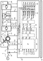
- Winding type secondary excitation power generation system Generated pulse according to the first embodiment Current path in state I Current path in state II Current path in state III Winding type secondary excitation power generation system according to the second embodiment Generated pulses according to the second embodiment Winding type secondary excitation power generation system according to the third embodiment Generated pulses according to the third embodiment Winding type secondary excitation power generation system according to the fourth embodiment
- stator winding (4) of the wound secondary excitation generator (2) is connected to the power system (1), and the rotor winding (3) is connected to a self-extinguishing semiconductor switching element such as an IGBT.
- the AC terminal side of the power converter (7) composed of a semiconductor switching module (28) composed of diodes connected in antiparallel is connected thereto.
- the smoothing capacitor (8) which is a kind of livestock machine, and the energy consumer (9) comprised, for example with a resistance chopper circuit etc. are connected to the direct current
- a voltage drop detector (24) that receives the voltage detection values (V, Vst) of the voltage detector (10, 12) for detecting the voltage of the stator winding (4) or the voltage of the power system (1).
- V, Vst voltage detection values
- the voltage command value selector (19) The output voltage command value is set to the same value, and the semiconductor switching module is driven according to the same output voltage command value.
- the voltage detector (10, 12) includes at least a voltage applied to the rotor winding (3), a voltage applied to the stator winding (4), or a power connected to the stator winding (4). It can be configured to detect any of the system voltages.
- a voltage drop detector (24) for detecting the detected voltage drop is provided. When the voltage drop detector (24) detects a voltage drop, the power converter (7, 7 ') The same voltage command is output. By doing so, the rotor winding (3) is short-circuited with the voltage difference between the phases being zero, and the energy of the overcurrent due to the accident in the power system (1) is the DC terminal of the power converter (7, 7 '). Inflow to the smoothing capacitor (8) on the side can be suppressed.
- FIG. 1 shows an example in which the secondary excitation variable speed power generation system according to this embodiment is applied to a wind power generation system.
- the stator winding (4) of the wound secondary excitation generator (2) is connected to the power system (1) through a device such as a breaker.
- a semiconductor switching module (28) composed of a self-extinguishing semiconductor switching element such as IGBT and a diode connected in reverse parallel thereto is connected in series or in parallel with a plurality of modules.
- An AC terminal side of a power converter (7) generally called a two-level converter or a three-level converter is connected, and a smoothing capacitor (8) and a resistance chopper are connected to the DC terminal side of the power converter (7).
- An energy consumer (9) composed of a circuit or the like is connected.
- the secondary excitation variable speed power generation system is a system that is operated by alternating current excitation of the wound secondary excitation generator (2) by the power converter (7).
- the wound secondary excitation generator (2) is connected to the blade (6) through a shaft (5) and a gear (not shown), and the blade and the blade rotate by receiving wind to rotate the shaft and gear.
- the rotor of the wound secondary excitation generator (2) also rotates.
- the control device (15) of the power converter (7) incorporated in the secondary excitation variable speed power generation system shown in FIG. 1 is an input from the detector group (10 to 14) and a host control device.
- the secondary excitation variable speed power generation system is controlled in accordance with an active power command (P * ) and a reactive power command (Q * ) given from the wind turbine controller (16).
- the detector group includes a rotor of the wound secondary excitation generator (2), a rotational speed detector for detecting the rotational speed (rot) of the shaft, gear, or blade, and the voltage of the power system (1) ( Voltage detector (10) for detecting V), current detector (11) for detecting current (I) of the power system (1), power system side (primary side) of the wound secondary excitation generator (2) ) Voltage detector (12) for detecting the voltage (Vst), and current detector (13) for detecting the current (Irt) on the power converter side (secondary side) of the wound secondary excitation generator (2). And a voltage detector (14) for detecting the voltage (Vdc) of the smoothing capacitor (8) in the DC section of the power converter (7).
- a rotating electrical machine system used as a secondary excitation variable speed power generation system is a wound secondary excitation generator (2) by a power converter (7).
- the rotor winding (3) is excited with a sliding frequency (difference between the frequency of the power system (1) and the rotation frequency of the rotor), so that the frequency of the power system (1) is applied to the stator winding (4). Can be generated.
- the variable speed of the secondary excitation variable speed power generation system (FIG. 1) is made variable by changing the slip frequency of the AC excitation voltage applied to the rotor following the fluctuation of the rotation speed of the rotor (the rotational speed of the shaft of the windmill). Driving is realized.
- variable speed operation only a part of the electric power generated by the wound secondary excitation generator (2) flows to the power system (1) via the power converter (7).
- the capacity of the power converter (7) can be made smaller than the capacity of the machine (2).
- the power converter (7) is reduced in size, and since the amount of power handled is small, there is an advantage that there is little loss caused by power conversion and high-efficiency power generation operation is possible.
- a current detector (29) for detecting the current on the AC side of the power converter (7 ′) is provided, and Kirchoff's current law and detection to be detected are provided. It is also possible to substitute the detection value by the current detector (11) or (13) by performing a correction calculation using the impedance information between the points.
- the voltage detectors (10) and (12) can also be used as substitutes for the detection values of the voltage detectors described above even when they are provided at equipment connection locations other than those shown in the figure by performing correction calculations according to Kirchoff's voltage rule. It is possible.
- detection values are all assumed to be detection values, and correction calculation processing in the case of using estimated values based on the above correction calculation will not be described in detail. However, it is possible to perform the same control using the estimated value.
- the control block diagram shown in FIG. 1 illustrates only the control block related to the present invention, and the normal power generation not related to the manifestation of the effect of the present invention for the secondary excitation variable speed power generation system and the wind power generation system to which the secondary excitation variable speed power generation system is applied.
- the control in operation only the outline will be described below, and the details will be omitted.
- the active power command (P * ) and the reactive power command (Q * ) given from the wind turbine controller (16) which is the host controller the detected values from the detector group (10 to 14) are used,
- the generation of the driving pulse of the switching module is not limited to the method described in the following outline.
- the DQ voltage command value calculator (17) of the control device (15) of the power converter (7) includes a rotation speed detection value (rot) of the rotation speed detector, a power system (1), or a wound secondary excitation generator.
- a rotation speed detection value (rot) of the rotation speed detector rot
- a power system (1) or a wound secondary excitation generator.
- V or Vst Voltage detection value on the power system side (primary side)
- current detection value (I) of the power system and active power command (16) provided from the wind turbine controller (16) which is the host controller.
- P * ) and reactive power command (Q * ) are input.
- the power system (1) has a system frequency of 50 Hz or 60 Hz, and the AC 3 phase (UVW) is 120 degrees behind the U phase and the W phase is the V phase.
- the positive phase voltage component and the positive phase current component in the order of 120 degrees phase lag are calculated, and the active power P and the reactive power Q are calculated from these positive phase components. Proportional so that the deviation between the calculated active power P and reactive power Q and the active power command (P * ) and reactive power command (Q * ) given from the wind turbine controller (16), which is the host controller, is minimized.
- a current command value (Irt * ) on the power converter side (secondary side) of the wound secondary excitation generator (2) is calculated using feedback control such as integral control. Proportional integral control or the like so that the deviation between the calculated current command value (Irt * ) and the detected current value (Irt) on the power converter side (secondary side) of the wound secondary excitation generator (2) is minimized.
- the voltage command value (Vd * , Vq * ) on the DQ axis to be output by the power converter (7) is calculated using the feedback control. Further, the phase information is extracted from the positive phase voltage component described above, and the electrical angle phase information of the rotor is calculated from the rotation speed detection value (rot). The slip phase angle information (slip) is calculated from the phase angle information.
- the voltage command values (Vd * , Vq * ) and slip phase angle information (slip) on the DQ axis are input to the DQ / 3-phase coordinate converter (18), and the three-phase voltage command values (Vu *). , Vv * , Vw * ).
- the calculated three-phase voltage command values (Vu * , Vv * , Vw * ) are input to the voltage command value selector (19), and input from the DQ / 3-phase coordinate converter (18) in normal power generation operation. Is output to the PWM pulse generator.
- the PWM pulse generator generates power based on the magnitude comparison between the input three-phase voltage command value (Vu * , Vv * , Vw * ) and the instantaneous value of the carrier wave such as a triangular sawtooth waveform generated internally.
- Drive pulses (Pu, Pv, Pw) for the semiconductor switching module of the converter (7) are generated.
- the PWM pulse generator and the number of drive pulses to be output depend on the main circuit configuration (2 levels, 3 levels, etc.) of the power converter (7), and FIG. 1 corresponds to the case of the 2-level power converter (7). .
- the generated drive pulse (Pu, Pv, Pw) becomes a drive pulse for the semiconductor switching module on the positive side of the power converter (7), and the negative pole of the power converter (7) by the NOT circuit.
- Drive pulses for the semiconductor switching module on the side are generated.
- a dead time circuit (21) that prevents the semiconductor switching module on the positive electrode side and the negative electrode side from being simultaneously turned ON and the DC smoothing capacitor (8) is short-circuited, and prevents the semiconductor switching module from switching operation with an excess current.
- Drive pulses (Pup, Pun, Pvp, Pvn, Pwp, Pwn) are transmitted to each semiconductor switching module via the gate block circuit.
- the on-delay time is t 0 and the time width is sufficient to prevent the smoothing capacitor (8) from being short-circuited.
- the overcurrent detector (23) receives the current detection value (Irt) of the current detector (13) for detecting the current flowing through the rotor winding (3) of the wound secondary excitation generator (2) as an input, With the determination condition that the absolute value of the detected current value of the three phases exceeds a predetermined value, it is determined whether or not an overcurrent has occurred, and an overcurrent determination signal (OC) (1 if no overcurrent is generated) Is set to 0).
- the gate block circuit (22) suppresses the operation of the semiconductor switching module when the above-described overcurrent determination signal (OC) is input as 0 (gate block operation). As a result, since the power converter (7) behaves as a diode rectifier, the smoothing capacitor (8) is charged, resulting in an overvoltage.
- the present invention relates to the FRT function, and the control block is input with a voltage detection value (V or Vst) on the power system side (primary side) of the power system (1) or the wound secondary excitation generator (2).
- the voltage abnormality is caused by the absolute value of the instantaneous value of the input voltage detection value (V or Vst) being smaller than the predetermined value, the absolute value after the two-phase conversion being smaller than the predetermined value, the instantaneous positive-phase component It can be determined on the basis that the absolute value is smaller than a predetermined value.
- FIG. 2 illustrates drive pulses when the voltage command value selector (19) is activated and all phases are changed to a predetermined voltage command value (V * ).
- FIG. 2 shows a case where the voltage command value (V * ) is substantially zero, that is, a median value of a carrier wave having a sawtooth shape or the like.
- the voltage command value (V * ) is not limited to substantially zero, and can be set to an arbitrary value for reasons of mounting.
- the conductive and non-conductive states of the semiconductor switching module group are one of three states (I, II, and III), and states I and II , State III, and state II, the drive pulse is generated so as to repeat the state transition in order.
- the voltage command value (V * ) is the median value of the carrier wave having a substantially sawtooth shape or the like, the durations of state I and state III are equal, and if the voltage command value (V * ) is greater than the median value described above, If the duration of state I is longer than the duration of state III and the voltage command value (V * ) is less than the aforementioned median, the duration of state I is shorter than the duration of state III.
- the energy consumption can be minimized by the energy consumer (9) constituted by a resistance chopper circuit or the like.
- produces inside a power converter (7) can be suppressed, simplification of a cooling mechanism can be achieved and size reduction of a power converter (7) can be achieved.
- V * voltage command
- the two power converters are connected to each other's DC terminals by sharing a smoothing capacitor, and the power converter capable of bidirectional AC input / output is converted into a rotor of two wound secondary excitation generators.
- the crowbar circuit can be eliminated in applications where the mounting and installation space is limited.
- an AC output that outputs the highest voltage and an AC output that outputs the lowest voltage in the power converter are The voltage command may be output so as to be the same, and the command may be output stepwise.
- the voltage drop detector detects a voltage drop, it is also possible to output a voltage command at a time so that the AC output of each voltage in the power converter becomes the same. In any case, it is possible to suppress energy flowing into the livestock generator of the power converter.
- FIG. 6 shows an example in which the secondary excitation variable speed power generation system according to this embodiment is applied to a wind power generation system.
- the dead time circuit (21) is changed to a dead time circuit (21) whose delay time can be changed, and a dead time selector (25) is further added.
- a dead time selector (25) is further added.
- a time width (dead time) for bringing the group into a non-conducting state at the same time is added.
- the dead voltage between the semiconductor switching module groups when the voltage drop detector detects a voltage drop.
- the time t 1 is set longer than the dead time t 0 when the drop detector does not detect a voltage drop.
- the three types of semiconductor switching modules that can be adopted by the group of semiconductor switching modules when driven by the same voltage command value (V * ) for all phases depending on the magnitude of the dead time t 1 when the voltage drops set in the aforementioned dead time selector (25).
- V * voltage command value
- the ratio of the duration of state II can be increased (FIG. 7).
- FIG. 8 shows an example in which the secondary excitation variable speed power generation system according to this embodiment is applied to a wind power generation system.
- temperature detectors 26, 27
- the value (Temp 0 , Temp 1 ) is used as an additional input signal of the voltage drop detector (24) and the voltage drop detector (24) determines that the voltage drop has occurred, the above-described temperature detection value (Temp 0 , Temp 1 )
- the voltage command value (V * ) and the dead time (t 1 ) are calculated based on the above, and are output to the voltage drop voltage command value selector (19) and the dead time selector (25).
- the voltage command value selector (19) and the dead time selector (25) are different in that the voltage command value (V * ) and the dead time time (t 1 ) from the voltage drop detector are input as additional inputs.
- the description of the same parts as those in the second embodiment will be omitted.
- the temperature detection value (Temp 0 ) output from the temperature detector (26) provided in the power converter (7) section is at least the temperature detection value of the semiconductor switching module on the positive electrode side and the temperature detection value of the semiconductor switching module on the negative electrode side. Is included.
- the above-described two temperature detection values on the positive electrode side and the negative electrode side are included at the minimum, and each positive electrode of the semiconductor switching module for each of the U phase, V phase, and W phase.
- the temperature detection values on the side and the negative electrode side that is, six temperature detection values may be used.
- the number of output voltages that is, temperature detection values corresponding to the number of levels may be included, and furthermore, the temperature may be detected for each phase. good. Changing the number of temperature detection values according to the circuit configuration does not affect the manifestation of the effect of the present invention.
- the temperature detection value (Temp 1 ) output from the temperature detector (27) included in the energy consumer (9) includes at least the temperature detection values of the semiconductor switching module and the resistor constituting the energy consumer.
- the voltage drop detector (24) of the present embodiment has a large t 1 ( ⁇ t) when the temperature detection value (Temp 1 ) of the energy consumer (9) is smaller than a predetermined value when it is determined that the voltage drop. 0 ) is output and increased, and when the detected temperature value (Temp 1 ) is larger than a predetermined value, a smaller t 1 ( ⁇ t 0 ) is output, and the detected temperature value (Temp) of the power converter (7) 0 ), for example, when the power converter (7) is a two-level power converter, the temperature of the semiconductor switching module on the positive electrode side is compared with the temperature of the semiconductor switching module on the negative electrode side.
- V * a voltage command value below the median value of the carrier wave, such as a sawtooth waveform.
- V * a voltage command value below the median value of the carrier wave, such as a sawtooth waveform
- the temperature of the semiconductor switching module connected to different potentials of the power converter is at least distinguished and detected.
- the voltage drop detector (24) detects a voltage drop
- a semiconductor switching module having a relatively high temperature among the semiconductor switching modules connected to the same potential is included.
- the voltage command value can be output so that the current conduction time of the semiconductor switching module group is shorter than the current conduction time of the semiconductor switching module group connected to another potential.
- the drive pulse of a semiconductor switching module can be determined using the temperature of a semiconductor switching module and the temperature of an energy consumer (9).
- the temperature of the energy consumer (9) is detected, and when the voltage drop detector (24) detects a voltage drop, the different potentials of the power converters are connected and connected to each other.
- the dead time between the semiconductor switching module groups connected in series can be determined using the detected temperature.
- the three types of semiconductor switching modules that can be adopted by the group of semiconductor switching modules when driven by the same voltage command value (V * ) for all phases depending on the magnitude of the dead time t 1 when the voltage drops set in the aforementioned dead time selector (25).
- the ratio of the duration of state II can be increased, and the conduction / non-conduction states (I, II) can be increased depending on the magnitude of the voltage command value (V * ).
- II, III the ratio of the duration of state I and state III can be changed.
- FIG. 9 shows drive pulses when the voltage command value (V * ) is larger than the median value of the carrier wave and the dead time t 1 > t 0 .
- FIG. 10 shows an example in which the secondary excitation variable speed power generation system according to this embodiment is applied to a wind power generation system.
- the overcurrent detector (23) and the gate block circuit (22) are different from those in the first embodiment. A description of the same parts as those in the first embodiment will be omitted.
- the overcurrent detector (23) of the present embodiment is a current detection value (Irt) of a current detector (13) that detects a current flowing through the rotor winding (3) of the winding type secondary excitation generator (2).
- Irt current detection value
- a current determination signal (OCu, OCv, OCw) overcurrent occurrence non-occurrence is 1 and occurrence presence is 0) is output.
- the gate block circuit (22) suppresses the operation of the semiconductor switching module only in the phase in which the corresponding overcurrent determination signals (OCu, OCv, OCw) are input as 0 (gate block operation).
- overcurrent judgment and gate block operation for each phase, even if a system fault is ongoing and the overcurrent is not sufficiently attenuated, it matches the current amplitude of the current flowing through each of the U phase, V phase, and W phase. Thus, the gate block operation can be canceled (the overcurrent determination signal is 1). By releasing the gate block of at least two of the three phases, the same voltage can be output between the released phases, and the rotor winding (3) of the wound secondary excitation generator (2) Can be short-circuited in a pseudo manner.
- the two phases can be pseudo-short-circuited at any time, early and intermittently.
- the inflow of overcurrent due to a system fault to the smoothing capacitor (8) can be suppressed, and the overvoltage of the smoothing capacitor (8) can be suppressed.
- the power converter (7) and the energy consumer (9) are provided with the temperature detectors (26, 27), respectively, and the temperature detection values (Temp1, Temp1) are introduced.
- Temperature estimation in the present invention includes “temperature estimation”.
- the voltage command value (V * ) and the dead time (t 1 ) may be determined. In order to relax these restrictions from the use environment restrictions of the parts constituting the equipment, It is also possible to determine the voltage command value (V * ) and the dead time (t 1 ).
Landscapes
- Engineering & Computer Science (AREA)
- Power Engineering (AREA)
- Control Of Eletrric Generators (AREA)
Abstract
電力変換器の畜電器に流入するエネルギーを抑制するために、各相の固定子巻線4を有する固定子及び、固定子と間隙を設けて設置されると共に各相の回転子巻線3を有する回転子を備える回転機と、回転子巻線3に接続され、直流と交流を切り替える電力変換器7、7'と、電力変換器7、7'の直流側に接続される蓄電器8と、少なくとも回転子巻線3に印加される電圧、固定子巻線4に印加される電圧または固定子巻線4に接続される電力系統の電圧のいずれかの電圧を検出する電圧検出器、またはいずれかの前記電圧を演算により求める演算器と、少なくともいずれかの前記電圧の低下を検出する電圧低下検出器24と、を備え、電圧低下検出器24が電圧の低下を検出した場合に、電力変換器7、7'に対し、各相同一の電圧指令を出力する。
Description
本発明は、回転電機システムまたは回転電機システムの制御方法に関するものであり、特に風力発電に用いるのに好適なものである。
近年、エネルギー資源問題や地球温暖化防止への関心の高まりから、風力発電システムと言った自然エネルギーを利用した発電システムが急速に普及している。風力発電システムでは風速に依存して風から得られるエネルギーが絶えず変動するため、風車の翼角度を風速に応じて可変とするピッチ機構や風車の回転速度に依存して変動する発電電力の周波数を電力系統の周波数に変換する電力変換器等を用いて、より広い風速域で効率良く発電運転が実施できるように工夫されている。このような風力発電システムの運転は可変速運転と呼ばれ、可変速運転には巻線型二次励磁発電機などが用いられる。巻線形二次励磁発電装置としては、例えば特許文献1に記載されたものがある。
電力系統で地絡事故などにより電圧低下が発生すると、巻線型二次励磁発電機は事故点に電流を供給しようと動作する。これにより、回転子巻線に過大な電流が誘起される。この過大な電流を、電力変換器の巻線型二次励磁発電機側の電力変換器のIGBTなどの自己消弧型半導体スイッチング素子の点孤パルスを、平滑コンデンサを充電するように固定し、平滑コンデンサと並列に備える抵抗チョッパ回路などで構成されるエネルギー消費器で消費することで抑制する方法が用いられている。
しかし、電力系統の事故による過電流を全てエネルギー消費器で消費させると、エネルギー消費器の温度が高くなり電力変換器の機器温度が上昇する。これに対応するため、電力変換器の冷却性能を高める必要があり、電力変換器が大型化する。一方で、エネルギー消費器を小型化する、或いはそもそも設けないと平滑コンデンサ等の畜電器の故障に繋がるおそれがある。
本発明は、電力変換器の畜電器に流入するエネルギーを抑制することができる回転電機システムまたは回転電機システムの制御方法を提供することを目的とする。
上記の課題を解決するために、本発明に係る回転電機システムは、各相の固定子巻線を有する固定子及び、前記固定子と間隙を設けて設置されると共に各相の回転子巻線を有する回転子を備える回転機と、前記回転子巻線に接続され、直流と交流を切り替える電力変換器と、前記電力変換器の直流側に接続される蓄電器と、少なくとも前記回転子巻線に印加される電圧、前記固定子巻線に印加される電圧または前記固定子巻線に接続される電力系統の電圧のいずれかの電圧を検出する電圧検出器、またはいずれかの前記電圧を演算により求める演算器と、少なくともいずれかの前記電圧の低下を検出する電圧低下検出器と、を備え、前記電圧低下検出器が電圧の低下を検出した場合に、前記電力変換器に対し、各相同一の電圧指令を出力することを特徴とする。
また、本発明に係る回転電機システムの制御方法は、各相の固定子巻線を有する固定子及び、前記固定子と間隙を設けて設置されると共に各相の回転子巻線を有する回転子を備える回転機と、前記回転子巻線に接続され、直流と交流を切り替える電力変換器と、前記電力変換器の直流側に接続される蓄電器とを備える回転電機システムの制御方法であって、少なくとも前記回転子巻線に印加される電圧、前記固定子巻線に印加される電圧または前記固定子巻線に接続される電力系統の電圧のいずれかの電圧を検出または演算し、少なくともいずれかの前記電圧の低下を検出し、 電圧の低下を検出した場合に、前記電力変換器に対し、各相同一の電圧指令を出力することを特徴とする。
本発明によれば、電力変換器の畜電器に流入するエネルギーを抑制することができる回転電機システムまたは回転電機システムの制御方法を提供することが可能になる。
以下、本発明に係る回転電機システムの実施形態について各図を参照しながら詳細に説明する。下記の各実施例で説明する回転電機システムでは、本発明を実施する上で好適な態様として、以下の様な点を有している。無論、本発明の範囲は特許請求の範囲に基づいて定められるものであり、下記態様に限定されるものではない。
即ち、巻線型二次励磁発電機(2)の固定子巻線(4)が電力系統(1)に接続され、回転子巻線(3)に、IGBTなどの自己消弧型半導体スイッチング素子とそれに逆並列に接続されたダイオードで構成される半導体スイッチングモジュール(28)で構成される電力変換器(7)の交流端子側が接続されている。そして、電力変換器(7)の直流端子側に畜電器の一種である平滑コンデンサ(8)と、例えば抵抗チョッパ回路などで構成されるエネルギー消費器(9)が接続されている。また、固定子巻線(4)の電圧もしくは電力系統(1)の電圧を検出する電圧検出器(10,12)の電圧検出値(V,Vst)を入力とする電圧低下検出器(24)が備えられる。電圧低下検出器(24)が所定の電圧以下の低電圧状態を検出した場合に低電圧検出信号を出力することが可能であり、この信号を受けて、電圧指令値セレクタ(19)が全ての出力電圧指令値を同一の値とし、同一の出力電圧指令値に従って前述の半導体スイッチングモジュールを駆動させている。低電圧状態に三相に同一の電圧出力を出力することで線間電圧(相間の電圧差)を零として回転子巻線(3)を短絡し、電力系統(1)の事故による過電流のエネルギーが電力変換器(7)の直流端子側の平滑コンデンサ(8)へ流入することを抑制している。
例えば電圧検出器(10,12)は、少なくとも回転子巻線(3)に印加される電圧、固定子巻線(4)に印加される電圧または固定子巻線(4)に接続される電力系統の電圧のいずれかの電圧を検出する様に構成することが可能である。そして、検出した電圧の低下を検出する電圧低下検出器(24)を備え、電圧低下検出器(24)が電圧の低下を検出した場合に、電力変換器(7、7‘)に対し、各相同一の電圧指令を出力する。この様にすることで、相間の電圧差を零として回転子巻線(3)を短絡し、電力系統(1)の事故による過電流のエネルギーが電力変換器(7、7‘)の直流端子側の平滑コンデンサ(8)へ流入することを抑制できる。
なお、各図において、共通する部分には同一の符号を付し、重複した説明を省略する。尚、下記はあくまでも実施例に過ぎず、発明の実施態様が下記態様に限定されるものではない。
本実施例に係る二次励磁可変速発電システムを風力発電システムに適用した例を図1に示す。巻線型二次励磁発電機(2)の固定子巻線(4)は遮断機等の機器を介して電力系統(1)に接続される。回転子巻線(3)には、IGBTなどの自己消弧型半導体スイッチング素子とそれに逆並列に接続されたダイオードで構成される半導体スイッチングモジュール(28)が複数モジュール直列接続もしくは並列接続することで構成される、一般に2レベル変換器や3レベル変換器等と呼ばれる電力変換器(7)の交流端子側が接続され、当該電力変換器(7)の直流端子側に平滑コンデンサ(8)と抵抗チョッパ回路などで構成されるエネルギー消費器(9)が接続される。二次励磁可変速発電システムは当該電力変換器(7)によって巻線型二次励磁発電機(2)が交流励磁されることで運転されるシステムである。
巻線型二次励磁発電機(2)はシャフト(5)や図示しない歯車を介してブレード(6)に接続されており、当該ブレードは風を受けて回転することで、シャフトや歯車も回転し、巻線型二次励磁発電機(2)の回転子も回転する。
前述の図1に示される二次励磁可変速発電システムに内蔵される当該電力変換器(7)の制御装置(15)は、検出器群(10~14)からの入力と上位制御装置である風車制御装置(16)から与えられる有効電力指令(P*)及び無効電力指令(Q*)に従って本二次励磁可変速発電システムを制御する。前記検出器群は、巻線型二次励磁発電機(2)の回転子もしくはシャフト,歯車,ブレードのいずれかの回転速度(rot)を検出する回転速度検出器,電力系統(1)の電圧(V)を検出する電圧検出器(10),電力系統(1)の電流(I)を検出する電流検出器(11),巻線型二次励磁発電機(2)の電力系統側(1次側)の電圧(Vst)を検出する電圧検出器(12),巻線型二次励磁発電機(2)の電力変換器側(2次側)の電流(Irt)を検出する電流検出器(13)及び電力変換器(7)の直流部の平滑コンデンサ(8)の電圧(Vdc)を検出する電圧検出器(14)から構成される。
可変速運転が可能な風力発電システム形態の中で、二次励磁可変速発電システム(図1)として用いられる回転電機システムは、電力変換器(7)によって巻線型二次励磁発電機(2)の回転子巻線(3)をすべり周波数(電力系統(1)の周波数と回転子の回転周波数の差)で交流励磁することで、固定子巻線(4)に電力系統(1)の周波数の電圧を発生させることができる。回転子の回転数(風車の軸回転数)変動に追随して、回転子に印加する交流励磁電圧のすべり周波数を可変にすることで、二次励磁可変速発電システム(図1)の可変速運転が実現される。さらに、可変速運転で、巻線型二次励磁発電機(2)が発生する電力の一部のみが電力変換器(7)を介して電力系統(1)に流れるため、巻線型二次励磁発電機(2)の容量に比べて電力変換器(7)の容量を小さくできる。これにより電力変換器(7)が小型になり、扱う電力が小容量であるため電力変換に伴う発生損失が少なく、高効率な発電運転が可能となる利点がある。
尚、電流検出器(11)もしくは(13)に代えて、電力変換器(7’)の交流側の電流を検出する電流検出器(29)を備え、かつ、キルヒフォッフの電流則及び検出したい検出点間におけるインピーダンス情報を用いて補正演算することで、電流検出器(11)もしくは(13)による検出値の代用とすることも可能である。同様に電圧検出器(10)と(12)についても、キルヒフォッフの電圧則で補正演算することで、図示以外の機器接続箇所に設ける場合にも、前述の電圧検出器による検出値の代用とすることが可能である。以下、制御方法の説明においても全て検出値とし、前述の補正演算による推定値を用いる場合の補正演算処理については詳述しないとする。但し、無論推定値を用いても同様の制御を行うことは可能である。
図1に示す制御ブロック図は、本発明に関与する制御ブロックのみを図式化し、二次励磁可変速発電システム及びそれが適用される風力発電システムについて、本発明の効果発現に関与しない通常の発電動作における制御については、以下に概要を述べるに留め、詳細は省略するものとする。但し、上位制御装置である風車制御装置(16)から与えられる有効電力指令(P*)及び無効電力指令(Q*)等に従って、検出器群(10~14)からの検出値を用いて、DQ電圧指令値演算器(17)及びDQ/3相座標変換器(18)が交流側の電圧指令値(Vu*,Vv*,Vw*)を演算する処理、及び、PWMパルス生成器が半導体スイッチングモジュールの駆動パルスを生成について、以下の概要に述べる方法に限定するものではない。
以下、通常の発電動作における制御について述べる。
電力変換器(7)の制御装置(15)のDQ電圧指令値演算器(17)は、回転速度検出器の回転速度検出値(rot),電力系統(1)もしくは巻線型二次励磁発電機(2)の電力系統側(1次側)の電圧検出値(VもしくはVst),電力系統の電流検出値(I)及び上位制御装置である風車制御装置(16)から与えられる有効電力指令(P*)及び無効電力指令(Q*)を入力とする。電力系統(1)もしくは巻線型二次励磁発電機(2)の電力系統側(1次側)の電圧検出値(VもしくはVsys)と電力系統(1)の電流検出値(I)から、接続する電力系統(1)の系統周波数である50Hzもしくは60Hzのどちらか一方の周波数であり、かつ、交流3相(UVW)が、V相がU相に対し120度位相遅れ、W相がV相に対し120度位相遅れの順となる正相電圧成分及び正相電流成分を算出し、これら正相成分から有効電力P及び無効電力Qを算出する。算出した有効電力P及び無効電力Qと、上位制御装置である風車制御装置(16)から与えられる有効電力指令(P*)及び無効電力指令(Q*)との偏差が最小となるように比例積分制御等のフィードバック制御を用いて巻線型二次励磁発電機(2)の電力変換器側(2次側)の電流指令値(Irt*)を算出する。算出した電流指令値(Irt*)と巻線型二次励磁発電機(2)の電力変換器側(2次側)の電流検出値(Irt)との偏差が最小となるように比例積分制御等のフィードバック制御を用いて電力変換器(7)が出力すべきDQ軸での電圧指令値(Vd*,Vq*)を算出する。また、前述の正相電圧成分から位相情報を抽出し、回転速度検出値(rot)から回転子の電気角位相情報を算出する。これら位相角情報からすべりの位相角情報(slip)を算出する。前述のDQ軸での電圧指令値(Vd*,Vq*)とすべりの位相角情報(slip)は、DQ/3相座標変換器(18)に入力され、3相の電圧指令値(Vu*,Vv*,Vw*)を演算する。演算された3相の電圧指令値(Vu*,Vv*,Vw*)は電圧指令値セレクタ(19)に入力され、通常の発電動作において、DQ/3相座標変換器(18)からの入力が、PWMパルス生成器に出力される。PWMパルス生成器は入力された3相の電圧指令値(Vu*,Vv*,Vw*)と内部で生成される三角波形状の鋸波形状等の搬送波の瞬時値との大小比較に基づいて電力変換器(7)の半導体スイッチングモジュールの駆動パルス(Pu,Pv,Pw)を生成する。PWMパルス生成器及び出力する駆動パルス数は電力変換器(7)の主回路構成(2レベルや3レベル等)に依存し、図1は2レベルの電力変換器(7)の場合に対応する。2レベルの電力変換器の場合、生成した駆動パルス(Pu,Pv,Pw)は電力変換器(7)の正極側の半導体スイッチングモジュールの駆動パルスとなり、NOT回路により電力変換器(7)の負極側の半導体スイッチングモジュールの駆動パルスが生成される。正極側と負極側の半導体スイッチングモジュールが同時にON状態となり直流部の平滑コンデンサ(8)が短絡するのを防止するデットタイム回路(21)、半導体スイッチングモジュールが過剰電流でスイッチング動作することで防止するゲートブロック回路を介して、駆動パルス(Pup,Pun,Pvp,Pvn,Pwp,Pwn)が各半導体スイッチングモジュールに送信される。図1では、半導体スイッチングモジュールが非導通状態から導通状態へ遷移するタイミングを所定の時間だけ遅延させる場合の処理回路を図示している。これは一般にオンディレーと呼ばれる。図1に陽に示さないが以下の説明では、オンディレー時間をt0とし、平滑コンデンサ(8)の短絡を防止するのに十分な時間幅とする。この本制御ブロックにより、任意の回転速度で回転する巻線型二次励磁発電機(2)が電力系統(1)と同期した周波数で交流励磁されることで、電力系統(1)に所望の有効電力及び無効電力を発生させる。
電力系統(1)で地絡事故や線間短絡事故が起きると電圧低下が発生する。瞬時的な電圧低下によって風力発電システムが解列すると、事故復帰した時に発電量と消費量の不平衡となり、火力発電システムや原子力発電システム,送電システムが過負荷になり発送電ができなくなる場合がある。この様な事象に陥ると、連鎖的に発電停止が起こり、電力系統(1)が崩壊する。このような連鎖事故を防止するため、風力発電システムに対して系統連系規程が定められている。系統連系規程では、所定の電圧低下範囲に対して電力系統(1)に風力発電システムから無効電流を供給することを定めている場合がある。さらに前述の電力低下範囲を下回るような電圧低下が発生した場合には、出力に対する規程は定められていないが、解列せずに待機し、事故復帰の後所定の時間以内に事故前の出力の所定の割合まで出力復帰することが定められている。これを一般にFRT(Fault Ride Through)機能と呼ぶ。電圧低下が発生すると、巻線型二次励磁発電機(2)は事故点に電流を供給しようと動作する。これにより、回転子巻線(3)に過大な電流が誘起される。
過電流検出器(23)は、巻線型二次励磁発電機(2)の回転子巻線(3)に流れる電流を検出する電流検出器(13)の電流検出値(Irt)を入力として、3相の電流検出値の絶対値が所定の値を超過していることを判定条件として、過電流の発生有無を判定し、過電流判定信号(OC)(過電流発生無を1,発生有を0とする)を出力する。ゲートブロック回路(22)は前述の過電流判定信号(OC)が0で入力された場合に、半導体スイッチングモジュールの動作を抑制する(ゲートブロック動作)。これにより電力変換器(7)はダイオード整流器として振る舞うため、平滑コンデンサ(8)が充電され、過電圧となる。これを解消するため、FRT動作中には、平滑コンデンサ(8)と並列に備える抵抗チョッパ回路などで構成されるエネルギー消費器(9)で消費することで抑制している。このため、電力変換器(7)内部での発熱が増加し、冷却性能の向上等により電力変換器が大型化する。
本発明はFRT機能に係り、制御ブロックに、電力系統(1)もしくは巻線型二次励磁発電機(2)の電力系統側(1次側)の電圧検出値(VもしくはVst)を入力として、前述の所定の電圧低下範囲以下の電圧低下の発生有無(LV)(電圧低下発生無の場合、LV=1,発生有の場合、LV=0とする)を出力する電圧低下検出器(24)を備え、電圧低下の発生有無(LV)を入力として、電圧低下が発生していない場合(LV=1)に、前述の通常の発電動作における演算処理で算出される3相の電圧指令値(Vu*,Vv*,Vw*)を出力し、電圧低下が発生している場合(LV=0)に、全相とも所定の電圧指令値(V*)に変更する電圧指令値セレクタ(19)を備えることを特徴とする。
電圧異常は、入力された電圧検出値(VもしくはVst)の瞬時値の絶対値が所定の値より小さいこと、2相変換後の絶対値が所定の値より小さいこと、瞬時の正相成分の絶対値が所定の値より小さいこと、を基準として判断することができる。
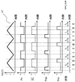
図2に電圧指令値セレクタ(19)が作動し、全相とも所定の電圧指令値(V*)に変更された場合の駆動パルスを図示する。図2では、電圧指令値(V*)が略零、つまり、鋸波形状等の搬送波の中央値の場合を示している。しかし、本実施例では、電圧指令値(V*)を略零に限るものではなく、実装上の事由などにより任意の値とすることができる。
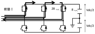
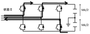
全相同一の電圧指令値(V*)によって駆動された場合、半導体スイッチングモジュール群の導通,非導通状態は3つの状態(I,II,III)のいずれかの状態となり、状態I,状態II,状態III,状態IIの順に循環的に状態遷移を繰り返す動作をするように駆動パルスが生成される。電圧指令値(V*)が略鋸波形状等の搬送波の中央値であれば、状態Iと状態IIIの継続時間が等しくなり、電圧指令値(V*)が前述の中央値より大きい場合、状態Iの継続時間が状態IIIの継続時間より長くなり、電圧指令値(V*)が前述の中央値より小さい場合、状態Iの継続時間が状態IIIの継続時間より短くなる。
状態I,状態II,状態IIIのそれぞれ場合の電流経路は、例えば、U相,V相を流れる電流が巻線型二次励磁発電機(2)から電力変換器(7)の方向へ流れ、W相を流れる電流が前述の方向と逆向きに流れる場合、図3(状態I),図4(状態II),図5(状態III)となる。尚、図3~5では、半導体スイッチングモジュールの導通状態,非導通状態を模式的に示すため、簡易なスイッチで図示している。
全相同一の電圧指令値(V*)によって駆動パルスを生成することで、平滑コンデンサ(8)を充電するように電流が流れ、過電圧状態に陥る状態II(図4)の他に、全相同一電圧を出力することで巻線型二次励磁発電機(2)の回転子巻線(3)を疑似的に短絡し、平滑コンデンサ(8)を回転子巻線(3)から電気的に隠蔽する状態I(図3)及び状態III(図5)とすることができる。これにより平滑コンデンサ(8)への系統事故による過電流の流入を抑制することができ、平滑コンデンサ(8)の過電圧を抑制することが可能となる。さらに、抵抗チョッパ回路などで構成されるエネルギー消費器(9)で消費エネルギーを最小化することができる。これにより、電力変換器(7)内部で発生する発熱を抑制することができるため、冷却機構の簡素化を図ること電力変換器(7)の小型化を図ることができる。
さらに、全相同一の電圧指令(V*)によって駆動パルスを生成することで、状態I(図3)及び状態III(図5)で、巻線型二次励磁発電機(2)の回転子巻線(3)を擬似的に短絡させるため、従来、巻線型二次励磁発電機(2)と電力変換器(7)の間に設けられてきたクローバ回路(例えば特許文献1の810)と同様の効果を得ることができる。これにより、2つの電力変換器を互いの直流端子に平滑コンデンサを共有して接続し、双方向の交流入出力を可能とした電力変換器を、2つの巻線型二次励磁発電機の回転子を同軸に連結した回転子に実装し、前述の2つの電力変換器の交流端子を2つの巻線型二次励磁発電機の回転子巻線に各々接続することで、巻線型二次励磁発電機のブラシとスリップリングを不要とする方式のように、実装及び設置スペースが限られる用途において、クローバ回路レス化を図ることができる。
また、電圧指令の出力するに際して、電圧低下検出器が電圧の低下を検出した場合に、初めに、電力変換器における最も高い電圧を出力する交流出力と、最も低い電圧を出力する交流出力とが同一になる様に電圧指令を出力し、段階的に指令を出力しても良い。或いは、電圧低下検出器が電圧の低下を検出した場合に、電力変換器における各電圧の交流出力が同一になる様に電圧指令を一度に出力することも可能である。いずれにおいても、電力変換器の畜電器に流入するエネルギーを抑制することが可能である。
本実施例に係る二次励磁可変速発電システムを風力発電システムに適用した例を図6に示す。本実施例では、実施例1と比較して、デットタイム回路(21)が遅延時間を変更可能なデットタイム回路(21)に変更され、さらに、デットタイムセレクタ(25)が追加される。以下、実施例1と重複する部分の説明は省略する。
本実施例は、デットタイムセレクタ(25)が、電圧低下検出器(24)の電圧低下発生有無(LV)を入力として、電圧低下が発生していない場合(LV=1)に、実施例1で詳述した通常の発電動作における平滑コンデンサ(8)の短絡を防止するデットタイム時間t0を出力し、電圧低下が発生している場合(LV=0)に、t0≦t1となる所定のデットタイム時間t1を出力し、遅延時間を変更可能なデットタイム回路(21)がデットタイムセレクタ(25)からのデットタイム時間入力に従って、半導体スイッチングモジュールの駆動パルスに、(半導体スイッチングモジュール群を)同時に非導通状態とする時間幅(デットタイム)を付加することを特徴とする。即ち、電力変換器において、異なる電位間を接続し、かつ互いに直列接続される半導体スイッチングモジュール群を考えた時に、電圧低下検出器が電圧の低下を検出した場合におけるこの半導体スイッチングモジュール群間のデットタイムt1を、低下検出器が電圧の低下を検出されない場合におけるデットタイムt0よりも長くする。
前述のデットタイムセレクタ(25)に設定する電圧低下時のデットタイム時間t1の大小によって、全相同一の電圧指令値(V*)によって駆動された場合に半導体スイッチングモジュール群が採り得る3つの導通,非導通状態(I,II,III)のうち、状態IIの継続時間の比率を大きくすることができる(図7)。
これにより、通常のデットタイム時間t0で動作する場合に比べて、平滑コンデンサ(8)への系統事故による過電流の流入を調整することができる。本発明の機能が発現している場合の、電力変換器(7)の発熱と、エネルギー消費器(9)の発熱を調整することが可能となる。
本実施例に係る二次励磁可変速発電システムを風力発電システムに適用した例を図8に示す。本実施例では、実施例2と比較して、電力変換器(7)部とエネルギー消費器(9)にそれぞれ温度検出器(26,27)が追加され、前述の温度検出器からの温度検出値(Temp0,Temp1)を電圧低下検出器(24)の追加入力信号とし、電圧低下検出器(24)は電圧低下と判定した場合に、前述の温度検出値(Temp0,Temp1)に基づいて、電圧指令値(V*)及びデットタイム時間(t1)を算出し、電圧低下電圧指令値セレクタ(19)及びデットタイムセレクタ(25)に出力する。また、電圧指令値セレクタ(19)及びデットタイムセレクタ(25)は電圧低下検出器からの電圧指令値(V*)及びデットタイム時間(t1)を、それぞれ追加の入力とする点が異なる。以下、実施例2と重複する部分の説明は省略する。
電力変換器(7)部に備わる温度検出器(26)が出力する温度検出値(Temp0)は、少なくとも正極側の半導体スイッチングモジュールの温度検出値と負極側の半導体スイッチングモジュールの温度検出値を含むものである。例えば、2レベル電力変換器であれば、前述の正極側と負極側の2つの温度検出値を最低限含むものであり、U相,V相,W相の相毎の半導体スイッチングモジュールのそれぞれ正極側及び負極側の温度検出値、つまり、6つの温度検出値であっても良い。また、3レベル電力変換器等、出力できる電圧が複数ある回路構成では、出力する電圧の数、つまりレベル数分の温度検出値を含めても良く、さらに、相毎に温度を検出しても良い。その回路構成に応じて温度検出値の数を変更することは、本発明の効果の発現に影響しない。
エネルギー消費器(9)に備わる温度検出器(27)が出力する温度検出値(Temp1)は、少なくともエネルギー消費器を構成する半導体スイッチングモジュール及び抵抗体の温度検出値を含むものである。
本実施例の電圧低下検出器(24)は、電圧低下と判定した場合に、エネルギー消費器(9)の温度検出値(Temp1)が所定の値より小さい場合に、大きなt1(≧t0)を出力し大きくし、温度検出値(Temp1)が所定の値より大きい場合に、小さなt1(≧t0)を出力し、また、電力変換器(7)の温度検出値(Temp0)に対して、例えば電力変換器(7)が2レベル電力変換器の場合、正極側の半導体スイッチングモジュールの温度と負極側の半導体スイッチングモジュールの温度を比較し、正極側の半導体スイッチングモジュールの温度が高い場合には、鋸波形状等の搬送波の中央値以下の電圧指令値(V*)を出力し、逆に、負極側の半導体スイッチングモジュールの温度が高い場合には、鋸波形状等の搬送波の中央値以上の電圧指令値(V*)を出力することを特徴とする。
本実施例では、電力変換器の異なる電位に接続される半導体スイッチングモジュールの温度を少なくとも区別して検出する。そして、電圧低下検出器(24)が電圧の低下を検出した場合に、同じ電位に接続される半導体スイッチングモジュール群のうち、半導体スイッチングモジュールの中で相対的に温度が高い半導体スイッチングモジュールが含まれる半導体スイッチングモジュール群の電流導通時間を、他の電位に接続される半導体スイッチングモジュール群の電流導通時間よりも短くするように、電圧指令値を出力する様にできる。更に、半導体スイッチングモジュールの温度と、エネルギー消費器(9)の温度を用いて、半導体スイッチングモジュールの駆動パルスを決定することが出来る。
また本実施例では、エネルギー消費器(9)の温度を検出しており、電圧低下検出器(24)が電圧の低下を検出した場合に、電力変換器の異なる電位間を接続し、かつ互いに直列接続される半導体スイッチングモジュール群間のデットタイムを、検出された温度を用いて決定することができる。
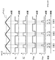
前述のデットタイムセレクタ(25)に設定する電圧低下時のデットタイム時間t1の大小によって、全相同一の電圧指令値(V*)によって駆動された場合に半導体スイッチングモジュール群が採り得る3つの導通,非導通状態(I,II,III)のうち、状態IIの継続時間の比率を大きくすることができ、さらに、電圧指令値(V*)の大小によって、導通,非導通状態(I,II,III)のうち、状態Iと状態IIIの継続時間の比率を変更することができる。図9に電圧指令値(V*)が搬送波の中央値より大きく、デットタイム時間t1>t0の場合の駆動パルスを図示する。
これにより、平滑コンデンサ(8)への系統事故による過電流の流入調整、及び、正極側と負極側の電流通電時間調整が可能になる。本発明の機能発現により、電力変換器(7)の正極側と負極側及びエネルギー消費器(9)の発熱を調整することが可能となる。
本実施例に係る二次励磁可変速発電システムを風力発電システムに適用した例を図10に示す。本実施例では、実施例1と比較して過電流検出器(23)及びゲートブロック回路(22)が異なる。実施例1と重複する部分の説明は省略する。
本実施例の過電流検出器(23)は、巻線型二次励磁発電機(2)の回転子巻線(3)に流れる電流を検出する電流検出器(13)の電流検出値(Irt)を入力として、3相の電流検出値それぞれ独立にその瞬時値の絶対値が所定の値を超過していることを判定条件として、相毎に過電流の発生有無を判定し、相毎の過電流判定信号(OCu,OCv,OCw)(過電流発生無を1,発生有を0とする)を出力する。ゲートブロック回路(22)は、それぞれ対応する過電流判定信号(OCu,OCv,OCw)が0で入力された相のみ、半導体スイッチングモジュールの動作を抑制する(ゲートブロック動作)。即ち、電力変換器の交流側の電流を相毎に検出する電流検出器(13)による相毎の電流検出値の絶対値を所定値と比較することで、交流側に過電流が生じているかを過電流検出器(23)等で判別し、過電流が生じていない場合に、電力変換器の半導体スイッチングモジュールの相毎のスイッチング動作を、論理回路部等を用いて許可する。
過電流判定及びゲートブロック動作を相毎とすることで、系統事故が継続中で過電流が十分に減衰していない場合でも、U相,V相,W相それぞれを流れる電流の電流振幅に合わせてゲートブロック動作を解除する(過電流判定信号が1の状態)ことができる。3相のうち少なくとも2相のゲートブロックを解除することで、解除された相同士に同一の電圧を出力することができ、巻線型二次励磁発電機(2)の回転子巻線(3)を疑似的に短絡できる。
これにより、3相一括でゲートブロック動作する場合に比べて、系統事故による過電流が継続中であっても、随時2相を擬似的に短絡状態とすることで、早期に、また、断続的に、平滑コンデンサ(8)への系統事故による過電流の流入を抑制することができ、平滑コンデンサ(8)の過電圧を抑制することが可能となる。
《その他の実施形態》
実施例3において、電力変換器(7)及びエネルギー消費器(9)のそれぞれに温度検出器(26,27)を備え、それらの温度検出値(Temp1,Temp1)を用いる実施例を紹介したが、温度を検出することと合わせて、または少なくとも部分的に変えて、駆動パルスと巻線型二次励磁発電機(2)の回転子巻線(3)を流れる電流の大きさ及び向きから、通電する半導体スイッチングモジュールを同定し、導通電流と、半導体スイッチングモジュールの熱抵抗及び比熱から、半導体スイッチングモジュール内の配線接続部の温度を推定しても良い。本発明における「温度の検出」には、「温度の推定」も含まれる。
《その他の実施形態》
実施例3において、電力変換器(7)及びエネルギー消費器(9)のそれぞれに温度検出器(26,27)を備え、それらの温度検出値(Temp1,Temp1)を用いる実施例を紹介したが、温度を検出することと合わせて、または少なくとも部分的に変えて、駆動パルスと巻線型二次励磁発電機(2)の回転子巻線(3)を流れる電流の大きさ及び向きから、通電する半導体スイッチングモジュールを同定し、導通電流と、半導体スイッチングモジュールの熱抵抗及び比熱から、半導体スイッチングモジュール内の配線接続部の温度を推定しても良い。本発明における「温度の検出」には、「温度の推定」も含まれる。
推定した温度に基づいて、電圧指令値(V*)及びデットタイム時間(t1)を決定しても良く、機器を構成する部品の使用環境制約から、それら制約を緩和するように、前述の電圧指令値(V*)及びデットタイム時間(t1)を決定することも可能である。
尚、電力系統(1)の電圧低下時に、3相の電圧出力のうち、少なくとも2相に同一の電圧を出力することで、二次励磁可変速発電システムの巻線型二次励磁発電機(2)の回転子巻線(3)を擬似的に短絡させるものであれば、制御ブロックの詳細な内部演算の差異を問わず、電力変換器(7)に流入する系統事故エネルギーを抑制する効果を得ることを目的したものであり、本発明の範囲に含まれる。
1 電力系統
2 巻線型二次励磁発電機
3 回転子巻線
4 固定子巻線
5 回転軸もしくはシャフト
6 翼もしくはブレード
7,7’ 電力変換器
8 平滑コンデンサ
9 エネルギー消費器
10 電力系統の電圧検出器
11 電力系統の電流検出器
12 巻線型二次励磁発電機の固定子線間電圧検出器
13 巻線型二次励磁発電機の回転子相電流検出器
14 平滑コンデンサの正極-負極間電圧検出器
15 電力変換器制御器
16 風車制御器
17 DQ電圧指令値演算器
18 DQ/3相座標変換器
19 電圧指令値セレクタ
20 PWMパルス発生器
21 デットタイム回路
22 ゲートブロック回路
23 過電流検出器
24 電圧低下検出器
25 デットタイムセレクタ
26 半導体スイッチングモジュールの温度検出器
27 エネルギー消費器の温度検出器
28 半導体スイッチングモジュール
29 電力系統に接続する電力変換器側の電流検出器
V 電力系統の電圧検出値
I 電力系統の電流検出値
Vst 巻線型二次励磁発電機の固定子電圧検出値
Irt 巻線型二次励磁発電機の回転子電流検出値
P* 有効電力指令
Q* 無効電力指令
Vdc 直流電圧検出値
PCHP エネルギー消費器の動作指令
slip すべり位相
Vd* d軸電圧指令値
Vq q軸電圧指令値
Vx* x相電圧指令値(x=u,v,w)
Px x相駆動パルス(x=u,v,w)
Pxp x相正極側半導体モジュール駆動パルス(x=u,v,w)
Pxn x相負極側半導体モジュール駆動パルス(x=u,v,w)
OC 過電流判定値
OCx x相過電流判定値(x=u,v,w)
LV 電圧低下判定値
Temp0 半導体スイッチングモジュールの温度検出値
Temp1 エネルギー消費器の温度検出値
t0 発電運転時のデットタイム時間幅
t1 電圧低下中のデットタイム時間幅
rot 回転速度検出値
2 巻線型二次励磁発電機
3 回転子巻線
4 固定子巻線
5 回転軸もしくはシャフト
6 翼もしくはブレード
7,7’ 電力変換器
8 平滑コンデンサ
9 エネルギー消費器
10 電力系統の電圧検出器
11 電力系統の電流検出器
12 巻線型二次励磁発電機の固定子線間電圧検出器
13 巻線型二次励磁発電機の回転子相電流検出器
14 平滑コンデンサの正極-負極間電圧検出器
15 電力変換器制御器
16 風車制御器
17 DQ電圧指令値演算器
18 DQ/3相座標変換器
19 電圧指令値セレクタ
20 PWMパルス発生器
21 デットタイム回路
22 ゲートブロック回路
23 過電流検出器
24 電圧低下検出器
25 デットタイムセレクタ
26 半導体スイッチングモジュールの温度検出器
27 エネルギー消費器の温度検出器
28 半導体スイッチングモジュール
29 電力系統に接続する電力変換器側の電流検出器
V 電力系統の電圧検出値
I 電力系統の電流検出値
Vst 巻線型二次励磁発電機の固定子電圧検出値
Irt 巻線型二次励磁発電機の回転子電流検出値
P* 有効電力指令
Q* 無効電力指令
Vdc 直流電圧検出値
PCHP エネルギー消費器の動作指令
slip すべり位相
Vd* d軸電圧指令値
Vq q軸電圧指令値
Vx* x相電圧指令値(x=u,v,w)
Px x相駆動パルス(x=u,v,w)
Pxp x相正極側半導体モジュール駆動パルス(x=u,v,w)
Pxn x相負極側半導体モジュール駆動パルス(x=u,v,w)
OC 過電流判定値
OCx x相過電流判定値(x=u,v,w)
LV 電圧低下判定値
Temp0 半導体スイッチングモジュールの温度検出値
Temp1 エネルギー消費器の温度検出値
t0 発電運転時のデットタイム時間幅
t1 電圧低下中のデットタイム時間幅
rot 回転速度検出値
Claims (10)
- 各相の固定子巻線を有する固定子及び、前記固定子と間隙を設けて設置されると共に各相の回転子巻線を有する回転子を備える回転機と、
前記回転子巻線に接続され、直流と交流を切り替える電力変換器と、
前記電力変換器の直流側に接続される蓄電器と、
少なくとも前記回転子巻線に印加される電圧、前記固定子巻線に印加される電圧または前記固定子巻線に接続される電力系統の電圧のいずれかの電圧を検出する電圧検出器、またはいずれかの前記電圧を演算により求める演算器と、
少なくともいずれかの前記電圧の低下を検出する電圧低下検出器と、を備え、
前記電圧低下検出器が電圧の低下を検出した場合に、前記電力変換器に対し、各相同一の電圧指令を出力することを特徴とする回転電機システム。 - 請求項1に記載の回転電機システムであって、前記電圧低下検出器が電圧の低下を検出した場合に、前記電力変換器における最も高い電圧を出力する交流出力と、最も低い電圧を出力する交流出力とが同一になる様に電圧指令を出力することを特徴とする回転電機システム。
- 請求項1に記載の回転電機システムであって、前記電圧低下検出器が電圧の低下を検出した場合に、前記電力変換器における各電圧の交流出力が同一になる様に電圧指令を出力することを特徴とする回転電機システム。
- 請求項1に記載の回転電機システムであって、更に前記電力変換器は異なる電位間を接続し、かつ互いに直列接続される半導体スイッチングモジュール群を備え、
前記電圧低下検出器が電圧の低下を検出した場合における前記半導体スイッチングモジュール群間のデットタイムを、前記電圧低下検出器が電圧の低下を検出されない場合における前記デットタイムよりも長くすることを特徴とする回転電機システム。 - 請求項1ないし4のいずれか1項に記載の回転電機システムであって、
前記電力変換器の異なる電位に接続される半導体スイッチングモジュールの温度を少なくとも区別して検出し、
前記電圧低下検出器が電圧の低下を検出した場合に、同じ電位に接続される半導体スイッチングモジュール群のうち、前記半導体スイッチングモジュールの中で相対的に温度が高い半導体スイッチングモジュールが含まれる半導体スイッチングモジュール群の電流導通時間を、他の電位に接続される半導体スイッチングモジュール群の電流導通時間よりも短くするように、電圧指令値を出力することを特徴とする回転電機システム。 - 請求項1ないし5のいずれか1項に記載の回転電機システムであって、更に前記蓄電器に蓄えられる電気的エネルギーを消費する消費器を備え、
該消費器の温度を検出し、
前記電圧低下検出器が電圧の低下を検出した場合に、前記電力変換器の異なる電位間を接続し、かつ互いに直列接続される半導体スイッチングモジュール群間のデットタイムを、検出された温度を用いて決定することを特徴とする回転電機システム - 請求項5に記載の回転電機システムであって、更に前記蓄電器に蓄えられる電気的エネルギーを消費する消費器を備え、
該消費器の温度を検出し、
前記半導体スイッチングモジュールの温度と、前記消費器の温度を用いて、前記半導体スイッチングモジュールの駆動パルスを決定することを特徴とする回転電機システム。 - 請求項1ないし7のいずれか1項に記載の回転電機システムであって、更に前記電力変換器の交流側の電流を相毎に検出する電流検出器を備え、
相毎の電流検出値の絶対値を所定値と比較して、交流側に過電流が生じているかを判別し、
過電流が生じていない場合に、前記電力変換器の半導体スイッチングモジュールの相毎のスイッチング動作を許可することを特徴とする回転電機システム。 - 請求項8に記載の回転電機システムであって、
更に前記過電流の判別を行う過電流検出器と、
過電流が生じていない場合に、前記電力変換器の半導体スイッチングモジュールの相毎のスイッチング動作を許可する論理回路部とを備えることを特徴とする回転電機システム。 - 各相の固定子巻線を有する固定子及び、前記固定子と間隙を設けて設置されると共に各相の回転子巻線を有する回転子を備える回転機と、
前記回転子巻線に接続され、直流と交流を切り替える電力変換器と、
前記電力変換器の直流側に接続される蓄電器とを備える回転電機システムの制御方法であって、
少なくとも前記回転子巻線に印加される電圧、前記固定子巻線に印加される電圧または前記固定子巻線に接続される電力系統の電圧のいずれかの電圧を検出または演算し、
少なくともいずれかの前記電圧の低下を検出し、
電圧の低下を検出した場合に、前記電力変換器に対し、各相同一の電圧指令を出力することを特徴とする回転電機システムの制御方法。
Priority Applications (1)
| Application Number | Priority Date | Filing Date | Title |
|---|---|---|---|
| PCT/JP2014/065030 WO2015186232A1 (ja) | 2014-06-06 | 2014-06-06 | 回転電機システムまたは回転電機システムの制御方法 |
Applications Claiming Priority (1)
| Application Number | Priority Date | Filing Date | Title |
|---|---|---|---|
| PCT/JP2014/065030 WO2015186232A1 (ja) | 2014-06-06 | 2014-06-06 | 回転電機システムまたは回転電機システムの制御方法 |
Publications (1)
| Publication Number | Publication Date |
|---|---|
| WO2015186232A1 true WO2015186232A1 (ja) | 2015-12-10 |
Family
ID=54766327
Family Applications (1)
| Application Number | Title | Priority Date | Filing Date |
|---|---|---|---|
| PCT/JP2014/065030 Ceased WO2015186232A1 (ja) | 2014-06-06 | 2014-06-06 | 回転電機システムまたは回転電機システムの制御方法 |
Country Status (1)
| Country | Link |
|---|---|
| WO (1) | WO2015186232A1 (ja) |
Cited By (2)
| Publication number | Priority date | Publication date | Assignee | Title |
|---|---|---|---|---|
| WO2020089972A1 (ja) | 2018-10-29 | 2020-05-07 | 東芝三菱電機産業システム株式会社 | 風力発電システムおよび電力変換装置 |
| WO2020230343A1 (ja) * | 2019-05-16 | 2020-11-19 | 日立三菱水力株式会社 | 二次励磁発電電動装置 |
Citations (3)
| Publication number | Priority date | Publication date | Assignee | Title |
|---|---|---|---|---|
| JP2006352741A (ja) * | 2005-06-20 | 2006-12-28 | Nec Electronics Corp | デッドタイム制御回路 |
| JP2012032359A (ja) * | 2010-08-03 | 2012-02-16 | Honda Motor Co Ltd | 配線状態検出回路及び制御装置 |
| JP2013212026A (ja) * | 2012-03-30 | 2013-10-10 | Daihen Corp | 保護制御装置 |
-
2014
- 2014-06-06 WO PCT/JP2014/065030 patent/WO2015186232A1/ja not_active Ceased
Patent Citations (3)
| Publication number | Priority date | Publication date | Assignee | Title |
|---|---|---|---|---|
| JP2006352741A (ja) * | 2005-06-20 | 2006-12-28 | Nec Electronics Corp | デッドタイム制御回路 |
| JP2012032359A (ja) * | 2010-08-03 | 2012-02-16 | Honda Motor Co Ltd | 配線状態検出回路及び制御装置 |
| JP2013212026A (ja) * | 2012-03-30 | 2013-10-10 | Daihen Corp | 保護制御装置 |
Cited By (7)
| Publication number | Priority date | Publication date | Assignee | Title |
|---|---|---|---|---|
| WO2020089972A1 (ja) | 2018-10-29 | 2020-05-07 | 東芝三菱電機産業システム株式会社 | 風力発電システムおよび電力変換装置 |
| US11764585B2 (en) | 2018-10-29 | 2023-09-19 | Toshiba Mitsubishi-Electric Industrial Systems Corporation | Wind power generation system and power conversion apparatus |
| WO2020230343A1 (ja) * | 2019-05-16 | 2020-11-19 | 日立三菱水力株式会社 | 二次励磁発電電動装置 |
| JPWO2020230343A1 (ja) * | 2019-05-16 | 2020-11-19 | ||
| CN113826319A (zh) * | 2019-05-16 | 2021-12-21 | 日立三菱水力株式会社 | 二次励磁发电电动装置 |
| JP7153796B2 (ja) | 2019-05-16 | 2022-10-14 | 日立三菱水力株式会社 | 二次励磁発電電動装置 |
| US11942873B2 (en) | 2019-05-16 | 2024-03-26 | Hitachi Mitsubishi Hydro Corporation | Secondary magnetic excitation generator-motor device |
Similar Documents
| Publication | Publication Date | Title |
|---|---|---|
| Ko et al. | Fault diagnosis of three-parallel voltage-source converter for a high-power wind turbine | |
| CA2914293C (en) | Systems and methods for increasing wind turbine power output | |
| EP3629440B1 (en) | System and method for controlling uninterruptible power supply of electrical power systems | |
| US20120217749A1 (en) | Control system for wind farms with aerogenerations provided with modular converters | |
| US9362859B2 (en) | System and method for controlling switching elements within a single-phase bridge circuit | |
| JP6680957B2 (ja) | 交流スイッチならびにそれを備える無停電電源装置および瞬低補償装置 | |
| US10186995B2 (en) | Rotating switching strategy for power converters | |
| CN105098825A (zh) | 换流器及其操作方法 | |
| EP3050189A1 (en) | Power conversion system with re-configurable power flow | |
| US9455568B2 (en) | Energy storage system for renewable energy source | |
| Yeh et al. | Induction motor-drive systems with fault tolerant inverter-motor capabilities | |
| JP2017038435A (ja) | 電力変換装置 | |
| JP6134787B2 (ja) | 回転電機システムまたは風力発電システム | |
| CN102804592B (zh) | 风能设备的叶片调整系统的紧急调整装置 | |
| WO2015186232A1 (ja) | 回転電機システムまたは回転電機システムの制御方法 | |
| JP2017163659A (ja) | 風力発電システム | |
| WO2019208728A1 (ja) | 水力発電系統連系システム | |
| CN104584360A (zh) | 用于检测电机的孤岛并且保护电机的系统和方法 | |
| JP2021175200A (ja) | 電力変換装置 | |
| JP2016167900A (ja) | 風力発電システムの制御装置 | |
| JP2019054641A (ja) | 電力変換装置 | |
| TWI505625B (zh) | Power conversion system and its control method | |
| JP6453107B2 (ja) | 発電システム | |
| JP2019193512A (ja) | 水力発電系統連系システム | |
| JP2019047598A (ja) | 電力制御装置、電力制御装置の制御方法 |
Legal Events
| Date | Code | Title | Description |
|---|---|---|---|
| 121 | Ep: the epo has been informed by wipo that ep was designated in this application |
Ref document number: 14893811 Country of ref document: EP Kind code of ref document: A1 |
|
| NENP | Non-entry into the national phase |
Ref country code: DE |
|
| 122 | Ep: pct application non-entry in european phase |
Ref document number: 14893811 Country of ref document: EP Kind code of ref document: A1 |
|
| NENP | Non-entry into the national phase |
Ref country code: JP |