WO2015182057A1 - Cycle de réfrigération d'éjecteur - Google Patents
Cycle de réfrigération d'éjecteur Download PDFInfo
- Publication number
- WO2015182057A1 WO2015182057A1 PCT/JP2015/002488 JP2015002488W WO2015182057A1 WO 2015182057 A1 WO2015182057 A1 WO 2015182057A1 JP 2015002488 W JP2015002488 W JP 2015002488W WO 2015182057 A1 WO2015182057 A1 WO 2015182057A1
- Authority
- WO
- WIPO (PCT)
- Prior art keywords
- refrigerant
- pressure
- evaporator
- stage
- ejector
- Prior art date
Links
Images


Classifications
-
- F—MECHANICAL ENGINEERING; LIGHTING; HEATING; WEAPONS; BLASTING
- F25—REFRIGERATION OR COOLING; COMBINED HEATING AND REFRIGERATION SYSTEMS; HEAT PUMP SYSTEMS; MANUFACTURE OR STORAGE OF ICE; LIQUEFACTION SOLIDIFICATION OF GASES
- F25B—REFRIGERATION MACHINES, PLANTS OR SYSTEMS; COMBINED HEATING AND REFRIGERATION SYSTEMS; HEAT PUMP SYSTEMS
- F25B5/00—Compression machines, plants or systems, with several evaporator circuits, e.g. for varying refrigerating capacity
- F25B5/02—Compression machines, plants or systems, with several evaporator circuits, e.g. for varying refrigerating capacity arranged in parallel
-
- F—MECHANICAL ENGINEERING; LIGHTING; HEATING; WEAPONS; BLASTING
- F25—REFRIGERATION OR COOLING; COMBINED HEATING AND REFRIGERATION SYSTEMS; HEAT PUMP SYSTEMS; MANUFACTURE OR STORAGE OF ICE; LIQUEFACTION SOLIDIFICATION OF GASES
- F25B—REFRIGERATION MACHINES, PLANTS OR SYSTEMS; COMBINED HEATING AND REFRIGERATION SYSTEMS; HEAT PUMP SYSTEMS
- F25B1/00—Compression machines, plants or systems with non-reversible cycle
- F25B1/06—Compression machines, plants or systems with non-reversible cycle with compressor of jet type, e.g. using liquid under pressure
-
- F—MECHANICAL ENGINEERING; LIGHTING; HEATING; WEAPONS; BLASTING
- F25—REFRIGERATION OR COOLING; COMBINED HEATING AND REFRIGERATION SYSTEMS; HEAT PUMP SYSTEMS; MANUFACTURE OR STORAGE OF ICE; LIQUEFACTION SOLIDIFICATION OF GASES
- F25B—REFRIGERATION MACHINES, PLANTS OR SYSTEMS; COMBINED HEATING AND REFRIGERATION SYSTEMS; HEAT PUMP SYSTEMS
- F25B40/00—Subcoolers, desuperheaters or superheaters
-
- F—MECHANICAL ENGINEERING; LIGHTING; HEATING; WEAPONS; BLASTING
- F25—REFRIGERATION OR COOLING; COMBINED HEATING AND REFRIGERATION SYSTEMS; HEAT PUMP SYSTEMS; MANUFACTURE OR STORAGE OF ICE; LIQUEFACTION SOLIDIFICATION OF GASES
- F25B—REFRIGERATION MACHINES, PLANTS OR SYSTEMS; COMBINED HEATING AND REFRIGERATION SYSTEMS; HEAT PUMP SYSTEMS
- F25B41/00—Fluid-circulation arrangements
-
- F—MECHANICAL ENGINEERING; LIGHTING; HEATING; WEAPONS; BLASTING
- F25—REFRIGERATION OR COOLING; COMBINED HEATING AND REFRIGERATION SYSTEMS; HEAT PUMP SYSTEMS; MANUFACTURE OR STORAGE OF ICE; LIQUEFACTION SOLIDIFICATION OF GASES
- F25B—REFRIGERATION MACHINES, PLANTS OR SYSTEMS; COMBINED HEATING AND REFRIGERATION SYSTEMS; HEAT PUMP SYSTEMS
- F25B2341/00—Details of ejectors not being used as compression device; Details of flow restrictors or expansion valves
- F25B2341/001—Ejectors not being used as compression device
- F25B2341/0011—Ejectors with the cooled primary flow at reduced or low pressure
Definitions
- the present disclosure relates to an ejector-type refrigeration cycle including a plurality of evaporators that evaporate a refrigerant in different temperature zones.
- an ejector-type refrigeration cycle which is a vapor compression refrigeration cycle apparatus including an ejector, is known.
- the refrigerant that has flowed out of the evaporator due to the suction action of the high-speed jet refrigerant injected from the nozzle portion of the ejector is sucked from the refrigerant suction port of the ejector, and the diffuser portion (pressure booster) of the ejector
- the pressure of the mixed refrigerant of the injection refrigerant and the suction refrigerant is increased in step, and the mixed refrigerant whose pressure is increased in the diffuser section is sucked into the compressor.
- the power consumption of the compressor is reduced and the coefficient of performance (COP) of the cycle is reduced compared to a normal refrigeration cycle apparatus in which the refrigerant evaporation pressure in the evaporator and the suction refrigerant pressure in the compressor are substantially equal. ) Can be improved.
- Patent Document 1 includes two evaporators as this type of ejector-type refrigeration cycle, and the refrigerant flowing out from one evaporator (first evaporator) flows into the nozzle portion of the ejector and the other is evaporated.
- first evaporator the refrigerant flowing out from one evaporator
- coolant which flowed out from the container (2nd evaporator) from the refrigerant
- the refrigerant evaporation temperature in the first evaporator and the refrigerant evaporation temperature in the second evaporator are in different temperature zones. Therefore, in Patent Document 1, this ejector refrigeration cycle is applied to a cold insulation device, and the first evaporator and the second evaporator are arranged in different cold insulation chambers (cooling target spaces), and the respective cold insulation chambers are different. The temperature can be kept cool.
- required of each evaporator is different.
- the cooling capacity is defined by the integrated value of the enthalpy difference obtained by subtracting the enthalpy of the refrigerant on the inlet side of the evaporator from the enthalpy of the refrigerant on the outlet side of the evaporator and the refrigerant flow rate (mass flow rate) flowing through the evaporator.
- the refrigerant is sucked by the sucking action of the jetted refrigerant, thereby recovering the speed energy loss when the refrigerant is decompressed at the nozzle portion. Then, the mixed refrigerant is pressurized by converting the velocity energy of the mixed refrigerant of the injected refrigerant and the suction refrigerant into pressure energy in the diffuser section.
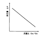
- the flow rate ratio Ge / Gn is reduced, so that the flow rate of the refrigerant flowing through the second evaporator decreases, so that the cooling capacity exhibited by the second evaporator is the cooling capacity exhibited by the first evaporator. It will be lower than.
- the flow ratio Ge / Gn is increased, the cooling capacity exhibited by the second evaporator can be brought closer to the cooling capacity exhibited by the first evaporator, but the pressure increase amount ⁇ P decreases. Therefore, it becomes difficult to obtain the COP improvement effect.
- the present disclosure provides a first feature that in a ejector refrigeration cycle including a plurality of evaporators that evaporate a refrigerant in different temperature zones, the cooling capacity exhibited by each evaporator can be adjusted. Objective.
- a second object of the present disclosure is to bring the cooling capacity exhibited by each evaporator closer in an ejector refrigeration cycle including a plurality of evaporators that evaporate a refrigerant in different temperature zones.
- An ejector-type refrigeration cycle includes a compressor that compresses and discharges a refrigerant, a radiator that dissipates heat from the refrigerant discharged from the compressor, and a first that depressurizes refrigerant that flows out of the radiator.
- a decompressor and a second decompressor a first evaporator that evaporates the refrigerant decompressed by the first decompressor, a second evaporator that evaporates the refrigerant decompressed by the second decompressor, and the first evaporation Refrigerant sucked from the refrigerant suction port by the suction action of the high-speed jet refrigerant jetted from the nozzle part that decompresses the refrigerant flowing out of the evaporator, and sucked from the jet refrigerant and the refrigerant suction port And an ejector for mixing and boosting.
- the ejector-type refrigeration cycle includes (i) a refrigerant flow path from the refrigerant outlet side of the radiator to the inlet side of the first decompressor, and a refrigerant flow from the refrigerant outlet side of the radiator to the inlet side of the second decompressor.
- the refrigerant flowing through at least one of the refrigerant flow paths is a high-pressure refrigerant
- the refrigerant flowing through the refrigerant flow path from the refrigerant outlet side of the first evaporator to the inlet side of the nozzle portion is the high-stage low pressure
- the refrigerant flowing through the refrigerant flow path from the refrigerant outlet side of the second evaporator to the refrigerant suction port is a low-stage low-pressure refrigerant
- the high-stage low-pressure refrigerant and the low-stage low-pressure refrigerant An internal heat exchanger for exchanging heat between any one of them and the high-pressure refrigerant is provided.
- the refrigerant evaporation temperature in the second evaporator is set. It can be set as the temperature range lower than the refrigerant
- the ejector refrigeration cycle includes an internal heat exchanger that exchanges heat between either the high-stage low-pressure refrigerant or the low-stage low-pressure refrigerant and the high-pressure refrigerant.
- an enthalpy difference obtained by subtracting the enthalpy of the inlet side refrigerant of each evaporator from the enthalpy of the outlet side refrigerant of each evaporator (hereinafter simply referred to as an inlet / outlet enthalpy difference in each evaporator), or a nozzle. It is possible to increase the enthalpy of the refrigerant flowing into the section, and the cooling capacity exhibited by each evaporator can be adjusted.
- an ejector-type refrigeration cycle includes a branch part that branches the flow of refrigerant that has flowed out of a radiator, and the inlet side of the first decompression device is connected to one refrigerant outlet of the branch part.
- the other refrigerant outlet is connected to the inlet side of the second decompression device, and the internal heat exchanger includes a low-stage low-pressure refrigerant and the other refrigerant outlet of the branch portion to the inlet side of the second decompression device. Heat exchange may be performed with the high-pressure refrigerant flowing through the refrigerant flow path.
- the internal heat exchanger can cool the high-pressure refrigerant flowing through the refrigerant flow path from the other refrigerant outlet of the branch portion to the inlet side of the second decompression device, the second evaporator The entrance and exit enthalpy difference at can be expanded.
- the ejector refrigeration cycle includes a branch portion that branches the flow of the refrigerant that has flowed out of the radiator, and the inlet side of the first decompression device is connected to one refrigerant outlet of the branch portion.
- the other refrigerant outlet is connected to the inlet side of the second decompression device, and the internal heat exchanger has a high-stage low-pressure refrigerant and the other refrigerant outlet of the branch portion to the inlet side of the second decompression device. Heat exchange may be performed with the high-pressure refrigerant flowing through the refrigerant flow path.
- the cooling capacity exhibited by the first evaporator and the cooling capacity exhibited by the second evaporator can be brought close to each other. Furthermore, the enthalpy of the refrigerant flowing into the nozzle portion of the ejector can be increased by heating the high-stage low-pressure refrigerant in the internal heat exchanger.
- the amount of energy recovered by the ejector can be increased, and the boost amount ⁇ P of the ejector can be increased without reducing the flow rate ratio Ge / Gn.
- the cooling ability exhibited by the first evaporator and the cooling ability exhibited by the second evaporator can be brought close to each other.
- the ejector refrigeration cycle includes a branch portion that branches the flow of the refrigerant that has flowed out of the radiator, and the inlet side of the first decompression device is connected to one refrigerant outlet of the branch portion.
- the other refrigerant outlet is connected to the inlet side of the second decompression device, and the internal heat exchanger includes a high-stage low-pressure refrigerant and a refrigerant flow path from the refrigerant outlet side of the radiator to the inlet side of the branch portion. It is possible to exchange heat with a high-pressure refrigerant that circulates.
- the cooling capacity exhibited by the first evaporator and the cooling capacity exhibited by the second evaporator are brought close to each other. Can do.
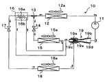
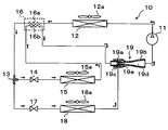
- the ejector refrigeration cycle 10 is applied to a vehicle refrigeration cycle apparatus mounted on a refrigerated vehicle.
- This refrigeration cycle device for a vehicle has a function of cooling indoor air blown into a vehicle compartment in a refrigerated vehicle, and a function of cooling internal blown air sent into a refrigerator arranged in a loading platform of the vehicle Is responsible.
- both the vehicle interior space and the refrigerator internal space are cooling target spaces of the ejector refrigeration cycle 10. Furthermore, in this embodiment, the volume in a vehicle interior and a refrigerator is substantially equivalent, and the cooling capacity required in order to cool each cooling object space is also equivalent.
- the cooling capacity in this embodiment is obtained by subtracting the enthalpy of the outlet side refrigerant of the evaporator provided in the ejector-type refrigeration cycle 10 from the enthalpy of the inlet side refrigerant of the evaporator (entrance / entrance difference). It is defined by an integrated value with the flow rate of refrigerant flowing (mass flow rate).
- the compressor 11 sucks in refrigerant, compresses it, and discharges it.
- the compressor 11 of the present embodiment is an electric compressor configured by housing a fixed capacity type compression mechanism and an electric motor that drives the compression mechanism in one housing.
- compression mechanism various compression mechanisms such as a scroll-type compression mechanism and a vane-type compression mechanism can be adopted. Further, the operation (rotation speed) of the electric motor is controlled by a control signal output from a control device to be described later, and any type of an AC motor and a DC motor may be used.
- a natural refrigerant (specifically, R600a) is adopted as the refrigerant, and the vapor compression subcriticality in which the high-pressure side refrigerant pressure does not exceed the refrigerant critical pressure. It constitutes the refrigeration cycle. Furthermore, refrigeration oil for lubricating the compressor 11 is mixed in the refrigerant, and a part of the refrigeration oil circulates in the cycle together with the refrigerant.
- the refrigerant inlet side of the radiator 12 is connected to the discharge port of the compressor 11.
- the radiator 12 is a heat exchanger for radiating heat by exchanging heat between the refrigerant discharged from the compressor 11 and outside air (outside air) blown by the cooling fan 12a to radiate the high-pressure refrigerant.
- the cooling fan 12a is an electric blower in which the number of rotations (the amount of blown air) is controlled by a control voltage output from the control device.
- the refrigerant outlet side of the radiator 12 is connected to the refrigerant inlet of the branching portion 13 that branches the flow of the refrigerant flowing out of the radiator 12.
- the branch portion 13 is configured by a three-way joint having three inflow / outflow ports, and one of the three inflow / outflow ports is a refrigerant inflow port, and the remaining two are refrigerant outflow ports.
- Such a three-way joint may be formed by joining pipes having different pipe diameters, or may be formed by providing a plurality of refrigerant passages in a metal block or a resin block.
- the inlet side of a high-stage expansion device 14 as a first decompression device is connected to one refrigerant outlet of the branch part 13.
- the high stage side expansion device 14 includes a temperature sensing unit that detects the degree of superheat of the high stage side evaporator 15 outlet side refrigerant based on the temperature and pressure of the high stage side evaporator 15 outlet side refrigerant, This is a temperature type expansion valve that adjusts the throttle passage area by a mechanical mechanism so that the degree of superheat of the refrigerant on the outlet side of the container 15 is within a predetermined reference range.
- the refrigerant inlet side of the high stage evaporator 15 as the first evaporator is connected to the outlet side of the high stage side expansion device 14.
- the high-stage evaporator 15 evaporates the low-pressure refrigerant by exchanging heat between the low-pressure refrigerant decompressed by the high-stage side expansion device 14 and the indoor blown air blown into the vehicle interior from the high-stage blower fan 15a. This is an endothermic heat exchanger that exerts an endothermic effect.
- the high stage side blower fan 15a is an electric blower in which the rotation speed (the amount of blown air) is controlled by a control voltage output from the control device.
- An inlet side of a nozzle portion 19 a of an ejector 19 described later is connected to the refrigerant outlet side of the high stage evaporator 15.
- the other refrigerant outlet of the branch part 13 is connected to the inlet side of the high-pressure side refrigerant passage 16a of the internal heat exchanger 16.
- the internal heat exchanger 16 of the present embodiment has a function of exchanging heat between the high-pressure refrigerant that has flowed out from the other refrigerant outlet of the branch portion 13 and the low-stage low-pressure refrigerant that has flowed out from the low-stage evaporator 18 described later. Fulfill.
- the inlet side of the low-stage expansion device 17 as the second decompression device is connected to the outlet side of the high-pressure side refrigerant passage 16a of the internal heat exchanger 16.
- the low-stage side throttle device 17 is a fixed throttle with a fixed throttle opening, and specifically, a nozzle, an orifice, a capillary tube, or the like can be adopted.
- the refrigerant inlet side of the low stage evaporator 18 as the second evaporator is connected to the outlet side of the low stage expansion device 17.
- the low-stage evaporator 18 exchanges heat between the low-pressure refrigerant decompressed by the low-stage side expansion device 17 and the internal blown air circulated into the refrigerator from the low-stage blower fan 18a.
- An endothermic heat exchanger that evaporates the refrigerant and exerts an endothermic effect.
- the basic configuration of the low-stage evaporator 18 is the same as that of the high-stage evaporator 15, and the basic configuration of the low-stage fan 18a is the same as that of the high-stage fan 15a.
- An inlet side of the low-pressure side refrigerant passage 16 b of the internal heat exchanger 16 is connected to the refrigerant outlet side of the low-stage evaporator 18.
- a refrigerant suction port 19c side of an ejector 19 described later is connected to the outlet side of the low-pressure side refrigerant passage 16b.
- the throttle opening degree of the low stage side throttle device 17 of the present embodiment is set to be smaller than the throttle opening degree of the high stage side throttle device 14 during the normal operation of the cycle. Therefore, the refrigerant evaporation pressure (refrigerant evaporation temperature) in the low stage side evaporator 18 is lower than the refrigerant evaporation pressure (refrigerant evaporation temperature) in the high stage side evaporator 15.
- the high stage side throttle device 14 during normal operation of the cycle is set so that the flow rate ratio Ge / Gn of the suction refrigerant flow rate Ge to the injection refrigerant flow rate Gn is within a predetermined reference range of 1 or less.
- the throttle opening degree (flow rate characteristic), the throttle opening degree (flow rate characteristic) of the low stage side throttle device 17, the passage cross-sectional area of each refrigerant passage of the branch portion 13, and the like are determined.
- the injected refrigerant flow rate Gn is a refrigerant flow rate (mass flow rate) flowing into the nozzle portion 19a of the ejector 19 via the high stage side expansion device 14 and the high stage side evaporator 18.
- the suction refrigerant flow rate Ge is a refrigerant flow rate sucked from the refrigerant suction port 19c of the ejector 19 through the high-pressure side refrigerant passage 16a, the low-stage side expansion device 17 and the low-stage side evaporator 18 of the internal heat exchanger 16. (Mass flow rate).
- the injection refrigerant flow rate Gn is the refrigerant flow rate flowing through the high-stage evaporator 15
- the suction refrigerant flow rate Ge is the refrigerant flow rate flowing through the low-stage evaporator 18.
- the ejector 19 functions as a decompression device that depressurizes the refrigerant that has flowed out of the high-stage evaporator 15, and also flows out of the low-stage evaporator 18 by the suction action of the injected refrigerant that is injected at high speed. It functions as a refrigerant circulation section (refrigerant transport section) that sucks (transports) the refrigerant and circulates it in the cycle.
- refrigerant circulation section refrigerant transport section
- the nozzle portion 19a is formed of a substantially cylindrical metal (for example, stainless steel alloy) or the like that gradually tapers in the refrigerant flow direction, and the like in the refrigerant passage (throttle passage) formed inside. It expands under reduced pressure entropy.
- a throat portion (minimum passage area portion) having the smallest passage cross-sectional area is formed, and further, the refrigerant flows from the throat portion toward the refrigerant injection port for injecting the refrigerant.
- a divergent part in which the passage area gradually increases is formed. That is, the nozzle part 19a is configured as a Laval nozzle.
- the nozzle portion 19a is set such that the flow rate of the injected refrigerant injected from the refrigerant injection port is equal to or higher than the sonic speed during normal operation of the ejector refrigeration cycle 10.
- the body portion 19b is formed of a substantially cylindrical metal (for example, aluminum), functions as a fixing member that supports and fixes the nozzle portion 19a therein, and forms an outer shell of the ejector 19. More specifically, the nozzle portion 19a is fixed by press-fitting so as to be housed inside the longitudinal end of the body portion 19b. Therefore, the refrigerant does not leak from the fixed portion (press-fit portion) between the nozzle portion 19a and the body portion 19b.
- a substantially cylindrical metal for example, aluminum
- a refrigerant suction port 19c provided so as to penetrate the inside and outside of the outer peripheral surface of the body portion 19b and communicate with the refrigerant injection port of the nozzle portion 19a is provided in a portion corresponding to the outer peripheral side of the nozzle portion 19a. Is formed.
- the refrigerant suction port 19 c is a through hole that sucks the refrigerant that has flowed out of the low-stage evaporator 18 into the ejector 19 by the suction action of the jet refrigerant that is ejected from the nozzle portion 19 a.
- a suction passage 19e that guides the suction refrigerant sucked from the refrigerant suction port 19c to the refrigerant injection port side of the nozzle portion 19a, and an ejector 19 from the refrigerant suction port 19c through the suction passage 19e.
- a diffuser portion 19d is formed as a boosting portion that mixes and sucks the suction refrigerant and the injection refrigerant that flow into the interior.
- the suction passage 19e is formed in a space between the outer peripheral side around the tapered tip of the nozzle portion 19a and the inner peripheral side of the body portion 19b, and the refrigerant passage area of the suction passage 19e is in the refrigerant flow direction. It is gradually shrinking. Thereby, the flow rate of the suction refrigerant flowing through the suction passage 19e is gradually increased, and the energy loss (mixing loss) when the suction refrigerant and the injection refrigerant are mixed in the diffuser portion 19d is reduced.
- the diffuser portion 19d is disposed so as to be continuous with the outlet of the suction passage 19e, and is formed so that the refrigerant passage area gradually increases.
- the cross-sectional shape of the inner peripheral wall surface of the body portion 19b that forms the diffuser portion 19d of the present embodiment is formed by combining a plurality of curves. And since the degree of spread of the refrigerant passage cross-sectional area of the diffuser portion 19d gradually increases in the refrigerant flow direction and then decreases again, the refrigerant can be increased in an isentropic manner.
- a suction port of the compressor 11 is connected to the outlet side of the diffuser portion 19 d of the ejector 19.
- the compressor 11, the radiator 12, the cooling fan 12a, and the like are housed in one housing and integrally configured as an outdoor unit. Furthermore, the outdoor unit is arranged on the vehicle front side above the refrigerator.
- a control device (not shown) is composed of a well-known microcomputer including a CPU, ROM, RAM, etc. and its peripheral circuits, performs various calculations and processing based on a control program stored in the ROM, and is connected to the output side.
- the operation of various control target devices (the compressor 11, the cooling fan 12a, the high-stage side fan 15a, the low-stage side fan 18a, etc.) is controlled.
- control device includes an inside air temperature sensor that detects the interior temperature of the vehicle, an outside air temperature sensor that detects the outside air temperature, a solar radiation sensor that detects the amount of solar radiation in the interior of the vehicle, and the air temperature of the high-stage evaporator 15
- the first evaporator temperature sensor for detecting the side evaporator temperature
- the second evaporator temperature sensor for detecting the blown air temperature (low stage evaporator temperature) of the low stage evaporator 18, and the refrigerant on the outlet side refrigerant of the radiator 12
- Sensor groups such as an outlet side temperature sensor for detecting temperature, an outlet side pressure sensor for detecting the pressure of the refrigerant on the outlet side of the radiator 12, and an in-chamber temperature sensor for detecting the temperature in the refrigerator are connected, and detection of these sensor groups is performed. A value is entered.
- an operation panel (not shown) disposed near the instrument panel in the front part of the vehicle interior is connected to the input side of the control device, and operation signals from various operation switches provided on the operation panel are input to the control device.
- various operation switches provided on the operation panel there are provided an operation switch for requesting operation or stop of the vehicle refrigeration cycle apparatus, a vehicle interior temperature setting switch for setting the vehicle interior temperature, and the like.
- control device of the present embodiment is configured integrally with a control unit that controls the operation of various control target devices connected to the output side of the control device.
- a configuration (hardware and software) for controlling the operation constitutes a control unit of each control target device.
- operation of the compressor 11 comprises the discharge capability control part.
- the control device operates the electric motor of the compressor 11, the cooling fan 12a, the high stage side fan 15a, the low stage side fan 18a, and the like. Thereby, the compressor 11 sucks the refrigerant, compresses it, and discharges it.
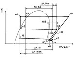
- One refrigerant branched in the branching section 13 flows into the high stage side expansion device 14 and is decompressed in an enthalpy manner (b2 point ⁇ c2 point in FIG. 2).
- the opening degree of the high stage side expansion device 14 is adjusted so that the degree of superheat of the high stage side evaporator 15 outlet side refrigerant (point d2 in FIG. 2) is within a predetermined range.
- the refrigerant decompressed by the high stage side expansion device 14 flows into the high stage side evaporator 15, absorbs heat from the indoor blown air blown by the high stage side blower fan 15a, and evaporates (c2 in FIG. 2). Point ⁇ d2 point). Thereby, the indoor blowing air is cooled.
- the other refrigerant branched at the branch portion 13 flows into the high-pressure side refrigerant passage 16a of the internal heat exchanger 16, and flows out of the low-stage evaporator 18 flowing through the low-pressure side refrigerant passage 16b of the internal heat exchanger 16.
- enthalpy (b2 point ⁇ e2 point in FIG. 2).
- the refrigerant that has flowed out of the high-pressure side refrigerant passage 16a of the internal heat exchanger 16 flows into the low-stage expansion device 17 and is decompressed in an enthalpy manner (point e2 ⁇ point f2 in FIG. 2).
- the pressure of the refrigerant depressurized by the low stage side expansion device 17 is lower than the pressure of the refrigerant depressurized by the high stage side expansion device 14.
- the pressure at point e2 is lower than the pressure at point c2.
- the refrigerant depressurized by the low-stage expansion device 17 flows into the low-stage evaporator 18 and absorbs heat from the internal blown air circulated by the low-stage blower fan 18a to evaporate (FIG. 2). F2 point ⁇ g2 point). As a result, the internal blown air is cooled.
- the enthalpy is raised by exchanging heat with the other refrigerant branched in this way (point g2 ⁇ point h2 in FIG. 2).
- the refrigerant that has flowed out of the high-stage evaporator 15 flows into the nozzle portion 19a of the ejector 19 and is isentropically decompressed and injected (point d2 ⁇ point i2 in FIG. 2). Then, due to the suction action of the injected refrigerant, the low-stage evaporator 18 downstream refrigerant (point h2 in FIG. 2) that has flowed out from the low-pressure refrigerant passage 16b of the internal heat exchanger 16 passes through the refrigerant suction port 19c of the ejector 19. Sucked.
- the refrigerant sucked from the refrigerant suction port 19c is isentropically depressurized to slightly reduce the pressure when flowing through the suction passage 19e formed inside the ejector 19 (point h2 in FIG. 2). ⁇ j2 points).
- the injection refrigerant injected from the nozzle portion 19a and the suction refrigerant sucked from the refrigerant suction port 19c flow into the diffuser portion 19d of the ejector 19 (i2 ⁇ k2 point, j2 point ⁇ k2 point in FIG. 2).
- the velocity energy of the refrigerant is converted into pressure energy by expanding the refrigerant passage area.
- the pressure of the mixed refrigerant of the injected refrigerant and the suction refrigerant increases (point k2 ⁇ point m2 in FIG. 2).
- the refrigerant flowing out of the diffuser portion 19d is sucked into the compressor 11 and compressed again (point m2 ⁇ point a2 in FIG. 2).
- the ejector refrigeration cycle 10 operates as described above, and can cool indoor air blown into the vehicle interior and internal blown air circulated into the refrigerator. At this time, the refrigerant evaporation pressure (refrigerant evaporation temperature) of the low-stage evaporator 18 is lower than the refrigerant evaporation pressure (refrigerant evaporation temperature) of the high-stage evaporator 15. Can be cooled.
- the refrigerant (m2 point in FIG. 2) pressurized by the diffuser portion 19d of the ejector 19 is sucked into the compressor 11, so that the power consumption of the compressor 11 is reduced.
- the coefficient of performance (COP) of the cycle can be improved.
- different cooling target spaces are cooled by the high-stage evaporator 15 and the low-stage evaporator 18.
- the cooling capacities required for the respective evaporators 15 and 18 are substantially equal.
- the refrigerant is sucked by the sucking action of the jetted refrigerant, thereby recovering the speed energy loss when the refrigerant is decompressed at the nozzle portion. Then, the mixed refrigerant is pressurized by converting the velocity energy of the mixed refrigerant of the injected refrigerant and the suction refrigerant into pressure energy in the diffuser section.
- the COP improvement effect obtained by increasing the pressure of the mixed refrigerant at the diffuser portion of the ejector is sufficiently obtained, and is exhibited in each evaporator. It is difficult to adjust the cooling capacity to be the appropriate capacity required according to the application.
- the low-stage low-pressure refrigerant that flows through the refrigerant flow path from the refrigerant outlet of the low-stage evaporator 18 to the refrigerant suction port 19c of the ejector 19, and the branching portion And an internal heat exchanger 16 for exchanging heat with the high-pressure refrigerant flowing in the refrigerant flow path from the other refrigerant outlet to the inlet side of the low-stage expansion device 17.
- the inlet / outlet enthalpy difference in the low-stage evaporator 18 can be expanded with respect to an ejector refrigeration cycle (hereinafter referred to as a comparative cycle) that does not include the internal heat exchanger 16.
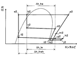
- the inlet / outlet enthalpy difference in the low-stage evaporator 18 is ⁇ h_le as shown in FIG.
- the inlet / outlet enthalpy difference in the low-stage evaporator 18 increases to ⁇ h_le + ⁇ h_iheh.
- the COP improvement effect can be obtained by setting the flow rate ratio Ge / Gn to a small value (that is, making the suction refrigerant flow rate Ge smaller than the injection refrigerant flow rate Gn) and increasing the pressure of the mixed refrigerant in the diffuser portion 19d. Even if it is sufficiently obtained, it is possible to suppress a decrease in the cooling capacity exhibited by the low-stage evaporator 18.
- F1 Can be brought closer.
- ⁇ h_he is an inlet / outlet enthalpy difference in the high-stage evaporator 18.
- the inlet / outlet in the lower-stage evaporator 18 than the comparative cycle in addition to being able to obtain a COP improvement effect by increasing the pressure of the mixed refrigerant in the diffuser portion 19d, the inlet / outlet in the lower-stage evaporator 18 than the comparative cycle.
- the COP improvement effect by enlarging the enthalpy difference can be obtained.
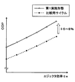
- the COP in the ejector refrigeration cycle 10 of the present embodiment, can be improved by about 6 to 8% compared to the comparative cycle.
- the horizontal axis in FIG. 4 indicates the ejector efficiency, which is the energy conversion efficiency of the ejector, and is a value that varies depending on the operating conditions of the ejector refrigeration cycle 10, the dimensions of the ejector 19, and the like.
- the COP improvement effect by the ejector refrigeration cycle 10 of the present embodiment can be obtained under a wide range of operating conditions of the ejector refrigeration cycle 10, and the ejector refrigeration cycle 10 has a wide range of dimensions. It is also possible to obtain the same ejector 19.
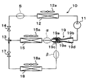
- the internal heat exchanger 16 of this embodiment includes a high-stage low-pressure refrigerant that flows through a refrigerant flow path from the refrigerant outlet side of the high-stage evaporator 15 to the inlet side of the nozzle portion 19a of the ejector 19, and a branching section. 13 performs the function of exchanging heat with the high-pressure refrigerant flowing through the refrigerant flow path from the other refrigerant outlet to the inlet side of the low-stage expansion device 17.
- the refrigerant outlet of the low-stage evaporator 18 and the refrigerant suction port 19c of the ejector 19 are directly connected via the refrigerant pipe.
- Other configurations are the same as those of the first embodiment.
- symbol in the Mollier diagram of FIG. 6 is the same about what shows the state of the refrigerant
- the alphabet is used and the subscripts (numbers) are changed. The same applies to the following Mollier diagram.
- the branching unit 13 branches.
- One refrigerant branched by the branching section 13 is decompressed by the high stage side expansion device 14 and then flows into the high stage side evaporator 15 to absorb heat from the indoor blast air and evaporate (see FIG. 6).
- b6 point ⁇ c6 point ⁇ d6 point Thereby, the indoor blowing air is cooled.
- the high-stage low-pressure refrigerant that has flowed out of the high-stage evaporator 15 flows into the low-pressure side refrigerant passage 16b of the internal heat exchanger 16, and passes through the high-pressure side refrigerant passage 16a of the internal heat exchanger 16.
- the enthalpy is raised by exchanging heat with the other refrigerant branched at the branching portion 13 that circulates (point d6 ⁇ point h6 in FIG. 6).
- the other refrigerant branched at the branching section 13 flows into the high-pressure side refrigerant passage 16a of the internal heat exchanger 16, and flows out of the high-stage evaporator 15 flowing through the low-pressure side refrigerant passage 16b of the internal heat exchanger 16. Heat exchange with the refrigerant reduces the enthalpy (b6 point ⁇ e6 point in FIG. 6).
- the refrigerant that has flowed out of the high-pressure side refrigerant passage 16a of the internal heat exchanger 16 is decompressed by the low-stage side expansion device 17, and then flows into the low-stage side evaporator 18, where it absorbs heat from the blown air for storage and evaporates. (E6 point ⁇ f6 point ⁇ g6 point in FIG. 6). As a result, the internal blown air is cooled.
- the refrigerant that has flowed out of the low-pressure side refrigerant passage 16b of the internal heat exchanger 16 flows into the nozzle portion 19a of the ejector 19 and is isentropically decompressed and injected (point h6 in FIG. 6). ⁇ i6 points).
- coolant g6 point of FIG. 6
- coolant (g6 point of FIG. 6) of the low stage side evaporator 18 is attracted
- the refrigerant injected from the nozzle portion 19a and the suction refrigerant sucked from the refrigerant suction port 19c flow into the diffuser portion 19d of the ejector 19 (i6 ⁇ k6 point, g6 point ⁇ j6 point ⁇ k6 point in FIG. 6). ).
- the velocity energy of the refrigerant is converted into pressure energy, and the pressure of the mixed refrigerant increases (k6 point ⁇ m6 point in FIG. 6). Subsequent operations are the same as those in the first embodiment.
- the vehicle interior and the refrigerator can be cooled at different temperature zones as in the first embodiment, and the internal heat exchanger 16 can be The cooling ability exhibited by the side evaporator 15 and the cooling ability exhibited by the low-stage evaporator 18 can be brought close to each other.
- the enthalpy of the refrigerant flowing into the nozzle portion 19a of the ejector 19 can be raised by the action of the internal heat exchanger 16 by the amount indicated by ⁇ h_ihel in FIG.
- the pressure of the refrigerant can be increased efficiently.
- the ejector 19 collects the loss of velocity energy when the refrigerant is decompressed by the nozzle portion 19a by sucking the refrigerant by the suction action of the injected refrigerant.
- the diffuser portion 19d converts the velocity energy of the mixed refrigerant into pressure energy. Therefore, the amount of pressure increase ⁇ P in the diffuser portion 19d can be increased by increasing the amount of speed energy to be recovered (recovered energy amount).
- the amount of energy recovered by the nozzle portion 19a is the difference between the enthalpy of the enthalpy of the nozzle side 19a inlet side refrigerant (point h6 in FIG. 6) and the enthalpy of the nozzle portion 19a outlet side refrigerant (point i6 in FIG. 6). ( ⁇ H6 in FIG. 6).
- the amount of recovered energy can be increased when the refrigerant is isentropically expanded by a predetermined pressure at the nozzle portion 19a.
- the mixed refrigerant can be efficiently boosted by the diffuser portion 19d.
- the pressure increase ⁇ P in the diffuser portion 19d is increased without increasing the flow rate ratio Ge / Gn, and the mixed refrigerant is boosted in the diffuser portion 19d.
- a sufficient COP improvement effect can be obtained.
- the adjustable range of the flow rate ratio Ge / Gn can be expanded, so that the cooling capacity exhibited by each of the evaporators 15 and 18 is appropriately adjusted. can do.
- the internal heat exchanger 16 of the present embodiment includes a high-stage low-pressure refrigerant that flows through a refrigerant flow path from the refrigerant outlet side of the high-stage evaporator 15 to the inlet side of the nozzle portion 19a of the ejector 19, and a radiator.
- the high-pressure refrigerant flowing through the refrigerant flow path from the refrigerant outlet side of 12 to the inlet side of the branch portion 13 is exchanged.
- the inlet side of the high stage side throttle device 14 is connected to one refrigerant outlet of the branching portion 13, and the inlet side of the low stage side throttle device 17 is connected to the other refrigerant outlet of the branching portion 13. It is connected.
- Other configurations are the same as those of the second embodiment.
- the high-pressure refrigerant flowing out from the radiator 12 flows into the high-pressure side refrigerant passage 16a of the internal heat exchanger 16 and flows through the low-pressure side refrigerant passage 16b of the internal heat exchanger 16.
- the enthalpy is reduced by exchanging heat with the refrigerant flowing out of the vessel 15 (b8 point ⁇ e8 point in FIG. 8).
- the flow of the refrigerant flowing out from the high-pressure side refrigerant passage 16a is branched at the branching section 13.
- One refrigerant branched by the branching section 13 is decompressed by the high stage side expansion device 14 and then flows into the high stage side evaporator 15 and absorbs heat from the indoor blown air, as in the first embodiment. And evaporate (point e8 ⁇ point c8 ⁇ point d8 in FIG. 8). Thereby, the indoor blowing air is cooled.
- the high-stage low-pressure refrigerant that has flowed out of the high-stage evaporator 15 flows into the low-pressure side refrigerant passage 16b of the internal heat exchanger 16, and passes through the high-pressure side refrigerant passage 16a of the internal heat exchanger 16.
- the enthalpy is raised by exchanging heat with the other refrigerant branched at the branching portion 13 that circulates (point d8 ⁇ point h8 in FIG. 8).
- the other refrigerant branched by the branching section 13 is decompressed by the low stage side expansion device 17 and then flows into the low stage side evaporator 18 and absorbs heat from the blown air inside the warehouse to evaporate (FIG. 8). E8 point ⁇ f8 point ⁇ g8 point). As a result, the internal blown air is cooled.
- the refrigerant that has flowed out of the low-pressure side refrigerant passage 16b of the internal heat exchanger 16 flows into the nozzle portion 19a of the ejector 19 and is isentropically decompressed and injected. (Point h8 ⁇ point i8 in FIG. 8). Then, the refrigerant on the downstream side of the low-stage evaporator 18 (g8 point in FIG. 8) is sucked from the refrigerant suction port 19c of the ejector 19 by the suction action of the injection refrigerant. Subsequent operations are the same as those in the second embodiment.
- the vehicle interior and the refrigerator can be cooled at different temperature zones as in the first embodiment. Further, as in the second embodiment, the amount of recovered energy in the nozzle portion 19a (corresponding to ⁇ H8 in FIG. 8) can be increased, and the mixed refrigerant can be efficiently boosted in the diffuser portion 19d.
- the cooling capacity exhibited by the evaporators 15 and 18 can be adjusted appropriately.
- the internal heat exchanger 16 is connected so that the cooling ability exhibited by the high-stage evaporator 15 and the cooling ability exhibited by the low-stage evaporator 18 are close to each other.
- the connection mode of the internal heat exchanger 16 is not limited to this. That is, if the cooling capacity exhibited by each of the evaporators 15 and 18 can be adjusted, the internal heat exchanger 16 can use a low-pressure refrigerant and a high-pressure refrigerant that are different from the combinations disclosed in the above-described embodiments. Heat exchange may be performed.
- the high-pressure refrigerant in the region X high-pressure refrigerant flowing through the refrigerant flow path from the refrigerant outlet side of the radiator 12 to the inlet side of the branching portion 13
- the high-pressure refrigerant in the region Y branching portion 13
- high-pressure refrigerant flowing through the refrigerant flow path from one refrigerant outlet to the inlet side of the high-stage throttle device 14, and high-pressure refrigerant in the region Z from the other refrigerant outlet of the branch portion 13 to the low-stage throttle
- One may be heat exchanged by the internal heat exchanger 16.
- the cooling ability exhibited by the high-stage evaporator 15 is reduced by the low-stage evaporator 18. It can adjust so that it may become larger than the cooling capacity exhibited. Further, heat exchange may be performed between the high-pressure refrigerant in the region X and the low-pressure refrigerant in the region ⁇ .
- the inlet side of the high stage side throttle device 14 is connected to one refrigerant outlet of the branch portion 13, and the inlet of the low stage side throttle device 14 is connected to the other refrigerant outlet of the branch portion 13.
- the ejector refrigeration cycle 10 to which the side is connected has been described, the cycle configuration of the ejector refrigeration cycle of the present disclosure is not limited to this.
- the inlet side of the high stage side throttle device 14 is connected to the refrigerant outlet side of the radiator 12, and the inlet side of the branch portion 13 is connected to the outlet side of the high stage side throttle device 14.
- the refrigerant inlet side of the high-stage evaporator 15 is connected to one refrigerant outlet of the refrigerant 13, and the refrigerant of the low-stage evaporator 18 is connected to the other refrigerant outlet of the branch part 13 via the low-stage throttle device 17.
- a cycle configuration in which the inlet side is connected may be used.
- the internal heat exchanger 16 uses the high-pressure refrigerant in the region S in FIG. 10 (the refrigerant flow path from the refrigerant outlet side of the radiator 12 to the inlet side of the high-stage expansion device 14). What is necessary is just to heat-exchange the high-pressure refrigerant
- the ejector-type refrigeration cycle 10 including the two evaporators 15 and 18 that evaporate the refrigerant in different temperature ranges has been described.
- another evaporator may be provided. This other evaporator may be connected in parallel to the high-stage evaporator 15 or the low-stage evaporator 18, or the high-stage evaporator 15 or the low-stage evaporator 18. May be connected in series.
- the front-seat blown air that is blown to the front seat side of the vehicle by the high-stage evaporator 15 is cooled and blown to the rear-seat side of the vehicle by the low-stage evaporator 18.
- the present invention may be applied to a so-called dual air conditioner system that cools the rear-seat blown air.
- the present invention is not limited to vehicles, and may be applied to stationary refrigeration / freezers, showcases, air conditioners, and the like.
- the low-temperature side cooling target space whose temperature is desired to be lowered is cooled by the low-stage evaporator 18 and cooled in a higher temperature zone than the low-temperature side cooling target space.
- the target space may be cooled by the high-stage evaporator 15.
- Components constituting the ejector refrigeration cycle 10 are not limited to those disclosed in the above-described embodiment.
- an engine-driven compressor driven by a rotational driving force transmitted from an engine (internal combustion engine) via a pulley, a belt, or the like may be employed.
- This type of engine-driven compressor includes a variable displacement compressor that can adjust the refrigerant discharge capacity by changing the discharge capacity, and a fixed type that adjusts the refrigerant discharge capacity by changing the operating rate of the compressor by intermittently connecting the electromagnetic clutch.
- a capacity type compressor or the like can be employed.
- a condensing part that condenses the refrigerant discharged from the compressor 11 by exchanging heat between the refrigerant discharged from the compressor 11 and the outside air, a modulator part that separates the gas-liquid of the refrigerant flowing out from the condensing part, and a modulator part A so-called subcool type condenser configured to have a supercooling unit that supercools the liquid phase refrigerant by exchanging heat between the liquid phase refrigerant flowing out from the outside air and the outside air may be adopted.
- a valve body configured to be able to change the throttle opening degree and an electric actuator composed of a stepping motor that changes the throttle opening degree of the valve body.
- An electric variable aperture mechanism configured as described above may be employed.
- the high-pressure refrigerant and the low-pressure refrigerant can exchange heat by brazing and joining the refrigerant pipe forming the high-pressure side refrigerant passage 16a and the refrigerant pipe forming the low-pressure side refrigerant passage 16b.
- the configuration described above may be adopted.
- the internal heat exchanger 16 may have a configuration in which a plurality of tubes forming the high-pressure side refrigerant passage 16a are provided and the low-pressure side refrigerant passage 16b is formed between adjacent tubes.
- R600a is adopted as the refrigerant
- the refrigerant is not limited to this.
- R134a, R1234yf, R410A, R404A, R32, R1234yfxf, R407C, etc. can be employed.
Abstract
L'invention concerne un cycle de réfrigération d'éjecteur, dans lequel : une entrée d'une partie de buse (19a) d'un éjecteur (19) est reliée à un côté de déchargement de réfrigérant d'un évaporateur d'étage supérieur (15) ; un orifice d'aspiration de réfrigérant (19c) de l'éjecteur (19) est relié au côté de déchargement du réfrigérant d'un évaporateur d'étage inférieur (18) ; et un échangeur thermique interne (16) est fourni dans lequel un réfrigérant haute pression s'écoulant vers un dispositif d'étranglement d'étage inférieur (17) pour abaisser la pression du réfrigérant s'écoulant vers l'évaporateur d'étage inférieur (18), échange la chaleur avec le réfrigérant basse pression d'étage inférieur s'écoulant hors de l'évaporateur d'étage inférieur (18). Ainsi, étant donné qu'il est possible d'augmenter la différence d'enthalpie sortie/entrée dans l'évaporateur d'étage inférieur (18), il est possible de rapprocher l'une de l'autre les capacités de refroidissement démontrées par les évaporateurs (15, 18) même si le rapport d'écoulement (Ge/Gn) entre le débit d'écoulement (Ge) du réfrigérant d'admission et le débit d'écoulement (Gn) du réfrigérant d'injection est réglé sur une valeur comparativement petite afin d'améliorer le coefficient de performance (COP) pour le cycle.
Priority Applications (3)
| Application Number | Priority Date | Filing Date | Title |
|---|---|---|---|
| DE112015002568.5T DE112015002568T5 (de) | 2014-05-30 | 2015-05-18 | Ejektor-Kühlkreislauf |
| US15/304,667 US10132526B2 (en) | 2014-05-30 | 2015-05-18 | Ejector refrigeration cycle |
| CN201580021596.6A CN106233082B (zh) | 2014-05-30 | 2015-05-18 | 喷射器式制冷循环 |
Applications Claiming Priority (2)
| Application Number | Priority Date | Filing Date | Title |
|---|---|---|---|
| JP2014112156A JP6277869B2 (ja) | 2014-05-30 | 2014-05-30 | エジェクタ式冷凍サイクル |
| JP2014-112156 | 2014-05-30 |
Publications (1)
| Publication Number | Publication Date |
|---|---|
| WO2015182057A1 true WO2015182057A1 (fr) | 2015-12-03 |
Family
ID=54698414
Family Applications (1)
| Application Number | Title | Priority Date | Filing Date |
|---|---|---|---|
| PCT/JP2015/002488 WO2015182057A1 (fr) | 2014-05-30 | 2015-05-18 | Cycle de réfrigération d'éjecteur |
Country Status (5)
| Country | Link |
|---|---|
| US (1) | US10132526B2 (fr) |
| JP (1) | JP6277869B2 (fr) |
| CN (1) | CN106233082B (fr) |
| DE (1) | DE112015002568T5 (fr) |
| WO (1) | WO2015182057A1 (fr) |
Families Citing this family (13)
| Publication number | Priority date | Publication date | Assignee | Title |
|---|---|---|---|---|
| US10254015B2 (en) * | 2017-02-28 | 2019-04-09 | Thermo King Corporation | Multi-zone transport refrigeration system with an ejector system |
| JP2019074300A (ja) * | 2017-04-17 | 2019-05-16 | 三星電子株式会社Samsung Electronics Co.,Ltd. | 冷凍サイクル装置、その制御方法、及び三方流量制御弁 |
| KR102496363B1 (ko) * | 2017-04-17 | 2023-02-06 | 삼성전자주식회사 | 냉장고 |
| WO2018194324A1 (fr) | 2017-04-17 | 2018-10-25 | Samsung Electronics Co., Ltd. | Dispositif à cycle de réfrigération et soupape de régulation de débit à trois voies |
| JP6708161B2 (ja) * | 2017-04-24 | 2020-06-10 | 株式会社デンソー | エジェクタ式冷凍サイクル |
| CN106969531A (zh) * | 2017-05-09 | 2017-07-21 | 上海海洋大学 | 一种双蒸发温度喷射式制冷系统 |
| JP2019056536A (ja) * | 2017-09-22 | 2019-04-11 | パナソニックIpマネジメント株式会社 | 冷凍サイクル装置 |
| CN107990580B (zh) * | 2017-11-07 | 2019-05-10 | 西安交通大学 | 一种多次分离喷射增效的自复叠热泵系统及运行模式 |
| JP7077733B2 (ja) * | 2018-04-06 | 2022-05-31 | 株式会社デンソー | エジェクタ式冷凍サイクル |
| JP6939691B2 (ja) * | 2018-04-27 | 2021-09-22 | 株式会社デンソー | エジェクタ式冷凍サイクル |
| US11148814B2 (en) * | 2019-10-03 | 2021-10-19 | Hamilton Sundstrand Corporation | Refrigeration circuits, environmental control systems, and methods of controlling flow in refrigeration circuits |
| GB2589841A (en) * | 2019-11-15 | 2021-06-16 | The Univ Of Hull | A heat pump system |
| DE102021000482A1 (de) | 2021-02-01 | 2022-08-04 | Mercedes-Benz Group AG | Temperiervorrichtung für ein Fahrzeug |
Citations (3)
| Publication number | Priority date | Publication date | Assignee | Title |
|---|---|---|---|---|
| JP2008082693A (ja) * | 2006-08-28 | 2008-04-10 | Calsonic Kansei Corp | 冷凍サイクル |
| JP2012149790A (ja) * | 2011-01-17 | 2012-08-09 | Mitsubishi Electric Corp | 冷凍サイクル装置及び流路切替装置及び流路切替方法 |
| JP2013200057A (ja) * | 2012-03-23 | 2013-10-03 | Sanden Corp | 冷凍サイクル及び冷凍ショーケース |
Family Cites Families (7)
| Publication number | Priority date | Publication date | Assignee | Title |
|---|---|---|---|---|
| JP4595607B2 (ja) * | 2005-03-18 | 2010-12-08 | 株式会社デンソー | エジェクタを使用した冷凍サイクル |
| CN100545546C (zh) | 2005-04-01 | 2009-09-30 | 株式会社电装 | 喷射器型制冷循环 |
| JP4626531B2 (ja) | 2005-04-01 | 2011-02-09 | 株式会社デンソー | エジェクタ式冷凍サイクル |
| JP2007192502A (ja) * | 2006-01-20 | 2007-08-02 | Denso Corp | 熱交換器 |
| JP4572910B2 (ja) * | 2007-06-11 | 2010-11-04 | 株式会社デンソー | 二段減圧式エジェクタおよびエジェクタ式冷凍サイクル |
| CN103148629B (zh) * | 2013-02-28 | 2014-12-24 | 西安交通大学 | 用于双温直冷式电冰箱的气液两相流喷射器增效制冷系统 |
| JP5962596B2 (ja) | 2013-06-18 | 2016-08-03 | 株式会社デンソー | エジェクタ式冷凍サイクル |
-
2014
- 2014-05-30 JP JP2014112156A patent/JP6277869B2/ja not_active Expired - Fee Related
-
2015
- 2015-05-18 WO PCT/JP2015/002488 patent/WO2015182057A1/fr active Application Filing
- 2015-05-18 CN CN201580021596.6A patent/CN106233082B/zh active Active
- 2015-05-18 DE DE112015002568.5T patent/DE112015002568T5/de active Pending
- 2015-05-18 US US15/304,667 patent/US10132526B2/en active Active
Patent Citations (3)
| Publication number | Priority date | Publication date | Assignee | Title |
|---|---|---|---|---|
| JP2008082693A (ja) * | 2006-08-28 | 2008-04-10 | Calsonic Kansei Corp | 冷凍サイクル |
| JP2012149790A (ja) * | 2011-01-17 | 2012-08-09 | Mitsubishi Electric Corp | 冷凍サイクル装置及び流路切替装置及び流路切替方法 |
| JP2013200057A (ja) * | 2012-03-23 | 2013-10-03 | Sanden Corp | 冷凍サイクル及び冷凍ショーケース |
Also Published As
| Publication number | Publication date |
|---|---|
| JP2015224861A (ja) | 2015-12-14 |
| DE112015002568T5 (de) | 2017-02-23 |
| JP6277869B2 (ja) | 2018-02-14 |
| US20170045269A1 (en) | 2017-02-16 |
| CN106233082A (zh) | 2016-12-14 |
| US10132526B2 (en) | 2018-11-20 |
| CN106233082B (zh) | 2019-08-02 |
Similar Documents
| Publication | Publication Date | Title |
|---|---|---|
| JP6277869B2 (ja) | エジェクタ式冷凍サイクル | |
| CN109312962B (zh) | 制冷循环装置 | |
| JP5195364B2 (ja) | エジェクタ式冷凍サイクル | |
| JP5413393B2 (ja) | 冷媒分配器および冷凍サイクル | |
| US7823401B2 (en) | Refrigerant cycle device | |
| JP6350108B2 (ja) | エジェクタ、およびエジェクタ式冷凍サイクル | |
| JP5018724B2 (ja) | エジェクタ式冷凍サイクル | |
| JP5359231B2 (ja) | エジェクタ式冷凍サイクル | |
| WO2018198609A1 (fr) | Cycle de réfrigération a éjecteur | |
| CN110382880B (zh) | 喷射器组件 | |
| WO2019017168A1 (fr) | Cycle frigorifique de type-éjecteur | |
| JP6717234B2 (ja) | エジェクタモジュール | |
| WO2019208428A1 (fr) | Cycle de réfrigération de type-éjecteur | |
| JP2018119542A (ja) | エジェクタ | |
| WO2017217142A1 (fr) | Dispositif à cycle de réfrigération | |
| JP6547698B2 (ja) | エジェクタ式冷凍サイクル | |
| JP5991271B2 (ja) | エジェクタ式冷凍サイクル | |
| JP2022088798A (ja) | 冷凍サイクル装置 | |
| WO2018159321A1 (fr) | Module éjecteur | |
| JP6327088B2 (ja) | エジェクタ式冷凍サイクル | |
| JP2019190795A (ja) | エジェクタ式冷凍サイクル | |
| JP2008304078A (ja) | 冷凍サイクル装置 | |
| WO2019155806A1 (fr) | Cycle frigorifique de type éjecteur, et module d'éjecteur | |
| WO2018139417A1 (fr) | Éjecteur | |
| JP2019138617A (ja) | エジェクタ式冷凍サイクル、およびエジェクタモジュール |
Legal Events
| Date | Code | Title | Description |
|---|---|---|---|
| 121 | Ep: the epo has been informed by wipo that ep was designated in this application |
Ref document number: 15799625 Country of ref document: EP Kind code of ref document: A1 |
|
| WWE | Wipo information: entry into national phase |
Ref document number: 15304667 Country of ref document: US |
|
| WWE | Wipo information: entry into national phase |
Ref document number: 112015002568 Country of ref document: DE |
|
| 122 | Ep: pct application non-entry in european phase |
Ref document number: 15799625 Country of ref document: EP Kind code of ref document: A1 |