WO2015182057A1 - Ejector refrigeration cycle - Google Patents
Ejector refrigeration cycle Download PDFInfo
- Publication number
- WO2015182057A1 WO2015182057A1 PCT/JP2015/002488 JP2015002488W WO2015182057A1 WO 2015182057 A1 WO2015182057 A1 WO 2015182057A1 JP 2015002488 W JP2015002488 W JP 2015002488W WO 2015182057 A1 WO2015182057 A1 WO 2015182057A1
- Authority
- WO
- WIPO (PCT)
- Prior art keywords
- refrigerant
- pressure
- evaporator
- stage
- ejector
- Prior art date
Links
Images


Classifications
-
- F—MECHANICAL ENGINEERING; LIGHTING; HEATING; WEAPONS; BLASTING
- F25—REFRIGERATION OR COOLING; COMBINED HEATING AND REFRIGERATION SYSTEMS; HEAT PUMP SYSTEMS; MANUFACTURE OR STORAGE OF ICE; LIQUEFACTION SOLIDIFICATION OF GASES
- F25B—REFRIGERATION MACHINES, PLANTS OR SYSTEMS; COMBINED HEATING AND REFRIGERATION SYSTEMS; HEAT PUMP SYSTEMS
- F25B5/00—Compression machines, plants or systems, with several evaporator circuits, e.g. for varying refrigerating capacity
- F25B5/02—Compression machines, plants or systems, with several evaporator circuits, e.g. for varying refrigerating capacity arranged in parallel
-
- F—MECHANICAL ENGINEERING; LIGHTING; HEATING; WEAPONS; BLASTING
- F25—REFRIGERATION OR COOLING; COMBINED HEATING AND REFRIGERATION SYSTEMS; HEAT PUMP SYSTEMS; MANUFACTURE OR STORAGE OF ICE; LIQUEFACTION SOLIDIFICATION OF GASES
- F25B—REFRIGERATION MACHINES, PLANTS OR SYSTEMS; COMBINED HEATING AND REFRIGERATION SYSTEMS; HEAT PUMP SYSTEMS
- F25B1/00—Compression machines, plants or systems with non-reversible cycle
- F25B1/06—Compression machines, plants or systems with non-reversible cycle with compressor of jet type, e.g. using liquid under pressure
-
- F—MECHANICAL ENGINEERING; LIGHTING; HEATING; WEAPONS; BLASTING
- F25—REFRIGERATION OR COOLING; COMBINED HEATING AND REFRIGERATION SYSTEMS; HEAT PUMP SYSTEMS; MANUFACTURE OR STORAGE OF ICE; LIQUEFACTION SOLIDIFICATION OF GASES
- F25B—REFRIGERATION MACHINES, PLANTS OR SYSTEMS; COMBINED HEATING AND REFRIGERATION SYSTEMS; HEAT PUMP SYSTEMS
- F25B40/00—Subcoolers, desuperheaters or superheaters
-
- F—MECHANICAL ENGINEERING; LIGHTING; HEATING; WEAPONS; BLASTING
- F25—REFRIGERATION OR COOLING; COMBINED HEATING AND REFRIGERATION SYSTEMS; HEAT PUMP SYSTEMS; MANUFACTURE OR STORAGE OF ICE; LIQUEFACTION SOLIDIFICATION OF GASES
- F25B—REFRIGERATION MACHINES, PLANTS OR SYSTEMS; COMBINED HEATING AND REFRIGERATION SYSTEMS; HEAT PUMP SYSTEMS
- F25B41/00—Fluid-circulation arrangements
-
- F—MECHANICAL ENGINEERING; LIGHTING; HEATING; WEAPONS; BLASTING
- F25—REFRIGERATION OR COOLING; COMBINED HEATING AND REFRIGERATION SYSTEMS; HEAT PUMP SYSTEMS; MANUFACTURE OR STORAGE OF ICE; LIQUEFACTION SOLIDIFICATION OF GASES
- F25B—REFRIGERATION MACHINES, PLANTS OR SYSTEMS; COMBINED HEATING AND REFRIGERATION SYSTEMS; HEAT PUMP SYSTEMS
- F25B2341/00—Details of ejectors not being used as compression device; Details of flow restrictors or expansion valves
- F25B2341/001—Ejectors not being used as compression device
- F25B2341/0011—Ejectors with the cooled primary flow at reduced or low pressure
Definitions
- the present disclosure relates to an ejector-type refrigeration cycle including a plurality of evaporators that evaporate a refrigerant in different temperature zones.
- an ejector-type refrigeration cycle which is a vapor compression refrigeration cycle apparatus including an ejector, is known.
- the refrigerant that has flowed out of the evaporator due to the suction action of the high-speed jet refrigerant injected from the nozzle portion of the ejector is sucked from the refrigerant suction port of the ejector, and the diffuser portion (pressure booster) of the ejector
- the pressure of the mixed refrigerant of the injection refrigerant and the suction refrigerant is increased in step, and the mixed refrigerant whose pressure is increased in the diffuser section is sucked into the compressor.
- the power consumption of the compressor is reduced and the coefficient of performance (COP) of the cycle is reduced compared to a normal refrigeration cycle apparatus in which the refrigerant evaporation pressure in the evaporator and the suction refrigerant pressure in the compressor are substantially equal. ) Can be improved.
- Patent Document 1 includes two evaporators as this type of ejector-type refrigeration cycle, and the refrigerant flowing out from one evaporator (first evaporator) flows into the nozzle portion of the ejector and the other is evaporated.
- first evaporator the refrigerant flowing out from one evaporator
- coolant which flowed out from the container (2nd evaporator) from the refrigerant
- the refrigerant evaporation temperature in the first evaporator and the refrigerant evaporation temperature in the second evaporator are in different temperature zones. Therefore, in Patent Document 1, this ejector refrigeration cycle is applied to a cold insulation device, and the first evaporator and the second evaporator are arranged in different cold insulation chambers (cooling target spaces), and the respective cold insulation chambers are different. The temperature can be kept cool.
- required of each evaporator is different.
- the cooling capacity is defined by the integrated value of the enthalpy difference obtained by subtracting the enthalpy of the refrigerant on the inlet side of the evaporator from the enthalpy of the refrigerant on the outlet side of the evaporator and the refrigerant flow rate (mass flow rate) flowing through the evaporator.
- the refrigerant is sucked by the sucking action of the jetted refrigerant, thereby recovering the speed energy loss when the refrigerant is decompressed at the nozzle portion. Then, the mixed refrigerant is pressurized by converting the velocity energy of the mixed refrigerant of the injected refrigerant and the suction refrigerant into pressure energy in the diffuser section.
- the flow rate ratio Ge / Gn is reduced, so that the flow rate of the refrigerant flowing through the second evaporator decreases, so that the cooling capacity exhibited by the second evaporator is the cooling capacity exhibited by the first evaporator. It will be lower than.
- the flow ratio Ge / Gn is increased, the cooling capacity exhibited by the second evaporator can be brought closer to the cooling capacity exhibited by the first evaporator, but the pressure increase amount ⁇ P decreases. Therefore, it becomes difficult to obtain the COP improvement effect.
- the present disclosure provides a first feature that in a ejector refrigeration cycle including a plurality of evaporators that evaporate a refrigerant in different temperature zones, the cooling capacity exhibited by each evaporator can be adjusted. Objective.
- a second object of the present disclosure is to bring the cooling capacity exhibited by each evaporator closer in an ejector refrigeration cycle including a plurality of evaporators that evaporate a refrigerant in different temperature zones.
- An ejector-type refrigeration cycle includes a compressor that compresses and discharges a refrigerant, a radiator that dissipates heat from the refrigerant discharged from the compressor, and a first that depressurizes refrigerant that flows out of the radiator.
- a decompressor and a second decompressor a first evaporator that evaporates the refrigerant decompressed by the first decompressor, a second evaporator that evaporates the refrigerant decompressed by the second decompressor, and the first evaporation Refrigerant sucked from the refrigerant suction port by the suction action of the high-speed jet refrigerant jetted from the nozzle part that decompresses the refrigerant flowing out of the evaporator, and sucked from the jet refrigerant and the refrigerant suction port And an ejector for mixing and boosting.
- the ejector-type refrigeration cycle includes (i) a refrigerant flow path from the refrigerant outlet side of the radiator to the inlet side of the first decompressor, and a refrigerant flow from the refrigerant outlet side of the radiator to the inlet side of the second decompressor.
- the refrigerant flowing through at least one of the refrigerant flow paths is a high-pressure refrigerant
- the refrigerant flowing through the refrigerant flow path from the refrigerant outlet side of the first evaporator to the inlet side of the nozzle portion is the high-stage low pressure
- the refrigerant flowing through the refrigerant flow path from the refrigerant outlet side of the second evaporator to the refrigerant suction port is a low-stage low-pressure refrigerant
- the high-stage low-pressure refrigerant and the low-stage low-pressure refrigerant An internal heat exchanger for exchanging heat between any one of them and the high-pressure refrigerant is provided.
- the refrigerant evaporation temperature in the second evaporator is set. It can be set as the temperature range lower than the refrigerant
- the ejector refrigeration cycle includes an internal heat exchanger that exchanges heat between either the high-stage low-pressure refrigerant or the low-stage low-pressure refrigerant and the high-pressure refrigerant.
- an enthalpy difference obtained by subtracting the enthalpy of the inlet side refrigerant of each evaporator from the enthalpy of the outlet side refrigerant of each evaporator (hereinafter simply referred to as an inlet / outlet enthalpy difference in each evaporator), or a nozzle. It is possible to increase the enthalpy of the refrigerant flowing into the section, and the cooling capacity exhibited by each evaporator can be adjusted.
- an ejector-type refrigeration cycle includes a branch part that branches the flow of refrigerant that has flowed out of a radiator, and the inlet side of the first decompression device is connected to one refrigerant outlet of the branch part.
- the other refrigerant outlet is connected to the inlet side of the second decompression device, and the internal heat exchanger includes a low-stage low-pressure refrigerant and the other refrigerant outlet of the branch portion to the inlet side of the second decompression device. Heat exchange may be performed with the high-pressure refrigerant flowing through the refrigerant flow path.
- the internal heat exchanger can cool the high-pressure refrigerant flowing through the refrigerant flow path from the other refrigerant outlet of the branch portion to the inlet side of the second decompression device, the second evaporator The entrance and exit enthalpy difference at can be expanded.
- the ejector refrigeration cycle includes a branch portion that branches the flow of the refrigerant that has flowed out of the radiator, and the inlet side of the first decompression device is connected to one refrigerant outlet of the branch portion.
- the other refrigerant outlet is connected to the inlet side of the second decompression device, and the internal heat exchanger has a high-stage low-pressure refrigerant and the other refrigerant outlet of the branch portion to the inlet side of the second decompression device. Heat exchange may be performed with the high-pressure refrigerant flowing through the refrigerant flow path.
- the cooling capacity exhibited by the first evaporator and the cooling capacity exhibited by the second evaporator can be brought close to each other. Furthermore, the enthalpy of the refrigerant flowing into the nozzle portion of the ejector can be increased by heating the high-stage low-pressure refrigerant in the internal heat exchanger.
- the amount of energy recovered by the ejector can be increased, and the boost amount ⁇ P of the ejector can be increased without reducing the flow rate ratio Ge / Gn.
- the cooling ability exhibited by the first evaporator and the cooling ability exhibited by the second evaporator can be brought close to each other.
- the ejector refrigeration cycle includes a branch portion that branches the flow of the refrigerant that has flowed out of the radiator, and the inlet side of the first decompression device is connected to one refrigerant outlet of the branch portion.
- the other refrigerant outlet is connected to the inlet side of the second decompression device, and the internal heat exchanger includes a high-stage low-pressure refrigerant and a refrigerant flow path from the refrigerant outlet side of the radiator to the inlet side of the branch portion. It is possible to exchange heat with a high-pressure refrigerant that circulates.
- the cooling capacity exhibited by the first evaporator and the cooling capacity exhibited by the second evaporator are brought close to each other. Can do.
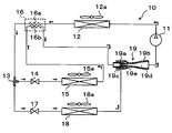
- the ejector refrigeration cycle 10 is applied to a vehicle refrigeration cycle apparatus mounted on a refrigerated vehicle.
- This refrigeration cycle device for a vehicle has a function of cooling indoor air blown into a vehicle compartment in a refrigerated vehicle, and a function of cooling internal blown air sent into a refrigerator arranged in a loading platform of the vehicle Is responsible.
- both the vehicle interior space and the refrigerator internal space are cooling target spaces of the ejector refrigeration cycle 10. Furthermore, in this embodiment, the volume in a vehicle interior and a refrigerator is substantially equivalent, and the cooling capacity required in order to cool each cooling object space is also equivalent.
- the cooling capacity in this embodiment is obtained by subtracting the enthalpy of the outlet side refrigerant of the evaporator provided in the ejector-type refrigeration cycle 10 from the enthalpy of the inlet side refrigerant of the evaporator (entrance / entrance difference). It is defined by an integrated value with the flow rate of refrigerant flowing (mass flow rate).
- the compressor 11 sucks in refrigerant, compresses it, and discharges it.
- the compressor 11 of the present embodiment is an electric compressor configured by housing a fixed capacity type compression mechanism and an electric motor that drives the compression mechanism in one housing.
- compression mechanism various compression mechanisms such as a scroll-type compression mechanism and a vane-type compression mechanism can be adopted. Further, the operation (rotation speed) of the electric motor is controlled by a control signal output from a control device to be described later, and any type of an AC motor and a DC motor may be used.
- a natural refrigerant (specifically, R600a) is adopted as the refrigerant, and the vapor compression subcriticality in which the high-pressure side refrigerant pressure does not exceed the refrigerant critical pressure. It constitutes the refrigeration cycle. Furthermore, refrigeration oil for lubricating the compressor 11 is mixed in the refrigerant, and a part of the refrigeration oil circulates in the cycle together with the refrigerant.
- the refrigerant inlet side of the radiator 12 is connected to the discharge port of the compressor 11.
- the radiator 12 is a heat exchanger for radiating heat by exchanging heat between the refrigerant discharged from the compressor 11 and outside air (outside air) blown by the cooling fan 12a to radiate the high-pressure refrigerant.
- the cooling fan 12a is an electric blower in which the number of rotations (the amount of blown air) is controlled by a control voltage output from the control device.
- the refrigerant outlet side of the radiator 12 is connected to the refrigerant inlet of the branching portion 13 that branches the flow of the refrigerant flowing out of the radiator 12.
- the branch portion 13 is configured by a three-way joint having three inflow / outflow ports, and one of the three inflow / outflow ports is a refrigerant inflow port, and the remaining two are refrigerant outflow ports.
- Such a three-way joint may be formed by joining pipes having different pipe diameters, or may be formed by providing a plurality of refrigerant passages in a metal block or a resin block.
- the inlet side of a high-stage expansion device 14 as a first decompression device is connected to one refrigerant outlet of the branch part 13.
- the high stage side expansion device 14 includes a temperature sensing unit that detects the degree of superheat of the high stage side evaporator 15 outlet side refrigerant based on the temperature and pressure of the high stage side evaporator 15 outlet side refrigerant, This is a temperature type expansion valve that adjusts the throttle passage area by a mechanical mechanism so that the degree of superheat of the refrigerant on the outlet side of the container 15 is within a predetermined reference range.
- the refrigerant inlet side of the high stage evaporator 15 as the first evaporator is connected to the outlet side of the high stage side expansion device 14.
- the high-stage evaporator 15 evaporates the low-pressure refrigerant by exchanging heat between the low-pressure refrigerant decompressed by the high-stage side expansion device 14 and the indoor blown air blown into the vehicle interior from the high-stage blower fan 15a. This is an endothermic heat exchanger that exerts an endothermic effect.
- the high stage side blower fan 15a is an electric blower in which the rotation speed (the amount of blown air) is controlled by a control voltage output from the control device.
- An inlet side of a nozzle portion 19 a of an ejector 19 described later is connected to the refrigerant outlet side of the high stage evaporator 15.
- the other refrigerant outlet of the branch part 13 is connected to the inlet side of the high-pressure side refrigerant passage 16a of the internal heat exchanger 16.
- the internal heat exchanger 16 of the present embodiment has a function of exchanging heat between the high-pressure refrigerant that has flowed out from the other refrigerant outlet of the branch portion 13 and the low-stage low-pressure refrigerant that has flowed out from the low-stage evaporator 18 described later. Fulfill.
- the inlet side of the low-stage expansion device 17 as the second decompression device is connected to the outlet side of the high-pressure side refrigerant passage 16a of the internal heat exchanger 16.
- the low-stage side throttle device 17 is a fixed throttle with a fixed throttle opening, and specifically, a nozzle, an orifice, a capillary tube, or the like can be adopted.
- the refrigerant inlet side of the low stage evaporator 18 as the second evaporator is connected to the outlet side of the low stage expansion device 17.
- the low-stage evaporator 18 exchanges heat between the low-pressure refrigerant decompressed by the low-stage side expansion device 17 and the internal blown air circulated into the refrigerator from the low-stage blower fan 18a.
- An endothermic heat exchanger that evaporates the refrigerant and exerts an endothermic effect.
- the basic configuration of the low-stage evaporator 18 is the same as that of the high-stage evaporator 15, and the basic configuration of the low-stage fan 18a is the same as that of the high-stage fan 15a.
- An inlet side of the low-pressure side refrigerant passage 16 b of the internal heat exchanger 16 is connected to the refrigerant outlet side of the low-stage evaporator 18.
- a refrigerant suction port 19c side of an ejector 19 described later is connected to the outlet side of the low-pressure side refrigerant passage 16b.
- the throttle opening degree of the low stage side throttle device 17 of the present embodiment is set to be smaller than the throttle opening degree of the high stage side throttle device 14 during the normal operation of the cycle. Therefore, the refrigerant evaporation pressure (refrigerant evaporation temperature) in the low stage side evaporator 18 is lower than the refrigerant evaporation pressure (refrigerant evaporation temperature) in the high stage side evaporator 15.
- the high stage side throttle device 14 during normal operation of the cycle is set so that the flow rate ratio Ge / Gn of the suction refrigerant flow rate Ge to the injection refrigerant flow rate Gn is within a predetermined reference range of 1 or less.
- the throttle opening degree (flow rate characteristic), the throttle opening degree (flow rate characteristic) of the low stage side throttle device 17, the passage cross-sectional area of each refrigerant passage of the branch portion 13, and the like are determined.
- the injected refrigerant flow rate Gn is a refrigerant flow rate (mass flow rate) flowing into the nozzle portion 19a of the ejector 19 via the high stage side expansion device 14 and the high stage side evaporator 18.
- the suction refrigerant flow rate Ge is a refrigerant flow rate sucked from the refrigerant suction port 19c of the ejector 19 through the high-pressure side refrigerant passage 16a, the low-stage side expansion device 17 and the low-stage side evaporator 18 of the internal heat exchanger 16. (Mass flow rate).
- the injection refrigerant flow rate Gn is the refrigerant flow rate flowing through the high-stage evaporator 15
- the suction refrigerant flow rate Ge is the refrigerant flow rate flowing through the low-stage evaporator 18.
- the ejector 19 functions as a decompression device that depressurizes the refrigerant that has flowed out of the high-stage evaporator 15, and also flows out of the low-stage evaporator 18 by the suction action of the injected refrigerant that is injected at high speed. It functions as a refrigerant circulation section (refrigerant transport section) that sucks (transports) the refrigerant and circulates it in the cycle.
- refrigerant circulation section refrigerant transport section
- the nozzle portion 19a is formed of a substantially cylindrical metal (for example, stainless steel alloy) or the like that gradually tapers in the refrigerant flow direction, and the like in the refrigerant passage (throttle passage) formed inside. It expands under reduced pressure entropy.
- a throat portion (minimum passage area portion) having the smallest passage cross-sectional area is formed, and further, the refrigerant flows from the throat portion toward the refrigerant injection port for injecting the refrigerant.
- a divergent part in which the passage area gradually increases is formed. That is, the nozzle part 19a is configured as a Laval nozzle.
- the nozzle portion 19a is set such that the flow rate of the injected refrigerant injected from the refrigerant injection port is equal to or higher than the sonic speed during normal operation of the ejector refrigeration cycle 10.
- the body portion 19b is formed of a substantially cylindrical metal (for example, aluminum), functions as a fixing member that supports and fixes the nozzle portion 19a therein, and forms an outer shell of the ejector 19. More specifically, the nozzle portion 19a is fixed by press-fitting so as to be housed inside the longitudinal end of the body portion 19b. Therefore, the refrigerant does not leak from the fixed portion (press-fit portion) between the nozzle portion 19a and the body portion 19b.
- a substantially cylindrical metal for example, aluminum
- a refrigerant suction port 19c provided so as to penetrate the inside and outside of the outer peripheral surface of the body portion 19b and communicate with the refrigerant injection port of the nozzle portion 19a is provided in a portion corresponding to the outer peripheral side of the nozzle portion 19a. Is formed.
- the refrigerant suction port 19 c is a through hole that sucks the refrigerant that has flowed out of the low-stage evaporator 18 into the ejector 19 by the suction action of the jet refrigerant that is ejected from the nozzle portion 19 a.
- a suction passage 19e that guides the suction refrigerant sucked from the refrigerant suction port 19c to the refrigerant injection port side of the nozzle portion 19a, and an ejector 19 from the refrigerant suction port 19c through the suction passage 19e.
- a diffuser portion 19d is formed as a boosting portion that mixes and sucks the suction refrigerant and the injection refrigerant that flow into the interior.
- the suction passage 19e is formed in a space between the outer peripheral side around the tapered tip of the nozzle portion 19a and the inner peripheral side of the body portion 19b, and the refrigerant passage area of the suction passage 19e is in the refrigerant flow direction. It is gradually shrinking. Thereby, the flow rate of the suction refrigerant flowing through the suction passage 19e is gradually increased, and the energy loss (mixing loss) when the suction refrigerant and the injection refrigerant are mixed in the diffuser portion 19d is reduced.
- the diffuser portion 19d is disposed so as to be continuous with the outlet of the suction passage 19e, and is formed so that the refrigerant passage area gradually increases.
- the cross-sectional shape of the inner peripheral wall surface of the body portion 19b that forms the diffuser portion 19d of the present embodiment is formed by combining a plurality of curves. And since the degree of spread of the refrigerant passage cross-sectional area of the diffuser portion 19d gradually increases in the refrigerant flow direction and then decreases again, the refrigerant can be increased in an isentropic manner.
- a suction port of the compressor 11 is connected to the outlet side of the diffuser portion 19 d of the ejector 19.
- the compressor 11, the radiator 12, the cooling fan 12a, and the like are housed in one housing and integrally configured as an outdoor unit. Furthermore, the outdoor unit is arranged on the vehicle front side above the refrigerator.
- a control device (not shown) is composed of a well-known microcomputer including a CPU, ROM, RAM, etc. and its peripheral circuits, performs various calculations and processing based on a control program stored in the ROM, and is connected to the output side.
- the operation of various control target devices (the compressor 11, the cooling fan 12a, the high-stage side fan 15a, the low-stage side fan 18a, etc.) is controlled.
- control device includes an inside air temperature sensor that detects the interior temperature of the vehicle, an outside air temperature sensor that detects the outside air temperature, a solar radiation sensor that detects the amount of solar radiation in the interior of the vehicle, and the air temperature of the high-stage evaporator 15
- the first evaporator temperature sensor for detecting the side evaporator temperature
- the second evaporator temperature sensor for detecting the blown air temperature (low stage evaporator temperature) of the low stage evaporator 18, and the refrigerant on the outlet side refrigerant of the radiator 12
- Sensor groups such as an outlet side temperature sensor for detecting temperature, an outlet side pressure sensor for detecting the pressure of the refrigerant on the outlet side of the radiator 12, and an in-chamber temperature sensor for detecting the temperature in the refrigerator are connected, and detection of these sensor groups is performed. A value is entered.
- an operation panel (not shown) disposed near the instrument panel in the front part of the vehicle interior is connected to the input side of the control device, and operation signals from various operation switches provided on the operation panel are input to the control device.
- various operation switches provided on the operation panel there are provided an operation switch for requesting operation or stop of the vehicle refrigeration cycle apparatus, a vehicle interior temperature setting switch for setting the vehicle interior temperature, and the like.
- control device of the present embodiment is configured integrally with a control unit that controls the operation of various control target devices connected to the output side of the control device.
- a configuration (hardware and software) for controlling the operation constitutes a control unit of each control target device.
- operation of the compressor 11 comprises the discharge capability control part.
- the control device operates the electric motor of the compressor 11, the cooling fan 12a, the high stage side fan 15a, the low stage side fan 18a, and the like. Thereby, the compressor 11 sucks the refrigerant, compresses it, and discharges it.
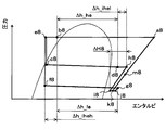
- One refrigerant branched in the branching section 13 flows into the high stage side expansion device 14 and is decompressed in an enthalpy manner (b2 point ⁇ c2 point in FIG. 2).
- the opening degree of the high stage side expansion device 14 is adjusted so that the degree of superheat of the high stage side evaporator 15 outlet side refrigerant (point d2 in FIG. 2) is within a predetermined range.
- the refrigerant decompressed by the high stage side expansion device 14 flows into the high stage side evaporator 15, absorbs heat from the indoor blown air blown by the high stage side blower fan 15a, and evaporates (c2 in FIG. 2). Point ⁇ d2 point). Thereby, the indoor blowing air is cooled.
- the other refrigerant branched at the branch portion 13 flows into the high-pressure side refrigerant passage 16a of the internal heat exchanger 16, and flows out of the low-stage evaporator 18 flowing through the low-pressure side refrigerant passage 16b of the internal heat exchanger 16.
- enthalpy (b2 point ⁇ e2 point in FIG. 2).
- the refrigerant that has flowed out of the high-pressure side refrigerant passage 16a of the internal heat exchanger 16 flows into the low-stage expansion device 17 and is decompressed in an enthalpy manner (point e2 ⁇ point f2 in FIG. 2).
- the pressure of the refrigerant depressurized by the low stage side expansion device 17 is lower than the pressure of the refrigerant depressurized by the high stage side expansion device 14.
- the pressure at point e2 is lower than the pressure at point c2.
- the refrigerant depressurized by the low-stage expansion device 17 flows into the low-stage evaporator 18 and absorbs heat from the internal blown air circulated by the low-stage blower fan 18a to evaporate (FIG. 2). F2 point ⁇ g2 point). As a result, the internal blown air is cooled.
- the enthalpy is raised by exchanging heat with the other refrigerant branched in this way (point g2 ⁇ point h2 in FIG. 2).
- the refrigerant that has flowed out of the high-stage evaporator 15 flows into the nozzle portion 19a of the ejector 19 and is isentropically decompressed and injected (point d2 ⁇ point i2 in FIG. 2). Then, due to the suction action of the injected refrigerant, the low-stage evaporator 18 downstream refrigerant (point h2 in FIG. 2) that has flowed out from the low-pressure refrigerant passage 16b of the internal heat exchanger 16 passes through the refrigerant suction port 19c of the ejector 19. Sucked.
- the refrigerant sucked from the refrigerant suction port 19c is isentropically depressurized to slightly reduce the pressure when flowing through the suction passage 19e formed inside the ejector 19 (point h2 in FIG. 2). ⁇ j2 points).
- the injection refrigerant injected from the nozzle portion 19a and the suction refrigerant sucked from the refrigerant suction port 19c flow into the diffuser portion 19d of the ejector 19 (i2 ⁇ k2 point, j2 point ⁇ k2 point in FIG. 2).
- the velocity energy of the refrigerant is converted into pressure energy by expanding the refrigerant passage area.
- the pressure of the mixed refrigerant of the injected refrigerant and the suction refrigerant increases (point k2 ⁇ point m2 in FIG. 2).
- the refrigerant flowing out of the diffuser portion 19d is sucked into the compressor 11 and compressed again (point m2 ⁇ point a2 in FIG. 2).
- the ejector refrigeration cycle 10 operates as described above, and can cool indoor air blown into the vehicle interior and internal blown air circulated into the refrigerator. At this time, the refrigerant evaporation pressure (refrigerant evaporation temperature) of the low-stage evaporator 18 is lower than the refrigerant evaporation pressure (refrigerant evaporation temperature) of the high-stage evaporator 15. Can be cooled.
- the refrigerant (m2 point in FIG. 2) pressurized by the diffuser portion 19d of the ejector 19 is sucked into the compressor 11, so that the power consumption of the compressor 11 is reduced.
- the coefficient of performance (COP) of the cycle can be improved.
- different cooling target spaces are cooled by the high-stage evaporator 15 and the low-stage evaporator 18.
- the cooling capacities required for the respective evaporators 15 and 18 are substantially equal.
- the refrigerant is sucked by the sucking action of the jetted refrigerant, thereby recovering the speed energy loss when the refrigerant is decompressed at the nozzle portion. Then, the mixed refrigerant is pressurized by converting the velocity energy of the mixed refrigerant of the injected refrigerant and the suction refrigerant into pressure energy in the diffuser section.
- the COP improvement effect obtained by increasing the pressure of the mixed refrigerant at the diffuser portion of the ejector is sufficiently obtained, and is exhibited in each evaporator. It is difficult to adjust the cooling capacity to be the appropriate capacity required according to the application.
- the low-stage low-pressure refrigerant that flows through the refrigerant flow path from the refrigerant outlet of the low-stage evaporator 18 to the refrigerant suction port 19c of the ejector 19, and the branching portion And an internal heat exchanger 16 for exchanging heat with the high-pressure refrigerant flowing in the refrigerant flow path from the other refrigerant outlet to the inlet side of the low-stage expansion device 17.
- the inlet / outlet enthalpy difference in the low-stage evaporator 18 can be expanded with respect to an ejector refrigeration cycle (hereinafter referred to as a comparative cycle) that does not include the internal heat exchanger 16.
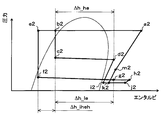
- the inlet / outlet enthalpy difference in the low-stage evaporator 18 is ⁇ h_le as shown in FIG.
- the inlet / outlet enthalpy difference in the low-stage evaporator 18 increases to ⁇ h_le + ⁇ h_iheh.
- the COP improvement effect can be obtained by setting the flow rate ratio Ge / Gn to a small value (that is, making the suction refrigerant flow rate Ge smaller than the injection refrigerant flow rate Gn) and increasing the pressure of the mixed refrigerant in the diffuser portion 19d. Even if it is sufficiently obtained, it is possible to suppress a decrease in the cooling capacity exhibited by the low-stage evaporator 18.
- F1 Can be brought closer.
- ⁇ h_he is an inlet / outlet enthalpy difference in the high-stage evaporator 18.
- the inlet / outlet in the lower-stage evaporator 18 than the comparative cycle in addition to being able to obtain a COP improvement effect by increasing the pressure of the mixed refrigerant in the diffuser portion 19d, the inlet / outlet in the lower-stage evaporator 18 than the comparative cycle.
- the COP improvement effect by enlarging the enthalpy difference can be obtained.
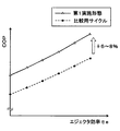
- the COP in the ejector refrigeration cycle 10 of the present embodiment, can be improved by about 6 to 8% compared to the comparative cycle.
- the horizontal axis in FIG. 4 indicates the ejector efficiency, which is the energy conversion efficiency of the ejector, and is a value that varies depending on the operating conditions of the ejector refrigeration cycle 10, the dimensions of the ejector 19, and the like.
- the COP improvement effect by the ejector refrigeration cycle 10 of the present embodiment can be obtained under a wide range of operating conditions of the ejector refrigeration cycle 10, and the ejector refrigeration cycle 10 has a wide range of dimensions. It is also possible to obtain the same ejector 19.
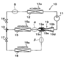
- the internal heat exchanger 16 of this embodiment includes a high-stage low-pressure refrigerant that flows through a refrigerant flow path from the refrigerant outlet side of the high-stage evaporator 15 to the inlet side of the nozzle portion 19a of the ejector 19, and a branching section. 13 performs the function of exchanging heat with the high-pressure refrigerant flowing through the refrigerant flow path from the other refrigerant outlet to the inlet side of the low-stage expansion device 17.
- the refrigerant outlet of the low-stage evaporator 18 and the refrigerant suction port 19c of the ejector 19 are directly connected via the refrigerant pipe.
- Other configurations are the same as those of the first embodiment.
- symbol in the Mollier diagram of FIG. 6 is the same about what shows the state of the refrigerant
- the alphabet is used and the subscripts (numbers) are changed. The same applies to the following Mollier diagram.
- the branching unit 13 branches.
- One refrigerant branched by the branching section 13 is decompressed by the high stage side expansion device 14 and then flows into the high stage side evaporator 15 to absorb heat from the indoor blast air and evaporate (see FIG. 6).
- b6 point ⁇ c6 point ⁇ d6 point Thereby, the indoor blowing air is cooled.
- the high-stage low-pressure refrigerant that has flowed out of the high-stage evaporator 15 flows into the low-pressure side refrigerant passage 16b of the internal heat exchanger 16, and passes through the high-pressure side refrigerant passage 16a of the internal heat exchanger 16.
- the enthalpy is raised by exchanging heat with the other refrigerant branched at the branching portion 13 that circulates (point d6 ⁇ point h6 in FIG. 6).
- the other refrigerant branched at the branching section 13 flows into the high-pressure side refrigerant passage 16a of the internal heat exchanger 16, and flows out of the high-stage evaporator 15 flowing through the low-pressure side refrigerant passage 16b of the internal heat exchanger 16. Heat exchange with the refrigerant reduces the enthalpy (b6 point ⁇ e6 point in FIG. 6).
- the refrigerant that has flowed out of the high-pressure side refrigerant passage 16a of the internal heat exchanger 16 is decompressed by the low-stage side expansion device 17, and then flows into the low-stage side evaporator 18, where it absorbs heat from the blown air for storage and evaporates. (E6 point ⁇ f6 point ⁇ g6 point in FIG. 6). As a result, the internal blown air is cooled.
- the refrigerant that has flowed out of the low-pressure side refrigerant passage 16b of the internal heat exchanger 16 flows into the nozzle portion 19a of the ejector 19 and is isentropically decompressed and injected (point h6 in FIG. 6). ⁇ i6 points).
- coolant g6 point of FIG. 6
- coolant (g6 point of FIG. 6) of the low stage side evaporator 18 is attracted
- the refrigerant injected from the nozzle portion 19a and the suction refrigerant sucked from the refrigerant suction port 19c flow into the diffuser portion 19d of the ejector 19 (i6 ⁇ k6 point, g6 point ⁇ j6 point ⁇ k6 point in FIG. 6). ).
- the velocity energy of the refrigerant is converted into pressure energy, and the pressure of the mixed refrigerant increases (k6 point ⁇ m6 point in FIG. 6). Subsequent operations are the same as those in the first embodiment.
- the vehicle interior and the refrigerator can be cooled at different temperature zones as in the first embodiment, and the internal heat exchanger 16 can be The cooling ability exhibited by the side evaporator 15 and the cooling ability exhibited by the low-stage evaporator 18 can be brought close to each other.
- the enthalpy of the refrigerant flowing into the nozzle portion 19a of the ejector 19 can be raised by the action of the internal heat exchanger 16 by the amount indicated by ⁇ h_ihel in FIG.
- the pressure of the refrigerant can be increased efficiently.
- the ejector 19 collects the loss of velocity energy when the refrigerant is decompressed by the nozzle portion 19a by sucking the refrigerant by the suction action of the injected refrigerant.
- the diffuser portion 19d converts the velocity energy of the mixed refrigerant into pressure energy. Therefore, the amount of pressure increase ⁇ P in the diffuser portion 19d can be increased by increasing the amount of speed energy to be recovered (recovered energy amount).
- the amount of energy recovered by the nozzle portion 19a is the difference between the enthalpy of the enthalpy of the nozzle side 19a inlet side refrigerant (point h6 in FIG. 6) and the enthalpy of the nozzle portion 19a outlet side refrigerant (point i6 in FIG. 6). ( ⁇ H6 in FIG. 6).
- the amount of recovered energy can be increased when the refrigerant is isentropically expanded by a predetermined pressure at the nozzle portion 19a.
- the mixed refrigerant can be efficiently boosted by the diffuser portion 19d.
- the pressure increase ⁇ P in the diffuser portion 19d is increased without increasing the flow rate ratio Ge / Gn, and the mixed refrigerant is boosted in the diffuser portion 19d.
- a sufficient COP improvement effect can be obtained.
- the adjustable range of the flow rate ratio Ge / Gn can be expanded, so that the cooling capacity exhibited by each of the evaporators 15 and 18 is appropriately adjusted. can do.
- the internal heat exchanger 16 of the present embodiment includes a high-stage low-pressure refrigerant that flows through a refrigerant flow path from the refrigerant outlet side of the high-stage evaporator 15 to the inlet side of the nozzle portion 19a of the ejector 19, and a radiator.
- the high-pressure refrigerant flowing through the refrigerant flow path from the refrigerant outlet side of 12 to the inlet side of the branch portion 13 is exchanged.
- the inlet side of the high stage side throttle device 14 is connected to one refrigerant outlet of the branching portion 13, and the inlet side of the low stage side throttle device 17 is connected to the other refrigerant outlet of the branching portion 13. It is connected.
- Other configurations are the same as those of the second embodiment.
- the high-pressure refrigerant flowing out from the radiator 12 flows into the high-pressure side refrigerant passage 16a of the internal heat exchanger 16 and flows through the low-pressure side refrigerant passage 16b of the internal heat exchanger 16.
- the enthalpy is reduced by exchanging heat with the refrigerant flowing out of the vessel 15 (b8 point ⁇ e8 point in FIG. 8).
- the flow of the refrigerant flowing out from the high-pressure side refrigerant passage 16a is branched at the branching section 13.
- One refrigerant branched by the branching section 13 is decompressed by the high stage side expansion device 14 and then flows into the high stage side evaporator 15 and absorbs heat from the indoor blown air, as in the first embodiment. And evaporate (point e8 ⁇ point c8 ⁇ point d8 in FIG. 8). Thereby, the indoor blowing air is cooled.
- the high-stage low-pressure refrigerant that has flowed out of the high-stage evaporator 15 flows into the low-pressure side refrigerant passage 16b of the internal heat exchanger 16, and passes through the high-pressure side refrigerant passage 16a of the internal heat exchanger 16.
- the enthalpy is raised by exchanging heat with the other refrigerant branched at the branching portion 13 that circulates (point d8 ⁇ point h8 in FIG. 8).
- the other refrigerant branched by the branching section 13 is decompressed by the low stage side expansion device 17 and then flows into the low stage side evaporator 18 and absorbs heat from the blown air inside the warehouse to evaporate (FIG. 8). E8 point ⁇ f8 point ⁇ g8 point). As a result, the internal blown air is cooled.
- the refrigerant that has flowed out of the low-pressure side refrigerant passage 16b of the internal heat exchanger 16 flows into the nozzle portion 19a of the ejector 19 and is isentropically decompressed and injected. (Point h8 ⁇ point i8 in FIG. 8). Then, the refrigerant on the downstream side of the low-stage evaporator 18 (g8 point in FIG. 8) is sucked from the refrigerant suction port 19c of the ejector 19 by the suction action of the injection refrigerant. Subsequent operations are the same as those in the second embodiment.
- the vehicle interior and the refrigerator can be cooled at different temperature zones as in the first embodiment. Further, as in the second embodiment, the amount of recovered energy in the nozzle portion 19a (corresponding to ⁇ H8 in FIG. 8) can be increased, and the mixed refrigerant can be efficiently boosted in the diffuser portion 19d.
- the cooling capacity exhibited by the evaporators 15 and 18 can be adjusted appropriately.
- the internal heat exchanger 16 is connected so that the cooling ability exhibited by the high-stage evaporator 15 and the cooling ability exhibited by the low-stage evaporator 18 are close to each other.
- the connection mode of the internal heat exchanger 16 is not limited to this. That is, if the cooling capacity exhibited by each of the evaporators 15 and 18 can be adjusted, the internal heat exchanger 16 can use a low-pressure refrigerant and a high-pressure refrigerant that are different from the combinations disclosed in the above-described embodiments. Heat exchange may be performed.
- the high-pressure refrigerant in the region X high-pressure refrigerant flowing through the refrigerant flow path from the refrigerant outlet side of the radiator 12 to the inlet side of the branching portion 13
- the high-pressure refrigerant in the region Y branching portion 13
- high-pressure refrigerant flowing through the refrigerant flow path from one refrigerant outlet to the inlet side of the high-stage throttle device 14, and high-pressure refrigerant in the region Z from the other refrigerant outlet of the branch portion 13 to the low-stage throttle
- One may be heat exchanged by the internal heat exchanger 16.
- the cooling ability exhibited by the high-stage evaporator 15 is reduced by the low-stage evaporator 18. It can adjust so that it may become larger than the cooling capacity exhibited. Further, heat exchange may be performed between the high-pressure refrigerant in the region X and the low-pressure refrigerant in the region ⁇ .
- the inlet side of the high stage side throttle device 14 is connected to one refrigerant outlet of the branch portion 13, and the inlet of the low stage side throttle device 14 is connected to the other refrigerant outlet of the branch portion 13.
- the ejector refrigeration cycle 10 to which the side is connected has been described, the cycle configuration of the ejector refrigeration cycle of the present disclosure is not limited to this.
- the inlet side of the high stage side throttle device 14 is connected to the refrigerant outlet side of the radiator 12, and the inlet side of the branch portion 13 is connected to the outlet side of the high stage side throttle device 14.
- the refrigerant inlet side of the high-stage evaporator 15 is connected to one refrigerant outlet of the refrigerant 13, and the refrigerant of the low-stage evaporator 18 is connected to the other refrigerant outlet of the branch part 13 via the low-stage throttle device 17.
- a cycle configuration in which the inlet side is connected may be used.
- the internal heat exchanger 16 uses the high-pressure refrigerant in the region S in FIG. 10 (the refrigerant flow path from the refrigerant outlet side of the radiator 12 to the inlet side of the high-stage expansion device 14). What is necessary is just to heat-exchange the high-pressure refrigerant
- the ejector-type refrigeration cycle 10 including the two evaporators 15 and 18 that evaporate the refrigerant in different temperature ranges has been described.
- another evaporator may be provided. This other evaporator may be connected in parallel to the high-stage evaporator 15 or the low-stage evaporator 18, or the high-stage evaporator 15 or the low-stage evaporator 18. May be connected in series.
- the front-seat blown air that is blown to the front seat side of the vehicle by the high-stage evaporator 15 is cooled and blown to the rear-seat side of the vehicle by the low-stage evaporator 18.
- the present invention may be applied to a so-called dual air conditioner system that cools the rear-seat blown air.
- the present invention is not limited to vehicles, and may be applied to stationary refrigeration / freezers, showcases, air conditioners, and the like.
- the low-temperature side cooling target space whose temperature is desired to be lowered is cooled by the low-stage evaporator 18 and cooled in a higher temperature zone than the low-temperature side cooling target space.
- the target space may be cooled by the high-stage evaporator 15.
- Components constituting the ejector refrigeration cycle 10 are not limited to those disclosed in the above-described embodiment.
- an engine-driven compressor driven by a rotational driving force transmitted from an engine (internal combustion engine) via a pulley, a belt, or the like may be employed.
- This type of engine-driven compressor includes a variable displacement compressor that can adjust the refrigerant discharge capacity by changing the discharge capacity, and a fixed type that adjusts the refrigerant discharge capacity by changing the operating rate of the compressor by intermittently connecting the electromagnetic clutch.
- a capacity type compressor or the like can be employed.
- a condensing part that condenses the refrigerant discharged from the compressor 11 by exchanging heat between the refrigerant discharged from the compressor 11 and the outside air, a modulator part that separates the gas-liquid of the refrigerant flowing out from the condensing part, and a modulator part A so-called subcool type condenser configured to have a supercooling unit that supercools the liquid phase refrigerant by exchanging heat between the liquid phase refrigerant flowing out from the outside air and the outside air may be adopted.
- a valve body configured to be able to change the throttle opening degree and an electric actuator composed of a stepping motor that changes the throttle opening degree of the valve body.
- An electric variable aperture mechanism configured as described above may be employed.
- the high-pressure refrigerant and the low-pressure refrigerant can exchange heat by brazing and joining the refrigerant pipe forming the high-pressure side refrigerant passage 16a and the refrigerant pipe forming the low-pressure side refrigerant passage 16b.
- the configuration described above may be adopted.
- the internal heat exchanger 16 may have a configuration in which a plurality of tubes forming the high-pressure side refrigerant passage 16a are provided and the low-pressure side refrigerant passage 16b is formed between adjacent tubes.
- R600a is adopted as the refrigerant
- the refrigerant is not limited to this.
- R134a, R1234yf, R410A, R404A, R32, R1234yfxf, R407C, etc. can be employed.
Abstract
An ejector refrigeration cycle, wherein: an inlet of a nozzle portion (19a) of an ejector (19) is connected to a refrigerant discharge side of a higher-stage evaporator (15); a refrigerant suction port (19c) of the ejector (19) is connected to the refrigerant discharge side of a lower-stage evaporator (18); and an internal heat exchanger (16) is provided in which high-pressure refrigerant flowing to a lower-stage throttling device (17) for lowering the pressure of refrigerant flowing to the lower-stage evaporator (18) exchanges heat with lower-stage, low-pressure refrigerant flowing out from the lower-stage evaporator (18). Thus, because the outlet/inlet enthalpy difference in the lower-stage evaporator (18) can be increased, the cooling capacities exhibited by the evaporators (15, 18) can be made close to each other even if the flow ratio (Ge/Gn) of the intake refrigerant flow rate (Ge) to the injection refrigerant flow rate (Gn) is set to a comparatively small value to improve the COP for the cycle.
Description
本出願は、当該開示内容が参照によって本出願に組み込まれた、2014年5月30日に出願された日本特許出願2014-112156を基にしている。
This application is based on Japanese Patent Application 2014-112156 filed on May 30, 2014, the disclosure of which is incorporated herein by reference.
本開示は、異なる温度帯で冷媒を蒸発させる複数の蒸発器を備えるエジェクタ式冷凍サイクルに関する。
The present disclosure relates to an ejector-type refrigeration cycle including a plurality of evaporators that evaporate a refrigerant in different temperature zones.
従来、エジェクタを備える蒸気圧縮式の冷凍サイクル装置であるエジェクタ式冷凍サイクルが知られている。
Conventionally, an ejector-type refrigeration cycle, which is a vapor compression refrigeration cycle apparatus including an ejector, is known.
この種のエジェクタ式冷凍サイクルでは、エジェクタのノズル部から噴射された高速度の噴射冷媒の吸引作用によって蒸発器から流出した冷媒をエジェクタの冷媒吸引口から吸引し、エジェクタのディフューザ部(昇圧部)にて噴射冷媒と吸引冷媒との混合冷媒を昇圧させ、さらに、ディフューザ部にて昇圧された混合冷媒を圧縮機へ吸入させる。
In this type of ejector-type refrigeration cycle, the refrigerant that has flowed out of the evaporator due to the suction action of the high-speed jet refrigerant injected from the nozzle portion of the ejector is sucked from the refrigerant suction port of the ejector, and the diffuser portion (pressure booster) of the ejector The pressure of the mixed refrigerant of the injection refrigerant and the suction refrigerant is increased in step, and the mixed refrigerant whose pressure is increased in the diffuser section is sucked into the compressor.
これにより、エジェクタ式冷凍サイクルでは、蒸発器における冷媒蒸発圧力と圧縮機の吸入冷媒圧力が略同等となる通常の冷凍サイクル装置よりも、圧縮機の消費動力を低減させ、サイクルの成績係数(COP)を向上させることができる。
As a result, in the ejector refrigeration cycle, the power consumption of the compressor is reduced and the coefficient of performance (COP) of the cycle is reduced compared to a normal refrigeration cycle apparatus in which the refrigerant evaporation pressure in the evaporator and the suction refrigerant pressure in the compressor are substantially equal. ) Can be improved.
さらに、特許文献1には、この種のエジェクタ式冷凍サイクルとして、2つの蒸発器を備え、一方の蒸発器(第1蒸発器)から流出した冷媒をエジェクタのノズル部へ流入させ、他方の蒸発器(第2蒸発器)から流出した冷媒を冷媒吸引口から吸引させるサイクル構成のものが開示されている。
Further, Patent Document 1 includes two evaporators as this type of ejector-type refrigeration cycle, and the refrigerant flowing out from one evaporator (first evaporator) flows into the nozzle portion of the ejector and the other is evaporated. The thing of the cycle structure which attracts | sucks the refrigerant | coolant which flowed out from the container (2nd evaporator) from the refrigerant | coolant suction port is disclosed.
この特許文献1のエジェクタ式冷凍サイクルでは、第1蒸発器における冷媒蒸発温度と第2蒸発器における冷媒蒸発温度が異なる温度帯となる。そこで、特許文献1では、このエジェクタ式冷凍サイクルを保冷装置に適用し、第1蒸発器および第2蒸発器を、それぞれ異なる保冷室(冷却対象空間)に配置して、それぞれの保冷室内を異なる温度帯で保冷できるようにしている。
In the ejector refrigeration cycle of Patent Document 1, the refrigerant evaporation temperature in the first evaporator and the refrigerant evaporation temperature in the second evaporator are in different temperature zones. Therefore, in Patent Document 1, this ejector refrigeration cycle is applied to a cold insulation device, and the first evaporator and the second evaporator are arranged in different cold insulation chambers (cooling target spaces), and the respective cold insulation chambers are different. The temperature can be kept cool.
ところで、特許文献1の保冷装置のように、それぞれの蒸発器にて異なる冷却対象空間を冷却する構成では、それぞれの冷却対象空間の容積等に応じて、それぞれの蒸発器に要求される冷却能力が異なる。ここで、冷却能力とは、蒸発器の出口側冷媒のエンタルピから蒸発器の入口側冷媒のエンタルピを減算したエンタルピ差と蒸発器を流通する冷媒流量(質量流量)との積算値によって定義することができる。
By the way, in the structure which cools the cooling object space which is different in each evaporator like the cooling device of patent document 1, according to the volume etc. of each cooling object space, the cooling capacity requested | required of each evaporator Is different. Here, the cooling capacity is defined by the integrated value of the enthalpy difference obtained by subtracting the enthalpy of the refrigerant on the inlet side of the evaporator from the enthalpy of the refrigerant on the outlet side of the evaporator and the refrigerant flow rate (mass flow rate) flowing through the evaporator. Can do.
また、一般的なエジェクタでは、噴射冷媒の吸引作用によって冷媒を吸引することで、ノズル部にて冷媒が減圧される際の速度エネルギの損失を回収している。そして、ディフューザ部にて噴射冷媒と吸引冷媒との混合冷媒の速度エネルギを圧力エネルギに変換することによって、混合冷媒を昇圧させている。
Further, in a general ejector, the refrigerant is sucked by the sucking action of the jetted refrigerant, thereby recovering the speed energy loss when the refrigerant is decompressed at the nozzle portion. Then, the mixed refrigerant is pressurized by converting the velocity energy of the mixed refrigerant of the injected refrigerant and the suction refrigerant into pressure energy in the diffuser section.
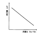
従って、特許文献1のエジェクタ式冷凍サイクルにおいても、噴射冷媒流量Gnに対する吸引冷媒流量Geの流量比Ge/Gnを小さくするに伴って、噴射冷媒(混合冷媒)の流速を増加させて、ディフューザ部における昇圧量ΔPを増加させることができる。つまり、流量比Ge/Gnを小さくするに伴って、ディフューザ部にて混合冷媒を昇圧させることによるCOP向上効果を得やすくなる。
Therefore, also in the ejector type refrigeration cycle of Patent Document 1, as the flow rate ratio Ge / Gn of the suction refrigerant flow rate Ge to the injection refrigerant flow rate Gn is reduced, the flow rate of the injection refrigerant (mixed refrigerant) is increased, and the diffuser portion The amount of pressure increase ΔP can be increased. That is, as the flow rate ratio Ge / Gn is reduced, it becomes easier to obtain a COP improvement effect by increasing the pressure of the mixed refrigerant in the diffuser section.
ところが、流量比Ge/Gnを小さくすると、第2蒸発器を流通する冷媒流量が減少してしまうので、第2蒸発器にて発揮される冷却能力が第1蒸発器にて発揮される冷却能力よりも低下してしまう。逆に、流量比Ge/Gnを大きくすると、第2蒸発器にて発揮される冷却能力と第1蒸発器にて発揮される冷却能力を近づけることはできるものの、昇圧量ΔPが減少してしまうので、COP向上効果を得にくくなってしまう。
However, if the flow rate ratio Ge / Gn is reduced, the flow rate of the refrigerant flowing through the second evaporator decreases, so that the cooling capacity exhibited by the second evaporator is the cooling capacity exhibited by the first evaporator. It will be lower than. On the contrary, when the flow ratio Ge / Gn is increased, the cooling capacity exhibited by the second evaporator can be brought closer to the cooling capacity exhibited by the first evaporator, but the pressure increase amount ΔP decreases. Therefore, it becomes difficult to obtain the COP improvement effect.
つまり、特許文献1のように複数の蒸発器を備えるエジェクタ式冷凍サイクルでは、ディフューザ部にて混合冷媒を昇圧させることによるCOP向上効果を充分に得つつ、それぞれの蒸発器にて発揮される冷却能力を、用途に応じて要求される冷却能力となるように調整することが難しい。
In other words, in an ejector-type refrigeration cycle having a plurality of evaporators as in Patent Document 1, a cooling effect exhibited by each evaporator is obtained while sufficiently obtaining a COP improvement effect by increasing the pressure of the mixed refrigerant in the diffuser section. It is difficult to adjust the capacity so that the cooling capacity required according to the application is obtained.
特に、昇圧量ΔPを増加させるために流量比Ge/Gnを小さくしてしまうと、COP向上効果を充分に得つつ、それぞれの蒸発器にて発揮される冷却能力を同等となるように調整することは難しい。
In particular, if the flow rate ratio Ge / Gn is reduced in order to increase the pressure increase amount ΔP, the COP improvement effect is sufficiently obtained and the cooling capacity exhibited by each evaporator is adjusted to be equal. It ’s difficult.
本開示は、上記点に鑑み、異なる温度帯で冷媒を蒸発させる複数の蒸発器を備えるエジェクタ式冷凍サイクルにおいて、それぞれの蒸発器にて発揮される冷却能力を調整可能とすることを第1の目的とする。
In view of the above points, the present disclosure provides a first feature that in a ejector refrigeration cycle including a plurality of evaporators that evaporate a refrigerant in different temperature zones, the cooling capacity exhibited by each evaporator can be adjusted. Objective.
また、本開示は、異なる温度帯で冷媒を蒸発させる複数の蒸発器を備えるエジェクタ式冷凍サイクルにおいて、それぞれの蒸発器にて発揮される冷却能力を近づけることを第2の目的とする。
Also, a second object of the present disclosure is to bring the cooling capacity exhibited by each evaporator closer in an ejector refrigeration cycle including a plurality of evaporators that evaporate a refrigerant in different temperature zones.
本開示の一つの特徴例によるエジェクタ式冷凍サイクルは、冷媒を圧縮して吐出する圧縮機と、圧縮機から吐出された冷媒を放熱させる放熱器と、放熱器から流出した冷媒を減圧させる第1減圧装置および第2減圧装置と、第1減圧装置にて減圧された冷媒を蒸発させる第1蒸発器と、第2減圧装置にて減圧された冷媒を蒸発させる第2蒸発器と、第1蒸発器から流出した冷媒を減圧させるノズル部から噴射される高速度の噴射冷媒の吸引作用によって冷媒吸引口から第2蒸発器下流側冷媒を吸引し、噴射冷媒と冷媒吸引口から吸引された吸引冷媒とを混合させて昇圧させるエジェクタと、を備える。さらに、エジェクタ式冷凍サイクルは、(i)放熱器の冷媒出口側から第1減圧装置の入口側へ至る冷媒流路、および放熱器の冷媒出口側から第2減圧装置の入口側へ至る冷媒流路のうち、少なくとも一方の冷媒流路を流通する冷媒を高圧冷媒とし、(ii)第1蒸発器の冷媒出口側からノズル部の入口側へ至る冷媒流路を流通する冷媒を高段側低圧冷媒とし、(iii)第2蒸発器の冷媒出口側から冷媒吸引口へ至る冷媒流路を流通する冷媒を低段側低圧冷媒とした場合において、高段側低圧冷媒および低段側低圧冷媒のうちいずれか一方と高圧冷媒とを熱交換させる内部熱交換器を備える。
An ejector-type refrigeration cycle according to one characteristic example of the present disclosure includes a compressor that compresses and discharges a refrigerant, a radiator that dissipates heat from the refrigerant discharged from the compressor, and a first that depressurizes refrigerant that flows out of the radiator. A decompressor and a second decompressor, a first evaporator that evaporates the refrigerant decompressed by the first decompressor, a second evaporator that evaporates the refrigerant decompressed by the second decompressor, and the first evaporation Refrigerant sucked from the refrigerant suction port by the suction action of the high-speed jet refrigerant jetted from the nozzle part that decompresses the refrigerant flowing out of the evaporator, and sucked from the jet refrigerant and the refrigerant suction port And an ejector for mixing and boosting. Further, the ejector-type refrigeration cycle includes (i) a refrigerant flow path from the refrigerant outlet side of the radiator to the inlet side of the first decompressor, and a refrigerant flow from the refrigerant outlet side of the radiator to the inlet side of the second decompressor. Among the passages, the refrigerant flowing through at least one of the refrigerant flow paths is a high-pressure refrigerant, and (ii) the refrigerant flowing through the refrigerant flow path from the refrigerant outlet side of the first evaporator to the inlet side of the nozzle portion is the high-stage low pressure (Iii) When the refrigerant flowing through the refrigerant flow path from the refrigerant outlet side of the second evaporator to the refrigerant suction port is a low-stage low-pressure refrigerant, the high-stage low-pressure refrigerant and the low-stage low-pressure refrigerant An internal heat exchanger for exchanging heat between any one of them and the high-pressure refrigerant is provided.
これによれば、第1蒸発器から流出した冷媒をエジェクタのノズル部へ流入させ、第2蒸発器から流出した冷媒をエジェクタの冷媒吸引口から吸引させるので、第2蒸発器における冷媒蒸発温度を第1蒸発器における冷媒蒸発温度よりも低い温度帯とすることができる。
According to this, since the refrigerant flowing out from the first evaporator flows into the nozzle portion of the ejector and the refrigerant flowing out from the second evaporator is sucked from the refrigerant suction port of the ejector, the refrigerant evaporation temperature in the second evaporator is set. It can be set as the temperature range lower than the refrigerant | coolant evaporation temperature in a 1st evaporator.
さらに、エジェクタ式冷凍サイクルは、高段側低圧冷媒および低段側低圧冷媒のうちいずれか一方と、高圧冷媒とを熱交換させる内部熱交換器を備えている。
Furthermore, the ejector refrigeration cycle includes an internal heat exchanger that exchanges heat between either the high-stage low-pressure refrigerant or the low-stage low-pressure refrigerant and the high-pressure refrigerant.
従って、各蒸発器の出口側冷媒のエンタルピから各蒸発器の入口側冷媒のエンタルピを減算したエンタルピ差(以下、単に、各蒸発器における出入口エンタルピ差と記載する。)を調整することや、ノズル部へ流入させる冷媒のエンタルピを上昇させることが可能となり、それぞれの蒸発器にて発揮される冷却能力を調整することができる。
Therefore, it is possible to adjust an enthalpy difference obtained by subtracting the enthalpy of the inlet side refrigerant of each evaporator from the enthalpy of the outlet side refrigerant of each evaporator (hereinafter simply referred to as an inlet / outlet enthalpy difference in each evaporator), or a nozzle. It is possible to increase the enthalpy of the refrigerant flowing into the section, and the cooling capacity exhibited by each evaporator can be adjusted.
例えば、エジェクタ式冷凍サイクルは、放熱器から流出した冷媒の流れを分岐する分岐部を備え、分岐部の一方の冷媒流出口には、第1減圧装置の入口側が接続されており、分岐部の他方の冷媒流出口には、第2減圧装置の入口側が接続されており、内部熱交換器は、低段側低圧冷媒と、分岐部の他方の冷媒流出口から第2減圧装置の入口側へ至る冷媒流路を流通する高圧冷媒とを熱交換させるものであってもよい。
For example, an ejector-type refrigeration cycle includes a branch part that branches the flow of refrigerant that has flowed out of a radiator, and the inlet side of the first decompression device is connected to one refrigerant outlet of the branch part. The other refrigerant outlet is connected to the inlet side of the second decompression device, and the internal heat exchanger includes a low-stage low-pressure refrigerant and the other refrigerant outlet of the branch portion to the inlet side of the second decompression device. Heat exchange may be performed with the high-pressure refrigerant flowing through the refrigerant flow path.
これによれば、内部熱交換器にて、分岐部の他方の冷媒流出口から第2減圧装置の入口側へ至る冷媒流路を流通する高圧冷媒を冷却することができるので、第2蒸発器における出入口エンタルピ差を拡大することができる。
According to this, since the internal heat exchanger can cool the high-pressure refrigerant flowing through the refrigerant flow path from the other refrigerant outlet of the branch portion to the inlet side of the second decompression device, the second evaporator The entrance and exit enthalpy difference at can be expanded.
従って、エジェクタ式冷凍サイクルの成績係数を向上させるために、前述した噴射冷媒流量Gnに対する吸引冷媒流量Geの流量比Ge/Gnを小さくしても、第1蒸発器にて発揮される冷却能力と第2蒸発器にて発揮される冷却能力とを近づけることができる。
Therefore, in order to improve the coefficient of performance of the ejector-type refrigeration cycle, even if the flow rate ratio Ge / Gn of the suction refrigerant flow rate Ge to the injection refrigerant flow rate Gn described above is reduced, The cooling capacity exhibited by the second evaporator can be approached.
あるいは、エジェクタ式冷凍サイクルは、放熱器から流出した冷媒の流れを分岐する分岐部を備え、分岐部の一方の冷媒流出口には、第1減圧装置の入口側が接続されており、分岐部の他方の冷媒流出口には、第2減圧装置の入口側が接続されており、内部熱交換器は、高段側低圧冷媒と、分岐部の他方の冷媒流出口から第2減圧装置の入口側へ至る冷媒流路を流通する高圧冷媒とを熱交換させるものであってもよい。
Alternatively, the ejector refrigeration cycle includes a branch portion that branches the flow of the refrigerant that has flowed out of the radiator, and the inlet side of the first decompression device is connected to one refrigerant outlet of the branch portion. The other refrigerant outlet is connected to the inlet side of the second decompression device, and the internal heat exchanger has a high-stage low-pressure refrigerant and the other refrigerant outlet of the branch portion to the inlet side of the second decompression device. Heat exchange may be performed with the high-pressure refrigerant flowing through the refrigerant flow path.
これによれば、第1蒸発器にて発揮される冷却能力と第2蒸発器にて発揮される冷却能力とを近づけることができる。さらに、内部熱交換器にて、高段側低圧冷媒を加熱して、エジェクタのノズル部へ流入させる冷媒のエンタルピを上昇させることができる。
According to this, the cooling capacity exhibited by the first evaporator and the cooling capacity exhibited by the second evaporator can be brought close to each other. Furthermore, the enthalpy of the refrigerant flowing into the nozzle portion of the ejector can be increased by heating the high-stage low-pressure refrigerant in the internal heat exchanger.
従って、エジェクタの回収エネルギ量を増加させることができ、流量比Ge/Gnを小さくしなくても、エジェクタの昇圧量ΔPを上昇させることができる。その結果、第1蒸発器にて発揮される冷却能力と第2蒸発器にて発揮される冷却能力とを近づけることができる。
Therefore, the amount of energy recovered by the ejector can be increased, and the boost amount ΔP of the ejector can be increased without reducing the flow rate ratio Ge / Gn. As a result, the cooling ability exhibited by the first evaporator and the cooling ability exhibited by the second evaporator can be brought close to each other.
或いは、エジェクタ式冷凍サイクルは、放熱器から流出した冷媒の流れを分岐する分岐部を備え、分岐部の一方の冷媒流出口には、第1減圧装置の入口側が接続されており、分岐部の他方の冷媒流出口には、第2減圧装置の入口側が接続されており、内部熱交換器は、高段側低圧冷媒と、放熱器の冷媒出口側から分岐部の入口側へ至る冷媒流路を流通する高圧冷媒とを熱交換させるものであってもよい。
Alternatively, the ejector refrigeration cycle includes a branch portion that branches the flow of the refrigerant that has flowed out of the radiator, and the inlet side of the first decompression device is connected to one refrigerant outlet of the branch portion. The other refrigerant outlet is connected to the inlet side of the second decompression device, and the internal heat exchanger includes a high-stage low-pressure refrigerant and a refrigerant flow path from the refrigerant outlet side of the radiator to the inlet side of the branch portion. It is possible to exchange heat with a high-pressure refrigerant that circulates.
これによれば、内部熱交換器にて、高段側低圧冷媒を加熱することで、第1蒸発器にて発揮される冷却能力と第2蒸発器にて発揮される冷却能力とを近づけることができる。
According to this, by heating the high-stage low-pressure refrigerant in the internal heat exchanger, the cooling capacity exhibited by the first evaporator and the cooling capacity exhibited by the second evaporator are brought close to each other. Can do.
(第1実施形態)
図1~図4を用いて、第1実施形態について説明する。本実施形態では、本開示に係るエジェクタ式冷凍サイクル10を、冷蔵車両に搭載される車両用冷凍サイクル装置に適用している。この車両用冷凍サイクル装置は、冷蔵車両において、車室内へ送風される室内用送風空気を冷却する機能、および車両の荷台に配置された冷蔵庫内へ送風される庫内用送風空気を冷却する機能を担っている。 (First embodiment)
The first embodiment will be described with reference to FIGS. In the present embodiment, theejector refrigeration cycle 10 according to the present disclosure is applied to a vehicle refrigeration cycle apparatus mounted on a refrigerated vehicle. This refrigeration cycle device for a vehicle has a function of cooling indoor air blown into a vehicle compartment in a refrigerated vehicle, and a function of cooling internal blown air sent into a refrigerator arranged in a loading platform of the vehicle Is responsible.
図1~図4を用いて、第1実施形態について説明する。本実施形態では、本開示に係るエジェクタ式冷凍サイクル10を、冷蔵車両に搭載される車両用冷凍サイクル装置に適用している。この車両用冷凍サイクル装置は、冷蔵車両において、車室内へ送風される室内用送風空気を冷却する機能、および車両の荷台に配置された冷蔵庫内へ送風される庫内用送風空気を冷却する機能を担っている。 (First embodiment)
The first embodiment will be described with reference to FIGS. In the present embodiment, the
従って、本実施形態では、車室内空間および冷蔵庫内空間の双方が、エジェクタ式冷凍サイクル10の冷却対象空間となる。さらに、本実施形態では、車室内と冷蔵庫内の容積が略同等となっており、それぞれの冷却対象空間を冷却するために必要な冷却能力も同等なっている。
Therefore, in the present embodiment, both the vehicle interior space and the refrigerator internal space are cooling target spaces of the ejector refrigeration cycle 10. Furthermore, in this embodiment, the volume in a vehicle interior and a refrigerator is substantially equivalent, and the cooling capacity required in order to cool each cooling object space is also equivalent.
なお、本実施形態における冷却能力は、エジェクタ式冷凍サイクル10が備える蒸発器の出口側冷媒のエンタルピから蒸発器の入口側冷媒のエンタルピを減算したエンタルピ差(出入口エンタルピ差)と、当該蒸発器を流通する冷媒流量(質量流量)との積算値で定義される。
In addition, the cooling capacity in this embodiment is obtained by subtracting the enthalpy of the outlet side refrigerant of the evaporator provided in the ejector-type refrigeration cycle 10 from the enthalpy of the inlet side refrigerant of the evaporator (entrance / entrance difference). It is defined by an integrated value with the flow rate of refrigerant flowing (mass flow rate).
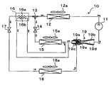
図1の全体構成図に示すエジェクタ式冷凍サイクル10において、圧縮機11は、冷媒を吸入し、圧縮して吐出するものである。具体的には、本実施形態の圧縮機11は、1つのハウジング内に固定容量型の圧縮機構、および圧縮機構を駆動する電動モータを収容して構成された電動圧縮機である。
In the ejector refrigeration cycle 10 shown in the overall configuration diagram of FIG. 1, the compressor 11 sucks in refrigerant, compresses it, and discharges it. Specifically, the compressor 11 of the present embodiment is an electric compressor configured by housing a fixed capacity type compression mechanism and an electric motor that drives the compression mechanism in one housing.
この圧縮機構としては、スクロール型圧縮機構、ベーン型圧縮機構等の各種圧縮機構を採用できる。また、電動モータは、後述する制御装置から出力される制御信号によって、その作動(回転数)が制御されるもので、交流モータ、直流モータのいずれの形式のものであってもよい。
As this compression mechanism, various compression mechanisms such as a scroll-type compression mechanism and a vane-type compression mechanism can be adopted. Further, the operation (rotation speed) of the electric motor is controlled by a control signal output from a control device to be described later, and any type of an AC motor and a DC motor may be used.
また、本実施形態のエジェクタ式冷凍サイクル10では、冷媒として自然冷媒(具体的には、R600a)を採用しており、高圧側の冷媒圧力が冷媒の臨界圧力を超えない蒸気圧縮式の亜臨界冷凍サイクルを構成している。さらに、冷媒には圧縮機11を潤滑するための冷凍機油が混入されており、冷凍機油の一部は冷媒とともにサイクルを循環している。
Further, in the ejector refrigeration cycle 10 of the present embodiment, a natural refrigerant (specifically, R600a) is adopted as the refrigerant, and the vapor compression subcriticality in which the high-pressure side refrigerant pressure does not exceed the refrigerant critical pressure. It constitutes the refrigeration cycle. Furthermore, refrigeration oil for lubricating the compressor 11 is mixed in the refrigerant, and a part of the refrigeration oil circulates in the cycle together with the refrigerant.
圧縮機11の吐出口には、放熱器12の冷媒入口側が接続されている。放熱器12は、圧縮機11から吐出された吐出冷媒と冷却ファン12aにより送風される車室外空気(外気)を熱交換させて、高圧冷媒を放熱させて冷却する放熱用熱交換器である。冷却ファン12aは、制御装置から出力される制御電圧によって回転数(送風空気量)が制御される電動式送風機である。
The refrigerant inlet side of the radiator 12 is connected to the discharge port of the compressor 11. The radiator 12 is a heat exchanger for radiating heat by exchanging heat between the refrigerant discharged from the compressor 11 and outside air (outside air) blown by the cooling fan 12a to radiate the high-pressure refrigerant. The cooling fan 12a is an electric blower in which the number of rotations (the amount of blown air) is controlled by a control voltage output from the control device.
放熱器12の冷媒出口側には、放熱器12から流出した冷媒の流れを分岐する分岐部13の冷媒流入口が接続されている。分岐部13は、3つの流入出口を有する三方継手で構成されており、3つの流入出口のうち1つを冷媒流入口とし、残りの2つを冷媒流出口としたものである。このような三方継手は、管径の異なる配管を接合して形成してもよいし、金属ブロックや樹脂ブロックに複数の冷媒通路を設けて形成してもよい。
The refrigerant outlet side of the radiator 12 is connected to the refrigerant inlet of the branching portion 13 that branches the flow of the refrigerant flowing out of the radiator 12. The branch portion 13 is configured by a three-way joint having three inflow / outflow ports, and one of the three inflow / outflow ports is a refrigerant inflow port, and the remaining two are refrigerant outflow ports. Such a three-way joint may be formed by joining pipes having different pipe diameters, or may be formed by providing a plurality of refrigerant passages in a metal block or a resin block.
分岐部13の一方の冷媒流出口には、第1減圧装置としての高段側絞り装置14の入口側が接続されている。高段側絞り装置14は、高段側蒸発器15出口側冷媒の温度および圧力に基づいて高段側蒸発器15出口側冷媒の過熱度を検出する感温部を有し、高段側蒸発器15出口側冷媒の過熱度が予め定めた基準範囲内となるように機械的機構によって絞り通路面積を調整する温度式膨張弁である。
The inlet side of a high-stage expansion device 14 as a first decompression device is connected to one refrigerant outlet of the branch part 13. The high stage side expansion device 14 includes a temperature sensing unit that detects the degree of superheat of the high stage side evaporator 15 outlet side refrigerant based on the temperature and pressure of the high stage side evaporator 15 outlet side refrigerant, This is a temperature type expansion valve that adjusts the throttle passage area by a mechanical mechanism so that the degree of superheat of the refrigerant on the outlet side of the container 15 is within a predetermined reference range.
高段側絞り装置14の出口側には、第1蒸発器としての高段側蒸発器15の冷媒入口側が接続されている。高段側蒸発器15は、高段側絞り装置14にて減圧された低圧冷媒と高段側送風ファン15aから車室内へ送風される室内用送風空気とを熱交換させて、低圧冷媒を蒸発させて吸熱作用を発揮させる吸熱用熱交換器である。
The refrigerant inlet side of the high stage evaporator 15 as the first evaporator is connected to the outlet side of the high stage side expansion device 14. The high-stage evaporator 15 evaporates the low-pressure refrigerant by exchanging heat between the low-pressure refrigerant decompressed by the high-stage side expansion device 14 and the indoor blown air blown into the vehicle interior from the high-stage blower fan 15a. This is an endothermic heat exchanger that exerts an endothermic effect.
高段側送風ファン15aは、制御装置から出力される制御電圧によって回転数(送風空気量)が制御される電動送風機である。高段側蒸発器15の冷媒出口側には、後述するエジェクタ19のノズル部19aの入口側が接続されている。
The high stage side blower fan 15a is an electric blower in which the rotation speed (the amount of blown air) is controlled by a control voltage output from the control device. An inlet side of a nozzle portion 19 a of an ejector 19 described later is connected to the refrigerant outlet side of the high stage evaporator 15.
分岐部13の他方の冷媒流出口には、内部熱交換器16の高圧側冷媒通路16aの入口側が接続されている。本実施形態の内部熱交換器16は、分岐部13の他方の冷媒流出口から流出した高圧冷媒と、後述する低段側蒸発器18から流出した低段側低圧冷媒とを熱交換させる機能を果たす。
The other refrigerant outlet of the branch part 13 is connected to the inlet side of the high-pressure side refrigerant passage 16a of the internal heat exchanger 16. The internal heat exchanger 16 of the present embodiment has a function of exchanging heat between the high-pressure refrigerant that has flowed out from the other refrigerant outlet of the branch portion 13 and the low-stage low-pressure refrigerant that has flowed out from the low-stage evaporator 18 described later. Fulfill.
このような内部熱交換器16としては、分岐部13の他方の冷媒流出口から流出した冷媒を流通させる高圧側冷媒通路16aを形成する外側管の内側に、低段側蒸発器18から流出した低段側低圧冷媒を流通させる低圧側冷媒通路16bを形成する内側管を配置した二重管方式の熱交換器等を採用することができる。
As such an internal heat exchanger 16, it flowed out of the low stage side evaporator 18 inside the outer pipe | tube which forms the high voltage | pressure side refrigerant path 16a which distribute | circulates the refrigerant | coolant which flowed out from the other refrigerant | coolant outflow port of the branch part 13. A double-pipe heat exchanger or the like in which an inner pipe that forms a low-pressure side refrigerant passage 16b through which the low-stage low-pressure refrigerant flows can be used.
内部熱交換器16の高圧側冷媒通路16aの出口側には、第2減圧装置としての低段側絞り装置17の入口側が接続されている。低段側絞り装置17は、絞り開度が固定された固定絞りであり、具体的には、ノズル、オリフィス、キャピラリチューブ等を採用することができる。
The inlet side of the low-stage expansion device 17 as the second decompression device is connected to the outlet side of the high-pressure side refrigerant passage 16a of the internal heat exchanger 16. The low-stage side throttle device 17 is a fixed throttle with a fixed throttle opening, and specifically, a nozzle, an orifice, a capillary tube, or the like can be adopted.
低段側絞り装置17の出口側には、第2蒸発器としての低段側蒸発器18の冷媒入口側が接続されている。低段側蒸発器18は、低段側絞り装置17にて減圧された低圧冷媒と低段側送風ファン18aから冷蔵庫内へ循環送風される庫内用送風空気とを熱交換させることによって、低圧冷媒を蒸発させて吸熱作用を発揮させる吸熱用熱交換器である。
The refrigerant inlet side of the low stage evaporator 18 as the second evaporator is connected to the outlet side of the low stage expansion device 17. The low-stage evaporator 18 exchanges heat between the low-pressure refrigerant decompressed by the low-stage side expansion device 17 and the internal blown air circulated into the refrigerator from the low-stage blower fan 18a. An endothermic heat exchanger that evaporates the refrigerant and exerts an endothermic effect.
低段側蒸発器18の基本的構成は、高段側蒸発器15と同等であり、低段側送風ファン18a基本的構成は、高段側送風ファン15aと同等である。低段側蒸発器18の冷媒出口側には、内部熱交換器16の低圧側冷媒通路16bの入口側が接続されている。さらに、低圧側冷媒通路16bの出口側には、後述するエジェクタ19の冷媒吸引口19c側が接続されている。
The basic configuration of the low-stage evaporator 18 is the same as that of the high-stage evaporator 15, and the basic configuration of the low-stage fan 18a is the same as that of the high-stage fan 15a. An inlet side of the low-pressure side refrigerant passage 16 b of the internal heat exchanger 16 is connected to the refrigerant outlet side of the low-stage evaporator 18. Furthermore, a refrigerant suction port 19c side of an ejector 19 described later is connected to the outlet side of the low-pressure side refrigerant passage 16b.
ここで、本実施形態の低段側絞り装置17の絞り開度は、サイクルの通常作動時における高段側絞り装置14の絞り開度よりも小さくなるように設定されている。従って、低段側蒸発器18における冷媒蒸発圧力(冷媒蒸発温度)は、高段側蒸発器15における冷媒蒸発圧力(冷媒蒸発温度)よりも低くなる。
Here, the throttle opening degree of the low stage side throttle device 17 of the present embodiment is set to be smaller than the throttle opening degree of the high stage side throttle device 14 during the normal operation of the cycle. Therefore, the refrigerant evaporation pressure (refrigerant evaporation temperature) in the low stage side evaporator 18 is lower than the refrigerant evaporation pressure (refrigerant evaporation temperature) in the high stage side evaporator 15.
さらに、本実施形態では、噴射冷媒流量Gnに対する吸引冷媒流量Geの流量比Ge/Gnが、1以下の予め定めた基準範囲内になるように、サイクルの通常作動時における高段側絞り装置14の絞り開度(流量特性)、低段側絞り装置17の絞り開度(流量特性)、分岐部13の各冷媒通路の通路断面積等が決定されている。
Further, in the present embodiment, the high stage side throttle device 14 during normal operation of the cycle is set so that the flow rate ratio Ge / Gn of the suction refrigerant flow rate Ge to the injection refrigerant flow rate Gn is within a predetermined reference range of 1 or less. The throttle opening degree (flow rate characteristic), the throttle opening degree (flow rate characteristic) of the low stage side throttle device 17, the passage cross-sectional area of each refrigerant passage of the branch portion 13, and the like are determined.
なお、噴射冷媒流量Gnとは、高段側絞り装置14および高段側蒸発器18を介してエジェクタ19のノズル部19aへ流入する冷媒流量(質量流量)である。また、吸引冷媒流量Geとは、内部熱交換器16の高圧側冷媒通路16a、低段側絞り装置17および低段側蒸発器18を介してエジェクタ19の冷媒吸引口19cから吸引される冷媒流量(質量流量)である。
The injected refrigerant flow rate Gn is a refrigerant flow rate (mass flow rate) flowing into the nozzle portion 19a of the ejector 19 via the high stage side expansion device 14 and the high stage side evaporator 18. The suction refrigerant flow rate Ge is a refrigerant flow rate sucked from the refrigerant suction port 19c of the ejector 19 through the high-pressure side refrigerant passage 16a, the low-stage side expansion device 17 and the low-stage side evaporator 18 of the internal heat exchanger 16. (Mass flow rate).
つまり、噴射冷媒流量Gnは、高段側蒸発器15を流通する冷媒流量であり、吸引冷媒流量Geは、低段側蒸発器18を流通する冷媒流量である。
That is, the injection refrigerant flow rate Gn is the refrigerant flow rate flowing through the high-stage evaporator 15, and the suction refrigerant flow rate Ge is the refrigerant flow rate flowing through the low-stage evaporator 18.
次に、エジェクタ19は、高段側蒸発器15から流出した冷媒を減圧させる減圧装置としての機能を果たすとともに、高速で噴射される噴射冷媒の吸引作用によって低段側蒸発器18から流出した冷媒を吸引(輸送)してサイクル内を循環させる冷媒循環部(冷媒輸送部)としての機能を果たすものである。
Next, the ejector 19 functions as a decompression device that depressurizes the refrigerant that has flowed out of the high-stage evaporator 15, and also flows out of the low-stage evaporator 18 by the suction action of the injected refrigerant that is injected at high speed. It functions as a refrigerant circulation section (refrigerant transport section) that sucks (transports) the refrigerant and circulates it in the cycle.
より具体的には、エジェクタ19、ノズル部19aおよびボデー部19bを有して構成されている。ノズル部19aは、冷媒の流れ方向に向かって徐々に先細る略円筒状の金属(例えば、ステンレス合金)等で形成されており、内部に形成された冷媒通路(絞り通路)にて冷媒を等エントロピ的に減圧膨張させるものである。
More specifically, it has an ejector 19, a nozzle part 19a and a body part 19b. The nozzle portion 19a is formed of a substantially cylindrical metal (for example, stainless steel alloy) or the like that gradually tapers in the refrigerant flow direction, and the like in the refrigerant passage (throttle passage) formed inside. It expands under reduced pressure entropy.
ノズル部19aの内部に形成された冷媒通路としては、通路断面積が最も縮小した喉部(最小通路面積部)が形成され、さらに、この喉部から冷媒を噴射する冷媒噴射口へ向かって冷媒通路面積が徐々に拡大する末広部が形成されている。つまり、ノズル部19aは、ラバールノズルとして構成されている。
As the refrigerant passage formed in the nozzle portion 19a, a throat portion (minimum passage area portion) having the smallest passage cross-sectional area is formed, and further, the refrigerant flows from the throat portion toward the refrigerant injection port for injecting the refrigerant. A divergent part in which the passage area gradually increases is formed. That is, the nozzle part 19a is configured as a Laval nozzle.
さらに、本実施形態では、ノズル部19aとして、エジェクタ式冷凍サイクル10の通常作動時に、冷媒噴射口から噴射される噴射冷媒の流速が音速以上となるように設定されたものが採用されている。もちろん、ノズル部19aを先細ノズルで構成してもよい。
Furthermore, in the present embodiment, the nozzle portion 19a is set such that the flow rate of the injected refrigerant injected from the refrigerant injection port is equal to or higher than the sonic speed during normal operation of the ejector refrigeration cycle 10. Of course, you may comprise the nozzle part 19a with a tapered nozzle.
ボデー部19bは、略円筒状の金属(例えば、アルミニウム)で形成されており、内部にノズル部19aを支持固定する固定部材として機能するとともに、エジェクタ19の外殻を形成するものである。より具体的には、ノズル部19aは、ボデー部19bの長手方向一端側の内部に収容されるように圧入にて固定されている。従って、ノズル部19aとボデー部19bとの固定部(圧入部)から冷媒が漏れることはない。
The body portion 19b is formed of a substantially cylindrical metal (for example, aluminum), functions as a fixing member that supports and fixes the nozzle portion 19a therein, and forms an outer shell of the ejector 19. More specifically, the nozzle portion 19a is fixed by press-fitting so as to be housed inside the longitudinal end of the body portion 19b. Therefore, the refrigerant does not leak from the fixed portion (press-fit portion) between the nozzle portion 19a and the body portion 19b.
また、ボデー部19bの外周面のうち、ノズル部19aの外周側に対応する部位には、その内外を貫通してノズル部19aの冷媒噴射口と連通するように設けられた冷媒吸引口19cが形成されている。この冷媒吸引口19cは、ノズル部19aから噴射される噴射冷媒の吸引作用によって、低段側蒸発器18から流出した冷媒をエジェクタ19の内部へ吸引する貫通穴である。
In addition, a refrigerant suction port 19c provided so as to penetrate the inside and outside of the outer peripheral surface of the body portion 19b and communicate with the refrigerant injection port of the nozzle portion 19a is provided in a portion corresponding to the outer peripheral side of the nozzle portion 19a. Is formed. The refrigerant suction port 19 c is a through hole that sucks the refrigerant that has flowed out of the low-stage evaporator 18 into the ejector 19 by the suction action of the jet refrigerant that is ejected from the nozzle portion 19 a.
さらに、ボデー部19bの内部には、冷媒吸引口19cから吸引された吸引冷媒をノズル部19aの冷媒噴射口側へ導く吸引通路19e、および、冷媒吸引口19cから吸引通路19eを介してエジェクタ19の内部へ流入した吸引冷媒と噴射冷媒とを混合させて昇圧させる昇圧部としてのディフューザ部19dが形成されている。
Further, inside the body portion 19b, a suction passage 19e that guides the suction refrigerant sucked from the refrigerant suction port 19c to the refrigerant injection port side of the nozzle portion 19a, and an ejector 19 from the refrigerant suction port 19c through the suction passage 19e. A diffuser portion 19d is formed as a boosting portion that mixes and sucks the suction refrigerant and the injection refrigerant that flow into the interior.
吸引通路19eは、ノズル部19aの先細り形状の先端部周辺の外周側とボデー部19bの内周側との間の空間に形成されており、吸引通路19eの冷媒通路面積は、冷媒流れ方向に向かって徐々に縮小している。これにより、吸引通路19eを流通する吸引冷媒の流速を徐々に増加させて、ディフューザ部19dにて吸引冷媒と噴射冷媒が混合する際のエネルギ損失(混合損失)を減少させている。
The suction passage 19e is formed in a space between the outer peripheral side around the tapered tip of the nozzle portion 19a and the inner peripheral side of the body portion 19b, and the refrigerant passage area of the suction passage 19e is in the refrigerant flow direction. It is gradually shrinking. Thereby, the flow rate of the suction refrigerant flowing through the suction passage 19e is gradually increased, and the energy loss (mixing loss) when the suction refrigerant and the injection refrigerant are mixed in the diffuser portion 19d is reduced.
ディフューザ部19dは、吸引通路19eの出口に連続するように配置されて、冷媒通路面積が徐々に拡大するように形成されている。これにより、噴射冷媒と吸引冷媒とを混合させながら、その流速を減速させて噴射冷媒と吸引冷媒との混合冷媒の圧力を上昇させる機能、すなわち、混合冷媒の速度エネルギを圧力エネルギに変換する機能を果たす。
The diffuser portion 19d is disposed so as to be continuous with the outlet of the suction passage 19e, and is formed so that the refrigerant passage area gradually increases. Thereby, while mixing the injected refrigerant and the suction refrigerant, the function of decelerating the flow rate and increasing the pressure of the mixed refrigerant of the injection refrigerant and the suction refrigerant, that is, the function of converting the velocity energy of the mixed refrigerant into pressure energy Fulfill.
より具体的には、本実施形態のディフューザ部19dを形成するボデー部19bの内周壁面の断面形状は、複数の曲線を組み合わせて形成されている。そして、ディフューザ部19dの冷媒通路断面積の広がり度合が冷媒流れ方向に向かって徐々に大きくなった後に再び小さくなっていることで、冷媒を等エントロピ的に昇圧させることができる。エジェクタ19のディフューザ部19dの出口側には、圧縮機11の吸入口が接続されている。
More specifically, the cross-sectional shape of the inner peripheral wall surface of the body portion 19b that forms the diffuser portion 19d of the present embodiment is formed by combining a plurality of curves. And since the degree of spread of the refrigerant passage cross-sectional area of the diffuser portion 19d gradually increases in the refrigerant flow direction and then decreases again, the refrigerant can be increased in an isentropic manner. A suction port of the compressor 11 is connected to the outlet side of the diffuser portion 19 d of the ejector 19.
なお、上述したエジェクタ式冷凍サイクル10の構成機器のうち、圧縮機11、放熱器12、冷却ファン12a等は、一つの筐体内に収容されて、室外ユニットして一体的に構成されている。さらに、室外ユニットは冷蔵庫の上方の車両前方側に配置されている。
Note that, among the constituent devices of the ejector refrigeration cycle 10 described above, the compressor 11, the radiator 12, the cooling fan 12a, and the like are housed in one housing and integrally configured as an outdoor unit. Furthermore, the outdoor unit is arranged on the vehicle front side above the refrigerator.
次に、本実施形態の電気制御部について説明する。図示しない制御装置は、CPU、ROM、RAM等を含む周知のマイクロコンピュータとその周辺回路から構成され、そのROM内に記憶された制御プログラムに基づいて各種演算、処理を行い、出力側に接続された各種制御対象機器(圧縮機11、冷却ファン12a、高段側送風ファン15a、低段側送風ファン18a等)の作動を制御する。
Next, the electric control unit of this embodiment will be described. A control device (not shown) is composed of a well-known microcomputer including a CPU, ROM, RAM, etc. and its peripheral circuits, performs various calculations and processing based on a control program stored in the ROM, and is connected to the output side. The operation of various control target devices (the compressor 11, the cooling fan 12a, the high-stage side fan 15a, the low-stage side fan 18a, etc.) is controlled.
また、制御装置には、車室内温度を検出する内気温センサ、外気温を検出する外気温センサ、車室内の日射量を検出する日射センサ、高段側蒸発器15の吹出空気温度(高段側蒸発器温度)を検出する第1蒸発器温度センサ、低段側蒸発器18の吹出空気温度(低段側蒸発器温度)を検出する第2蒸発器温度センサ、放熱器12出口側冷媒の温度を検出する出口側温度センサ、放熱器12出口側冷媒の圧力を検出する出口側圧力センサ、冷蔵庫内の温度を検出する庫内温度センサ等のセンサ群が接続され、これらのセンサ群の検出値が入力される。
In addition, the control device includes an inside air temperature sensor that detects the interior temperature of the vehicle, an outside air temperature sensor that detects the outside air temperature, a solar radiation sensor that detects the amount of solar radiation in the interior of the vehicle, and the air temperature of the high-stage evaporator 15 The first evaporator temperature sensor for detecting the side evaporator temperature), the second evaporator temperature sensor for detecting the blown air temperature (low stage evaporator temperature) of the low stage evaporator 18, and the refrigerant on the outlet side refrigerant of the radiator 12 Sensor groups such as an outlet side temperature sensor for detecting temperature, an outlet side pressure sensor for detecting the pressure of the refrigerant on the outlet side of the radiator 12, and an in-chamber temperature sensor for detecting the temperature in the refrigerator are connected, and detection of these sensor groups is performed. A value is entered.
さらに、制御装置の入力側には、車室内前部の計器盤付近に配置された図示しない操作パネルが接続され、この操作パネルに設けられた各種操作スイッチからの操作信号が制御装置へ入力される。操作パネルに設けられた各種操作スイッチとしては、車両用冷凍サイクル装置の作動あるいは停止を要求する作動スイッチ、車室内温度を設定する車室内温度設定スイッチ等が設けられている。
Furthermore, an operation panel (not shown) disposed near the instrument panel in the front part of the vehicle interior is connected to the input side of the control device, and operation signals from various operation switches provided on the operation panel are input to the control device. The As various operation switches provided on the operation panel, there are provided an operation switch for requesting operation or stop of the vehicle refrigeration cycle apparatus, a vehicle interior temperature setting switch for setting the vehicle interior temperature, and the like.
なお、本実施形態の制御装置は、その出力側に接続された各種の制御対象機器の作動を制御する制御部が一体に構成されたものであるが、制御装置のうち、各制御対象機器の作動を制御する構成(ハードウェアおよびソフトウェア)が各制御対象機器の制御部を構成している。例えば、本実施形態では、圧縮機11の作動を制御する構成が吐出能力制御部を構成している。
Note that the control device of the present embodiment is configured integrally with a control unit that controls the operation of various control target devices connected to the output side of the control device. A configuration (hardware and software) for controlling the operation constitutes a control unit of each control target device. For example, in this embodiment, the structure which controls the action | operation of the compressor 11 comprises the discharge capability control part.
次に、図2のモリエル線図を用いて、本実施形態のエジェクタ式冷凍サイクル10の作動について説明する。まず、操作パネルの作動スイッチが投入(ON)されると、制御装置が圧縮機11の電動モータ、冷却ファン12a、高段側送風ファン15a、低段側送風ファン18a等を作動させる。これにより、圧縮機11が冷媒を吸入し、圧縮して吐出する。
Next, the operation of the ejector refrigeration cycle 10 of this embodiment will be described using the Mollier diagram of FIG. First, when the operation switch of the operation panel is turned on (ON), the control device operates the electric motor of the compressor 11, the cooling fan 12a, the high stage side fan 15a, the low stage side fan 18a, and the like. Thereby, the compressor 11 sucks the refrigerant, compresses it, and discharges it.
圧縮機11から吐出された高温高圧の吐出冷媒(図2のa2点)は、放熱器12へ流入して、冷却ファン12aから送風された送風空気(外気)と熱交換し、放熱して凝縮する(図2のa2点→b2点)。さらに、放熱器12から流出した冷媒の流れは、分岐部13にて分岐される。
The high-temperature and high-pressure discharged refrigerant (point a2 in FIG. 2) discharged from the compressor 11 flows into the radiator 12, exchanges heat with the blown air (outside air) blown from the cooling fan 12a, and dissipates and condenses. (Point a2 → b2 in FIG. 2). Further, the flow of the refrigerant flowing out of the radiator 12 is branched at the branching section 13.
分岐部13にて分岐された一方の冷媒は、高段側絞り装置14へ流入して等エンタルピ的に減圧される(図2のb2点→c2点)。この際、高段側絞り装置14の絞り開度は、高段側蒸発器15出口側冷媒(図2のd2点)の過熱度が予め定めた所定範囲内となるように調整される。
One refrigerant branched in the branching section 13 flows into the high stage side expansion device 14 and is decompressed in an enthalpy manner (b2 point → c2 point in FIG. 2). At this time, the opening degree of the high stage side expansion device 14 is adjusted so that the degree of superheat of the high stage side evaporator 15 outlet side refrigerant (point d2 in FIG. 2) is within a predetermined range.
高段側絞り装置14にて減圧された冷媒は、高段側蒸発器15へ流入して、高段側送風ファン15aによって送風された室内用送風空気から吸熱して蒸発する(図2のc2点→d2点)。これにより、室内用送風空気が冷却される。
The refrigerant decompressed by the high stage side expansion device 14 flows into the high stage side evaporator 15, absorbs heat from the indoor blown air blown by the high stage side blower fan 15a, and evaporates (c2 in FIG. 2). Point → d2 point). Thereby, the indoor blowing air is cooled.
分岐部13にて分岐された他方の冷媒は、内部熱交換器16の高圧側冷媒通路16aへ流入し、内部熱交換器16の低圧側冷媒通路16bを流通する低段側蒸発器18流出冷媒と熱交換して、エンタルピを低下させる(図2のb2点→e2点)。
The other refrigerant branched at the branch portion 13 flows into the high-pressure side refrigerant passage 16a of the internal heat exchanger 16, and flows out of the low-stage evaporator 18 flowing through the low-pressure side refrigerant passage 16b of the internal heat exchanger 16. To reduce the enthalpy (b2 point → e2 point in FIG. 2).
内部熱交換器16の高圧側冷媒通路16aから流出した冷媒は、低段側絞り装置17へ流入して等エンタルピ的に減圧される(図2のe2点→f2点)。この際、低段側絞り装置17にて減圧された冷媒の圧力は、高段側絞り装置14にて減圧された冷媒の圧力よりも低くなる。図2では、e2点の圧力がc2点の圧力より低くなる。
The refrigerant that has flowed out of the high-pressure side refrigerant passage 16a of the internal heat exchanger 16 flows into the low-stage expansion device 17 and is decompressed in an enthalpy manner (point e2 → point f2 in FIG. 2). At this time, the pressure of the refrigerant depressurized by the low stage side expansion device 17 is lower than the pressure of the refrigerant depressurized by the high stage side expansion device 14. In FIG. 2, the pressure at point e2 is lower than the pressure at point c2.
低段側絞り装置17にて減圧された冷媒は、低段側蒸発器18へ流入して、低段側送風ファン18aによって循環送風された庫内用送風空気から吸熱して蒸発する(図2のf2点→g2点)。これにより、庫内用送風空気が冷却される。
The refrigerant depressurized by the low-stage expansion device 17 flows into the low-stage evaporator 18 and absorbs heat from the internal blown air circulated by the low-stage blower fan 18a to evaporate (FIG. 2). F2 point → g2 point). As a result, the internal blown air is cooled.
低段側蒸発器18から流出した低段側低圧冷媒は、内部熱交換器16の低圧側冷媒通路16bへ流入して、内部熱交換器16の高圧側冷媒通路16aを流通する分岐部13にて分岐された他方の冷媒と熱交換してエンタルピを上昇させる(図2のg2点→h2点)。
The low-stage low-pressure refrigerant that has flowed out of the low-stage evaporator 18 flows into the low-pressure refrigerant passage 16b of the internal heat exchanger 16, and enters the branching section 13 that flows through the high-pressure refrigerant passage 16a of the internal heat exchanger 16. The enthalpy is raised by exchanging heat with the other refrigerant branched in this way (point g2 → point h2 in FIG. 2).
また、高段側蒸発器15から流出した冷媒は、エジェクタ19のノズル部19aへ流入して等エントロピ的に減圧されて噴射される(図2のd2点→i2点)。そして、この噴射冷媒の吸引作用によって、内部熱交換器16の低圧側冷媒通路16bから流出した低段側蒸発器18下流側冷媒(図2のh2点)が、エジェクタ19の冷媒吸引口19cから吸引される。
Further, the refrigerant that has flowed out of the high-stage evaporator 15 flows into the nozzle portion 19a of the ejector 19 and is isentropically decompressed and injected (point d2 → point i2 in FIG. 2). Then, due to the suction action of the injected refrigerant, the low-stage evaporator 18 downstream refrigerant (point h2 in FIG. 2) that has flowed out from the low-pressure refrigerant passage 16b of the internal heat exchanger 16 passes through the refrigerant suction port 19c of the ejector 19. Sucked.
この際、冷媒吸引口19cから吸引された冷媒は、エジェクタ19の内部に形成された吸引通路19eを流通する際に、等エントロピ的に減圧されて僅かに圧力を低下させる(図2のh2点→j2点)。ノズル部19aから噴射された噴射冷媒および冷媒吸引口19cから吸引された吸引冷媒は、エジェクタ19のディフューザ部19dへ流入する(図2のi2→k2点、j2点→k2点)。
At this time, the refrigerant sucked from the refrigerant suction port 19c is isentropically depressurized to slightly reduce the pressure when flowing through the suction passage 19e formed inside the ejector 19 (point h2 in FIG. 2). → j2 points). The injection refrigerant injected from the nozzle portion 19a and the suction refrigerant sucked from the refrigerant suction port 19c flow into the diffuser portion 19d of the ejector 19 (i2 → k2 point, j2 point → k2 point in FIG. 2).
ディフューザ部19dでは、冷媒通路面積の拡大により、冷媒の速度エネルギが圧力エネルギに変換される。これにより、噴射冷媒と吸引冷媒との混合冷媒の圧力が上昇する(図2のk2点→m2点)。ディフューザ部19dから流出した冷媒は、圧縮機11へ吸入されて再び圧縮される(図2のm2点→a2点)。
In the diffuser portion 19d, the velocity energy of the refrigerant is converted into pressure energy by expanding the refrigerant passage area. As a result, the pressure of the mixed refrigerant of the injected refrigerant and the suction refrigerant increases (point k2 → point m2 in FIG. 2). The refrigerant flowing out of the diffuser portion 19d is sucked into the compressor 11 and compressed again (point m2 → point a2 in FIG. 2).
本実施形態のエジェクタ式冷凍サイクル10は、以上の如く作動して、車室内へ送風される室内用送風空気、および冷蔵庫内へ循環送風される庫内用送風空気を冷却することができる。この際、低段側蒸発器18の冷媒蒸発圧力(冷媒蒸発温度)が、高段側蒸発器15の冷媒蒸発圧力(冷媒蒸発温度)よりも低くなるので、車室内および冷蔵庫内を異なる温度帯で冷却することができる。
The ejector refrigeration cycle 10 according to the present embodiment operates as described above, and can cool indoor air blown into the vehicle interior and internal blown air circulated into the refrigerator. At this time, the refrigerant evaporation pressure (refrigerant evaporation temperature) of the low-stage evaporator 18 is lower than the refrigerant evaporation pressure (refrigerant evaporation temperature) of the high-stage evaporator 15. Can be cooled.
さらに、本実施形態のエジェクタ式冷凍サイクル10では、エジェクタ19のディフューザ部19dにて昇圧された冷媒(図2のm2点)を圧縮機11に吸入させるので、圧縮機11の消費動力を低減させて、サイクルの成績係数(COP)を向上させることができる。
Further, in the ejector refrigeration cycle 10 of the present embodiment, the refrigerant (m2 point in FIG. 2) pressurized by the diffuser portion 19d of the ejector 19 is sucked into the compressor 11, so that the power consumption of the compressor 11 is reduced. Thus, the coefficient of performance (COP) of the cycle can be improved.
ここで、本実施形態の車両用冷凍サイクル装置のように、高段側蒸発器15および低段側蒸発器18にて、異なる冷却対象空間(具体的には、車室内および冷蔵庫内)を冷却する構成では、それぞれの蒸発器15、18にて発揮される冷却能力を、それぞれの冷却対象空間の容積等に応じて適切に設定しておく必要がある。前述の如く、本実施形態では、それぞれの蒸発器15、18に要求される冷却能力が略同等となっている。
Here, as in the vehicle refrigeration cycle apparatus of the present embodiment, different cooling target spaces (specifically, in the passenger compartment and in the refrigerator) are cooled by the high-stage evaporator 15 and the low-stage evaporator 18. In such a configuration, it is necessary to appropriately set the cooling capacity exhibited by each of the evaporators 15 and 18 in accordance with the volume of each cooling target space. As described above, in this embodiment, the cooling capacities required for the respective evaporators 15 and 18 are substantially equal.
また、一般的なエジェクタでは、噴射冷媒の吸引作用によって冷媒を吸引することで、ノズル部にて冷媒が減圧される際の速度エネルギの損失を回収している。そして、ディフューザ部にて噴射冷媒と吸引冷媒との混合冷媒の速度エネルギを圧力エネルギに変換することによって、混合冷媒を昇圧させている。
Further, in a general ejector, the refrigerant is sucked by the sucking action of the jetted refrigerant, thereby recovering the speed energy loss when the refrigerant is decompressed at the nozzle portion. Then, the mixed refrigerant is pressurized by converting the velocity energy of the mixed refrigerant of the injected refrigerant and the suction refrigerant into pressure energy in the diffuser section.
従って、本実施形態のエジェクタ式冷凍サイクル10では、図3に示すように、流量比Ge/Gnを小さくするに伴って、混合冷媒の流速を増加させて、ディフューザ部19dにおける昇圧量ΔPを増加させることができる。つまり、流量比Ge/Gnを小さくするに伴って、ディフューザ部19dにて混合冷媒を昇圧させることによるCOP向上効果を得やすくなる。
Therefore, in the ejector refrigeration cycle 10 of the present embodiment, as shown in FIG. 3, as the flow rate ratio Ge / Gn is decreased, the flow rate of the mixed refrigerant is increased and the pressure increase amount ΔP in the diffuser portion 19d is increased. Can be made. That is, as the flow rate ratio Ge / Gn is reduced, it is easy to obtain the COP improvement effect by increasing the pressure of the mixed refrigerant in the diffuser portion 19d.
ところが、流量比Ge/Gnを小さくすると、低段側蒸発器18を流通する冷媒流量が減少してしまうことになるので、低段側蒸発器18にて発揮される冷却能力が高段側蒸発器15にて発揮される冷却能力よりも低下してしまいやすい。
However, if the flow rate ratio Ge / Gn is reduced, the flow rate of the refrigerant flowing through the low-stage evaporator 18 is reduced, so that the cooling capacity exhibited by the low-stage evaporator 18 is high. It tends to be lower than the cooling capacity exhibited by the vessel 15.
つまり、本実施形態のように複数の蒸発器を備えるエジェクタ式冷凍サイクルでは、エジェクタのディフューザ部にて混合冷媒を昇圧させることによるCOP向上効果を充分に得つつ、それぞれの蒸発器にて発揮される冷却能力を、用途に応じて要求される適切な能力となるように調整することが難しい。
That is, in the ejector-type refrigeration cycle having a plurality of evaporators as in this embodiment, the COP improvement effect obtained by increasing the pressure of the mixed refrigerant at the diffuser portion of the ejector is sufficiently obtained, and is exhibited in each evaporator. It is difficult to adjust the cooling capacity to be the appropriate capacity required according to the application.
これに対して、本実施形態のエジェクタ式冷凍サイクル10では、低段側蒸発器18の冷媒出口からエジェクタ19の冷媒吸引口19cへ至る冷媒流路を流通する低段側低圧冷媒と、分岐部13の他方の冷媒流出口から低段側絞り装置17の入口側へ至る冷媒流路を流通する高圧冷媒とを熱交換させる内部熱交換器16を備えている。
In contrast, in the ejector refrigeration cycle 10 of the present embodiment, the low-stage low-pressure refrigerant that flows through the refrigerant flow path from the refrigerant outlet of the low-stage evaporator 18 to the refrigerant suction port 19c of the ejector 19, and the branching portion And an internal heat exchanger 16 for exchanging heat with the high-pressure refrigerant flowing in the refrigerant flow path from the other refrigerant outlet to the inlet side of the low-stage expansion device 17.
従って、内部熱交換器16を備えていないエジェクタ式冷凍サイクル(以下、比較用サイクルと記載する。)に対して、低段側蒸発器18における出入口エンタルピ差を拡大することができる。
Therefore, the inlet / outlet enthalpy difference in the low-stage evaporator 18 can be expanded with respect to an ejector refrigeration cycle (hereinafter referred to as a comparative cycle) that does not include the internal heat exchanger 16.
より具体的には、比較用サイクルでは、図2に示すように、低段側蒸発器18における出入口エンタルピ差がΔh_leとなる。これに対して、本実施形態のエジェクタ式冷凍サイクル10では、低段側蒸発器18における出入口エンタルピ差がΔh_le+Δh_ihehに拡大する。
More specifically, in the comparative cycle, the inlet / outlet enthalpy difference in the low-stage evaporator 18 is Δh_le as shown in FIG. On the other hand, in the ejector refrigeration cycle 10 of the present embodiment, the inlet / outlet enthalpy difference in the low-stage evaporator 18 increases to Δh_le + Δh_iheh.
これにより、流量比Ge/Gnを小さな値に設定して(すなわち、吸引冷媒流量Geを噴射冷媒流量Gnよりも少なくして)、ディフューザ部19dにて混合冷媒を昇圧させることによるCOP向上効果を充分に得るようにしても、低段側蒸発器18にて発揮される冷却能力の低下を抑制することができる。
As a result, the COP improvement effect can be obtained by setting the flow rate ratio Ge / Gn to a small value (that is, making the suction refrigerant flow rate Ge smaller than the injection refrigerant flow rate Gn) and increasing the pressure of the mixed refrigerant in the diffuser portion 19d. Even if it is sufficiently obtained, it is possible to suppress a decrease in the cooling capacity exhibited by the low-stage evaporator 18.
つまり、本実施形態のエジェクタ式冷凍サイクル10によれば、以下数式F1を満たすように、高段側蒸発器15にて発揮される冷却能力と低段側蒸発器18にて発揮される冷却能力とを近づけることができる。
Gn×Δh_he≒Ge(Δh_le+Δh_iheh)…(F1)
ここで、Δh_heは、高段側蒸発器18における出入口エンタルピ差である。 That is, according to theejector refrigeration cycle 10 of the present embodiment, the cooling ability exhibited by the high-stage evaporator 15 and the cooling ability exhibited by the low-stage evaporator 18 so as to satisfy the following formula F1. Can be brought closer.
Gn × Δh_he≈Ge (Δh_le + Δh_iheh) (F1)
Here, Δh_he is an inlet / outlet enthalpy difference in the high-stage evaporator 18.
Gn×Δh_he≒Ge(Δh_le+Δh_iheh)…(F1)
ここで、Δh_heは、高段側蒸発器18における出入口エンタルピ差である。 That is, according to the
Gn × Δh_he≈Ge (Δh_le + Δh_iheh) (F1)
Here, Δh_he is an inlet / outlet enthalpy difference in the high-
さらに、本実施形態のエジェクタ式冷凍サイクル10では、ディフューザ部19dにて混合冷媒を昇圧させることによるCOP向上効果を得ることができることに加えて、比較用サイクルよりも低段側蒸発器18における出入口エンタルピ差を拡大させたことによるCOP向上効果を得ることができる。
Furthermore, in the ejector refrigeration cycle 10 of this embodiment, in addition to being able to obtain a COP improvement effect by increasing the pressure of the mixed refrigerant in the diffuser portion 19d, the inlet / outlet in the lower-stage evaporator 18 than the comparative cycle. The COP improvement effect by enlarging the enthalpy difference can be obtained.
本出願の発明者らの検討によれば、図4に示すように、本実施形態のエジェクタ式冷凍サイクル10では、比較用サイクルよりも6~8%程度COPを向上させることができる。なお、図4の横軸は、エジェクタのエネルギ変換効率であるエジェクタ効率を示しており、エジェクタ式冷凍サイクル10の運転条件やエジェクタ19の寸法諸元等によって変化する値である。
According to the study of the inventors of the present application, as shown in FIG. 4, in the ejector refrigeration cycle 10 of the present embodiment, the COP can be improved by about 6 to 8% compared to the comparative cycle. The horizontal axis in FIG. 4 indicates the ejector efficiency, which is the energy conversion efficiency of the ejector, and is a value that varies depending on the operating conditions of the ejector refrigeration cycle 10, the dimensions of the ejector 19, and the like.
図4から明らかなように、本実施形態のエジェクタ式冷凍サイクル10によるCOP向上効果は、エジェクタ式冷凍サイクル10の幅広い運転条件において得ることができるとともに、エジェクタ式冷凍サイクル10に、幅広い寸法諸元のエジェクタ19を採用しても得ることができる。
As is clear from FIG. 4, the COP improvement effect by the ejector refrigeration cycle 10 of the present embodiment can be obtained under a wide range of operating conditions of the ejector refrigeration cycle 10, and the ejector refrigeration cycle 10 has a wide range of dimensions. It is also possible to obtain the same ejector 19.
(第2実施形態)
本実施形態では、第1実施形態に対して、図5に示すように、内部熱交換器16の接続態様を変更した例を説明する。具体的には、本実施形態では、高段側蒸発器15の冷媒出口側に、内部熱交換器16の低圧側冷媒通路16bの入口側を接続している。さらに、低圧側冷媒通路16bの出口側には、エジェクタ19のノズル部19aの入口側が接続されている。 (Second Embodiment)
This embodiment demonstrates the example which changed the connection aspect of theinternal heat exchanger 16 with respect to 1st Embodiment, as shown in FIG. Specifically, in the present embodiment, the inlet side of the low-pressure side refrigerant passage 16 b of the internal heat exchanger 16 is connected to the refrigerant outlet side of the high stage evaporator 15. Furthermore, the inlet side of the nozzle part 19a of the ejector 19 is connected to the outlet side of the low-pressure side refrigerant passage 16b.
本実施形態では、第1実施形態に対して、図5に示すように、内部熱交換器16の接続態様を変更した例を説明する。具体的には、本実施形態では、高段側蒸発器15の冷媒出口側に、内部熱交換器16の低圧側冷媒通路16bの入口側を接続している。さらに、低圧側冷媒通路16bの出口側には、エジェクタ19のノズル部19aの入口側が接続されている。 (Second Embodiment)
This embodiment demonstrates the example which changed the connection aspect of the
従って、本実施形態の内部熱交換器16は、高段側蒸発器15の冷媒出口側からエジェクタ19のノズル部19aの入口側へ至る冷媒流路を流通する高段側低圧冷媒と、分岐部13の他方の冷媒流出口から低段側絞り装置17の入口側へ至る冷媒流路を流通する高圧冷媒とを熱交換させる機能を果たす。
Therefore, the internal heat exchanger 16 of this embodiment includes a high-stage low-pressure refrigerant that flows through a refrigerant flow path from the refrigerant outlet side of the high-stage evaporator 15 to the inlet side of the nozzle portion 19a of the ejector 19, and a branching section. 13 performs the function of exchanging heat with the high-pressure refrigerant flowing through the refrigerant flow path from the other refrigerant outlet to the inlet side of the low-stage expansion device 17.
また、本実施形態では、低段側蒸発器18の冷媒出口とエジェクタ19の冷媒吸引口19cが、冷媒配管を介して直接的に接続されている。その他の構成は、第1実施形態と同様である。
In the present embodiment, the refrigerant outlet of the low-stage evaporator 18 and the refrigerant suction port 19c of the ejector 19 are directly connected via the refrigerant pipe. Other configurations are the same as those of the first embodiment.
次に、図6のモリエル線図を用いて、本実施形態のエジェクタ式冷凍サイクル10の作動について説明する。なお、図6のモリエル線図における各符号は、第1実施形態で説明した図2のモリエル線図に対して、サイクル構成状同等あるいは対応する箇所の冷媒の状態を示すものについては、同一のアルファベットを用い、添字(数字)を変更して示している。このことは、以下のモリエル線図についても同様である。
Next, the operation of the ejector refrigeration cycle 10 of this embodiment will be described using the Mollier diagram of FIG. In addition, each code | symbol in the Mollier diagram of FIG. 6 is the same about what shows the state of the refrigerant | coolant of a location equivalent or corresponding to a cycle structure with respect to the Mollier diagram of FIG. 2 demonstrated in 1st Embodiment. The alphabet is used and the subscripts (numbers) are changed. The same applies to the following Mollier diagram.
本実施形態のエジェクタ式冷凍サイクル10を作動させると、第1実施形態と同様に、圧縮機11から吐出された高温高圧の吐出冷媒(図6のa6点)が、放熱器12にて冷却されて(図6のa6点→b6点)、分岐部13にて分岐される。
When the ejector refrigeration cycle 10 of the present embodiment is operated, the high-temperature and high-pressure discharged refrigerant (point a6 in FIG. 6) discharged from the compressor 11 is cooled by the radiator 12 as in the first embodiment. (Point a6 → b6 in FIG. 6), the branching unit 13 branches.
分岐部13にて分岐された一方の冷媒は、高段側絞り装置14にて減圧された後に、高段側蒸発器15へ流入し、室内用送風空気から吸熱して蒸発する(図6のb6点→c6点→d6点)。これにより、室内用送風空気が冷却される。
One refrigerant branched by the branching section 13 is decompressed by the high stage side expansion device 14 and then flows into the high stage side evaporator 15 to absorb heat from the indoor blast air and evaporate (see FIG. 6). b6 point → c6 point → d6 point). Thereby, the indoor blowing air is cooled.
さらに、本実施形態では、高段側蒸発器15から流出した高段側低圧冷媒が、内部熱交換器16の低圧側冷媒通路16bへ流入し、内部熱交換器16の高圧側冷媒通路16aを流通する分岐部13にて分岐された他方の冷媒と熱交換して、エンタルピを上昇させる(図6のd6点→h6点)。
Furthermore, in this embodiment, the high-stage low-pressure refrigerant that has flowed out of the high-stage evaporator 15 flows into the low-pressure side refrigerant passage 16b of the internal heat exchanger 16, and passes through the high-pressure side refrigerant passage 16a of the internal heat exchanger 16. The enthalpy is raised by exchanging heat with the other refrigerant branched at the branching portion 13 that circulates (point d6 → point h6 in FIG. 6).
分岐部13にて分岐された他方の冷媒は、内部熱交換器16の高圧側冷媒通路16aへ流入して、内部熱交換器16の低圧側冷媒通路16bを流通する高段側蒸発器15流出冷媒と熱交換して、エンタルピを低下させる(図6のb6点→e6点)。
The other refrigerant branched at the branching section 13 flows into the high-pressure side refrigerant passage 16a of the internal heat exchanger 16, and flows out of the high-stage evaporator 15 flowing through the low-pressure side refrigerant passage 16b of the internal heat exchanger 16. Heat exchange with the refrigerant reduces the enthalpy (b6 point → e6 point in FIG. 6).
内部熱交換器16の高圧側冷媒通路16aから流出した冷媒は、低段側絞り装置17にて減圧された後に、低段側蒸発器18へ流入し、庫内用送風空気から吸熱して蒸発する(図6のe6点→f6点→g6点)。これにより、庫内用送風空気が冷却される。
The refrigerant that has flowed out of the high-pressure side refrigerant passage 16a of the internal heat exchanger 16 is decompressed by the low-stage side expansion device 17, and then flows into the low-stage side evaporator 18, where it absorbs heat from the blown air for storage and evaporates. (E6 point → f6 point → g6 point in FIG. 6). As a result, the internal blown air is cooled.
また、本実施形態では、内部熱交換器16の低圧側冷媒通路16bから流出した冷媒が、エジェクタ19のノズル部19aへ流入して等エントロピ的に減圧されて噴射される(図6のh6点→i6点)。そして、この噴射冷媒の吸引作用によって、低段側蒸発器18下流側冷媒(図6のg6点)が、エジェクタ19の冷媒吸引口19cから吸引される。
In the present embodiment, the refrigerant that has flowed out of the low-pressure side refrigerant passage 16b of the internal heat exchanger 16 flows into the nozzle portion 19a of the ejector 19 and is isentropically decompressed and injected (point h6 in FIG. 6). → i6 points). And the refrigerant | coolant (g6 point of FIG. 6) of the low stage side evaporator 18 is attracted | sucked from the refrigerant suction port 19c of the ejector 19 by the suction effect | action of this injection refrigerant | coolant.
そして、ノズル部19aから噴射された噴射冷媒および冷媒吸引口19cから吸引された吸引冷媒は、エジェクタ19のディフューザ部19dへ流入する(図6のi6→k6点、g6点→j6点→k6点)。ディフューザ部19dでは、冷媒の速度エネルギが圧力エネルギに変換され、混合冷媒の圧力が上昇する(図6のk6点→m6点)。以降の作動は、第1実施形態と同様である。
The refrigerant injected from the nozzle portion 19a and the suction refrigerant sucked from the refrigerant suction port 19c flow into the diffuser portion 19d of the ejector 19 (i6 → k6 point, g6 point → j6 point → k6 point in FIG. 6). ). In the diffuser portion 19d, the velocity energy of the refrigerant is converted into pressure energy, and the pressure of the mixed refrigerant increases (k6 point → m6 point in FIG. 6). Subsequent operations are the same as those in the first embodiment.
従って、本実施形態のエジェクタ式冷凍サイクル10においても、第1実施形態と同様に、車室内および冷蔵庫内を異なる温度帯で冷却することができるとともに、内部熱交換器16の作用によって、高段側蒸発器15にて発揮される冷却能力と低段側蒸発器18にて発揮される冷却能力とを近づけることができる。
Accordingly, in the ejector refrigeration cycle 10 of the present embodiment, the vehicle interior and the refrigerator can be cooled at different temperature zones as in the first embodiment, and the internal heat exchanger 16 can be The cooling ability exhibited by the side evaporator 15 and the cooling ability exhibited by the low-stage evaporator 18 can be brought close to each other.
さらに、本実施形態では、内部熱交換器16の作用によって、エジェクタ19のノズル部19aへ流入させる冷媒のエンタルピを、図2のΔh_ihelに示す分上昇させることができるので、ディフューザ部19dにて混合冷媒を効率的に昇圧させることができる。
Furthermore, in this embodiment, the enthalpy of the refrigerant flowing into the nozzle portion 19a of the ejector 19 can be raised by the action of the internal heat exchanger 16 by the amount indicated by Δh_ihel in FIG. The pressure of the refrigerant can be increased efficiently.
このことをより詳細に説明すると、前述の如く、エジェクタ19では、噴射冷媒の吸引作用によって冷媒を吸引することで、ノズル部19aにて冷媒が減圧される際の速度エネルギの損失を回収し、ディフューザ部19dにて混合冷媒の速度エネルギを圧力エネルギに変換している。従って、回収する速度エネルギの量(回収エネルギ量)を増加させることによって、ディフューザ部19dにおける昇圧量ΔPを増加させることができる。
To explain this in more detail, as described above, the ejector 19 collects the loss of velocity energy when the refrigerant is decompressed by the nozzle portion 19a by sucking the refrigerant by the suction action of the injected refrigerant. The diffuser portion 19d converts the velocity energy of the mixed refrigerant into pressure energy. Therefore, the amount of pressure increase ΔP in the diffuser portion 19d can be increased by increasing the amount of speed energy to be recovered (recovered energy amount).
さらに、ノズル部19aにて回収される回収エネルギ量は、ノズル部19a入口側冷媒(図6のh6点)のエンタルピとノズル部19a出口側冷媒(図6のi6点)のエンタルピとのエンタルピ差で表される(図6のΔH6)。
Further, the amount of energy recovered by the nozzle portion 19a is the difference between the enthalpy of the enthalpy of the nozzle side 19a inlet side refrigerant (point h6 in FIG. 6) and the enthalpy of the nozzle portion 19a outlet side refrigerant (point i6 in FIG. 6). (ΔH6 in FIG. 6).
そして、本実施形態のように、ノズル部19aへ流入させる冷媒のエンタルピを上昇させるに伴って、ノズル部19aにて冷媒を等エントロピ的に減圧させる際のモリエル線図上の等エントロピ線の傾きが緩やかに(小さく)なるので、ノズル部19aにて、冷媒を所定の圧力分だけ等エントロピ膨張させた場合の回収エネルギ量を増加させることができる。
Then, as in the present embodiment, as the enthalpy of the refrigerant flowing into the nozzle portion 19a is increased, the slope of the isentropic curve on the Mollier diagram when the refrigerant is isentropically reduced in the nozzle portion 19a. Therefore, the amount of recovered energy can be increased when the refrigerant is isentropically expanded by a predetermined pressure at the nozzle portion 19a.
従って、本実施形態のエジェクタ式冷凍サイクル10では、ディフューザ部19dにて混合冷媒を効率的に昇圧させることができる。換言すると、本実施形態のエジェクタ式冷凍サイクル10では、流量比Ge/Gnを小さくしなくても、ディフューザ部19dにおける昇圧量ΔPを上昇させて、ディフューザ部19dにて混合冷媒を昇圧させることによるCOP向上効果を充分に得ることができる。
Therefore, in the ejector refrigeration cycle 10 of this embodiment, the mixed refrigerant can be efficiently boosted by the diffuser portion 19d. In other words, in the ejector refrigeration cycle 10 of the present embodiment, the pressure increase ΔP in the diffuser portion 19d is increased without increasing the flow rate ratio Ge / Gn, and the mixed refrigerant is boosted in the diffuser portion 19d. A sufficient COP improvement effect can be obtained.
つまり、本実施形態のエジェクタ式冷凍サイクル10によれば、流量比Ge/Gnの調整可能範囲を拡大させることができるので、それぞれの蒸発器15、18にて発揮される冷却能力を適切に調整することができる。
That is, according to the ejector refrigeration cycle 10 of the present embodiment, the adjustable range of the flow rate ratio Ge / Gn can be expanded, so that the cooling capacity exhibited by each of the evaporators 15 and 18 is appropriately adjusted. can do.
(第3実施形態)
本実施形態では、第2実施形態に対して、図7に示すように、内部熱交換器16の接続態様を変更した例を説明する。具体的には、本実施形態では、放熱器12の冷媒出口側に、内部熱交換器16の高圧側冷媒通路16aの入口側を接続している。さらに、内部熱交換器16の高圧側冷媒通路16aの出口側には、分岐部13の冷媒流入口が接続されている。 (Third embodiment)
This embodiment demonstrates the example which changed the connection aspect of theinternal heat exchanger 16 with respect to 2nd Embodiment, as shown in FIG. Specifically, in this embodiment, the inlet side of the high-pressure side refrigerant passage 16 a of the internal heat exchanger 16 is connected to the refrigerant outlet side of the radiator 12. Further, the refrigerant inlet of the branch portion 13 is connected to the outlet side of the high-pressure side refrigerant passage 16 a of the internal heat exchanger 16.
本実施形態では、第2実施形態に対して、図7に示すように、内部熱交換器16の接続態様を変更した例を説明する。具体的には、本実施形態では、放熱器12の冷媒出口側に、内部熱交換器16の高圧側冷媒通路16aの入口側を接続している。さらに、内部熱交換器16の高圧側冷媒通路16aの出口側には、分岐部13の冷媒流入口が接続されている。 (Third embodiment)
This embodiment demonstrates the example which changed the connection aspect of the
従って、本実施形態の内部熱交換器16は、高段側蒸発器15の冷媒出口側からエジェクタ19のノズル部19aの入口側へ至る冷媒流路を流通する高段側低圧冷媒と、放熱器12の冷媒出口側から分岐部13の入口側へ至る冷媒流路を流通する高圧冷媒とを熱交換させる機能を果たす。
Therefore, the internal heat exchanger 16 of the present embodiment includes a high-stage low-pressure refrigerant that flows through a refrigerant flow path from the refrigerant outlet side of the high-stage evaporator 15 to the inlet side of the nozzle portion 19a of the ejector 19, and a radiator. The high-pressure refrigerant flowing through the refrigerant flow path from the refrigerant outlet side of 12 to the inlet side of the branch portion 13 is exchanged.
また、本実施形態では、分岐部13の一方の冷媒流出口に、高段側絞り装置14の入口側が接続され、分岐部13の他方の冷媒流出口に、低段側絞り装置17の入口側が接続されている。その他の構成は、第2実施形態と同様である。
In the present embodiment, the inlet side of the high stage side throttle device 14 is connected to one refrigerant outlet of the branching portion 13, and the inlet side of the low stage side throttle device 17 is connected to the other refrigerant outlet of the branching portion 13. It is connected. Other configurations are the same as those of the second embodiment.
次に、図8のモリエル線図を用いて、本実施形態のエジェクタ式冷凍サイクル10の作動について説明する。本実施形態のエジェクタ式冷凍サイクル10を作動させると、第1実施形態と同様に、圧縮機11から吐出された高温高圧の吐出冷媒(図8のa8点)が、放熱器12にて冷却される(図8のa8点→b8点)。
Next, the operation of the ejector refrigeration cycle 10 of this embodiment will be described using the Mollier diagram of FIG. When the ejector refrigeration cycle 10 of the present embodiment is operated, the high-temperature and high-pressure discharged refrigerant (point a8 in FIG. 8) discharged from the compressor 11 is cooled by the radiator 12 as in the first embodiment. (Point a8 → b8 in FIG. 8).
さらに、本実施形態では、放熱器12から流出した高圧冷媒が、内部熱交換器16の高圧側冷媒通路16aへ流入し、内部熱交換器16の低圧側冷媒通路16bを流通する高段側蒸発器15流出冷媒と熱交換して、エンタルピを低下させる(図8のb8点→e8点)。高圧側冷媒通路16aから流出した冷媒の流れは、分岐部13にて分岐される。
Further, in the present embodiment, the high-pressure refrigerant flowing out from the radiator 12 flows into the high-pressure side refrigerant passage 16a of the internal heat exchanger 16 and flows through the low-pressure side refrigerant passage 16b of the internal heat exchanger 16. The enthalpy is reduced by exchanging heat with the refrigerant flowing out of the vessel 15 (b8 point → e8 point in FIG. 8). The flow of the refrigerant flowing out from the high-pressure side refrigerant passage 16a is branched at the branching section 13.
分岐部13にて分岐された一方の冷媒は、第1実施形態と同様に、高段側絞り装置14にて減圧された後に、高段側蒸発器15へ流入し、室内用送風空気から吸熱して蒸発する(図8のe8点→c8点→d8点)。これにより、室内用送風空気が冷却される。
One refrigerant branched by the branching section 13 is decompressed by the high stage side expansion device 14 and then flows into the high stage side evaporator 15 and absorbs heat from the indoor blown air, as in the first embodiment. And evaporate (point e8 → point c8 → point d8 in FIG. 8). Thereby, the indoor blowing air is cooled.
さらに、本実施形態では、高段側蒸発器15から流出した高段側低圧冷媒が、内部熱交換器16の低圧側冷媒通路16bへ流入し、内部熱交換器16の高圧側冷媒通路16aを流通する分岐部13にて分岐された他方の冷媒と熱交換して、エンタルピを上昇させる(図8のd8点→h8点)。
Furthermore, in this embodiment, the high-stage low-pressure refrigerant that has flowed out of the high-stage evaporator 15 flows into the low-pressure side refrigerant passage 16b of the internal heat exchanger 16, and passes through the high-pressure side refrigerant passage 16a of the internal heat exchanger 16. The enthalpy is raised by exchanging heat with the other refrigerant branched at the branching portion 13 that circulates (point d8 → point h8 in FIG. 8).
分岐部13にて分岐された他方の冷媒は、低段側絞り装置17にて減圧された後に、低段側蒸発器18へ流入し、庫内用送風空気から吸熱して蒸発する(図8のe8点→f8点→g8点)。これにより、庫内用送風空気が冷却される。
The other refrigerant branched by the branching section 13 is decompressed by the low stage side expansion device 17 and then flows into the low stage side evaporator 18 and absorbs heat from the blown air inside the warehouse to evaporate (FIG. 8). E8 point → f8 point → g8 point). As a result, the internal blown air is cooled.
また、本実施形態では、第2実施形態と同様に、内部熱交換器16の低圧側冷媒通路16bから流出した冷媒が、エジェクタ19のノズル部19aへ流入して等エントロピ的に減圧されて噴射される(図8のh8点→i8点)。そして、この噴射冷媒の吸引作用によって、低段側蒸発器18下流側冷媒(図8のg8点)が、エジェクタ19の冷媒吸引口19cから吸引される。以降の作動は、第2実施形態と同様である。
Further, in the present embodiment, as in the second embodiment, the refrigerant that has flowed out of the low-pressure side refrigerant passage 16b of the internal heat exchanger 16 flows into the nozzle portion 19a of the ejector 19 and is isentropically decompressed and injected. (Point h8 → point i8 in FIG. 8). Then, the refrigerant on the downstream side of the low-stage evaporator 18 (g8 point in FIG. 8) is sucked from the refrigerant suction port 19c of the ejector 19 by the suction action of the injection refrigerant. Subsequent operations are the same as those in the second embodiment.
従って、本実施形態のエジェクタ式冷凍サイクル10においても、第1実施形態と同様に、車室内および冷蔵庫内を異なる温度帯で冷却することができる。さらに、第2実施形態と同様に、ノズル部19aにおける回収エネルギ量(図8のΔH8に対応)を増加させて、ディフューザ部19dにて混合冷媒を効率的に昇圧させることができるので、それぞれの蒸発器15、18にて発揮される冷却能力を適切に調整することができる。
Therefore, also in the ejector refrigeration cycle 10 of the present embodiment, the vehicle interior and the refrigerator can be cooled at different temperature zones as in the first embodiment. Further, as in the second embodiment, the amount of recovered energy in the nozzle portion 19a (corresponding to ΔH8 in FIG. 8) can be increased, and the mixed refrigerant can be efficiently boosted in the diffuser portion 19d. The cooling capacity exhibited by the evaporators 15 and 18 can be adjusted appropriately.
(他の実施形態)
本開示は上述の実施形態に限定されることなく、本開示の趣旨を逸脱しない範囲内で、以下のように種々変形可能である。 (Other embodiments)
The present disclosure is not limited to the above-described embodiment, and can be variously modified as follows without departing from the spirit of the present disclosure.
本開示は上述の実施形態に限定されることなく、本開示の趣旨を逸脱しない範囲内で、以下のように種々変形可能である。 (Other embodiments)
The present disclosure is not limited to the above-described embodiment, and can be variously modified as follows without departing from the spirit of the present disclosure.
(1)上述の各実施形態では、高段側蒸発器15にて発揮される冷却能力と低段側蒸発器18にて発揮される冷却能力が近づくように内部熱交換器16を接続した例を説明したが、内部熱交換器16の接続態様はこれに限定されない。つまり、各蒸発器15、18にて発揮される冷却能力を調整可能であれば、内部熱交換器16にて、上述の各実施形態に開示された組み合わせとは異なる低圧冷媒と高圧冷媒とを熱交換させてもよい。
(1) In each of the above-described embodiments, the internal heat exchanger 16 is connected so that the cooling ability exhibited by the high-stage evaporator 15 and the cooling ability exhibited by the low-stage evaporator 18 are close to each other. However, the connection mode of the internal heat exchanger 16 is not limited to this. That is, if the cooling capacity exhibited by each of the evaporators 15 and 18 can be adjusted, the internal heat exchanger 16 can use a low-pressure refrigerant and a high-pressure refrigerant that are different from the combinations disclosed in the above-described embodiments. Heat exchange may be performed.
具体的には、図9に示す、領域Xの高圧冷媒(放熱器12の冷媒出口側から分岐部13の入口側へ至る冷媒流路を流通する高圧冷媒)、領域Yの高圧冷媒(分岐部13の一方の冷媒流出口から高段側絞り装置14の入口側へ至る冷媒流路を流通する高圧冷媒)、および領域Zの高圧冷媒(分岐部13の他方の冷媒流出口から低段側絞り装置17の入口側へ至る冷媒流路を流通する高圧冷媒)のいずれか1つと、領域αの低圧冷媒(高段側低圧冷媒)および領域βの低圧冷媒(低段側低圧冷媒)のいずれか1つとを、内部熱交換器16にて熱交換させるようにすればよい。
Specifically, as shown in FIG. 9, the high-pressure refrigerant in the region X (high-pressure refrigerant flowing through the refrigerant flow path from the refrigerant outlet side of the radiator 12 to the inlet side of the branching portion 13), and the high-pressure refrigerant in the region Y (branching portion) 13 high-pressure refrigerant flowing through the refrigerant flow path from one refrigerant outlet to the inlet side of the high-stage throttle device 14, and high-pressure refrigerant in the region Z (from the other refrigerant outlet of the branch portion 13 to the low-stage throttle) Any one of the high-pressure refrigerant flowing through the refrigerant flow path leading to the inlet side of the device 17, the low-pressure refrigerant in the region α (high-stage low-pressure refrigerant), and the low-pressure refrigerant in the region β (low-stage low-pressure refrigerant). One may be heat exchanged by the internal heat exchanger 16.
例えば、領域Yの高圧冷媒と領域α、βの低圧冷媒のいずれか一方とを熱交換させることで、高段側蒸発器15にて発揮される冷却能力を、低段側蒸発器18にて発揮される冷却能力よりも大きくなるように調整することができる。また、領域Xの高圧冷媒と領域βの低圧冷媒とを熱交換させてもよい。
For example, by causing the high-pressure refrigerant in the region Y and one of the low-pressure refrigerants in the regions α and β to exchange heat, the cooling ability exhibited by the high-stage evaporator 15 is reduced by the low-stage evaporator 18. It can adjust so that it may become larger than the cooling capacity exhibited. Further, heat exchange may be performed between the high-pressure refrigerant in the region X and the low-pressure refrigerant in the region β.
(2)上述の各実施形態では、分岐部13の一方の冷媒流出口に高段側絞り装置14の入口側が接続され、分岐部13の他方の冷媒流出口に低段側絞り装置14の入口側が接続されたエジェクタ式冷凍サイクル10について説明したが、本開示のエジェクタ式冷凍サイクルのサイクル構成は、これに限定されない。
(2) In each of the above-described embodiments, the inlet side of the high stage side throttle device 14 is connected to one refrigerant outlet of the branch portion 13, and the inlet of the low stage side throttle device 14 is connected to the other refrigerant outlet of the branch portion 13. Although the ejector refrigeration cycle 10 to which the side is connected has been described, the cycle configuration of the ejector refrigeration cycle of the present disclosure is not limited to this.
例えば、図10に示すように、放熱器12の冷媒出口側に高段側絞り装置14の入口側が接続され、高段側絞り装置14の出口側に分岐部13の入口側が接続され、分岐部13の一方の冷媒流出口に高段側蒸発器15の冷媒入口側が接続され、さらに、分岐部13の他方の冷媒流出口に低段側絞り装置17を介して低段側蒸発器18の冷媒入口側が接続されたサイクル構成であってもよい。
For example, as shown in FIG. 10, the inlet side of the high stage side throttle device 14 is connected to the refrigerant outlet side of the radiator 12, and the inlet side of the branch portion 13 is connected to the outlet side of the high stage side throttle device 14. The refrigerant inlet side of the high-stage evaporator 15 is connected to one refrigerant outlet of the refrigerant 13, and the refrigerant of the low-stage evaporator 18 is connected to the other refrigerant outlet of the branch part 13 via the low-stage throttle device 17. A cycle configuration in which the inlet side is connected may be used.
そして、このようなサイクル構成においては、内部熱交換器16にて、図10の領域Sの高圧冷媒(放熱器12の冷媒出口側から高段側絞り装置14の入口側へ至る冷媒流路を流通する高圧冷媒)と、領域α、βの低圧冷媒のいずれか一方とを熱交換させるようにすればよい。
In such a cycle configuration, the internal heat exchanger 16 uses the high-pressure refrigerant in the region S in FIG. 10 (the refrigerant flow path from the refrigerant outlet side of the radiator 12 to the inlet side of the high-stage expansion device 14). What is necessary is just to heat-exchange the high-pressure refrigerant | coolant which circulates) and either one of the low-pressure refrigerant | coolants of area | region (alpha) and (beta).
さらに、上述の各実施形態では、互いに異なる温度帯で冷媒を蒸発させる2つの蒸発器15、18を備えるエジェクタ式冷凍サイクル10について説明したが、さらに、別の蒸発器を備えていてもよい。この別の蒸発器は、高段側蒸発器15あるいは低段側蒸発器18に対して並列的に接続されたものであってもよいし、高段側蒸発器15あるいは低段側蒸発器18に対して直列的に接続されたものであってもよい。
Further, in each of the above-described embodiments, the ejector-type refrigeration cycle 10 including the two evaporators 15 and 18 that evaporate the refrigerant in different temperature ranges has been described. However, another evaporator may be provided. This other evaporator may be connected in parallel to the high-stage evaporator 15 or the low-stage evaporator 18, or the high-stage evaporator 15 or the low-stage evaporator 18. May be connected in series.
(3)上述の各実施形態では、本開示に係るエジェクタ式冷凍サイクル10を冷蔵車両用の冷凍サイクル装置に適用した例を説明したが、本開示に係るエジェクタ式冷凍サイクル10の適用はこれに限定されない。
(3) In each of the above-described embodiments, the example in which the ejector refrigeration cycle 10 according to the present disclosure is applied to a refrigeration cycle apparatus for a refrigerated vehicle has been described. It is not limited.
例えば、車両用に適用する場合は、高段側蒸発器15にて車両前席側へ送風される前席用送風空気を冷却し、低段側蒸発器18にて車両後席側へ送風される後席用送風空気を冷却する、いわゆるデュアルエアコンシステムに適用してもよい。
For example, when applied to a vehicle, the front-seat blown air that is blown to the front seat side of the vehicle by the high-stage evaporator 15 is cooled and blown to the rear-seat side of the vehicle by the low-stage evaporator 18. The present invention may be applied to a so-called dual air conditioner system that cools the rear-seat blown air.
さらに、車両用に限定されることなく、据え置き型の冷蔵冷凍装置、ショーケース、空調装置等に適用してもよい。この際、複数の冷却対象空間のうち、最も温度を低くしたい低温側の冷却対象空間を低段側蒸発器18にて冷却し、低温側の冷却対象空間よりも高い温度帯で冷却される冷却対象空間を高段側蒸発器15にて冷却するようにしてもよい。
Furthermore, the present invention is not limited to vehicles, and may be applied to stationary refrigeration / freezers, showcases, air conditioners, and the like. At this time, among the plurality of cooling target spaces, the low-temperature side cooling target space whose temperature is desired to be lowered is cooled by the low-stage evaporator 18 and cooled in a higher temperature zone than the low-temperature side cooling target space. The target space may be cooled by the high-stage evaporator 15.
(4)エジェクタ式冷凍サイクル10を構成する構成機器は、上述の実施形態に開示されたものに限定されない。
(4) Components constituting the ejector refrigeration cycle 10 are not limited to those disclosed in the above-described embodiment.
例えば、圧縮機11として、プーリ、ベルト等を介してエンジン(内燃機関)から伝達された回転駆動力によって駆動されるエンジン駆動式の圧縮機を採用してもよい。この種のエンジン駆動式の圧縮機としては、吐出容量の変化により冷媒吐出能力を調整できる可変容量型圧縮機、電磁クラッチの断続により圧縮機の稼働率を変化させて冷媒吐出能力を調整する固定容量型圧縮機等を採用することができる。
For example, as the compressor 11, an engine-driven compressor driven by a rotational driving force transmitted from an engine (internal combustion engine) via a pulley, a belt, or the like may be employed. This type of engine-driven compressor includes a variable displacement compressor that can adjust the refrigerant discharge capacity by changing the discharge capacity, and a fixed type that adjusts the refrigerant discharge capacity by changing the operating rate of the compressor by intermittently connecting the electromagnetic clutch. A capacity type compressor or the like can be employed.
また、放熱器12として、圧縮機11吐出冷媒と外気とを熱交換させて圧縮機11吐出冷媒を凝縮させる凝縮部、この凝縮部から流出した冷媒の気液を分離するモジュレータ部、およびモジュレータ部から流出した液相冷媒と外気とを熱交換させて液相冷媒を過冷却する過冷却部を有して構成される、いわゆるサブクール型の凝縮器を採用してもよい。
Further, as the radiator 12, a condensing part that condenses the refrigerant discharged from the compressor 11 by exchanging heat between the refrigerant discharged from the compressor 11 and the outside air, a modulator part that separates the gas-liquid of the refrigerant flowing out from the condensing part, and a modulator part A so-called subcool type condenser configured to have a supercooling unit that supercools the liquid phase refrigerant by exchanging heat between the liquid phase refrigerant flowing out from the outside air and the outside air may be adopted.
また、高段側絞り装置14、低段側絞り装置17として、絞り開度を変更可能に構成された弁体と、この弁体の絞り開度を変化させるステッピングモータからなる電動アクチュエータとを有して構成された電気式の可変絞り機構を採用してもよい。
Further, as the high stage side throttle device 14 and the low stage side throttle device 17, there are provided a valve body configured to be able to change the throttle opening degree and an electric actuator composed of a stepping motor that changes the throttle opening degree of the valve body. An electric variable aperture mechanism configured as described above may be employed.
また、内部熱交換器16として、高圧側冷媒通路16aを形成する冷媒配管と低圧側冷媒通路16bを形成する冷媒配管とをろう付け接合することによって、高圧冷媒と低圧冷媒とを熱交換可能とした構成を採用してもよい。また、内部熱交換器16として、高圧側冷媒通路16aを形成する複数本のチューブを有し、隣り合うチューブ間に低圧側冷媒通路16bを形成した構成を採用してもよい。
Further, as the internal heat exchanger 16, the high-pressure refrigerant and the low-pressure refrigerant can exchange heat by brazing and joining the refrigerant pipe forming the high-pressure side refrigerant passage 16a and the refrigerant pipe forming the low-pressure side refrigerant passage 16b. The configuration described above may be adopted. The internal heat exchanger 16 may have a configuration in which a plurality of tubes forming the high-pressure side refrigerant passage 16a are provided and the low-pressure side refrigerant passage 16b is formed between adjacent tubes.
また、上述の実施形態では、エジェクタ19としてノズル部19aの喉部(最小通路面積部)の通路断面積が変化しない固定エジェクタを採用した例を説明したが、エジェクタ19として、喉部の通路断面積を調整可能な可変ノズル部を有する可変エジェクタを用いてもよい。また、上述の実施形態では、エジェクタ19のボデー部19b等の構成部材を金属で形成した例を説明したが、それぞれの構成部材の機能を発揮可能であれば材質は限定されない。つまり、これらの構成部材を樹脂にて形成してもよい。
In the above-described embodiment, an example in which a fixed ejector in which the passage cross-sectional area of the throat portion (minimum passage area portion) of the nozzle portion 19a does not change has been adopted as the ejector 19 is described. You may use the variable ejector which has the variable nozzle part which can adjust an area. Moreover, although the above-mentioned embodiment demonstrated the example which formed structural members, such as the body part 19b of the ejector 19, with the metal, a material will not be limited if the function of each structural member can be exhibited. That is, you may form these structural members with resin.
(5)上述の実施形態では、冷媒としてR600aを採用した例を説明したが、冷媒はこれに限定されない。例えば、R134a、R1234yf、R410A、R404A、R32、R1234yfxf、R407C等を採用することができる。または、これらの冷媒のうち複数種を混合させた混合冷媒等を採用してもよい。
(5) In the above-described embodiment, the example in which R600a is adopted as the refrigerant has been described, but the refrigerant is not limited to this. For example, R134a, R1234yf, R410A, R404A, R32, R1234yfxf, R407C, etc. can be employed. Or you may employ | adopt the mixed refrigerant | coolant etc. which mixed multiple types among these refrigerant | coolants.
(5) In the above-described embodiment, the example in which R600a is adopted as the refrigerant has been described, but the refrigerant is not limited to this. For example, R134a, R1234yf, R410A, R404A, R32, R1234yfxf, R407C, etc. can be employed. Or you may employ | adopt the mixed refrigerant | coolant etc. which mixed multiple types among these refrigerant | coolants.
Claims (4)
- 冷媒を圧縮して吐出する圧縮機(11)と、
前記圧縮機(11)から吐出された冷媒を放熱させる放熱器(12)と、
前記放熱器(12)から流出した冷媒を減圧させる第1減圧装置(14)および第2減圧装置(17)と、
前記第1減圧装置(14)にて減圧された冷媒を蒸発させる第1蒸発器(15)と、
前記第2減圧装置(17)にて減圧された冷媒を蒸発させる第2蒸発器(18)と、
前記第1蒸発器(15)から流出した冷媒を減圧させるノズル部(19a)から噴射される噴射冷媒の吸引作用によって冷媒吸引口(19c)から前記第2蒸発器(18)下流側冷媒を吸引し、前記噴射冷媒と前記冷媒吸引口(19c)から吸引された吸引冷媒とを混合させて昇圧させるエジェクタ(19)と、を備え、
さらに、前記放熱器(12)の冷媒出口側から前記第1減圧装置(14)の入口側へ至る冷媒流路、および前記放熱器(12)の冷媒出口側から前記第2減圧装置(17)の入口側へ至る冷媒流路のうち、少なくとも一方の冷媒流路を流通する冷媒を高圧冷媒とし、
前記第1蒸発器(15)の冷媒出口側から前記ノズル部(19a)の入口側へ至る冷媒流路を流通する冷媒を高段側低圧冷媒とし、
前記第2蒸発器(18)の冷媒出口側から前記冷媒吸引口(19c)へ至る冷媒流路を流通する冷媒を低段側低圧冷媒とした場合において、
前記高段側低圧冷媒および前記低段側低圧冷媒のうちいずれか一方と前記高圧冷媒とを熱交換させる内部熱交換器(16)を備えるエジェクタ式冷凍サイクル。 A compressor (11) for compressing and discharging the refrigerant;
A radiator (12) for radiating the refrigerant discharged from the compressor (11);
A first decompression device (14) and a second decompression device (17) for decompressing the refrigerant flowing out of the radiator (12);
A first evaporator (15) for evaporating the refrigerant decompressed by the first decompression device (14);
A second evaporator (18) for evaporating the refrigerant decompressed by the second decompression device (17);
The refrigerant downstream of the second evaporator (18) is sucked from the refrigerant suction port (19c) by the suction action of the jet refrigerant injected from the nozzle part (19a) for depressurizing the refrigerant flowing out from the first evaporator (15). And an ejector (19) for mixing and increasing the pressure of the jetted refrigerant and the suctioned refrigerant sucked from the refrigerant suction port (19c),
Furthermore, the refrigerant flow path from the refrigerant outlet side of the radiator (12) to the inlet side of the first decompression device (14), and the second decompression device (17) from the refrigerant outlet side of the radiator (12) Among the refrigerant flow paths leading to the inlet side, the refrigerant flowing through at least one of the refrigerant flow paths is a high-pressure refrigerant,
The refrigerant flowing through the refrigerant flow path from the refrigerant outlet side of the first evaporator (15) to the inlet side of the nozzle part (19a) is a high-stage low-pressure refrigerant,
In the case where the refrigerant flowing through the refrigerant flow path from the refrigerant outlet side of the second evaporator (18) to the refrigerant suction port (19c) is a low-stage low-pressure refrigerant,
An ejector-type refrigeration cycle comprising an internal heat exchanger (16) for exchanging heat between either the high-stage low-pressure refrigerant or the low-stage low-pressure refrigerant and the high-pressure refrigerant. - さらに、前記放熱器(12)から流出した冷媒の流れを分岐する分岐部(13)を備え、
前記分岐部(13)の一方の冷媒流出口には、前記第1減圧装置(14)の入口側が接続されており、
前記分岐部(13)の他方の冷媒流出口には、前記第2減圧装置(17)の入口側が接続されており、
前記内部熱交換器(16)は、前記低段側低圧冷媒と、前記分岐部(13)の他方の冷媒流出口から前記第2減圧装置(17)の入口側へ至る冷媒流路を流通する高圧冷媒とを熱交換させるものである請求項1に記載のエジェクタ式冷凍サイクル。 Furthermore, a branch part (13) for branching the flow of the refrigerant flowing out of the radiator (12) is provided,
An inlet side of the first decompression device (14) is connected to one refrigerant outlet of the branch part (13),
An inlet side of the second decompression device (17) is connected to the other refrigerant outlet of the branch part (13),
The internal heat exchanger (16) circulates through the low-stage low-pressure refrigerant and the refrigerant flow path from the other refrigerant outlet of the branch part (13) to the inlet side of the second decompression device (17). The ejector refrigeration cycle according to claim 1, wherein the ejector refrigeration cycle exchanges heat with a high-pressure refrigerant. - さらに、前記放熱器(12)から流出した冷媒の流れを分岐する分岐部(13)を備え、
前記分岐部(13)の一方の冷媒流出口には、前記第1減圧装置(14)の入口側が接続されており、
前記分岐部(13)の他方の冷媒流出口には、前記第2減圧装置(17)の入口側が接続されており、
前記内部熱交換器(16)は、前記高段側低圧冷媒と、前記分岐部(13)の他方の冷媒流出口から前記第2減圧装置(17)の入口側へ至る冷媒流路を流通する高圧冷媒とを熱交換させるものである請求項1に記載のエジェクタ式冷凍サイクル。 Furthermore, a branch part (13) for branching the flow of the refrigerant flowing out of the radiator (12) is provided,
An inlet side of the first decompression device (14) is connected to one refrigerant outlet of the branch part (13),
An inlet side of the second decompression device (17) is connected to the other refrigerant outlet of the branch part (13),
The internal heat exchanger (16) circulates the high-stage low-pressure refrigerant and the refrigerant flow path extending from the other refrigerant outlet of the branch part (13) to the inlet side of the second decompression device (17). The ejector refrigeration cycle according to claim 1, wherein the ejector refrigeration cycle exchanges heat with a high-pressure refrigerant. - さらに、前記放熱器(12)から流出した冷媒の流れを分岐する分岐部(13)を備え、
前記分岐部(13)の一方の冷媒流出口には、前記第1減圧装置(14)の入口側が接続されており、
前記分岐部(13)の他方の冷媒流出口には、前記第2減圧装置(17)の入口側が接続されており、
前記内部熱交換器(16)は、前記高段側低圧冷媒と、前記放熱器(12)の冷媒出口側から前記分岐部(13)の入口側へ至る冷媒流路を流通する高圧冷媒とを熱交換させるものである請求項1に記載のエジェクタ式冷凍サイクル。
Furthermore, a branch part (13) for branching the flow of the refrigerant flowing out of the radiator (12) is provided,
An inlet side of the first decompression device (14) is connected to one refrigerant outlet of the branch part (13),
An inlet side of the second decompression device (17) is connected to the other refrigerant outlet of the branch part (13),
The internal heat exchanger (16) includes the high-stage low-pressure refrigerant and the high-pressure refrigerant flowing through the refrigerant flow path from the refrigerant outlet side of the radiator (12) to the inlet side of the branch portion (13). The ejector refrigeration cycle according to claim 1, wherein the ejector refrigeration cycle is for heat exchange.
Priority Applications (3)
| Application Number | Priority Date | Filing Date | Title |
|---|---|---|---|
| DE112015002568.5T DE112015002568T5 (en) | 2014-05-30 | 2015-05-18 | Ejector cooling circuit |
| US15/304,667 US10132526B2 (en) | 2014-05-30 | 2015-05-18 | Ejector refrigeration cycle |
| CN201580021596.6A CN106233082B (en) | 2014-05-30 | 2015-05-18 | Ejector-type refrigeration cycle |
Applications Claiming Priority (2)
| Application Number | Priority Date | Filing Date | Title |
|---|---|---|---|
| JP2014112156A JP6277869B2 (en) | 2014-05-30 | 2014-05-30 | Ejector refrigeration cycle |
| JP2014-112156 | 2014-05-30 |
Publications (1)
| Publication Number | Publication Date |
|---|---|
| WO2015182057A1 true WO2015182057A1 (en) | 2015-12-03 |
Family
ID=54698414
Family Applications (1)
| Application Number | Title | Priority Date | Filing Date |
|---|---|---|---|
| PCT/JP2015/002488 WO2015182057A1 (en) | 2014-05-30 | 2015-05-18 | Ejector refrigeration cycle |
Country Status (5)
| Country | Link |
|---|---|
| US (1) | US10132526B2 (en) |
| JP (1) | JP6277869B2 (en) |
| CN (1) | CN106233082B (en) |
| DE (1) | DE112015002568T5 (en) |
| WO (1) | WO2015182057A1 (en) |
Families Citing this family (13)
| Publication number | Priority date | Publication date | Assignee | Title |
|---|---|---|---|---|
| US10254015B2 (en) * | 2017-02-28 | 2019-04-09 | Thermo King Corporation | Multi-zone transport refrigeration system with an ejector system |
| KR102496363B1 (en) * | 2017-04-17 | 2023-02-06 | 삼성전자주식회사 | Refrigerator |
| WO2018194324A1 (en) | 2017-04-17 | 2018-10-25 | Samsung Electronics Co., Ltd. | Refrigeration cycle device and three-way flow rate control valve |
| JP2019074300A (en) * | 2017-04-17 | 2019-05-16 | 三星電子株式会社Samsung Electronics Co.,Ltd. | Refrigeration cycle device, its control method, and three-way flow rate control valve |
| JP6708161B2 (en) * | 2017-04-24 | 2020-06-10 | 株式会社デンソー | Ejector type refrigeration cycle |
| CN106969531A (en) * | 2017-05-09 | 2017-07-21 | 上海海洋大学 | A kind of pair of evaporating temperature ejector refrigeration system |
| JP2019056536A (en) * | 2017-09-22 | 2019-04-11 | パナソニックIpマネジメント株式会社 | Refrigeration cycle device |
| CN107990580B (en) * | 2017-11-07 | 2019-05-10 | 西安交通大学 | A kind of the self-cascade heat pump system and operational mode of separating for several times injection synergy |
| JP7077733B2 (en) * | 2018-04-06 | 2022-05-31 | 株式会社デンソー | Ejector type refrigeration cycle |
| JP6939691B2 (en) * | 2018-04-27 | 2021-09-22 | 株式会社デンソー | Ejector type refrigeration cycle |
| US11148814B2 (en) * | 2019-10-03 | 2021-10-19 | Hamilton Sundstrand Corporation | Refrigeration circuits, environmental control systems, and methods of controlling flow in refrigeration circuits |
| GB2589841A (en) * | 2019-11-15 | 2021-06-16 | The Univ Of Hull | A heat pump system |
| DE102021000482A1 (en) | 2021-02-01 | 2022-08-04 | Mercedes-Benz Group AG | Temperature control device for a vehicle |
Citations (3)
| Publication number | Priority date | Publication date | Assignee | Title |
|---|---|---|---|---|
| JP2008082693A (en) * | 2006-08-28 | 2008-04-10 | Calsonic Kansei Corp | Refrigerating cycle |
| JP2012149790A (en) * | 2011-01-17 | 2012-08-09 | Mitsubishi Electric Corp | Refrigerating cycle device, flow channel switching device, and flow channel switching method |
| JP2013200057A (en) * | 2012-03-23 | 2013-10-03 | Sanden Corp | Refrigerating cycle and refrigerating showcase |
Family Cites Families (7)
| Publication number | Priority date | Publication date | Assignee | Title |
|---|---|---|---|---|
| JP4595607B2 (en) * | 2005-03-18 | 2010-12-08 | 株式会社デンソー | Refrigeration cycle using ejector |
| JP4626531B2 (en) | 2005-04-01 | 2011-02-09 | 株式会社デンソー | Ejector refrigeration cycle |
| CN100545546C (en) | 2005-04-01 | 2009-09-30 | 株式会社电装 | The ejector type kind of refrigeration cycle |
| JP2007192502A (en) * | 2006-01-20 | 2007-08-02 | Denso Corp | Heat exchanger |
| JP4572910B2 (en) * | 2007-06-11 | 2010-11-04 | 株式会社デンソー | Two-stage decompression type ejector and ejector type refrigeration cycle |
| CN103148629B (en) * | 2013-02-28 | 2014-12-24 | 西安交通大学 | Gas-liquid phase ejector synergy refrigeration system for double temperature direct cooling-type refrigerator |
| JP5962596B2 (en) | 2013-06-18 | 2016-08-03 | 株式会社デンソー | Ejector refrigeration cycle |
-
2014
- 2014-05-30 JP JP2014112156A patent/JP6277869B2/en not_active Expired - Fee Related
-
2015
- 2015-05-18 DE DE112015002568.5T patent/DE112015002568T5/en active Pending
- 2015-05-18 CN CN201580021596.6A patent/CN106233082B/en active Active
- 2015-05-18 US US15/304,667 patent/US10132526B2/en active Active
- 2015-05-18 WO PCT/JP2015/002488 patent/WO2015182057A1/en active Application Filing
Patent Citations (3)
| Publication number | Priority date | Publication date | Assignee | Title |
|---|---|---|---|---|
| JP2008082693A (en) * | 2006-08-28 | 2008-04-10 | Calsonic Kansei Corp | Refrigerating cycle |
| JP2012149790A (en) * | 2011-01-17 | 2012-08-09 | Mitsubishi Electric Corp | Refrigerating cycle device, flow channel switching device, and flow channel switching method |
| JP2013200057A (en) * | 2012-03-23 | 2013-10-03 | Sanden Corp | Refrigerating cycle and refrigerating showcase |
Also Published As
| Publication number | Publication date |
|---|---|
| CN106233082A (en) | 2016-12-14 |
| US10132526B2 (en) | 2018-11-20 |
| US20170045269A1 (en) | 2017-02-16 |
| CN106233082B (en) | 2019-08-02 |
| JP6277869B2 (en) | 2018-02-14 |
| DE112015002568T5 (en) | 2017-02-23 |
| JP2015224861A (en) | 2015-12-14 |
Similar Documents
| Publication | Publication Date | Title |
|---|---|---|
| JP6277869B2 (en) | Ejector refrigeration cycle | |
| CN109312962B (en) | Refrigeration cycle device | |
| JP5195364B2 (en) | Ejector refrigeration cycle | |
| JP5413393B2 (en) | Refrigerant distributor and refrigeration cycle | |
| US7823401B2 (en) | Refrigerant cycle device | |
| JP6350108B2 (en) | Ejector and ejector refrigeration cycle | |
| JP5018724B2 (en) | Ejector refrigeration cycle | |
| JP5359231B2 (en) | Ejector refrigeration cycle | |
| WO2018198609A1 (en) | Ejector refrigeration cycle | |
| CN110382880B (en) | Injector assembly | |
| WO2019017168A1 (en) | Ejector-type refrigeration cycle | |
| JP6717234B2 (en) | Ejector module | |
| WO2019208428A1 (en) | Ejector-type refrigeration cycle | |
| JP2018119542A (en) | Ejector | |
| WO2017217142A1 (en) | Refrigeration cycle device | |
| JP6547698B2 (en) | Ejector type refrigeration cycle | |
| JP5991271B2 (en) | Ejector refrigeration cycle | |
| WO2018159321A1 (en) | Ejector module | |
| JP6327088B2 (en) | Ejector refrigeration cycle | |
| JP2019190795A (en) | Ejector type refrigeration cycle | |
| JP2008304078A (en) | Refrigerating cycle device | |
| WO2019155806A1 (en) | Ejector-type refrigeration cycle, and ejector module | |
| WO2018139417A1 (en) | Ejector | |
| JP2022088798A (en) | Refrigeration cycle apparatus | |
| JP2019138617A (en) | Ejector-type refrigeration cycle and ejector module |
Legal Events
| Date | Code | Title | Description |
|---|---|---|---|
| 121 | Ep: the epo has been informed by wipo that ep was designated in this application |
Ref document number: 15799625 Country of ref document: EP Kind code of ref document: A1 |
|
| WWE | Wipo information: entry into national phase |
Ref document number: 15304667 Country of ref document: US |
|
| WWE | Wipo information: entry into national phase |
Ref document number: 112015002568 Country of ref document: DE |
|
| 122 | Ep: pct application non-entry in european phase |
Ref document number: 15799625 Country of ref document: EP Kind code of ref document: A1 |