WO2015174522A1 - 媒体搬送装置およびインクジェットプリンター - Google Patents
媒体搬送装置およびインクジェットプリンター Download PDFInfo
- Publication number
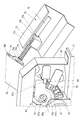
- WO2015174522A1 WO2015174522A1 PCT/JP2015/064039 JP2015064039W WO2015174522A1 WO 2015174522 A1 WO2015174522 A1 WO 2015174522A1 JP 2015064039 W JP2015064039 W JP 2015064039W WO 2015174522 A1 WO2015174522 A1 WO 2015174522A1
- Authority
- WO
- WIPO (PCT)
- Prior art keywords
- medium
- tension
- load
- winding
- applying member
- Prior art date
- Legal status (The legal status is an assumption and is not a legal conclusion. Google has not performed a legal analysis and makes no representation as to the accuracy of the status listed.)
- Ceased
Links
Images






Classifications
-
- B—PERFORMING OPERATIONS; TRANSPORTING
- B41—PRINTING; LINING MACHINES; TYPEWRITERS; STAMPS
- B41J—TYPEWRITERS; SELECTIVE PRINTING MECHANISMS, i.e. MECHANISMS PRINTING OTHERWISE THAN FROM A FORME; CORRECTION OF TYPOGRAPHICAL ERRORS
- B41J2/00—Typewriters or selective printing mechanisms characterised by the printing or marking process for which they are designed
- B41J2/005—Typewriters or selective printing mechanisms characterised by the printing or marking process for which they are designed characterised by bringing liquid or particles selectively into contact with a printing material
- B41J2/01—Ink jet
-
- B—PERFORMING OPERATIONS; TRANSPORTING
- B41—PRINTING; LINING MACHINES; TYPEWRITERS; STAMPS
- B41J—TYPEWRITERS; SELECTIVE PRINTING MECHANISMS, i.e. MECHANISMS PRINTING OTHERWISE THAN FROM A FORME; CORRECTION OF TYPOGRAPHICAL ERRORS
- B41J15/00—Devices or arrangements of selective printing mechanisms, e.g. ink-jet printers or thermal printers, specially adapted for supporting or handling copy material in continuous form, e.g. webs
- B41J15/16—Means for tensioning or winding the web
-
- B—PERFORMING OPERATIONS; TRANSPORTING
- B65—CONVEYING; PACKING; STORING; HANDLING THIN OR FILAMENTARY MATERIAL
- B65H—HANDLING THIN OR FILAMENTARY MATERIAL, e.g. SHEETS, WEBS, CABLES
- B65H23/00—Registering, tensioning, smoothing or guiding webs
- B65H23/04—Registering, tensioning, smoothing or guiding webs longitudinally
- B65H23/18—Registering, tensioning, smoothing or guiding webs longitudinally by controlling or regulating the web-advancing mechanism, e.g. mechanism acting on the running web
- B65H23/195—Registering, tensioning, smoothing or guiding webs longitudinally by controlling or regulating the web-advancing mechanism, e.g. mechanism acting on the running web in winding mechanisms or in connection with winding operations
- B65H23/198—Registering, tensioning, smoothing or guiding webs longitudinally by controlling or regulating the web-advancing mechanism, e.g. mechanism acting on the running web in winding mechanisms or in connection with winding operations motor-controlled (Controlling electrical drive motors therefor)
Definitions
- the present invention relates to a medium conveying apparatus and an ink jet printer for conveying a belt-shaped medium.
- an inkjet head that performs printing on a belt-shaped medium, a winding mechanism that winds up the medium printed by the inkjet head, and a portion of the medium that is not wound around the winding mechanism
- a device provided with a tension applying member that can apply tension to the medium by pushing it by its own weight in the rotation direction around the axis of the shaft (see, for example, Patent Document 1).
- the tension applied to the medium is too small, for example, a portion of the medium being printed by the ink jet head may be lifted, resulting in misalignment or overlap in printing on the medium, or a portion of the medium being wound by the winding mechanism may be By loosening, the medium cannot be taken up by the take-up mechanism in an orderly roll shape without gaps or slack.
- the tension applied to the medium is always stable.
- an object of the present invention is to provide a medium transport device and an ink jet printer that can stabilize the tension applied to a belt-shaped medium as compared with the conventional art.
- the medium conveying apparatus of the present invention includes a medium winding mechanism in which a belt-shaped medium is wound in a roll shape and performs at least one of feeding and winding on the medium, and the medium winding mechanism of the medium is wound around the medium winding mechanism.
- a tension applying member capable of applying tension to the medium by pushing a non-portion by its own weight in a rotation direction around a specific axis, and the tension when the tension applying member applies tension to the medium.
- the medium conveying device of the present invention does not include a load applying unit
- the tension applied to the medium by the tension applying member due to its own weight due to a change in the angle of the tension applying member around a specific axis.
- the medium conveying apparatus of the present invention includes an angle detecting unit that detects an angle of the tension applying member around the axis, and a conveying control unit that controls the medium winding mechanism, and the conveying control unit Even if the medium winding mechanism is controlled such that the angle detected by the angle detecting means is maintained within a specific range of the range in which the load applying means can apply a load to the tension applying member. good.
- the medium conveyance device of the present invention maintains the angle of the tension applying member around the specific axis within a specific range in which the load applying unit can apply a load to the tension applying member.
- the tension applied to the medium from the applying member can be more reliably stabilized.
- the load applying unit includes a compression coil spring that generates a load to be applied to the tension applying member, and a restriction member that restricts movement of the compression coil spring within a predetermined range. You may have.
- the medium conveying device of the present invention is a compression coil spring in which the means for generating the load to be applied to the tension applying member is a compression coil spring having no initial tension, so the load applied by the load applying means to the tension applying member. Can be smoothly changed according to the change of the angle of the tension applying member around the specific axis. Therefore, the medium conveying apparatus of the present invention can stabilize the tension applied to the medium as compared with the configuration in which the means for generating the load to be applied to the tension applying member is a tension coil spring having an initial tension. .
- the restricting member may restrict the expansion / contraction direction of the compression coil spring and restrict the movement range of the compression coil spring in the expansion / contraction direction.
- the medium conveying device of the present invention reliably applies the load to the tension applying member by the load applying means in the direction opposite to the rotation direction of the tension applying member by restricting the expansion / contraction direction and movement range of the compression coil spring. be able to.
- the compression coil spring is held by the regulating member, and the compression coil spring is loaded from the tension applying member when the tension applying member does not apply tension to the medium. It may be in a state where it is not applied.
- the medium conveyance device of the present invention can suppress the influence on the life of the compression coil spring due to the time during which the tension applying member does not apply tension to the medium.
- the medium winding mechanism performs both feeding and winding with respect to the medium, and the tension applying member and the load applying means are provided on the medium by the medium winding mechanism.
- the load applying means on the unwinding side is provided on the side opposite to the load applying means on the take-up side with respect to the tension applying member on the unwinding side. Then, the load applying means on the winding side may be provided on the opposite side of the tension applying member on the winding side from the load applying means on the feeding side.
- the feeding-side load applying means and the winding-side load applying means are arranged between the feeding-side tension applying member and the winding-side tension applying member.
- the feeding-side load applying means and the winding-side load applying means are arranged between the feeding-side tension applying member and the winding-side tension applying member.
- the distance between the tension applying member on the side and the tension applying member on the winding side can be shortened. Therefore, the medium carrying device of the present invention can be reduced in size.
- the medium winding mechanism performs winding of the medium
- the transport control unit is configured such that the angle detected by the angle detection unit is greater than or equal to a specific time. When it is out of range, tension may be applied to the medium by winding the medium by the medium winding mechanism.
- the medium conveying device of the present invention applies tension to the medium by winding the medium by the medium winding mechanism even when the tension applying member cannot apply tension to the medium. Can be continued.
- An ink jet printer includes the above-described medium transport device and an ink jet head that performs printing with ink on the medium to which tension is applied by the medium transport device.
- the ink jet printer of the present invention performs printing on a medium to which tension is more stabilized than before, so that the quality of printing can be improved as compared with the past.
- the medium conveying device and the ink jet printer of the present invention can stabilize the tension applied to the belt-shaped medium as compared with the related art.
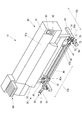
- FIG. 2 is a front view of the ink jet printer shown in FIG. 1 with a front cover removed.
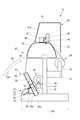
- FIG. 2 is a side cross-sectional view of the ink jet printer shown in FIG. 1 when tension is applied to a print medium by a tension applying member.
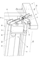
- FIG. 2 is a perspective view of a part of the medium transport device shown in FIG. 1 when observed from the front upper right side. It is a perspective view of the vicinity of the roll holder shown in FIG. 4 when observed from the front upper right side with the cover removed.
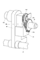
- FIG. 2 is a perspective view of a part of the medium conveyance device shown in FIG.
- (A) is a graph showing the relationship between the angle of the tension applying member shown in FIG. 3 around the axis and the load that the tension applying member applies to the print medium by its own weight when it is assumed that there is no tension adjusting device. It is.
- (B) is a graph showing the relationship between the angle of the tension applying member shown in FIG. 3 around the axis and the load applied by the compression coil spring to the tension applying member.
- (C) is a graph showing the relationship between the angle of the tension applying member shown in FIG. 3 around the axis and the load applied to the print medium by the tension applying member applied with the load from the compression coil spring.
- FIG. 8 (A) is an external appearance perspective view of the load provision means different from the load provision means shown in FIG. (B) is a side cross-sectional view of the load applying means shown in FIG. 8 (a).
- (A) is a figure which shows the load provision means different from the load provision means shown in FIG. 3 and
- FIG. (B) is a figure which shows the load provision means different from the load provision means shown to FIG.3, FIG8 and FIG.9 (a).
- FIG. 2 is a side cross-sectional view of the ink jet printer shown in FIG. 1 when a tension bar is in contact with a print medium in a state where an angle of a tension applying member centering on a specific axis exceeds an upper limit of a specific range. It is side surface sectional drawing of the inkjet printer shown in FIG. 1 in case the angle of the tension
- FIG. 1 is an external perspective view of the inkjet printer 10 according to the present embodiment when observed from the upper right side of the front.
- FIG. 2 is a front view of the inkjet printer 10 with the front cover 81a removed.
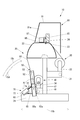
- FIG. 3 is a side cross-sectional view of the inkjet printer 10 when tension is applied to the print medium 90 by the tension applying member 50.
- an inkjet printer 10 includes a medium transport device 20 that transports a print medium 90 that is a belt-shaped medium, and a main body 80 that is installed in the medium transport device 20 and that performs printing with ink. It has.
- the medium transport device 20 includes a leg 21 installed on the floor, a platen 22 that supports a print medium 90 on which printing is performed by the main body 80, and a sub-scanning direction indicated by an arrow 10b orthogonal to the main scanning direction indicated by an arrow 10a.
- a winding mechanism 40 as a medium winding mechanism that winds up the printing medium 90 on which the printing medium 90 is wound and rolled by the main body 80, and an axis 50 a extending in the main scanning direction.
- a tension applying member 50 that is rotatable about the center and applies tension to the print medium 90, and a tension applying unit centered on the axis 50a
- An angle detecting device 60 as an angle detecting means for detecting a 50 angle theta, and a tension adjusting device 70 for adjusting the tension applied to the print medium 90 by the tensioning member 50.
- the feeding mechanism 30, the winding mechanism 40, the tension applying member 50, the angle detection device 60, and the tension adjusting device 70 are supported by the legs 21.
- the platen 22, the transport roller 23, and the pinch roller 24 extend in the main scanning direction.
- the main body 80 includes a removable front cover 81a and covers the inside of the main body 80, an operation unit 82 that is an input device such as buttons for inputting various operations, and displays various information.
- a display unit 83 which is a display device such as an LCD (Liquid Crystal Display), a plurality of ink tanks 84 for storing ink, a guide rail 85 extending in the main scanning direction indicated by an arrow 10a, and a main scanning direction
- a carriage 86 that is movably supported by the guide rail 85 and a plurality of inkjet heads 87 that are mounted on the carriage 86 and eject ink toward the print medium 90 are provided.
- the feeding mechanism 30 includes a rail 31 that extends in the main scanning direction indicated by an arrow 10 a and is supported by the legs 21, and a print medium 90 before printing by the inkjet head 87.
- a roll holder 32 and a roll holder 33 are provided to rotatably support the paper tube by sandwiching a wound paper tube (not shown) from both sides.
- the rail 31 supports the roll holder 32 and the roll holder 33 so as to be movable in the main scanning direction. That is, the distance between the roll holder 32 and the roll holder 33 in the main scanning direction can be changed in accordance with the width of the print medium 90 to be used.
- the roll holder 32 includes a rotating shaft 32a that is inserted into a hole at the end of the paper tube.
- the roll holder 33 includes a rotating shaft 33a that is inserted into the hole at the end of the paper tube.
- the rotation shaft 32a and the rotation shaft 33a are rotatable around a central axis extending in the main scanning direction.
- the take-up mechanism 40 includes a rail 41 that extends in the main scanning direction indicated by an arrow 10 a and is supported by the legs 21, and a print medium 90 that has been printed by the inkjet head 87.
- a rail 41 that extends in the main scanning direction indicated by an arrow 10 a and is supported by the legs 21, and a print medium 90 that has been printed by the inkjet head 87.
- a roll holder 42 and a roll holder 43 that rotatably support the paper tube by sandwiching a paper tube (not shown) for winding the paper tube from both sides.
- the rail 41 supports the roll holder 42 and the roll holder 43 so as to be movable in the main scanning direction. That is, the distance between the roll holder 42 and the roll holder 43 in the main scanning direction can be changed in accordance with the width of the print medium 90 to be used.
- the roll holder 42 includes a rotation shaft 42a that is inserted into a hole at the end of the paper tube.
- the roll holder 43 includes a rotating shaft 43a that is inserted into the hole at the end of the paper tube.
- the rotation shaft 42a and the rotation shaft 43a can rotate around a central axis extending in the main scanning direction.
- FIG. 4 is a perspective view of a part of the medium transport device 20 when observed from the upper right side of the front.
- FIG. 5 is a perspective view of the vicinity of the roll holder 43 when observed from the upper right side of the front face with the cover 47 removed.
- the winding mechanism 40 includes a motor 44 that generates a driving force for rotating the rotating shaft 43 a of the roll holder 43, and a driving force transmission mechanism from the motor 44 to the rotating shaft 43 a. And a cover 47 that covers the motor 44 and the torque limiter 45.
- the torque limiter 45 is configured to cut off the connection when an overload is applied.
- the take-up mechanism 40 In order to transmit the power of the motor 44 to the paper tube around which the print medium 90 is wound, the take-up mechanism 40 includes a gear support shaft 44a included in the motor 44 and a first gear 44b engaged with the gear support shaft 44a. And the second gear 44c having a diameter smaller than that of the first gear 44b and the second gear 44c, and the print medium 90 is wound. It has a third gear 44d that rotates on the same rotation axis as the rotation axis of the paper tube.
- the torque limiter 45 restricts the torque generated between the first gear 44b and the second gear 44c, and when the torque of a specific magnitude occurs, the rotation of the first gear 44b is controlled to the second gear 44c. It works so as not to tell.
- the torque limiter 45 interrupts transmission of power from the motor 44 side to the print medium 90 side when an excessive torque is generated between the motor 44 side and the print medium 90 side.
- the torque limiter 45 can be adjusted in torque to cut off transmission of power from the motor 44 side to the print medium 90 side.
- the tension applying member 50 extends on the axis 50a and the arm 51 supported on the leg 21 so as to be rotatable about a shaft 51a extending on the axis 50a.
- the arm 52 is supported by the leg 21 so as to be rotatable about a shaft 52a, and the tension bar 53 extends in the main scanning direction and contacts the print medium 90.
- the tension bar 53 is supported by the arm 51 and the arm 52.
- the tension applying member 50 can apply tension to the printing medium 90 by pushing a portion of the printing medium 90 that is not wound around the winding mechanism 40 by its own weight in the rotation direction indicated by the arrow 10c about the axis 50a. It is.
- FIG. 6 is a perspective view of a part of the medium transport device 20 when observed from the upper left side of the front in a state in which the internal configuration of the angle detection device 60 is shown.
- the angle detection device 60 is fixed to the leg 61 and the plate 61 fixed to the shaft 52 a of the arm 52 (not shown in FIG. 6, see FIG. 2).
- the plate 61 is arranged side by side in the hole 61a into which the shaft 52a is inserted and in the direction indicated by the arrow 10c (the direction indicated by the arrow 10c is the same direction in FIGS. 3 and 6).
- a plurality of slits 61b for detection by the photo interrupter 62 and the photo interrupter 63 are formed.
- the plate 61 includes a detected portion 61 c for detection by the photo interrupter 64. That is, the angle detection device 60 is an encoder that detects an angle ⁇ (see FIG. 3).
- the tension adjusting device 70 includes a compression coil spring 71 that generates a load to be applied to the tension applying member 50, and a flange 72 a near one end, and is inserted into the compression coil spring 71.
- the arm side fixing member 74 is fixed and one end of the bar 72 is fixedly connected.
- the leg-side fixing member 73 has a hole 73a into which the bar 72 is inserted, and includes a bar support member 73b that supports the bar 72 so as to be movable in the hole 73a.
- the tension adjusting device 70 constitutes load applying means for applying a load to the tension applying member 50.
- the bar 72 and the leg-side fixing member 73 constitute a regulating member that regulates the movement of the compression coil spring 71 within a predetermined range.
- the compression coil spring 71 is in contact with the flange 72a of the bar 72 and the other end is fixed to the leg side. It is in contact with the bar support member 73b of the member 73.
- the bar 72 regulates the expansion / contraction direction of the compression coil spring 71. Further, the bar 72 and the leg-side fixing member 73 restrict the movement range of the compression coil spring 71 in the expansion / contraction direction of the compression coil spring 71.
- the leg-side fixing member 73 includes a bar support member 73b in which a hole 73a is formed, and a side wall connection member 73c fixedly connected to the side wall 65 of the angle detection device 60.
- the bar support member 73b is supported by the side wall connection member 73c so as to be rotatable about an axis parallel to the axis 50a.
- the arm-side fixing member 74 includes a bar connection member 74 a to which one end of the bar 72 is fixedly connected, and an arm connection member 74 b that is fixedly connected to the arm 52.
- the bar connecting member 74a is supported by the arm connecting member 74b so as to be rotatable about an axis parallel to the axis 50a.
- FIG. 7A shows an angle ⁇ (see FIG. 3) of the tension applying member 50 around the axis 50a, and the print medium 90 due to its own weight when the tension adjusting device 70 is assumed to be absent. It is a graph which shows the relationship with the load provided to.
- FIG. 7B is a graph showing the relationship between the angle ⁇ and the load applied to the tension applying member 50 by the compression coil spring 71.
- FIG. 7C is a graph showing the relationship between the angle ⁇ and the load applied to the print medium 90 by the tension applying member 50 applied with the load from the compression coil spring 71.
- the load is in the direction indicated by the arrow 10c (see FIG. 3) that rotates about the axis 50a by its own weight.
- the load is a positive load.
- the compression coil spring 71 applies a load to the tension applying member 50 in the direction indicated by the arrow 10d (see FIG. 3) opposite to the direction indicated by the arrow 10c. Is supposed to be granted.
- the magnitude of the load applied by the compression coil spring 71 to the tension applying member 50 is such that the angle ⁇ at which the tension applied by the tension applying member 50 to the print medium 90 by its own weight is large. In other words, the smaller the value of the angle ⁇ in FIG. Accordingly, the load applied to the print medium 90 by the tension applying member 50 to which the load is applied from the compression coil spring 71 is substantially constant regardless of the angle ⁇ as shown in FIG. That is, the tension applied to the print medium 90 by the tension applying member 50 to which a load is applied from the compression coil spring 71 is substantially constant regardless of the angle ⁇ .
- the tension applying member 50 is configured such that the angle ⁇ does not become smaller than 52 °, for example, by the action of a stopper (not shown).
- the range in which the compression coil spring 71 can apply a load to the tension applying member 50 is, for example, a range in which the angle ⁇ is 52 ° to 70 °. Further, as will be described later, the tension applying member 50 has a specific range (for example, 62. 2) out of a range in which the compression coil spring 71 can apply a load to the tension applying member 50 by winding the print medium 90 by the winding mechanism 40.
- the angle ⁇ is maintained within a range of 5 ° to 70 °.
- the compression coil spring 71 as a part of the load applying means for applying a load to the tension applying member 50 has one end in contact with the flange 72 a of the bar 72 and the other end in contact with the leg-side fixing member 73.
- the present invention is not limited to this.
- FIG. 8 (a) is an external perspective view of a load applying means different from the load applying means shown in FIG.
- FIG. 8B is a side cross-sectional view of the load applying means shown in FIG.
- the load applying means shown in FIG. 8 shows a compression coil spring 71, a columnar member 77 formed with a columnar groove 77a, and a columnar member 78 formed with an annular groove 78a.
- the leg-side fixing member 73 is not included.
- the member 77 includes an end portion 77b fixedly connected to the arm-side fixing member 74 and a side wall 77c that forms a groove 77a together with the end portion 77b, similarly to one end of the bar 72 shown in FIG. At least a part of the side wall 77 c of the member 77 is inserted into the groove 78 a of the member 78.
- the member 77 houses the compression coil spring 71 in the groove 77a.
- a part of the side wall 77c of the member 77 may be opened so that at least a part of the compression coil spring 71 can be seen from the outside.
- the side wall 77c may have a mesh shape.
- the member 78 includes an end portion 78b, a columnar core 78c connected to the end portion 78b, and a side wall 78d that forms a groove 78a together with the end portion 78b and the core 78c. At least a part of the core 78 c of the member 78 is inserted into the groove 77 a of the member 77.
- a side wall 78 d of the member 78 is fixed to the leg-side fixing member 73. A part of the side wall 78d of the member 78 may be open like the side wall 77c of the member 77.
- the compression coil spring 71 shown in FIG. 8 is in contact with the end 77 b of the member 77 and the other end is the core 78 c of the member 78. Touching.
- the member 77 and the member 78 constitute a restricting member that restricts the movement of the compression coil spring 71 within a predetermined range.
- the member 77 restricts the expansion / contraction direction of the compression coil spring 71. Further, the member 77 and the member 78 restrict the movement range of the compression coil spring 71 in the expansion / contraction direction of the compression coil spring 71.
- FIG. 9A is a view showing a load applying means different from the load applying means shown in FIGS.
- FIG. 9B is a diagram showing a load applying means different from the load applying means shown in FIGS. 3, 8 and 9A.
- a compression coil spring as a part of a load applying means is formed on an arc 52a vertically below the center axis, with a shaft 52a extending on the axis 50a as the center axis.
- 75 may be provided, and one end may be locked to a part of the angle detection device 60 and the other end may be locked to the arm 52.
- a guide groove formed in an arc shape may be provided, and the compression coil spring 75 may be disposed in the guide groove.
- the restoring force causes the tension in the direction indicated by the arrow 10d which is opposite to the rotation direction indicated by the arrow 10c of the tension applying member 50.
- a load can be applied to the applying member 50.
- the tension coil spring 76 when used as a part of the load applying means instead of the compression coil spring, as shown in FIG. 9 (b), the axis 52a extending on the axis 50a is used as the central axis, and the center
- the tension coil spring 76 may be disposed on the arc on the upper side in the vertical direction of the shaft, and one end may be locked to a part of the angle detection device 60 and the other end may be locked to the arm 52.
- a guide groove formed in an arc shape may be provided, and the tension coil spring 76 may be disposed in the guide groove.
- the tension force causes the tension in the direction indicated by the arrow 10d that is opposite to the rotation direction indicated by the arrow 10c of the tension applying member 50.
- a load can be applied to the applying member 50.
- the tension adjusting device 70 can be made compact.
- the coil spring is locked to the arm 52 by hooking the coil spring to the arm 52 by providing a hook portion at the tip of the coil spring, stress concentration easily occurs in the hook portion of the coil spring. There is a risk of impact. Therefore, from the viewpoint of long-term use and maintenance, as shown in FIG. 3, it is preferable that the bar 72 is inserted into the compression coil spring 71 as the load applying means.
- FIG. 10 is a side cross-sectional view of the inkjet printer 10 when the tension applying member 50 is in the retracted position.
- the tension applying member 50 is configured such that the angle ⁇ does not become larger than 95 °, for example, by the action of a stopper (not shown).
- the position of the tension applying member 50 shown in FIG. When the tension applying member 50 exists at the retracted position, the tension applying member 50 cannot contact the print medium 90 and therefore cannot apply tension to the print medium 90.
- FIG. 11 is a block diagram of the ink jet printer 10.
- the inkjet printer 10 includes the operation unit 82 and the display unit 83 described above, a communication unit 11 that is a communication device that communicates with an external device such as a PC (Personal Computer), and the inkjet head described above.
- EEPROM Electrically Erasable Program
- the ble Read Only Memory) storing unit 16 is a storage device such as, and a control unit 17 that controls the entire inkjet printer 10.
- the length of the print medium 90 conveyed by the conveyance roller 23 is the same as the cumulative length in the circumferential direction of the point in contact with the print medium 90 in the conveyance roller 23, the diameter of the conveyance roller 23, It can be calculated based on the detection value of the encoder 14. Specifically, when the length of the printing medium 90 conveyed by the conveyance roller 23 is L1, the diameter of the conveyance roller 23 is R1, and the rotation angle obtained from the detection value of the encoder 14 is ⁇ 1 [rad], L1 Is “ ⁇ 1 ⁇ R1”.
- the control unit 17 includes, for example, a CPU (Central Processing Unit), a ROM (Read Only Memory) that stores programs and various data in advance, and a RAM (Random Access Memory) used as a work area of the CPU. ing.
- the CPU executes a program stored in the ROM or the storage unit 16.
- the control unit 17 functions as a conveyance control unit 17 a that controls conveyance of the print medium 90 by executing a program stored in the ROM or the storage unit 16.
- the control unit 17 of the ink jet printer 10 receives print data transmitted from the outside via the communication unit 11, the ink jet head 87, the carriage drive device 12, the transport roller drive device 13, and the take-up device based on the print data.
- the mechanism 40 printing by the inkjet head 87 is executed.
- control unit 17 controls the carriage driving device 12 to move the carriage 86 along the guide rail 85 in the main scanning direction indicated by the arrow 10 a, so that the inkjet head 87 mounted on the carriage 86. Is moved relative to the print medium 90 in the main scanning direction. At this time, the control unit 17 performs printing in the main scanning direction by ejecting ink droplets toward the print medium 90 by the inkjet head 87.
- the control unit 17 is sandwiched between the transport roller 23 and the pinch roller 24 by controlling the transport roller driving device 13 and rotating the transport roller 23 every time printing in the main scanning direction is completed.
- the print medium 90 is moved in the sub-scanning direction indicated by the arrow 10b.
- control unit 17 moves the inkjet head 87 and the print medium 90 relative to each other in the sub-scanning direction, thereby changing the print position of the inkjet head 87 on the print medium 90 in the sub-scanning direction. Then, the control unit 17 executes printing in the main scanning direction again at a new printing position in the sub scanning direction.
- the print medium 90 when the print medium 90 is transported by the transport roller 23, the print medium 90 wound around the paper tube rotatably supported by the roll holder 32 and the roll holder 33 of the feed mechanism 30 is removed from the feed mechanism 30. It is paid out.
- the print medium 90 When the print medium 90 is transported by the transport roller 23, the print medium 90 after printing by the ink jet head 87 is applied with tension by at least one of the winding mechanism 40 and the tension applying member 50, and the winding mechanism. 40 is wound up.
- FIG. 12 is a flowchart of the operation of the transport control means 17a.
- the conveyance control means 17a executes the operation shown in FIG. 12 when printing is started.
- the conveyance control unit 17a determines the current tension application mode for applying tension to the print medium 90 (S101).
- the tension applying mode includes a “bar mode” in which tension is applied to the print medium 90 by the tension applying member 50 and a “winding mode” in which tension is applied to the print medium 90 by the winding mechanism 40.
- the control unit 17 can accept designation of either “bar mode” or “winding mode” via the operation unit 82.
- the control unit 17 can accept the designation of “bar mode” only when the angle ⁇ detected by the angle detection device 60 exceeds a specific angle, for example, 55 °.
- the specific angle is an angle smaller than the lower limit of the specific range described above and detected by the photo interrupter 64.
- conveyance control means 17a determines in S101 that the current tension application mode is the “bar mode”, it executes a bar mode process that is a “bar mode” process (S102).
- the transport control means 17a operates as follows.
- the conveyance control means 17a determines whether or not the angle ⁇ detected by the angle detection device 60 is within a specific range.
- whether or not the angle ⁇ is within a specific range can be determined by detection values from the photo interrupter 62 and the photo interrupter 63.
- the conveyance control means 17a determines that the angle ⁇ is within a specific range, it determines the current tension application mode. When determining that the current tension applying mode is the “winding mode”, the transport control unit 17a turns off the flag and ends the bar mode processing. When it is determined that the current tension application mode is “bar mode”, the transport control unit 17a continuously executes the bar mode process when printing is not finished, and when printing is finished, A flag is set and the bar mode process is terminated.
- the conveyance control unit 17a determines that the angle ⁇ is not within a specific range, the winding mechanism 40 generates power for winding the print medium 90 by the winding mechanism 40, whereby the operation of the winding mechanism 40 is performed. To start. At this time, the conveyance control unit 17a continues the operation of the winding mechanism 40 for a specific time from the start, for example, for 10 seconds. The specific time is based on the value of the clock 15.
- FIG. 14 is a side cross-sectional view of the inkjet printer 10 when the angle ⁇ of the tension applying member 50 around the axis 50a is below the lower limit of a specific range.
- the print medium 90 is wound by the winding mechanism 40 for a specific time.
- the angle ⁇ is set within a specific range. Therefore, the reason why the operation of the winding mechanism 40 is continued for a specific time is to make the angle ⁇ within a specific range when the angle ⁇ is below the lower limit of the specific range.
- the transport control unit 17a determines that the angle ⁇ is not within the specific range after the elapse of a specific time, the transport control unit 17a defeats the flag and ends the bar mode process.
- the conveyance control unit 17 a determines in S ⁇ b> 101 that the current tension application mode is “winding mode”, the conveyance control unit 17 a performs winding mode processing that is processing of “winding mode” (S ⁇ b> 103). ).
- the conveyance control unit 17 a starts the operation of the winding mechanism 40 by causing the motor 44 to generate power for winding the print medium 90 by the winding mechanism 40.
- the conveyance control means 17a determines the current tension applying mode.
- the conveyance control unit 17a continues the winding process. If the conveyance control unit 17a determines that the printing is completed, the conveyance control unit 17a sets the flag and then operates the winding mechanism 40 To complete the winding mode process.
- the transport control means 17a determines whether or not a flag is set (S104).
- conveyance control means 17a determines in S104 that the flag has fallen, it executes a winding mode process (S103).
- transport control means 17a determines in S105 that the flag has fallen, it executes the bar mode process (S102).
- the conveyance control unit 17a controls the winding mechanism 40 so that the angle ⁇ is maintained within a specific range. That is, the conveyance control unit 17a stops winding by the winding mechanism 40 when the angle ⁇ is within a specific range, and by the winding mechanism 40 when the angle ⁇ is not within the specific range. Perform winding. Therefore, when the angle ⁇ is within a specific range, the print medium 90 is wound from the transport roller 23 by the amount transported by the transport roller 23 in a state where the tension is applied by the tension applying member 50. The length up to 40 becomes longer. As a result, the angle ⁇ gradually decreases and falls below the lower limit of the specific range and is not within the specific range.
- the tension is applied by the tension applying member 50.
- the length from the conveyance roller 23 to the winding mechanism 40 is shortened by the amount wound by the winding mechanism 40.
- the angle ⁇ gradually increases and falls within a specific range.
- the print medium 90 is wound up by the winding mechanism 40 in a state where the tension is applied by the tension applying member 50.
- winding diameter the diameter of a roll-shaped printing medium 90 wound around a paper tube rotatably supported by the winding mechanism 40
- winding diameter the diameter of a roll-shaped printing medium 90 wound around a paper tube rotatably supported by the winding mechanism 40
- the angle ⁇ may not increase even if the winding mechanism 40 is controlled so as to wind up the print medium 90 (winding). There is a possibility that the take-up mechanism 40 cannot be wound). Actually, when the winding diameter is increased, the roll-shaped print medium 90 is heavier. Therefore, even when the angle ⁇ is within a specific range, the winding mechanism is configured to wind the print medium 90. Even if 40 is controlled, the possibility that the angle ⁇ does not increase (the possibility that the winding mechanism 40 cannot be wound) is further increased.
- the transport control unit 17a takes up the winding mechanism 40 so that the winding mechanism 40 winds up the print medium 90 by a winding mode process after a specific time has passed in a state where the angle ⁇ is not within the specific range. To control. Accordingly, the printing medium 90 is wound up by the winding mechanism 40 by the amount conveyed by the conveying roller 23 in a state where the tension is applied by the winding mechanism 40 whose torque is limited by the torque limiter 45.
- the conveyance control means 17a changes the position of the tension applying member 50 to the retracted position shown in FIG. 10 by, for example, manually moving the tension applying member 50 by the user of the ink jet printer 10 during the bar mode process.
- the angle ⁇ exceeds the upper limit of the specific range and is not within the specific range, and the tension bar 53 does not come into contact with the print medium 90
- printing is performed on the winding mechanism 40 by the winding mode process.
- the winding mechanism 40 is controlled so that the medium 90 is wound. Accordingly, the printing medium 90 is wound up by the winding mechanism 40 by the amount conveyed by the conveying roller 23 in a state where the tension is applied by the winding mechanism 40 whose torque is limited by the torque limiter 45.
- the user can shift to the winding mode process by designating the “winding mode” via the operation unit 82 when the bar mode process is being executed.
- the user can shift to the bar mode process by designating the “bar mode” via the operation unit 82 when the winding mode process is being executed.
- the tension applying member 50 when the mode is changed from the winding mode process to the bar mode process, when the tension applying member 50 is in the retracted position as shown in FIG. 10, the angle ⁇ is not in a specific range. Therefore, the bar mode process returns to the winding mode process as described above. Therefore, when the user shifts from the winding mode process to the bar mode process and the tension applying member 50 is in the retracted position, the tension applying member 50 contacts the print medium 90 as shown in FIG. It is preferable to manually move the tension applying member 50 to a position where the tension is applied.
- the ink jet printer 10 has the tension applied to the print medium 90 by the tension applying member 50 due to its own weight due to a change in the angle ⁇ when it is assumed that the compression coil spring 71 is not provided. Since the compression coil spring 71 absorbs at least a part of the increase of the angle ⁇ according to the variation of the angle ⁇ , the tension applied from the tension applying member 50 to the printing medium 90 is more stabilized than the conventional against the variation of the angle ⁇ . can do. Therefore, the ink jet printer 10 can improve the quality of printing compared to the prior art by executing printing on the printing medium 90 to which tension is more stabilized than before.
- the inkjet printer 10 maintains the angle ⁇ within a specific range in which the compression coil spring 71 can apply a load to the tension applying member 50, so that the tension applied from the tension applying member 50 to the print medium 90 can be further ensured. Can be stabilized.
- the angle ⁇ may not be maintained within a specific range even when the winding mechanism 40 winds up the print medium 90 due to a cause such as a large winding diameter.
- the tension applying member 50 cannot apply tension to the print medium 90.
- the inkjet printer 10 applies tension to the print medium 90 by winding the print medium 90 by the winding mechanism 40 even when the tension applying member 50 cannot apply tension to the print medium 90.
- the application of tension to the print medium 90 can be continued. Therefore, the inkjet printer 10 can continue printing on the print medium 90 even when the tension applying member 50 cannot apply tension to the print medium 90 due to its own weight.
- the inkjet printer 10 since the means for generating a load to be applied to the tension applying member 50 is the compression coil spring 71 having no initial tension, the load applied by the load applying means to the tension applying member 50 is expressed by an angle ⁇ . It can be made to change smoothly according to the change of. Therefore, the inkjet printer 10 can stabilize the tension applied to the print medium 90 as compared with a configuration in which the means for generating a load to be applied to the tension applying member is a tension coil spring having an initial tension.
- the ink jet printer 10 does not regulate the expansion / contraction direction and the movement range of the compression coil spring 71, for example, the compression coil spring 71 is compressed in a bent state, and the tension is applied by the load application unit. There is a possibility that a desired urging force for applying a load to the member 50 cannot be exhibited by the compression coil spring 71.
- the load application unit reliably applies a load to the tension application member 50 in the direction opposite to the rotation direction of the tension application member 50. Can be granted.
- the load applying means may be configured using a spring other than the compression coil spring, such as a tension coil spring.
- the inkjet printer 10 can stabilize the tension applied to the print medium 90 with a simple configuration when the load applying means is configured using a spring.
- the load applying means may be configured not to use a spring as long as the tension applied to the print medium 90 by the tension applying member 50 can be adjusted.
- the inkjet printer 10 includes the angle detection devices 60 at both ends in the main scanning direction indicated by the arrow 10a as shown in FIG. 2, but the tension adjusting device 70 also has both ends in the main scanning direction as shown in FIG. You may be prepared for.
- the load applied to the tension applying member 50 by the tension adjusting device 70 can be aligned at both ends in the main scanning direction.
- the tension applied to the print medium 90 by 50 can be made uniform in the main scanning direction, which is preferable.
- the load of the tension applying member 50 is applied to the load applying means of the tension adjusting device 70 from the upper side in the vertical direction as shown in FIG.
- the inkjet printer 10 may be configured such that the load of the tension applying member 50 is applied to the load applying means of the tension adjusting device 70 from the lower side in the vertical direction as shown in FIG.
- the load applying means is provided at a point-symmetrical position about the axis 50 a as compared with the configuration shown in FIG. 3.
- the inkjet printer 10 includes, for example, a side wall 65 of the angle detection device 60 that extends toward the feeding mechanism 30, and a load applying unit is fixed to the extended side wall 65. Just do it.
- the inkjet printer 10 uses the winding mechanism 40 as the medium winding mechanism of the present invention.
- the feeding mechanism 30 is not used as the medium winding mechanism of the present invention, and the feeding mechanism 30 is used as the medium winding mechanism of the present invention.
- the feeding mechanism 30 may be the medium winding mechanism of the present invention while the winding mechanism 40 is the medium winding mechanism of the present invention.
- the inkjet printer 10 is configured to rotate at least one of the rotating shaft 32a of the roll holder 32 of the feeding mechanism 30 and the rotating shaft 33a of the roll holder 33.
- the feeding mechanism 30 includes a motor that generates a driving force, and has the same configuration as the tension applying member 50, the angle detection device 60, and the tension adjusting device 70 on the feeding side.
- the feeding mechanism 30 is configured so that the feeding amount of the printing medium 90 by the feeding mechanism 30 is smaller than the feeding amount of the printing medium 90 by the feeding roller 23. By controlling this motor, it is possible to increase the tension applied to the print medium 90 from the feeding mechanism 30 to the transport roller 23.
- the inkjet printer 10 controls the motor of the feeding mechanism 30 so that the feeding amount of the printing medium 90 by the feeding mechanism 30 is larger than the feeding amount of the printing medium 90 by the feeding roller 23, so The tension applied to the print medium 90 can be weakened.
- the inkjet printer 10 performs textile printing (direct printing onto the printing medium 90 when the printing medium 90 is a cloth). Such as printing), which is preferable for printing that needs to be fed out with tension applied to the printing medium 90 itself.
- the tension adjusting device 70 is placed at the position shown in FIG. The tension adjusting device and the tension adjusting device on the take-up side are mutually buffered. Therefore, as shown in FIG.
- the feeding-side load applying means is provided on the side opposite to the winding-side load applying means with respect to the feeding-side tension applying member, and the winding-side load applying means is provided.
- the means is preferably provided on the opposite side of the take-up-side load applying means with respect to the take-up-side tension applying member.
- the feeding-side load applying means and the winding-side load applying means are not arranged between the feeding-side tension applying member and the winding-side tension applying member.
- the feeding-side load applying means and the winding-side load applying means are arranged between the feeding-side tension applying member and the winding-side tension applying member, the feeding-side tension The distance between the applying member and the tension applying member on the winding side can be shortened. Therefore, the inkjet printer 10 shown in FIG. 18 can be miniaturized.
- the inkjet printer 10 is configured to relatively move the inkjet head 87 and the print medium 90 in the sub-scanning direction by conveying the print medium 90 in the sub-scanning direction indicated by the arrow 10b.
- a configuration other than the configuration may be used.
- the inkjet printer 10 may have a configuration in which the inkjet head 87 and the print medium 90 are relatively moved in the sub-scanning direction by moving the inkjet head 87 in the sub-scanning direction.
Landscapes
- Handling Of Continuous Sheets Of Paper (AREA)
- Registering, Tensioning, Guiding Webs, And Rollers Therefor (AREA)
- Controlling Rewinding, Feeding, Winding, Or Abnormalities Of Webs (AREA)
- Ink Jet (AREA)
Abstract
帯状の媒体に付与する張力を従来より安定化することができる媒体搬送装置およびインクジェットプリンターを提供する。 媒体搬送装置(20)は、印刷媒体(90)に対して巻き取りを実行する巻き取り機構(40)と、印刷媒体(90)のうち巻き取り機構(40)に巻き付けられていない部分を軸線(50a)を中心とした矢印(10c)で示す回転方向に自重によって押すことによって印刷媒体(90)に張力を付与可能である張力付与部材(50)と、矢印(10c)で示す回転方向とは反対方向である矢印(10d)で示す方向に張力付与部材(50)に荷重を付与する圧縮コイルバネ(71)とを備えており、圧縮コイルバネ(71)は、軸線(50a)を中心とした張力付与部材(50)の角度θが、張力付与部材(50)が自重によって印刷媒体(90)に付与する張力が大きい角度であるほど、大きい荷重を張力付与部材(50)に付与する。
Description
本発明は、帯状の媒体を搬送する媒体搬送装置およびインクジェットプリンターに関する。
従来の媒体搬送装置として、帯状の媒体に印刷を実行するインクジェットヘッドと、インクジェットヘッドによって印刷が実行された媒体を巻き取る巻き取り機構と、媒体のうち巻き取り機構に巻き付けられていない部分を特定の軸線を中心とした回転方向に自重によって押すことによって媒体に張力を付与可能である張力付与部材とを備えているものが知られている(例えば、特許文献1参照。)。
媒体に付与する張力が小さ過ぎると、例えば、媒体のうちインクジェットヘッドによる印刷中の部分が浮くことによって媒体における印刷にズレや重なりが生じたり、媒体のうち巻き取り機構による巻き取り中の部分が緩むことによって媒体が隙間や弛みなく整然とロール状に巻き取り機構によって巻き取られることができなくなったりする。また、媒体に付与する張力が大き過ぎると、例えば、媒体が伸びたり裂けたりする。したがって、媒体に付与する張力は、常に安定していることが好ましい。
しかしながら、従来の媒体搬送装置においては、軸線を中心とした張力付与部材の角度の変動によって、張力付与部材に働く重力のうち軸線を中心とした張力付与部材の回転方向の分力の大きさが変動するので、張力付与部材が自重によって媒体に付与する張力が変動するという問題がある。
そこで、本発明は、帯状の媒体に付与する張力を従来より安定化することができる媒体搬送装置およびインクジェットプリンターを提供することを目的とする。
本発明の媒体搬送装置は、帯状の媒体がロール状に巻き付けられて前記媒体に対して繰り出しおよび巻き取りの少なくとも一方を実行する媒体巻き付け機構と、前記媒体のうち前記媒体巻き付け機構に巻き付けられていない部分を特定の軸線を中心とした回転方向に自重によって押すことによって前記媒体に張力を付与可能である張力付与部材と、前記張力付与部材が前記媒体に張力を付与している場合の前記張力付与部材の自重による前記軸線を中心とした回転方向とは反対方向に前記張力付与部材に荷重を付与する荷重付与手段とを備えており、前記荷重付与手段は、前記軸線を中心とした前記張力付与部材の角度が、前記張力付与部材が自重によって前記媒体に付与する張力が大きい角度であるほど、大きい荷重を前記張力付与部材に付与することを特徴とする。
この構成により、本発明の媒体搬送装置は、荷重付与手段を備えていないと仮定した場合に特定の軸線を中心とした張力付与部材の角度の変動によって張力付与部材が自重によって媒体に付与する張力が大きくなる分の少なくとも一部を、特定の軸線を中心とした張力付与部材の角度の変動に応じて荷重付与手段によって吸収するので、特定の軸線を中心とした張力付与部材の角度の変動に対して、張力付与部材から帯状の媒体に付与する張力を従来より安定化することができる。
また、本発明の媒体搬送装置は、前記軸線を中心とした前記張力付与部材の角度を検出する角度検出手段と、前記媒体巻き付け機構を制御する搬送制御手段とを備えており、前記搬送制御手段は、前記角度検出手段によって検出された角度が、前記荷重付与手段が前記張力付与部材に荷重を付与可能な範囲のうち特定の範囲内に維持されるように前記媒体巻き付け機構を制御しても良い。
この構成により、本発明の媒体搬送装置は、特定の軸線を中心とした張力付与部材の角度を、荷重付与手段が張力付与部材に荷重を付与可能である特定の範囲内に維持するので、張力付与部材から媒体に付与する張力を更に確実に安定化することができる。
また、本発明の媒体搬送装置において、前記荷重付与手段は、前記張力付与部材に付与するための荷重を生成する圧縮コイルバネと、前記圧縮コイルバネの移動を所定の範囲内に規制する規制部材とを有しても良い。
この構成により、本発明の媒体搬送装置は、張力付与部材に付与するための荷重を生成する手段が初張力を有していない圧縮コイルバネであるので、荷重付与手段が張力付与部材に付与する荷重を、特定の軸線を中心とした張力付与部材の角度の変動に応じて、滑らかに変動させることができる。したがって、本発明の媒体搬送装置は、張力付与部材に付与するための荷重を生成する手段が初張力を有する引張コイルバネである構成と比較して、媒体に付与する張力を安定化することができる。
また、本発明の媒体搬送装置において、前記規制部材は、前記圧縮コイルバネの伸縮方向を規制し、かつ、前記伸縮方向における前記圧縮コイルバネの移動範囲を規制するものであっても良い。
この構成により、本発明の媒体搬送装置は、圧縮コイルバネの伸縮方向および移動範囲を規制することで、張力付与部材の回転方向と逆方向に確実に荷重付与手段によって張力付与部材に荷重を付与することができる。
また、本発明の媒体搬送装置において、前記圧縮コイルバネは、前記規制部材によって保持されており、前記圧縮コイルバネは、前記張力付与部材が前記媒体に張力を付与しない場合において、前記張力付与部材から荷重がかかっていない状態となっても良い。
この構成により、本発明の媒体搬送装置は、張力付与部材が媒体に張力を付与しない時間による圧縮コイルバネの寿命への影響を抑制することができる。
また、本発明の媒体搬送装置において、前記媒体巻き付け機構は、前記媒体に対して繰り出しおよび巻きとりの両方を実行し、前記張力付与部材および前記荷重付与手段は、前記媒体巻き付け機構による前記媒体の繰り出し側および巻き取り側の両方に設けられていて、繰り出し側の前記荷重付与手段は、繰り出し側の前記張力付与部材に対して、巻き取り側の前記荷重付与手段とは反対側に設けられていて、巻き取り側の前記荷重付与手段は、巻き取り側の前記張力付与部材に対して、繰り出し側の前記荷重付与手段とは反対側に設けられていても良い。
この構成により、本発明の媒体搬送装置は、繰り出し側の張力付与部材と、巻き取り側の張力付与部材との間に繰り出し側の荷重付与手段と、巻き取り側の荷重付与手段とが配置されていないので、繰り出し側の張力付与部材と、巻き取り側の張力付与部材との間に繰り出し側の荷重付与手段と、巻き取り側の荷重付与手段とが配置される構成と比較して、繰り出し側の張力付与部材と、巻き取り側の張力付与部材との間の距離を短縮することができる。したがって、本発明の媒体搬送装置は、小型化することができる。
また、本発明の媒体搬送装置において、前記媒体巻き付け機構は、前記媒体に対して巻き取りを実行し、前記搬送制御手段は、前記角度検出手段によって検出された角度が特定の時間以上前記特定の範囲外である場合に、前記媒体巻き付け機構による前記媒体の巻き取りによって前記媒体に張力を付与しても良い。
媒体巻き付け機構に巻き付けられているロール状の媒体の径が大きいなどの原因によって、媒体巻き付け機構が媒体を巻き取ったとしても、特定の軸線を中心とした張力付与部材の角度を特定の範囲内に維持することができなくなる場合がある。このような場合には、張力付与部材は、媒体に張力を付与することができなくなる。しかしながら、本発明の媒体搬送装置は、張力付与部材が媒体に張力を付与することができない場合であっても、媒体巻き付け機構による媒体の巻き取りによって媒体に張力を付与するので、媒体への張力の付与を継続することができる。
本発明のインクジェットプリンターは、上述の媒体搬送装置と、前記媒体搬送装置によって張力が付与されている前記媒体に対してインクによる印刷を実行するインクジェットヘッドとを備えていることを特徴とする。
この構成により、本発明のインクジェットプリンターは、従来より安定化された張力が付与されている媒体に対して印刷を実行するので、印刷の品質を従来より向上することができる。
本発明の媒体搬送装置およびインクジェットプリンターは、帯状の媒体に付与する張力を従来より安定化することができる。
以下、本発明の実施の形態について、図面を用いて説明する。
まず、本実施の形態に係るインクジェットプリンターの構成について説明する。
図1は、正面右上側から観察された場合の本実施の形態に係るインクジェットプリンター10の外観斜視図である。図2は、フロントカバー81aが取り外された状態でのインクジェットプリンター10の正面図である。図3は、張力付与部材50によって印刷媒体90に張力を付与している場合のインクジェットプリンター10の側面断面図である。
図1~図3に示すように、インクジェットプリンター10は、帯状の媒体である印刷媒体90を搬送する媒体搬送装置20と、媒体搬送装置20に設置されていてインクによる印刷を実行する本体80とを備えている。
媒体搬送装置20は、床に設置される脚21と、本体80によって印刷が実行される印刷媒体90を支持するプラテン22と、矢印10aで示す主走査方向と直交する矢印10bで示す副走査方向に印刷媒体90を搬送する搬送ローラー23と、搬送ローラー23とともに印刷媒体90を挟むためのピンチローラー24と、印刷媒体90がロール状に巻き付けられて印刷媒体90を本体80に向けて繰り出す繰り出し機構30と、印刷媒体90がロール状に巻き付けられて本体80によって印刷が実行された印刷媒体90を巻き取る媒体巻き付け機構としての巻き取り機構40と、主走査方向に延在している軸線50aを中心として回転可能であって印刷媒体90に張力を付与する張力付与部材50と、軸線50aを中心とした張力付与部材50の角度θを検出する角度検出手段としての角度検出装置60と、張力付与部材50によって印刷媒体90に付与される張力を調整する張力調整装置70とを備えている。繰り出し機構30、巻き取り機構40、張力付与部材50、角度検出装置60および張力調整装置70は、脚21に支持されている。プラテン22、搬送ローラー23およびピンチローラー24は、主走査方向に延在している。
本体80は、取り外し可能であるフロントカバー81aを備えていて本体80の内部を覆うケース81と、種々の操作が入力されるボタンなどの入力デバイスである操作部82と、種々の情報を表示するLCD(Liquid Crystal Display)などの表示デバイスである表示部83と、インクを貯留する複数のインクタンク84と、矢印10aで示す主走査方向に延在しているガイドレール85と、主走査方向に移動可能にガイドレール85に支持されているキャリッジ86と、キャリッジ86に搭載されていて印刷媒体90に向けてインクを吐出する複数のインクジェットヘッド87とを備えている。
図2および図3に示すように、繰り出し機構30は、矢印10aで示す主走査方向に延在していて脚21に支持されているレール31と、インクジェットヘッド87による印刷前の印刷媒体90が巻き付けられている図示していない紙管を両側から挟むことによって紙管を回転可能に支持するロールホルダー32およびロールホルダー33とを備えている。レール31は、ロールホルダー32およびロールホルダー33を主走査方向に移動可能に支持している。すなわち、ロールホルダー32およびロールホルダー33は、使用される印刷媒体90の幅に合わせて主走査方向における互いの距離が変更可能である。ロールホルダー32は、紙管の端部の穴に挿入される回転軸32aを備えている。同様に、ロールホルダー33は、紙管の端部の穴に挿入される回転軸33aを備えている。回転軸32aおよび回転軸33aは、主走査方向に延在する中心軸を中心に回転可能である。
図1~図3に示すように、巻き取り機構40は、矢印10aで示す主走査方向に延在していて脚21に支持されているレール41と、インクジェットヘッド87による印刷後の印刷媒体90が巻き付けられるための図示していない紙管を両側から挟むことによって紙管を回転可能に支持するロールホルダー42およびロールホルダー43とを備えている。レール41は、ロールホルダー42およびロールホルダー43を主走査方向に移動可能に支持している。すなわち、ロールホルダー42およびロールホルダー43は、使用される印刷媒体90の幅に合わせて主走査方向における互いの距離が変更可能である。ロールホルダー42は、紙管の端部の穴に挿入される回転軸42aを備えている。同様に、ロールホルダー43は、紙管の端部の穴に挿入される回転軸43aを備えている。回転軸42aおよび回転軸43aは、主走査方向に延在する中心軸を中心に回転可能である。
図4は、正面右上側から観察された場合の媒体搬送装置20の一部の斜視図である。図5は、カバー47が取り外された状態で正面右上側から観察された場合のロールホルダー43の近傍の斜視図である。
図4および図5に示すように、巻き取り機構40は、ロールホルダー43の回転軸43aを回転させるための駆動力を発生させるモーター44と、モーター44から回転軸43aまでの駆動力の伝達機構の一部を構成していて過負荷が掛かった場合に接続を遮断するトルクリミッター45と、モーター44およびトルクリミッター45を覆うカバー47とを備えている。
モーター44の動力を、印刷媒体90が巻き付けられている紙管に伝えるため、巻き取り機構40は、モーター44が有する歯車支持軸44aと、歯車支持軸44aと噛合している第1の歯車44bと、第1の歯車44bの回転軸と同じ回転軸で回転し、その径が第1の歯車44bよりも小さい第2の歯車44cと、第2の歯車44cと噛合し、印刷媒体90が巻き付けられている紙管の回転軸と同じ回転軸で回転する第3の歯車44dを有している。トルクリミッター45は、第1の歯車44bと第2の歯車44cの間で発生するトルクを制限しており、特定の大きさのトルクが生じると第1の歯車44bの回転を第2の歯車44cに伝えないように動作する。
上述のように、トルクリミッター45は、モーター44側および印刷媒体90側の間に過大なトルクが発生した場合に、モーター44側から印刷媒体90側への動力の伝達を遮断するものである。トルクリミッター45は、モーター44側から印刷媒体90側への動力の伝達を遮断するトルクが調整されることが可能である。
図1~図4に示すように、張力付与部材50は、軸線50a上に延在している軸51aを中心に回転可能に脚21に支持されているアーム51と、軸線50a上に延在している軸52aを中心に回転可能に脚21に支持されているアーム52と、主走査方向に延在していて印刷媒体90に接触するためのテンションバー53とを備えている。テンションバー53は、アーム51およびアーム52に支持されている。張力付与部材50は、印刷媒体90のうち、巻き取り機構40に巻き付けられていない部分を軸線50aを中心とした矢印10cで示す回転方向に自重によって押すことによって、印刷媒体90に張力を付与可能である。
図6は、角度検出装置60の内部の構成を現した状態で正面左上側から観察された場合の媒体搬送装置20の一部の斜視図である。
図6に示すように、角度検出装置60は、アーム52の軸52a(図6においては図示していない。図2参照。)に固定されている板61と、脚21に対して固定されているフォトインターラプター62、フォトインターラプター63およびフォトインターラプター64と、板61およびフォトインターラプター62~64を保護するための側壁65とを備えている。板61は、軸52aが挿入される穴61aと、矢印10cで示す方向(なお、矢印10cで示す方向は、図3と、図6とで同じ方向を示している。)に並んで配置されていてフォトインターラプター62およびフォトインターラプター63によって検出されるための複数のスリット61bとが形成されている。また、板61は、フォトインターラプター64によって検出されるための被検出部61cを備えている。すなわち、角度検出装置60は、角度θ(図3参照。)を検出するエンコーダーである。
図4および図6に示すように、張力調整装置70は、張力付与部材50に付与するための荷重を生成する圧縮コイルバネ71と、一端付近にフランジ72aを備えていて圧縮コイルバネ71に挿入されているバー72と、バー72が挿入されている孔73aが形成されていて、角度検出装置60の側壁65に接続されることで脚21に固定されている脚側固定部材73と、アーム52に固定されていてバー72の一端が固定接続されているアーム側固定部材74とを備えている。脚側固定部材73は、バー72が挿入される孔73aが形成されていて、孔73a中を移動可能にバー72を支持するバー支持部材73bを備えている。
張力調整装置70は、張力付与部材50に荷重を付与する荷重付与手段を構成している。バー72および脚側固定部材73は、圧縮コイルバネ71の移動を所定の範囲内に規制する規制部材を構成している。
圧縮コイルバネ71は、図3に示すように、張力付与部材50によって印刷媒体90に張力を付与している場合には、一端がバー72のフランジ72aに接触していて、他端が脚側固定部材73のバー支持部材73bに接触している。
バー72は、圧縮コイルバネ71の伸縮方向を規制している。また、バー72および脚側固定部材73は、圧縮コイルバネ71の伸縮方向における圧縮コイルバネ71の移動範囲を規制している。
脚側固定部材73は、孔73aが形成されているバー支持部材73bと、角度検出装置60の側壁65に固定接続されている側壁接続部材73cとを備えている。バー支持部材73bは、軸線50aと平行な軸線を中心に回転可能に側壁接続部材73cによって支持されている。
アーム側固定部材74は、バー72の一端が固定接続されているバー接続部材74aと、アーム52に固定接続されているアーム接続部材74bとを備えている。バー接続部材74aは、軸線50aと平行な軸線を中心に回転可能にアーム接続部材74bによって支持されている。
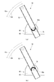
図7(a)は、軸線50aを中心とした張力付与部材50の角度θ(図3参照。)と、張力調整装置70が存在しないと仮定した場合に張力付与部材50が自重によって印刷媒体90に付与する荷重との関係を示すグラフである。図7(b)は、角度θと、圧縮コイルバネ71が張力付与部材50に付与する荷重との関係を示すグラフである。図7(c)は、角度θと、圧縮コイルバネ71から荷重が付与された張力付与部材50が印刷媒体90に付与する荷重との関係を示すグラフである。図7において、荷重は、張力付与部材50が自重によって印刷媒体90に張力を付与する場合に張力付与部材50が自重によって軸線50aを中心として回転する矢印10c(図3参照。)で示す方向の荷重を正の値の荷重としている。
図7(a)および図7(b)に示すように、圧縮コイルバネ71は、矢印10cで示す方向とは反対方向である矢印10d(図3参照。)で示す方向に張力付与部材50に荷重を付与するようになっている。そして、図7(b)に示すように、圧縮コイルバネ71が張力付与部材50に付与する荷重の大きさは、張力付与部材50が自重によって印刷媒体90に付与する張力が大きい角度θであるほど(すなわち、図7においては角度θの値が小さいほど)、大きい。したがって、圧縮コイルバネ71から荷重が付与された張力付与部材50が印刷媒体90に付与する荷重は、図7(c)に示すように、角度θによらず、略一定になっている。すなわち、圧縮コイルバネ71から荷重が付与された張力付与部材50によって印刷媒体90に付与される張力は、角度θによらず、略一定である。
なお、張力付与部材50は、図示していないストッパーの働きによって、角度θが例えば52°より小さくならないようになっている。圧縮コイルバネ71が張力付与部材50に荷重を付与可能な範囲は、例えば、角度θが52°から70°までの範囲である。また、張力付与部材50は、後述するように、巻き取り機構40による印刷媒体90の巻き取りによって、圧縮コイルバネ71が張力付与部材50に荷重を付与可能な範囲のうち特定の範囲(例えば62.5°から70°までの範囲)内に角度θが維持されるようになっている。
本実施形態では、張力付与部材50に荷重を付与する荷重付与手段の一部としての圧縮コイルバネ71は、一端がバー72のフランジ72aに接触していて、他端が脚側固定部材73に接触している構造としたが、これに限定されない。
図8(a)は、図3に示す荷重付与手段とは異なる荷重付与手段の外観斜視図である。図8(b)は、図8(a)に示す荷重付与手段の側面断面図である。
図8に示す荷重付与手段は、圧縮コイルバネ71と、円柱状の溝77aが形成されている円柱状の部材77と、環状の溝78aが形成されている円柱状の部材78と、図示していない脚側固定部材73とによって構成されている。
部材77は、図6に示すバー72の一端と同様にアーム側固定部材74に固定接続された端部77bと、端部77bとともに溝77aを形成する側壁77cとを備えている。部材77の側壁77cの少なくとも一部は、部材78の溝78aに挿入されている。部材77は、溝77a内に圧縮コイルバネ71を収納している。部材77の側壁77cは、一部が開口していて外部から圧縮コイルバネ71の少なくとも一部分が見えるようになっていても良い。例えば、側壁77cは、メッシュ状であっても良い。
部材78は、端部78bと、端部78bに接続されている円柱状の芯78cと、端部78bおよび芯78cとともに溝78aを形成する側壁78dとを備えている。部材78の芯78cの少なくとも一部は、部材77の溝77aに挿入されている。部材78の側壁78dは、脚側固定部材73に固定されている。部材78の側壁78dは、部材77の側壁77cと同様に一部が開口していても良い。
図8に示す圧縮コイルバネ71は、張力付与部材50によって印刷媒体90に張力を付与している場合には、一端が部材77の端部77bに接触していて、他端が部材78の芯78cに接触している。
部材77および部材78は、圧縮コイルバネ71の移動を所定の範囲内に規制する規制部材を構成している。部材77は、圧縮コイルバネ71の伸縮方向を規制している。また、部材77および部材78は、圧縮コイルバネ71の伸縮方向における圧縮コイルバネ71の移動範囲を規制している。
図9(a)は、図3および図8に示す荷重付与手段とは異なる荷重付与手段を示す図である。図9(b)は、図3、図8および図9(a)に示す荷重付与手段とは異なる荷重付与手段を示す図である。
例えば、図9(a)に示すように、軸線50a上に延在している軸52aを中心軸として、その中心軸の鉛直方向下方側の円弧上に荷重付与手段の一部としての圧縮コイルバネ75を配し、一端を角度検出装置60の一部に係止し、他端をアーム52に係止してもよい。なお、円弧上に圧縮コイルバネ75を配する場合、円弧状に形成されたガイド溝を設け、そのガイド溝に圧縮コイルバネ75を配せばよい。圧縮コイルバネ75は、縮められている状態で復元力によって伸びようとするので、その復元力によって、張力付与部材50の矢印10cで示す回転方向とは反対方向である矢印10dで示す方向に、張力付与部材50に荷重を付与することができる。
また、圧縮コイルバネの代わりに荷重付与手段の一部として引張コイルバネ76を用いる場合は、図9(b)に示すように、軸線50a上に延在している軸52aを中心軸として、その中心軸の鉛直方向上方側の円弧上に引張コイルバネ76を配し、一端を角度検出装置60の一部に係止し、他端をアーム52に係止すればよい。この場合にも、円弧状に形成されたガイド溝を設け、そのガイド溝に引張コイルバネ76を配せばよい。引張コイルバネ76は、伸ばされている状態で復元力によって縮もうとするので、その復元力によって、張力付与部材50の矢印10cで示す回転方向とは反対方向である矢印10dで示す方向に、張力付与部材50に荷重を付与することができる。
このように、軸52aを中心軸としてその円弧上にコイルバネを配する構成にすれば、張力調整装置70をコンパクト化することが可能である。ただし、コイルバネの先端にフック部分を設けてアーム52にコイルバネのフック部分を引っ掛けることによって、アーム52にコイルバネを係止させると、コイルバネのフック部分に応力集中が生じやすくなるため、コイルバネの寿命に関して影響が出る虞がある。そのため、長期間の使用や保守の観点からは図3に示すように、荷重付与手段としては圧縮コイルバネ71にバー72が挿入された状態が好ましい。
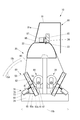
図10は、張力付与部材50が退避位置に存在する場合のインクジェットプリンター10の側面断面図である。
図10に示すように、張力付与部材50は、図示していないストッパーの働きによって、角度θが例えば95°より大きくならないようになっている。図10に示す張力付与部材50の位置を、退避位置と言う。張力付与部材50は、退避位置に存在する場合、印刷媒体90に接触することができないので、印刷媒体90に張力を付与することができない。
このとき、圧縮コイルバネ71に挿入されているバー72の一端側が図3に示す状態よりも圧縮コイルバネ71から露出しており、圧縮コイルバネ71の一端がバー72のフランジ72aに接触しておらず、他端が脚側固定部材73のバー支持部材73bに接触している状態となる。張力付与部材50が印刷媒体90に張力を付与しない場合には、圧縮コイルバネ71に張力付与部材50の荷重がかかっていない状態となるため、張力付与部材50が印刷媒体90に張力を付与しない時間による圧縮コイルバネ71の寿命への影響を抑制することができる。
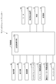
図11は、インクジェットプリンター10のブロック図である。
図11に示すように、インクジェットプリンター10は、上述した操作部82および表示部83と、PC(Personal Computer)などの外部の装置と通信を行う通信デバイスである通信部11と、上述したインクジェットヘッド87と、キャリッジ86(図2参照。)をガイドレール85(図2参照。)に沿って矢印10a(図2参照。)で示す主走査方向に移動させるためのキャリッジ駆動装置12と、搬送ローラー23(図3参照。)を回転させるための搬送ローラー駆動装置13と、搬送ローラー23の回転量を検出するエンコーダー14と、上述したモーター44および角度検出装置60と、時計15と、各種のデータを記憶するEEPROM(Electrically Erasable Programmable Read Only Memory)などの記憶デバイスである記憶部16と、インクジェットプリンター10全体を制御する制御部17とを備えている。
ここで、搬送ローラー23によって搬送された印刷媒体90の長さは、搬送ローラー23のうち印刷媒体90に接触した点の周方向における累積の長さと同一であるので、搬送ローラー23の径と、エンコーダー14の検出値とに基づいて、算出されることが可能である。具体的には、搬送ローラー23によって搬送された印刷媒体90の長さをL1とし、搬送ローラー23の径をR1とし、エンコーダー14の検出値から得られる回転角度をθ1[rad]とすると、L1は、「θ1×R1」である。
制御部17は、例えば、CPU(Central Processing Unit)と、プログラムおよび各種のデータを予め記憶しているROM(Read Only Memory)と、CPUの作業領域として用いられるRAM(Random Access Memory)とを備えている。CPUは、ROMまたは記憶部16に記憶されているプログラムを実行するようになっている。
制御部17は、ROMまたは記憶部16に記憶されているプログラムを実行することによって、印刷媒体90の搬送を制御する搬送制御手段17aとして機能する。
次に、インクジェットプリンター10の動作について説明する。
インクジェットプリンター10の制御部17は、外部から送信されてきた印刷データを通信部11を介して受信すると、この印刷データに基づいてインクジェットヘッド87、キャリッジ駆動装置12、搬送ローラー駆動装置13および巻き取り機構40を制御することによって、インクジェットヘッド87による印刷を実行する。
具体的には、制御部17は、キャリッジ駆動装置12を制御してキャリッジ86をガイドレール85に沿って矢印10aで示す主走査方向に移動させることによって、キャリッジ86に搭載されているインクジェットヘッド87を印刷媒体90に対して主走査方向に相対的に移動させる。このとき、制御部17は、印刷媒体90に向けてインクジェットヘッド87によってインク滴を吐出させることによって、主走査方向における印刷を実行する。そして、制御部17は、主走査方向における印刷が終了する度に、搬送ローラー駆動装置13を制御して搬送ローラー23を回転させることによって、搬送ローラー23と、ピンチローラー24とによって挟まれている印刷媒体90を矢印10bで示す副走査方向に移動させる。すなわち、制御部17は、インクジェットヘッド87と、印刷媒体90とを副走査方向に相対移動させることによって、インクジェットヘッド87による印刷媒体90への副走査方向における印刷位置を変更する。そして、制御部17は、副走査方向における新たな印刷位置において再び主走査方向における印刷を実行する。
ここで、搬送ローラー23によって印刷媒体90が搬送されると、繰り出し機構30のロールホルダー32およびロールホルダー33によって回転可能に支持されている紙管に巻き付けられている印刷媒体90が繰り出し機構30から繰り出される。
また、搬送ローラー23によって印刷媒体90が搬送されると、インクジェットヘッド87による印刷後の印刷媒体90は、巻き取り機構40および張力付与部材50の少なくとも一方によって張力が付与されるとともに、巻き取り機構40によって巻き取られる。
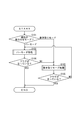
図12は、搬送制御手段17aの動作のフローチャートである。
搬送制御手段17aは、印刷の実行が開始されると、図12に示す動作を実行する。
図12に示すように、搬送制御手段17aは、印刷媒体90に張力を付与するための現在の張力付与モードを判断する(S101)。ここで、張力付与モードには、張力付与部材50によって印刷媒体90に張力を付与する「バーモード」と、巻き取り機構40によって印刷媒体90に張力を付与する「巻き取りモード」とが存在する。制御部17は、操作部82を介して「バーモード」および「巻き取りモード」の何れかの指定を受け付けることができる。なお、制御部17は、角度検出装置60によって検出された角度θが特定の角度、例えば、55°を超えている場合にのみ、「バーモード」の指定を受け付けることができる。特定の角度は、上述した特定の範囲の下限より小さい角度であって、フォトインターラプター64によって検出される角度である。
搬送制御手段17aは、現在の張力付与モードが「バーモード」であるとS101において判断すると、「バーモード」の処理であるバーモード処理を実行する(S102)。
バーモード処理において、搬送制御手段17aは次のように動作する。
搬送制御手段17aは、角度検出装置60によって検出された角度θが特定の範囲内であるか否かを判断する。ここで、角度θが特定の範囲内であるか否かは、フォトインターラプター62およびフォトインターラプター63からの検出値によって判断されることができる。
搬送制御手段17aは、角度θが特定の範囲内であると判断すると、現在の張力付与モードを判断する。搬送制御手段17aは、現在の張力付与モードが「巻き取りモード」であると判断すると、フラグを倒して、バーモード処理を終了する。搬送制御手段17aは、現在の張力付与モードが「バーモード」であると判断すると、印刷が終了していない場合には、バーモード処理を継続して実行し、印刷が終了した場合には、フラグを立てて、バーモード処理を終了する。
一方、搬送制御手段17aは、角度θが特定の範囲内ではないと判断すると、巻き取り機構40によって印刷媒体90を巻き取るための動力をモーター44に発生させることによって、巻き取り機構40の動作を開始する。このとき、搬送制御手段17aは、巻き取り機構40の動作を、開始してから特定の時間だけ、例えば、10秒間だけ継続させる。なお、特定の時間は時計15の値に基づいている。
ここで、巻き取り機構40の動作を特定の時間継続させる理由について説明する。
図14は、軸線50aを中心とした張力付与部材50の角度θが特定の範囲の下限を下回っている場合のインクジェットプリンター10の側面断面図である。
「特定の範囲」および「特定の時間」は、図14に示すように角度θが特定の範囲の下限を下回っている場合に、巻き取り機構40によって特定の時間、印刷媒体90が巻き取られると、図3に示すように角度θが特定の範囲内になるように、設定されている。したがって、巻き取り機構40の動作を特定の時間継続させる理由は、角度θが特定の範囲の下限を下回っている場合に、角度θを特定の範囲内にするためである。
搬送制御手段17aは、特定の時間の経過後に角度θが特定の範囲内ではないと判断すると、フラグを倒して、バーモード処理を終了する。
図12に示すように、搬送制御手段17aは、現在の張力付与モードが「巻き取りモード」であるとS101において判断すると、「巻き取りモード」の処理である巻き取りモード処理を実行する(S103)。
巻き取りモードの処理では、搬送制御手段17aは、巻き取り機構40によって印刷媒体90を巻き取るための動力をモーター44に発生させることによって、巻き取り機構40の動作を開始する。
次いで、搬送制御手段17aは、現在の張力付与モードを判断する。
搬送制御手段17aは、現在の張力付与モードが「バーモード」であると判断すると、フラグを倒した後、巻き取り機構40の動作を終了して、巻き取りモード処理を終了する。
搬送制御手段17aは、現在の張力付与モードが「巻き取りモード」であると判断すると、巻き取り処理を継続させ、印刷が終了したと判断すると、フラグを立てた後、巻き取り機構40の動作を終了して、巻き取りモード処理を終了する。
搬送制御手段17aは、S102におけるバーモード処理の実行を終了すると、フラグが立っているか否かを判断する(S104)。
搬送制御手段17aは、フラグが倒れているとS104において判断すると、巻き取りモード処理を実行する(S103)。
搬送制御手段17aは、S103における巻き取りモード処理の実行を終了すると、フラグが立っているか否かを判断する(S105)。
搬送制御手段17aは、フラグが倒れているとS105において判断すると、バーモード処理を実行する(S102)。
搬送制御手段17aは、フラグが立っているとS104またはS105において判断すると、図12に示す動作を終了する。
バーモード処理において、搬送制御手段17aは、角度θが特定の範囲内に維持されるように巻き取り機構40を制御する。すなわち、搬送制御手段17aは、角度θが特定の範囲内である場合には、巻き取り機構40による巻き取りを停止し、角度θが特定の範囲内ではない場合には、巻き取り機構40による巻き取りを実行する。したがって、印刷媒体90は、角度θが特定の範囲内である場合には、張力付与部材50によって張力が付与されている状態で、搬送ローラー23によって搬送された分だけ搬送ローラー23から巻き取り機構40までの長さが長くなる。その結果、角度θは、徐々に小さくなって、特定の範囲の下限を下回って特定の範囲内ではなくなる。印刷媒体90は、角度θが特定の範囲内ではない場合(特定の範囲の下限を下回った状態)には、巻き取り機構40によって巻き取られるので、張力付与部材50によって張力が付与されている状態で、巻き取り機構40によって巻き取られた分だけ搬送ローラー23から巻き取り機構40までの長さが短くなる。その結果、角度θは、徐々に大きくなって、特定の範囲内になる。このように、印刷媒体90は、張力付与部材50によって張力が付与されている状態で、巻き取り機構40によって巻き取られる。
例えば、巻き取り機構40に回転可能に支持されている紙管に巻き付けられているロール状の印刷媒体90の径(以下、「巻径」と言う。)が図15に示すように大きくなると、ロール状の印刷媒体90の回転軸から外周までの距離が長くなるので、ロール状の印刷媒体90の重さが仮に一定であったとしても、巻き取り機構40の、ロール状の印刷媒体90の巻き取りで発生するトルクが一定である場合(トルクが制限された状態)には、巻き取り機構40によって印刷媒体90を巻き取る力が、巻き取りに必要な強さよりも弱くなる。そのため、角度θが特定の範囲内である場合であっても、巻径が大きくなると、印刷媒体90を巻き取るように巻き取り機構40が制御されても、角度θが大きくならない可能性(巻き取り機構40の巻き取りが出来ない可能性)がある。実際には、巻径が大きくなると、ロール状の印刷媒体90の重さが重くなるので、角度θが特定の範囲内である場合であっても、印刷媒体90を巻き取るように巻き取り機構40が制御されても、角度θが大きくならない可能性(巻き取り機構40の巻き取りが出来ない可能性)が更に高くなる。搬送制御手段17aは、角度θが特定の範囲内ではない状態で特定の時間が経過した後には、巻き取りモード処理によって、巻き取り機構40に印刷媒体90を巻き取らせるように巻き取り機構40を制御する。したがって、印刷媒体90は、トルクリミッター45によってトルクが制限されている巻き取り機構40によって張力が付与されている状態で、搬送ローラー23によって搬送された分だけ巻き取り機構40によって巻き取られる。
また、搬送制御手段17aは、バーモード処理を実行中に、例えば、インクジェットプリンター10の利用者が張力付与部材50を手動で動かすなどによって張力付与部材50の位置を図10に示す退避位置に変更した場合など、角度θが特定の範囲の上限を上回って特定の範囲内ではなくなり、印刷媒体90にテンションバー53が接触しなくなった場合には、巻き取りモード処理によって、巻き取り機構40に印刷媒体90を巻き取らせるように巻き取り機構40を制御する。したがって、印刷媒体90は、トルクリミッター45によってトルクが制限されている巻き取り機構40によって張力が付与されている状態で、搬送ローラー23によって搬送された分だけ巻き取り機構40によって巻き取られる。
なお、利用者は、バーモード処理が実行されている場合に、操作部82を介して「巻き取りモード」を指定することによって、巻き取りモード処理に移行させることができる。同様に、利用者は、巻き取りモード処理が実行されている場合に、操作部82を介して「バーモード」を指定することによって、バーモード処理に移行させることができる。
ただし、巻き取りモード処理からバーモード処理に移行させられた場合に、図15に示すように巻径が大きいときには、角度θが特定の範囲内ではない状態で特定の時間が経過するので、上述したようにバーモード処理から巻き取りモード処理に戻ってしまう。したがって、利用者は、巻き取りモード処理からバーモード処理に移行させる場合に、巻径が大きいときには、例えば、張力付与部材50に取り付けられている図示していない重りを外したり、トルクリミッター45がモーター44側から印刷媒体90側への動力の伝達を遮断する場合のトルクリミッター45のトルクを強く調整したりして張力付与部材50を手動で軽くすることが好ましい。
また、巻き取りモード処理からバーモード処理に移行させられた場合に、張力付与部材50が図10に示すように退避位置に存在しているときには、角度θが特定の範囲内ではない状態で特定の時間が経過するので、上述したようにバーモード処理から巻き取りモード処理に戻ってしまう。したがって、利用者は、巻き取りモード処理からバーモード処理に移行させる場合に、張力付与部材50が退避位置に存在しているときには、図13に示すように張力付与部材50が印刷媒体90に接触する位置まで張力付与部材50を手動で移動させることが好ましい。
以上に説明したように、インクジェットプリンター10は、図7に示すように、圧縮コイルバネ71を備えていないと仮定した場合に角度θの変動によって張力付与部材50が自重によって印刷媒体90に付与する張力が大きくなる分の少なくとも一部を、角度θの変動に応じて圧縮コイルバネ71によって吸収するので、角度θの変動に対して、張力付与部材50から印刷媒体90に付与する張力を従来より安定化することができる。したがって、インクジェットプリンター10は、従来より安定化された張力が付与されている印刷媒体90に対して印刷を実行することによって、印刷の品質を従来より向上することができる。
また、インクジェットプリンター10は、圧縮コイルバネ71が張力付与部材50に荷重を付与可能である特定の範囲内に角度θを維持するので、張力付与部材50から印刷媒体90に付与する張力を更に確実に安定化することができる。
上述したように、巻径が大きいなどの原因によって、巻き取り機構40が印刷媒体90を巻き取ったとしても、角度θを特定の範囲内に維持することができなくなる場合がある。このような場合には、張力付与部材50は、印刷媒体90に張力を付与することができなくなる。しかしながら、インクジェットプリンター10は、張力付与部材50が印刷媒体90に張力を付与することができない場合であっても、巻き取り機構40による印刷媒体90の巻き取りによって印刷媒体90に張力を付与するので、印刷媒体90への張力の付与を継続することができる。したがって、インクジェットプリンター10は、張力付与部材50が自重によって印刷媒体90に張力を付与することができない場合であっても、印刷媒体90への印刷を継続することができる。
インクジェットプリンター10は、張力付与部材50に付与するための荷重を生成する手段が初張力を有していない圧縮コイルバネ71であるので、荷重付与手段が張力付与部材50に付与する荷重を、角度θの変動に応じて、滑らかに変動させることができる。したがって、インクジェットプリンター10は、張力付与部材に付与するための荷重を生成する手段が初張力を有する引張コイルバネである構成と比較して、印刷媒体90に付与する張力を安定化することができる。
ここで、インクジェットプリンター10は、圧縮コイルバネ71の伸縮方向および移動範囲を規制しない場合には、例えば、圧縮コイルバネ71が曲がった状態で圧縮されてしまったりするなどして、荷重付与手段によって張力付与部材50に荷重を付与するための所望の付勢力を圧縮コイルバネ71によって発揮することができない可能性がある。しかしながら、インクジェットプリンター10は、圧縮コイルバネ71の伸縮方向および移動範囲を規制するようになっているので、張力付与部材50の回転方向と逆方向に確実に荷重付与手段によって張力付与部材50に荷重を付与することができる。
なお、荷重付与手段は、引張コイルバネなど、圧縮コイルバネ以外のバネを使用して構成されても良い。
インクジェットプリンター10は、荷重付与手段がバネを使用して構成される場合、印刷媒体90に付与する張力を簡単な構成で安定化することができる。
なお、荷重付与手段は、張力付与部材50によって印刷媒体90に付与される張力を調整することができれば、バネを使用しない構成であっても良い。
インクジェットプリンター10は、以上において、図2に示すように角度検出装置60を矢印10aで示す主走査方向における両端に備えているが、図16に示すように張力調整装置70も主走査方向における両端に備えていても良い。インクジェットプリンター10は、張力調整装置70を主走査方向における両端に備えている場合、張力調整装置70によって張力付与部材50に付与する荷重を主走査方向における両端で揃えることができるので、張力付与部材50によって印刷媒体90に付与される張力を主走査方向において均一化することができ、好ましい。
インクジェットプリンター10は、以上において、図3に示すように張力調整装置70の荷重付与手段に張力付与部材50の荷重が鉛直方向の上側からかかるようになっている。しかしながら、インクジェットプリンター10は、図17に示すように張力調整装置70の荷重付与手段に張力付与部材50の荷重が鉛直方向の下側からかかるようになっていても良い。図17に示す構成は、図3に示す構成と比較して、軸線50aを中心として荷重付与手段を点対称の位置に設けている。なお、図17に示す構成において、インクジェットプリンター10は、例えば、角度検出装置60の側壁65が繰り出し機構30側に延在させられて、延在させられた側壁65に荷重付与手段が固定されていれば良い。
インクジェットプリンター10は、本実施の形態において、巻き取り機構40を本発明の媒体巻き付け機構としているが、巻き取り機構40を本発明の媒体巻き付け機構とせずに繰り出し機構30を本発明の媒体巻き付け機構としても良いし、図18に示すように巻き取り機構40を本発明の媒体巻き付け機構としたまま繰り出し機構30も本発明の媒体巻き付け機構としても良い。インクジェットプリンター10は、繰り出し機構30を本発明の媒体巻き付け機構とする場合には、繰り出し機構30のロールホルダー32の回転軸32aと、ロールホルダー33の回転軸33aとの少なくとも一方を回転させるための駆動力を発生させるモーターを繰り出し機構30に備えていて、張力付与部材50、角度検出装置60および張力調整装置70と同様な構成を繰り出し側にも備えていると良い。インクジェットプリンター10は、繰り出し機構30を本発明の媒体巻き付け機構とする場合には、繰り出し機構30による印刷媒体90の繰り出し量を搬送ローラー23による印刷媒体90の搬送量より少なくするように繰り出し機構30のモーターを制御することによって、繰り出し機構30から搬送ローラー23までの印刷媒体90に付与する張力を強めることができる。一方、インクジェットプリンター10は、繰り出し機構30による印刷媒体90の繰り出し量を搬送ローラー23による印刷媒体90の搬送量より多くするように繰り出し機構30のモーターを制御するによって、繰り出し機構30から搬送ローラー23までの印刷媒体90に付与する張力を弱めることができる。
インクジェットプリンター10は、図18に示すように繰り出し機構30および巻き取り機構40の両方を本発明の媒体巻き付け機構とした場合、テキスタイル印刷(印刷媒体90が布である場合の印刷媒体90への直接印刷)など、印刷媒体90自体に張力をかけた状態で繰り出しする必要がある印刷に好ましい。なお、図18に示すように繰り出し機構30および巻き取り機構40の両方を本発明の媒体巻き付け機構とした場合には、張力調整装置70の位置を図17に示す位置に配置すると、繰り出し側の張力調整装置と、巻き取り側の張力調整装置とが互いに緩衝してしまう。そのため、図18に示すように、繰り出し側の荷重付与手段は、繰り出し側の張力付与部材に対して、巻き取り側の荷重付与手段とは反対側に設けられていて、巻き取り側の荷重付与手段は、巻き取り側の張力付与部材に対して、繰り出し側の荷重付与手段とは反対側に設けられていることが好ましい。図18に示すインクジェットプリンター10は、繰り出し側の張力付与部材と、巻き取り側の張力付与部材との間に繰り出し側の荷重付与手段と、巻き取り側の荷重付与手段とが配置されていないので、繰り出し側の張力付与部材と、巻き取り側の張力付与部材との間に繰り出し側の荷重付与手段と、巻き取り側の荷重付与手段とが配置される構成と比較して、繰り出し側の張力付与部材と、巻き取り側の張力付与部材との間の距離を短縮することができる。したがって、図18に示すインクジェットプリンター10は、小型化することができる。
インクジェットプリンター10は、本実施の形態において、印刷媒体90を矢印10bで示す副走査方向に搬送することによってインクジェットヘッド87と、印刷媒体90とを副走査方向に相対移動させる構成であるが、この構成以外の構成であっても良い。例えば、インクジェットプリンター10は、インクジェットヘッド87を副走査方向に移動させることによってインクジェットヘッド87と、印刷媒体90とを副走査方向に相対移動させる構成であっても良い。
10 インクジェットプリンター
10c 矢印(張力付与部材が自重によって媒体に張力を付与する場合に張力付与部材が自重によって軸線を中心として回転する方向を示す矢印)
10d 矢印(張力付与部材が自重によって媒体に張力を付与する場合に張力付与部材が自重によって軸線を中心として回転する方向の反対方向を示す矢印)
17a 搬送制御手段
20 媒体搬送装置
30 繰り出し機構(媒体巻き付け機構)
40 巻き取り機構(媒体巻き付け機構)
50 張力付与部材
50a 軸線
60 角度検出装置(角度検出手段)
70 張力調整装置(荷重付与手段)
71 圧縮コイルバネ
72 バー(規制部材)
73 脚側固定部材(規制部材)
75 圧縮コイルバネ
77 部材(規制部材)
78 部材(規制部材)
90 印刷媒体(媒体)
10c 矢印(張力付与部材が自重によって媒体に張力を付与する場合に張力付与部材が自重によって軸線を中心として回転する方向を示す矢印)
10d 矢印(張力付与部材が自重によって媒体に張力を付与する場合に張力付与部材が自重によって軸線を中心として回転する方向の反対方向を示す矢印)
17a 搬送制御手段
20 媒体搬送装置
30 繰り出し機構(媒体巻き付け機構)
40 巻き取り機構(媒体巻き付け機構)
50 張力付与部材
50a 軸線
60 角度検出装置(角度検出手段)
70 張力調整装置(荷重付与手段)
71 圧縮コイルバネ
72 バー(規制部材)
73 脚側固定部材(規制部材)
75 圧縮コイルバネ
77 部材(規制部材)
78 部材(規制部材)
90 印刷媒体(媒体)
Claims (8)
- 帯状の媒体がロール状に巻き付けられて前記媒体に対して繰り出しおよび巻き取りの少なくとも一方を実行する媒体巻き付け機構と、
前記媒体のうち前記媒体巻き付け機構に巻き付けられていない部分を特定の軸線を中心とした回転方向に自重によって押すことによって前記媒体に張力を付与可能である張力付与部材と、
前記張力付与部材が前記媒体に張力を付与している場合の前記張力付与部材の自重による前記軸線を中心とした回転方向とは反対方向に前記張力付与部材に荷重を付与する荷重付与手段とを備えており、
前記荷重付与手段は、前記軸線を中心とした前記張力付与部材の角度が、前記張力付与部材が自重によって前記媒体に付与する張力が大きい角度であるほど、大きい荷重を前記張力付与部材に付与することを特徴とする媒体搬送装置。 - 前記軸線を中心とした前記張力付与部材の角度を検出する角度検出手段と、
前記媒体巻き付け機構を制御する搬送制御手段とを備えており、
前記搬送制御手段は、前記角度検出手段によって検出された角度が、前記荷重付与手段が前記張力付与部材に荷重を付与可能な範囲のうち特定の範囲内に維持されるように前記媒体巻き付け機構を制御することを特徴とする請求項1に記載の媒体搬送装置。 - 前記荷重付与手段は、
前記張力付与部材に付与するための荷重を生成する圧縮コイルバネと、
前記圧縮コイルバネの移動を所定の範囲内に規制する規制部材とを有することを特徴とする請求項1または請求項2に記載の媒体搬送装置。 - 前記規制部材は、前記圧縮コイルバネの伸縮方向を規制し、かつ、前記伸縮方向における前記圧縮コイルバネの移動範囲を規制するものであることを特徴とする請求項3に記載の媒体搬送装置。
- 前記圧縮コイルバネは、前記規制部材によって保持されており、
前記圧縮コイルバネは、前記張力付与部材が前記媒体に張力を付与しない場合において、前記張力付与部材から荷重がかかっていない状態となることを特徴とする請求項3に記載の媒体搬送装置。 - 前記媒体巻き付け機構は、前記媒体に対して繰り出しおよび巻きとりの両方を実行し、
前記張力付与部材および前記荷重付与手段は、前記媒体巻き付け機構による前記媒体の繰り出し側および巻き取り側の両方に設けられていて、
繰り出し側の前記荷重付与手段は、繰り出し側の前記張力付与部材に対して、巻き取り側の前記荷重付与手段とは反対側に設けられていて、
巻き取り側の前記荷重付与手段は、巻き取り側の前記張力付与部材に対して、繰り出し側の前記荷重付与手段とは反対側に設けられていることを特徴とする請求項1または請求項2に記載の媒体搬送装置。 - 前記媒体巻き付け機構は、前記媒体に対して巻き取りを実行し、
前記搬送制御手段は、前記角度検出手段によって検出された角度が特定の時間以上前記特定の範囲外である場合に、前記媒体巻き付け機構による前記媒体の巻き取りによって前記媒体に張力を付与することを特徴とする請求項2に記載の媒体搬送装置。 - 請求項1または請求項2に記載の媒体搬送装置と、
前記媒体搬送装置によって張力が付与されている前記媒体に対してインクによる印刷を実行するインクジェットヘッドとを備えていることを特徴とするインクジェットプリンター。
Priority Applications (1)
| Application Number | Priority Date | Filing Date | Title |
|---|---|---|---|
| JP2016519315A JP6552057B2 (ja) | 2014-05-16 | 2015-05-15 | 媒体搬送装置およびインクジェットプリンター |
Applications Claiming Priority (2)
| Application Number | Priority Date | Filing Date | Title |
|---|---|---|---|
| JP2014102906 | 2014-05-16 | ||
| JP2014-102906 | 2014-05-16 |
Publications (1)
| Publication Number | Publication Date |
|---|---|
| WO2015174522A1 true WO2015174522A1 (ja) | 2015-11-19 |
Family
ID=54480058
Family Applications (1)
| Application Number | Title | Priority Date | Filing Date |
|---|---|---|---|
| PCT/JP2015/064039 Ceased WO2015174522A1 (ja) | 2014-05-16 | 2015-05-15 | 媒体搬送装置およびインクジェットプリンター |
Country Status (2)
| Country | Link |
|---|---|
| JP (1) | JP6552057B2 (ja) |
| WO (1) | WO2015174522A1 (ja) |
Cited By (1)
| Publication number | Priority date | Publication date | Assignee | Title |
|---|---|---|---|---|
| WO2024190576A1 (ja) * | 2023-03-10 | 2024-09-19 | 株式会社ミマキエンジニアリング | プリンタ、インクジェットプリンタ、及び保湿装置 |
Families Citing this family (1)
| Publication number | Priority date | Publication date | Assignee | Title |
|---|---|---|---|---|
| JP7846998B2 (ja) * | 2022-02-08 | 2026-04-16 | ローランドディー.ジー.株式会社 | 巻取装置および印刷システム |
Citations (3)
| Publication number | Priority date | Publication date | Assignee | Title |
|---|---|---|---|---|
| JPH05338884A (ja) * | 1992-06-08 | 1993-12-21 | M C K:Kk | ワーク繰出し装置におけるワークの弛み検出方法及びその装置 |
| JP2004107021A (ja) * | 2002-09-18 | 2004-04-08 | Mutoh Ind Ltd | 記録装置用巻き取り装置 |
| JP2009143147A (ja) * | 2007-12-14 | 2009-07-02 | Mimaki Engineering Co Ltd | プリンター装置 |
-
2015
- 2015-05-15 JP JP2016519315A patent/JP6552057B2/ja active Active
- 2015-05-15 WO PCT/JP2015/064039 patent/WO2015174522A1/ja not_active Ceased
Patent Citations (3)
| Publication number | Priority date | Publication date | Assignee | Title |
|---|---|---|---|---|
| JPH05338884A (ja) * | 1992-06-08 | 1993-12-21 | M C K:Kk | ワーク繰出し装置におけるワークの弛み検出方法及びその装置 |
| JP2004107021A (ja) * | 2002-09-18 | 2004-04-08 | Mutoh Ind Ltd | 記録装置用巻き取り装置 |
| JP2009143147A (ja) * | 2007-12-14 | 2009-07-02 | Mimaki Engineering Co Ltd | プリンター装置 |
Cited By (1)
| Publication number | Priority date | Publication date | Assignee | Title |
|---|---|---|---|---|
| WO2024190576A1 (ja) * | 2023-03-10 | 2024-09-19 | 株式会社ミマキエンジニアリング | プリンタ、インクジェットプリンタ、及び保湿装置 |
Also Published As
| Publication number | Publication date |
|---|---|
| JPWO2015174522A1 (ja) | 2017-04-20 |
| JP6552057B2 (ja) | 2019-07-31 |
Similar Documents
| Publication | Publication Date | Title |
|---|---|---|
| JP6469097B2 (ja) | 媒体搬送装置およびインクジェットプリンター | |
| CN103619743B (zh) | 用于热打印色带卷筒的可扩张卡盘 | |
| US20120187233A1 (en) | Recording apparatus and roll medium lifting device | |
| JP6413565B2 (ja) | 印刷装置 | |
| US20090272838A1 (en) | Roll-sheet feeding device and image forming apparatus | |
| JP6552057B2 (ja) | 媒体搬送装置およびインクジェットプリンター | |
| US20120199687A1 (en) | Rolled medium holder device and recording apparatus | |
| US20100054837A1 (en) | Thermal printer | |
| WO2013039155A1 (ja) | フィラメントワインディング装置のボビン解舒装置 | |
| JP2009023171A (ja) | 記録装置および被搬送媒体搬送装置 | |
| CN108656736B (zh) | 印刷装置以及印刷装置的控制方法 | |
| JP2010215367A (ja) | シート収納装置及び記録装置 | |
| JP5678618B2 (ja) | ロール紙スキュー補正方法及び画像形成装置 | |
| US20170282610A1 (en) | Printing device and control method of a printing device | |
| JP6118516B2 (ja) | プリンタ装置 | |
| US20110261136A1 (en) | Thermal head printer | |
| CN111792425A (zh) | 印刷装置以及印刷方法 | |
| JP2009269722A (ja) | ロールシート給送装置及び画像形成装置 | |
| JP6103993B2 (ja) | ペーパーフランジユニット | |
| JP3120074U (ja) | ロール紙保持機構 | |
| JP2025115501A (ja) | 印刷装置の制御方法 | |
| JP2018034956A (ja) | 用紙搬送機構 | |
| JP2016199369A (ja) | 搬送装置及び印刷装置 | |
| CN223201251U (zh) | 收卷装置以及印刷装置 | |
| JP2012106854A (ja) | ロール媒体送り装置、記録装置 |
Legal Events
| Date | Code | Title | Description |
|---|---|---|---|
| 121 | Ep: the epo has been informed by wipo that ep was designated in this application |
Ref document number: 15792052 Country of ref document: EP Kind code of ref document: A1 |
|
| ENP | Entry into the national phase |
Ref document number: 2016519315 Country of ref document: JP Kind code of ref document: A |
|
| NENP | Non-entry into the national phase |
Ref country code: DE |
|
| 122 | Ep: pct application non-entry in european phase |
Ref document number: 15792052 Country of ref document: EP Kind code of ref document: A1 |