WO2015170440A1 - 表示操作システム - Google Patents
表示操作システム Download PDFInfo
- Publication number
- WO2015170440A1 WO2015170440A1 PCT/JP2015/001978 JP2015001978W WO2015170440A1 WO 2015170440 A1 WO2015170440 A1 WO 2015170440A1 JP 2015001978 W JP2015001978 W JP 2015001978W WO 2015170440 A1 WO2015170440 A1 WO 2015170440A1
- Authority
- WO
- WIPO (PCT)
- Prior art keywords
- display
- detection result
- contact
- unit
- displacement
- Prior art date
- Legal status (The legal status is an assumption and is not a legal conclusion. Google has not performed a legal analysis and makes no representation as to the accuracy of the status listed.)
- Ceased
Links
Images


Classifications
-
- G—PHYSICS
- G06—COMPUTING OR CALCULATING; COUNTING
- G06F—ELECTRIC DIGITAL DATA PROCESSING
- G06F3/00—Input arrangements for transferring data to be processed into a form capable of being handled by the computer; Output arrangements for transferring data from processing unit to output unit, e.g. interface arrangements
- G06F3/01—Input arrangements or combined input and output arrangements for interaction between user and computer
- G06F3/03—Arrangements for converting the position or the displacement of a member into a coded form
- G06F3/033—Pointing devices displaced or positioned by the user, e.g. mice, trackballs, pens or joysticks; Accessories therefor
- G06F3/0354—Pointing devices displaced or positioned by the user, e.g. mice, trackballs, pens or joysticks; Accessories therefor with detection of two-dimensional [2D] relative movements between the device, or an operating part thereof, and a plane or surface, e.g. 2D mice, trackballs, pens or pucks
- G06F3/03547—Touch pads, in which fingers can move on a surface
-
- B—PERFORMING OPERATIONS; TRANSPORTING
- B60—VEHICLES IN GENERAL
- B60K—ARRANGEMENT OR MOUNTING OF PROPULSION UNITS OR OF TRANSMISSIONS IN VEHICLES; ARRANGEMENT OR MOUNTING OF PLURAL DIVERSE PRIME-MOVERS IN VEHICLES; AUXILIARY DRIVES FOR VEHICLES; INSTRUMENTATION OR DASHBOARDS FOR VEHICLES; ARRANGEMENTS IN CONNECTION WITH COOLING, AIR INTAKE, GAS EXHAUST OR FUEL SUPPLY OF PROPULSION UNITS IN VEHICLES
- B60K35/00—Instruments specially adapted for vehicles; Arrangement of instruments in or on vehicles
- B60K35/10—Input arrangements, i.e. from user to vehicle, associated with vehicle functions or specially adapted therefor
-
- B—PERFORMING OPERATIONS; TRANSPORTING
- B60—VEHICLES IN GENERAL
- B60K—ARRANGEMENT OR MOUNTING OF PROPULSION UNITS OR OF TRANSMISSIONS IN VEHICLES; ARRANGEMENT OR MOUNTING OF PLURAL DIVERSE PRIME-MOVERS IN VEHICLES; AUXILIARY DRIVES FOR VEHICLES; INSTRUMENTATION OR DASHBOARDS FOR VEHICLES; ARRANGEMENTS IN CONNECTION WITH COOLING, AIR INTAKE, GAS EXHAUST OR FUEL SUPPLY OF PROPULSION UNITS IN VEHICLES
- B60K35/00—Instruments specially adapted for vehicles; Arrangement of instruments in or on vehicles
- B60K35/20—Output arrangements, i.e. from vehicle to user, associated with vehicle functions or specially adapted therefor
- B60K35/21—Output arrangements, i.e. from vehicle to user, associated with vehicle functions or specially adapted therefor using visual output, e.g. blinking lights or matrix displays
- B60K35/22—Display screens
-
- B—PERFORMING OPERATIONS; TRANSPORTING
- B60—VEHICLES IN GENERAL
- B60K—ARRANGEMENT OR MOUNTING OF PROPULSION UNITS OR OF TRANSMISSIONS IN VEHICLES; ARRANGEMENT OR MOUNTING OF PLURAL DIVERSE PRIME-MOVERS IN VEHICLES; AUXILIARY DRIVES FOR VEHICLES; INSTRUMENTATION OR DASHBOARDS FOR VEHICLES; ARRANGEMENTS IN CONNECTION WITH COOLING, AIR INTAKE, GAS EXHAUST OR FUEL SUPPLY OF PROPULSION UNITS IN VEHICLES
- B60K35/00—Instruments specially adapted for vehicles; Arrangement of instruments in or on vehicles
- B60K35/60—Instruments characterised by their location or relative disposition in or on vehicles
-
- G—PHYSICS
- G06—COMPUTING OR CALCULATING; COUNTING
- G06F—ELECTRIC DIGITAL DATA PROCESSING
- G06F3/00—Input arrangements for transferring data to be processed into a form capable of being handled by the computer; Output arrangements for transferring data from processing unit to output unit, e.g. interface arrangements
- G06F3/01—Input arrangements or combined input and output arrangements for interaction between user and computer
- G06F3/018—Input/output arrangements for oriental characters
-
- G—PHYSICS
- G06—COMPUTING OR CALCULATING; COUNTING
- G06F—ELECTRIC DIGITAL DATA PROCESSING
- G06F3/00—Input arrangements for transferring data to be processed into a form capable of being handled by the computer; Output arrangements for transferring data from processing unit to output unit, e.g. interface arrangements
- G06F3/01—Input arrangements or combined input and output arrangements for interaction between user and computer
- G06F3/03—Arrangements for converting the position or the displacement of a member into a coded form
- G06F3/033—Pointing devices displaced or positioned by the user, e.g. mice, trackballs, pens or joysticks; Accessories therefor
- G06F3/0354—Pointing devices displaced or positioned by the user, e.g. mice, trackballs, pens or joysticks; Accessories therefor with detection of two-dimensional [2D] relative movements between the device, or an operating part thereof, and a plane or surface, e.g. 2D mice, trackballs, pens or pucks
-
- G—PHYSICS
- G06—COMPUTING OR CALCULATING; COUNTING
- G06F—ELECTRIC DIGITAL DATA PROCESSING
- G06F3/00—Input arrangements for transferring data to be processed into a form capable of being handled by the computer; Output arrangements for transferring data from processing unit to output unit, e.g. interface arrangements
- G06F3/01—Input arrangements or combined input and output arrangements for interaction between user and computer
- G06F3/03—Arrangements for converting the position or the displacement of a member into a coded form
- G06F3/033—Pointing devices displaced or positioned by the user, e.g. mice, trackballs, pens or joysticks; Accessories therefor
- G06F3/0362—Pointing devices displaced or positioned by the user, e.g. mice, trackballs, pens or joysticks; Accessories therefor with detection of one-dimensional [1D] translations or rotations of an operating part of the device, e.g. scroll wheels, sliders, knobs, rollers or belts
-
- G—PHYSICS
- G06—COMPUTING OR CALCULATING; COUNTING
- G06F—ELECTRIC DIGITAL DATA PROCESSING
- G06F3/00—Input arrangements for transferring data to be processed into a form capable of being handled by the computer; Output arrangements for transferring data from processing unit to output unit, e.g. interface arrangements
- G06F3/01—Input arrangements or combined input and output arrangements for interaction between user and computer
- G06F3/048—Interaction techniques based on graphical user interfaces [GUI]
- G06F3/0481—Interaction techniques based on graphical user interfaces [GUI] based on specific properties of the displayed interaction object or a metaphor-based environment, e.g. interaction with desktop elements like windows or icons, or assisted by a cursor's changing behaviour or appearance
- G06F3/0482—Interaction with lists of selectable items, e.g. menus
-
- G—PHYSICS
- G06—COMPUTING OR CALCULATING; COUNTING
- G06F—ELECTRIC DIGITAL DATA PROCESSING
- G06F3/00—Input arrangements for transferring data to be processed into a form capable of being handled by the computer; Output arrangements for transferring data from processing unit to output unit, e.g. interface arrangements
- G06F3/01—Input arrangements or combined input and output arrangements for interaction between user and computer
- G06F3/048—Interaction techniques based on graphical user interfaces [GUI]
- G06F3/0484—Interaction techniques based on graphical user interfaces [GUI] for the control of specific functions or operations, e.g. selecting or manipulating an object, an image or a displayed text element, setting a parameter value or selecting a range
- G06F3/04842—Selection of displayed objects or displayed text elements
-
- G—PHYSICS
- G06—COMPUTING OR CALCULATING; COUNTING
- G06F—ELECTRIC DIGITAL DATA PROCESSING
- G06F3/00—Input arrangements for transferring data to be processed into a form capable of being handled by the computer; Output arrangements for transferring data from processing unit to output unit, e.g. interface arrangements
- G06F3/01—Input arrangements or combined input and output arrangements for interaction between user and computer
- G06F3/048—Interaction techniques based on graphical user interfaces [GUI]
- G06F3/0487—Interaction techniques based on graphical user interfaces [GUI] using specific features provided by the input device, e.g. functions controlled by the rotation of a mouse with dual sensing arrangements, or of the nature of the input device, e.g. tap gestures based on pressure sensed by a digitiser
- G06F3/0488—Interaction techniques based on graphical user interfaces [GUI] using specific features provided by the input device, e.g. functions controlled by the rotation of a mouse with dual sensing arrangements, or of the nature of the input device, e.g. tap gestures based on pressure sensed by a digitiser using a touch-screen or digitiser, e.g. input of commands through traced gestures
-
- B—PERFORMING OPERATIONS; TRANSPORTING
- B60—VEHICLES IN GENERAL
- B60K—ARRANGEMENT OR MOUNTING OF PROPULSION UNITS OR OF TRANSMISSIONS IN VEHICLES; ARRANGEMENT OR MOUNTING OF PLURAL DIVERSE PRIME-MOVERS IN VEHICLES; AUXILIARY DRIVES FOR VEHICLES; INSTRUMENTATION OR DASHBOARDS FOR VEHICLES; ARRANGEMENTS IN CONNECTION WITH COOLING, AIR INTAKE, GAS EXHAUST OR FUEL SUPPLY OF PROPULSION UNITS IN VEHICLES
- B60K2360/00—Indexing scheme associated with groups B60K35/00 or B60K37/00 relating to details of instruments or dashboards
- B60K2360/143—Touch sensitive instrument input devices
- B60K2360/1438—Touch screens
-
- B—PERFORMING OPERATIONS; TRANSPORTING
- B60—VEHICLES IN GENERAL
- B60K—ARRANGEMENT OR MOUNTING OF PROPULSION UNITS OR OF TRANSMISSIONS IN VEHICLES; ARRANGEMENT OR MOUNTING OF PLURAL DIVERSE PRIME-MOVERS IN VEHICLES; AUXILIARY DRIVES FOR VEHICLES; INSTRUMENTATION OR DASHBOARDS FOR VEHICLES; ARRANGEMENTS IN CONNECTION WITH COOLING, AIR INTAKE, GAS EXHAUST OR FUEL SUPPLY OF PROPULSION UNITS IN VEHICLES
- B60K35/00—Instruments specially adapted for vehicles; Arrangement of instruments in or on vehicles
- B60K35/80—Arrangements for controlling instruments
Definitions
- This disclosure relates to a display operation system that selects an image in a display screen by an operation of an operator.
- an area selection mode for selecting one of a plurality of display areas in the display screen and a function selection mode for selecting an icon in the selected display area are provided. Selection in the area selection mode and in the function selection mode
- a system that performs selection by touchpad operation see, for example, Patent Document 1.
- the present disclosure has been made in view of such problems, and an object thereof is to suppress the occurrence of erroneous operations in selection of a display area and selection in the display area.
- the display operation system includes a contact detection unit, a displacement detection unit, a region selection unit, and a position specifying unit.
- the contact detection unit has an operation surface, and detects a contact position where the operator contacts on the operation surface.
- the displacement detection unit includes a connection member that is connected to the contact detection unit and is movable in a two-dimensional direction, and detects a two-dimensional coordinate indicating a displacement of the connection member.
- the area selection unit is a display screen of a display device that displays an image using a detection result of either a contact detection result that is a detection result by the contact detection unit or a displacement detection result that is a detection result by the displacement detection unit.
- One of a plurality of display areas set in the above is selected.
- the position specifying unit specifies a position in the display region selected by the region selecting unit using a detection result that is not used by the region selecting unit among the contact detection result and the displacement detection result.
- the contact detection unit detects a contact position on the operation surface, that is, a two-dimensional coordinate on the operation surface. Moreover, the display operation system of this indication detects the two-dimensional coordinate which shows the displacement of a connection member by a displacement detection part. Therefore, the operator who operates the display operation system can instruct the first two-dimensional coordinates by touching the operation surface of the contact detection unit, and further, by moving the connecting member of the displacement detection unit. Two two-dimensional coordinates can be indicated.
- the position in the display screen of the display device can be indicated by two-dimensional coordinates, a plurality of display areas set on the display screen by the first two-dimensional coordinates and the second two-dimensional coordinates, The position in the display area can be indicated.
- the selection of the display area in the display screen and the specification of the position in the selected display area include the instruction by touching the operation surface and the instruction by movement of the connecting member. You can share it with. Thereby, it is not necessary to perform both selection of the display area and specification of the position in the display area by an instruction by touching the operation surface, and the occurrence of an erroneous operation can be suppressed.
- FIG. 1 is a block diagram showing a schematic configuration of a remote control system.
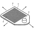
- FIG. 2 is a perspective view showing the configuration of the movable part.
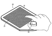
- FIG. 3 is a perspective view of the movable part showing the gripped state.
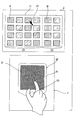
- FIG. 4 is a diagram illustrating a display screen and a movable portion of the display device.
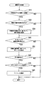
- FIG. 5 is a flowchart showing the operation input process.
- FIG. 6 is a plan view of a movable portion according to another embodiment.
- FIG. 7 is a perspective view of a movable portion according to another embodiment.
- the remote operation system 1 of this embodiment is mounted on a vehicle, and as shown in FIG. 1, a display device 2, an operation device 3, a remote operation control device 4, and an in-vehicle device 5 (for example, a navigation device, an audio device). And air conditioner).
- the display device 2 is a color display device having a display screen 11 such as a liquid crystal display, and displays various images on the display screen 11 in response to an input of a video signal from the remote operation control device 4.
- the display device 2 is disposed at a position intermediate between the driver's seat and the passenger seat on a dashboard (not shown) in front of the driver in the passenger compartment, and the driver can display the display screen 11 of the display device 2.
- the viewpoint movement when watching is reduced.
- the operation device 3 is disposed on the upper surface of a center console (not shown) immediately next to the driver's seat so that the driver can easily operate without extending his hand or changing his posture. It has become.
- the operating device 3 is a pointing device for inputting a cursor moving direction and a determination instruction on the display screen 11.
- the operating device 3 includes a touch pad 21, a movable unit 22, a position detection sensor 23, a push operation detection sensor 24, a reaction force generation unit 25, and an operation control unit 26.
- the touch pad 21 includes an operation surface for the driver to touch his fingertip.
- the touch pad 21 detects the position where the fingertip touches on the operation surface, and outputs contact position information indicating the contact position.
- the movable part 22 includes a placement part 31, a shaft part 32, and a grip part 33.
- the mounting portion 31 is formed in a flat plate shape, and the touch pad 21 is placed on the surface thereof.
- the upper end side of the shaft portion 32 is connected to the back surface of the placement portion 31.
- the shaft portion 32 is configured to be movable in a two-dimensional direction (directions indicated by symbols X and Y in the drawing) along a plane perpendicular to the axial direction of the shaft portion 32 with the lower end side as a fulcrum.
- the coordinate positions of the shaft portion 32 in the X-axis direction and the Y-axis direction take integer values from 0 to 255 in the X direction and from 0 to 255 in the Y direction.
- the shaft portion 32 is configured to return to a central fixed position (neutral position) in a state where no force in the two-dimensional direction is applied by the driver.
- the shaft portion 32 is configured to be movable downward in the axial direction (in the direction of arrow Z in FIG. 1), and in the state where a downward force is not applied by the driver, that is, in the state where the driver is not pressed down, the axial direction thereof. It returns to the upper fixed position.
- the grip part 33 is a part gripped by the driver. As shown in FIG. 2, the grip portion 33 is formed in a cylindrical shape, for example, and protrudes from the surface of the placement portion 31 such that the cylindrical axis is perpendicular to the surface of the placement portion 31. Yes. The grip portion 33 is disposed at a position adjacent to the touch pad 21 on the surface of the placement portion 31.
- the driver performs the touch operation on the touch pad 21 with the index finger by holding the grip part 33 so that the grip part 33 is sandwiched between the thumb and the index finger.
- the movable portion 22 can be moved in the two-dimensional direction.
- the position detection sensor 23 detects the coordinate position of the shaft portion 32 in the X-axis direction and the Y-axis direction, and outputs operation position information indicating the coordinate position.
- the push operation detection sensor 24 detects that the shaft portion 32 has been pushed in the Z-axis direction, and outputs push operation detection information indicating the detection result.
- the reaction force generation unit 25 supports the shaft portion 32 and applies a reaction force to the shaft portion 32 based on the coordinate positions of the shaft portion 32 in the X-axis direction and the Y-axis direction.
- the operation control unit 26 outputs the contact position information from the touch pad 21, the operation position information from the position detection sensor 23, and the push operation detection information from the push operation detection sensor 24 to the remote operation control device 4. Further, the operation control unit 26 causes the reaction force generation unit 25 to generate a reaction force for returning the shaft portion 32 to the neutral position when the shaft portion 32 is out of the neutral position based on the operation position information.
- the remote operation control device 4 is composed mainly of a well-known microcomputer comprising a CPU, ROM, RAM, I / O and a bus line connecting these components, and executes various processes for the driver to remotely operate. To do.
- the remote operation control device 4 is connected to the operation device 3 via a dedicated communication line 6 so as to be able to communicate with each other. Further, the remote operation control device 4 is connected to the in-vehicle device 5 via an in-vehicle LAN (Local Area Network) 7 so as to communicate with each other.
- LAN Local Area Network
- the remote operation control device 4 causes the display device 2 to display an operation image for operating the in-vehicle device 5. Then, the remote operation control device 4 causes the driver to select various icons arranged on the operation screen via the operation device 3, and accepts an execution instruction for the selected icon, so that the designated icon is displayed. The in-vehicle device 5 is caused to execute the assigned function.
- the remote operation control device 4 displays two operation images G1 and G2 having different functions on the display screen 11 of the display device 2, for example, as shown in FIG.
- the operation image G1 is arranged on the left side of the display screen 11, and the operation image G2 is arranged on the right side of the display screen 11.
- the operation image G1 includes a plurality of selectable icons I1
- the operation image G2 includes a plurality of selectable icons I2.
- the operation image G1 is an image for inputting a character indicating the destination when searching for the destination with a navigation device, for example, and the icon I1 indicates a selectable Kana character.
- the operation image G2 indicates a character string candidate including the kana character selected in the operation image G1 by an icon I2.
- the driver can use the operation device 3 to select either the operation image G1 or the operation image G2, and then select an icon included in the selected operation image.
- the remote operation control device 4 executes input operation processing.
- This operation input process is a process repeatedly executed during the operation of the remote operation control device 4.
- the remote operation control device 4 first moves the movable portion 22 from the neutral position based on the operation position information from the position detection sensor 23 in S10. Determine whether or not.
- the process proceeds to S40.
- the movable unit 22 has moved from the neutral position (S10: YES)
- the process proceeds to S40.
- the operation image is selected based on the moving direction of the movable portion 22 with the neutral position as a base point.
- the process proceeds to S40. For example, as illustrated in FIG. 4, it is assumed that the operation image G ⁇ b> 1 is disposed on the left side of the display screen 11 and the operation image G ⁇ b> 2 is disposed on the right side of the display screen 11.
- the operation image G1 is selected when the moving direction of the movable unit 22 is the direction toward the left with the neutral position as the base point, and the operation image G2 is selected when the direction is the right direction with the neutral position as the base point. To do.
- S60 based on the push operation detection information from the push operation detection sensor 24, it is determined whether or not the movable portion 22 has been pushed in the Z-axis direction.
- the operation input process is temporarily ended.
- the movable part 22 is pressed (S60: YES)
- the touch pad 21 has an operation surface, and detects a contact position where the driver contacts on the operation surface.
- the operating device 3 includes a movable unit 22 that is connected to the touch pad 21 and can move in a two-dimensional direction, and detects two-dimensional coordinates indicating the displacement of the movable unit 22.
- the remote operation control device 4 selects one of the operation image G1 and the operation image G2 using the detection result by the operation device 3 (S30). Furthermore, the remote operation control device 4 specifies the position indicated by the pointer PT in the selected operation image using the detection result by the touch pad 21 (S50).
- the remote operation system 1 first detects the contact position on the operation surface, that is, the two-dimensional coordinates on the operation surface, by the touch pad 21. Further, the remote operation system 1 detects a two-dimensional coordinate indicating the displacement of the movable portion 22 by the operation device 3. Therefore, the driver who operates the remote operation system 1 can instruct the first two-dimensional coordinates by touching the operation surface of the touch pad 21, and further, the second unit can be moved by moving the movable unit 22. Two-dimensional coordinates can be indicated.
- the operation image displayed on the display screen 11 by the first two-dimensional coordinates and the second two-dimensional coordinates.
- G1, G2 and the position in the operation images G1, G2 can be indicated.
- the selection of the operation image in the display screen 11 and the specification of the position in the selected operation image are performed by the instruction by the touch on the operation surface of the touch pad 21 and the movable unit 22. It is possible to share with instructions by movement. Thereby, it is not necessary to perform both selection of the operation image and specification of the position in the operation image by an instruction by touching the operation surface of the touch pad 21, and the occurrence of an erroneous operation can be suppressed.
- the movable unit 22 includes a placement unit 31 and a gripping unit 33.
- the placement unit 31 places the touch pad 21 so that the driver can contact the operation surface of the touch pad 21.
- the grip portion 33 is disposed on the side of the placement unit 31 where the operation surface of the touch pad 21 is disposed and adjacent to the operation surface of the touch pad 21 and is gripped by the driver.
- the driver can operate the movable portion 22 by gripping the grip portion 33.
- the operation surface of the touchpad 21 is arrange
- the touchpad 21 can be operated by touching the operation surface of the touchpad 21 with a fingertip of a hand.
- the remote operation system 1 is a display operation system
- the touch pad 21 is a main contact detection unit
- the operation device 3 is a displacement detection unit
- the movable member 22 is a connecting member
- the processing of S30 is a region selection unit (means)
- the operation images G1 and G2 are display areas
- the process of S50 is a position specifying unit (means).
- the movable portion 22 includes the grip portion 33.
- the grip portion 33 may be omitted and the placement portion 31 may be gripped.
- the movable unit 22 may be provided with a selection button 34 for selecting an icon indicated by the pointer PT.
- the operation image is selected by moving the movable portion 22 and the pointer PT is moved by operating the touch pad 21.
- the pointer PT may be moved by moving the movable unit 22 and the operation image may be selected by operating the touch pad 21.
- two operation images are displayed on the display screen 11 and the operation image is selected based on the moving direction of the movable unit 22 with the neutral position as a base point.
- three or more operation images may be displayed on the display screen 11.
- two-dimensional coordinates indicating the displacement of the shaft portion 32 are specified, and the two-dimensional coordinates are associated with the two-dimensional coordinates on the display screen 11. You can. Then, when an operation image desired by the driver is instructed on the display screen 11, the driver can select the operation image by pressing the shaft portion 32 in the Z-axis direction.
Landscapes
- Engineering & Computer Science (AREA)
- General Engineering & Computer Science (AREA)
- Theoretical Computer Science (AREA)
- Human Computer Interaction (AREA)
- Physics & Mathematics (AREA)
- General Physics & Mathematics (AREA)
- Chemical & Material Sciences (AREA)
- Combustion & Propulsion (AREA)
- Transportation (AREA)
- Mechanical Engineering (AREA)
- User Interface Of Digital Computer (AREA)
- Position Input By Displaying (AREA)
Abstract
接触検出部(21)と、変位検出部(3)と、領域選択部(S30)と、位置特定部(S50)とを備える表示操作システム(1)を提供する。接触検出部は、操作者が操作面上において接触した接触位置を検出する。変位検出部は、接触検出部と連結されて二次元方向に移動可能な連結部材を有し、連結部材の変位を検出する。領域選択部は、接触検出部による接触検出結果と、変位検出部による変位検出結果との何れか一方を用いて、画像を表示する表示装置の表示画面に設定された複数の表示領域の何れかを選択する。位置特定部は、接触検出結果および変位検出結果のうち、他方の検出結果を用いて、領域選択部により選択された表示領域内における位置を特定する。
Description
本出願は、2014年5月9日に出願された日本国特許出願2014-97876号に基づくものであり、この開示をここに参照により援用する。
本開示は、表示画面内の画像を操作者の操作により選択する表示操作システムに関する。
従来、表示画面内の複数の表示領域の何れかを選択する領域選択モードと、選択された表示領域内のアイコンを選択する機能選択モードと備え、領域選択モード時の選択と、機能選択モード時の選択をタッチパッド操作により行うシステムが知られている(例えば、特許文献1を参照)。
しかし、本願発明者の検討によれば、上記特許文献1に記載の技術では、表示領域の選択と、選択された表示領域内のアイコンの選択とを同じタッチパッドの操作面上で行うため、選択操作を誤ってしまうおそれがあった。
本開示は、こうした問題に鑑みてなされたものであり、表示領域の選択と表示領域内の選択とにおいて誤操作の発生を抑制することを目的とする。
本開示の一例に係る表示操作システムは、接触検出部と、変位検出部と、領域選択部と、位置特定部とを備える。
接触検出部は、操作面を有し、操作者が操作面上において接触した接触位置を検出する。変位検出部は、接触検出部と連結されて二次元方向に移動可能な連結部材を有し、連結部材の変位を示す二次元座標を検出する。
領域選択部は、接触検出部による検出結果である接触検出結果と、変位検出部による検出結果である変位検出結果との何れか一方の検出結果を用いて、画像を表示する表示装置の表示画面に設定された複数の表示領域の何れかを選択する。さらに位置特定部は、接触検出結果および変位検出結果のうち、領域選択部で用いられない方の検出結果を用いて、領域選択部により選択された表示領域内における位置を特定する。
このように構成された表示操作システムは、まず接触検出部により、操作面上における接触位置、すなわち、操作面上における二次元座標を検出する。また本開示の表示操作システムは、変位検出部により、連結部材の変位を示す二次元座標を検出する。したがって、表示操作システムを操作する操作者は、接触検出部の操作面に接触することにより第1の二次元座標を指示することができ、さらに、変位検出部の連結部材を移動させることにより第2の二次元座標を指示することができる。
そして、表示装置の表示画面内の位置は二次元座標で指示することができるため、上記第1の二次元座標と上記第2の二次元座標により、表示画面に設定された複数の表示領域と、表示領域内における位置を指示することができる。
このため、上述の表示操作システムによれば、表示画面内における表示領域の選択と、選択された表示領域内における位置の特定とを、操作面への接触による指示と連結部材の移動による指示とで分担して行うことができる。これにより、表示領域の選択と表示領域内における位置の特定との両方を、操作面への接触による指示で行う必要がなくなり、誤操作の発生を抑制することができる。
本開示についての上記および他の目的、特徴や利点は、添付の図面を参照した下記の詳細な説明から、より明確になる。添付図面において
図1は、遠隔操作システムの概略構成を示すブロック図である。
図2は、可動部の構成を示す斜視図である。
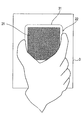
図3は、把持された状態を示す可動部の斜視図である。
図4は、表示装置の表示画面と可動部を示す図である。
図5は、操作入力処理を示すフローチャートである。
図6は、別の実施形態の可動部の平面図である。
図7は、別の実施形態の可動部の斜視図である。
以下に実施形態を図面とともに説明する。
本実施形態の遠隔操作システム1は、車両に搭載され、図1に示すように、表示装置2と、操作装置3と、遠隔操作制御装置4と、車載装置5(例えば、ナビゲーション装置、オーディオ装置、空調装置など)とを備える。
表示装置2は、液晶ディスプレイ等の表示画面11を有するカラー表示装置であり、遠隔操作制御装置4からの映像信号の入力に応じて各種画像を表示画面11に表示する。
表示装置2は、車室内において、運転者の前方にあるダッシュボード(不図示)上で運転席と助手席との中間となる位置に配置されており、運転者が表示装置2の表示画面11を見る際の視点移動が軽減されるようになっている。一方、操作装置3は、運転席のすぐ横にあるセンターコンソール(不図示)の上面に配置されており、運転者が遠方へ手を伸ばしたり姿勢を変えたりすることなく容易に操作できるようになっている。
操作装置3は、表示画面11上でカーソルの移動方向および決定指示を入力するためのポインティングデバイスである。操作装置3は、タッチパッド21、可動部22、位置検出センサ23、押操作検出センサ24、反力発生ユニット25および操作制御部26を備える。
タッチパッド21は、運転者がその指先を接触させるための操作面を備える。そしてタッチパッド21は、操作面上において指先が接触した位置を検出し、この接触位置を示す接触位置情報を出力する。
可動部22は、載置部31と、軸部32と、把持部33とを備える。
載置部31は、図2に示すように、平板状に形成されており、その表面にタッチパッド21が載置される。
軸部32は、図1に示すように、その上端側が載置部31の裏面に連結される。また軸部32は、その下端側を支点にして軸部32の軸方向と垂直な平面に沿って二次元方向(図中の記号X,Yで示す方向)に移動可能に構成されている。
そして、軸部32のX軸方向およびY軸方向それぞれの座標位置は、X方向に0~255、Y方向に0~255の整数値をとる。なお軸部32は、運転者により二次元方向への力が加えられていない状態では中央の定位置(中立位置)に戻るようにされている。
また軸部32は、その軸方向下向き(図1の矢印Zの方向)にも移動可能に構成され、運転者により下向きの力が加えられていない状態、すなわち押下されていない状態ではその軸方向上方の定位置に戻るようにされている。
把持部33は、運転者により把持される部位である。把持部33は、図2に示すように、例えば円筒状に形成されており、その円筒軸が載置部31の表面に対して垂直となるようにして、載置部31の表面から突出している。そして把持部33は、載置部31の表面上においてタッチパッド21と隣接する位置に配置される。
これにより、図3に示すように、運転者は、自身の親指と人差指との間に把持部33を挟むようにして把持部33を把持することにより、人差指でタッチパッド21に対してタッチ操作を行うとともに、可動部22を上記二次元方向に移動させることができる。
また図1に示すように、位置検出センサ23は、軸部32のX軸方向およびY軸方向の座標位置を検出し、その座標位置を示す操作位置情報を出力する。
押操作検出センサ24は、軸部32がZ軸方向に押下されたことを検出し、その検出結果を示す押操作検出情報を出力する。
反力発生ユニット25は、軸部32を支持し、軸部32のX軸方向およびY軸方向の座標位置に基づいて軸部32に反力を加える。
操作制御部26は、タッチパッド21からの接触位置情報と、位置検出センサ23からの操作位置情報と、押操作検出センサ24からの押操作検出情報を遠隔操作制御装置4へ出力する。また操作制御部26は、操作位置情報に基づいて、軸部32が中立位置から外れている場合に、軸部32を中立位置に戻すための反力を反力発生ユニット25に発生させる。
遠隔操作制御装置4は、CPU、ROM、RAM、I/O及びこれらの構成を接続するバスラインなどからなる周知のマイクロコンピュータを中心に構成され、運転者が遠隔操作するための各種処理を実行する。
また遠隔操作制御装置4は、専用の通信線6を介して操作装置3との間で互いに通信可能に接続されている。さらに遠隔操作制御装置4は、車内LAN(Local Area Network)7を介して車載装置5との間で互いに通信可能に接続されている。
遠隔操作制御装置4は、車載装置5を操作するための操作画像を表示装置2に表示させる。そして遠隔操作制御装置4は、この操作画面上に配置されている各種アイコンを操作装置3を介して運転者に選択させ、選択されたアイコンに対する実行の指示を受け付けることで、指示されたアイコンに割り当てられた機能を車載装置5に実行させる。
遠隔操作制御装置4は、例えば図4に示すように、表示装置2の表示画面11に、機能が異なる2つの操作画像G1,G2を表示させる。
操作画像G1は、表示画面11の左側に配置され、操作画像G2は表示画面11の右側に配置されている。そして、操作画像G1は、選択可能な複数のアイコンI1を含み、操作画像G2は、選択可能な複数のアイコンI2を含む。
操作画像G1は、例えば、ナビゲーション装置で目的地を検索する場合に、目的地を示す文字を入力するための画像であり、アイコンI1は、選択可能なカナ文字を示す。そして操作画像G2は、操作画像G1で選択されたカナ文字を含む文字列の候補をアイコンI2により示す。
運転者は、操作装置3を用いて、操作画像G1および操作画像G2の何れか一方を選択し、その後に、選択した操作画像に含まれるアイコンを選択することができる。
このように構成された遠隔操作システム1において、遠隔操作制御装置4は、入力操作処理を実行する。
ここで、遠隔操作制御装置4が実行する操作入力処理の手順を説明する。この操作入力処理は、遠隔操作制御装置4の動作中において繰り返し実行される処理である。
この操作入力処理が実行されると、遠隔操作制御装置4は、図5に示すように、まずS10にて、位置検出センサ23からの操作位置情報に基づいて、可動部22が中立位置から移動したか否かを判断する。ここで、可動部22が中立位置から移動していない場合には(S10:NO)、S40に移行する。一方、可動部22が中立位置から移動した場合には(S10:YES)、S20にて、表示装置2の表示画面11に複数の操作画像が表示されているか否かを判断する。
ここで、表示画面11に表示されている操作画像が1つである場合には(S20:NO)、S40に移行する。一方、表示画面11に表示されている操作画像が複数である場合には(S20:YES)、S30にて、中立位置を基点とした可動部22の移動方向に基づいて、操作画像を選択し、S40に移行する。例えば図4に示すように、表示画面11の左側に操作画像G1が配置され、表示画面11の右側に操作画像G2が配置されているとする。この場合に、可動部22の移動方向が、中立位置を基点として左へ向かう方向であるときには、操作画像G1を選択し、中立位置を基点として右へ向かう方向であるときには、操作画像G2を選択する。
そしてS40に移行すると、タッチパッド21からの接触位置情報に基づいて、操作面上において指先が接触した接触位置をタッチパッド21が検出しているか否かを判断する。ここで、タッチパッド21が接触位置を検出していない場合には(S40:NO)、操作入力処理を一旦終了する。
一方、タッチパッド21が接触位置を検出している場合には(S40:YES)、S50にて、タッチパッド21からの接触位置情報が示す接触位置に対応して予め設定された表示画面11上の表示位置を指し示すようにポインタPT(図4を参照)を表示画面11に表示する。
そしてS60にて、押操作検出センサ24からの押操作検出情報に基づいて、可動部22がZ軸方向に押下されたか否かを判断する。ここで、可動部22が押下されていない場合には(S60:NO)、操作入力処理を一旦終了する。一方、可動部22が押下された場合には(S60:YES)、S60にて、現時点で選択されている操作画像のアイコンをポインタPTが指し示しているか否かを判断する。
ここで、ポインタPTがアイコンを指し示していない場合には(S70:NO)、操作入力処理を一旦終了する。一方、ポインタPTがアイコンを指し示している場合には(S70:YES)、S80にて、ポインタPTが指し示しているアイコンを選択して、操作入力処理を一旦終了する。
このように構成された遠隔操作システム1において、タッチパッド21は、操作面を有し、運転者が操作面上において接触した接触位置を検出する。操作装置3は、タッチパッド21と連結されて二次元方向に移動可能な可動部22を有し、可動部22の変位を示す二次元座標を検出する。
そして遠隔操作制御装置4は、操作装置3による検出結果を用いて、操作画像G1および操作画像G2の何れか一方を選択する(S30)。さらに遠隔操作制御装置4は、タッチパッド21による検出結果を用いて、選択された操作画像内においてポインタPTが指し示す位置を特定する(S50)。
このように遠隔操作システム1は、まずタッチパッド21により、操作面上における接触位置、すなわち、操作面上における二次元座標を検出する。また遠隔操作システム1は、操作装置3により、可動部22の変位を示す二次元座標を検出する。したがって、遠隔操作システム1を操作する運転者は、タッチパッド21の操作面に接触することにより第1の二次元座標を指示することができ、さらに、可動部22を移動させることにより第2の二次元座標を指示することができる。
そして、表示装置2の表示画面11内の位置は二次元座標で指示することができるため、上記第1の二次元座標と上記第2の二次元座標により、表示画面11に表示された操作画像G1,G2と、操作画像G1,G2内における位置を指示することができる。
このため遠隔操作システム1によれば、表示画面11内における操作画像の選択と、選択された操作画像内における位置の特定とを、タッチパッド21の操作面への接触による指示と可動部22の移動による指示とで分担して行うことができる。これにより、操作画像の選択と操作画像内における位置の特定との両方を、タッチパッド21の操作面への接触による指示で行う必要がなくなり、誤操作の発生を抑制することができる。
また可動部22は、載置部31と、把持部33とを備える。載置部31は、運転者がタッチパッド21の操作面に接触することができるようにタッチパッド21を載置する。把持部33は、載置部31においてタッチパッド21の操作面が配置されている面側で且つタッチパッド21の操作面に隣接する位置に配置され、運転者により把持される。
これにより運転者は、把持部33を把持することにより可動部22を操作することができる。そして、把持部33を把持している手に隣接した位置に隣接してタッチパッド21の操作面が配置されているため、運転者は、把持部33を把持しながら、可動部22を操作する手の指先でタッチパッド21の操作面に触れてタッチパッド21を操作することができる。
以上説明した実施形態において、遠隔操作システム1は表示操作システム、タッチパッド21は本接触検出部、操作装置3は変位検出部、可動部22はる連結部材、S30の処理は領域選択部(手段)、操作画像G1,G2は表示領域、S50の処理は位置特定部(手段)である。
以上、一実施形態について例示したが、実施形態は上記実施形態に限定されるものではなく、種々の実施形態を包含する。
例えば上記実施形態では、可動部22が把持部33を備えるものを示した。しかし図6に示すように、把持部33を省略し、載置部31を把持するようにしてもよい。
また上記実施形態では、可動部22を押下することにより、ポインタPTが指し示しているアイコンを選択するものを示した。しかし図7に示すように、ポインタPTが指し示しているアイコンを選択するための選択ボタン34を可動部22が備えるようにしてもよい。
また上記実施形態では、可動部22の移動により操作画像を選択し、タッチパッド21の操作によりポインタPTを移動させるものを示した。しかし、可動部22の移動によりポインタPTを移動させ、タッチパッド21の操作により操作画像を選択するようにしてもよい。
また上記実施形態では、表示画面11に2つの操作画像が表示され、中立位置を基点とした可動部22の移動方向に基づいて操作画像を選択するものを示した。しかし、表示画面11に3つ以上の操作画像が表示されるようにしてもよい。この場合には、位置検出センサ23からの操作位置情報に基づいて、軸部32の変位を示す二次元座標を特定し、この二次元座標と、表示画面11上における二次元座標とを対応付けることとができる。そして、運転者が所望する操作画像が表示画面11上で指示されている時点で運転者が軸部32をZ軸方向に押下することで、操作画像を選択することができる。
Claims (2)
- 操作面を有し、操作者が前記操作面上において接触した接触位置を検出する接触検出部(21)と、
前記接触検出部(21)と連結されて二次元方向に移動可能な連結部材(22)を有し、前記連結部材(22)の変位を示す二次元座標を検出する変位検出部(3)と、
前記接触検出部(21)による検出結果である接触検出結果と、前記変位検出部(3)による検出結果である変位検出結果との何れか一方の検出結果を用いて、画像を表示する表示装置の表示画面に設定された複数の表示領域の何れかを選択する領域選択部(S30)と、
前記接触検出結果(21)および前記変位検出結果(3)のうち、前記領域選択部で用いられない方の検出結果を用いて、前記領域選択部(S30)により選択された前記表示領域内における位置を特定する位置特定部(S50)とを備える
表示操作システム(1)。 - 前記連結部材(22)は、
前記操作者が前記操作面に接触することができるように前記接触検出部(21)を載置する載置部(31)と、
前記載置部(31)において前記操作面が配置されている面側で且つ前記操作面に隣接する位置に配置され、前記操作者により把持される把持部(33)とを備える
請求項1に記載の表示操作システム。
Priority Applications (3)
| Application Number | Priority Date | Filing Date | Title |
|---|---|---|---|
| US15/307,460 US20170052612A1 (en) | 2014-05-09 | 2015-04-08 | Display operating system |
| DE112015002179.5T DE112015002179T5 (de) | 2014-05-09 | 2015-04-08 | Anzeigebediensystem |
| CN201580023893.4A CN106462267B (zh) | 2014-05-09 | 2015-04-08 | 显示操作系统 |
Applications Claiming Priority (2)
| Application Number | Priority Date | Filing Date | Title |
|---|---|---|---|
| JP2014-097876 | 2014-05-09 | ||
| JP2014097876A JP6274003B2 (ja) | 2014-05-09 | 2014-05-09 | 表示操作システム |
Publications (1)
| Publication Number | Publication Date |
|---|---|
| WO2015170440A1 true WO2015170440A1 (ja) | 2015-11-12 |
Family
ID=54392303
Family Applications (1)
| Application Number | Title | Priority Date | Filing Date |
|---|---|---|---|
| PCT/JP2015/001978 Ceased WO2015170440A1 (ja) | 2014-05-09 | 2015-04-08 | 表示操作システム |
Country Status (5)
| Country | Link |
|---|---|
| US (1) | US20170052612A1 (ja) |
| JP (1) | JP6274003B2 (ja) |
| CN (1) | CN106462267B (ja) |
| DE (1) | DE112015002179T5 (ja) |
| WO (1) | WO2015170440A1 (ja) |
Families Citing this family (1)
| Publication number | Priority date | Publication date | Assignee | Title |
|---|---|---|---|---|
| JP6688040B2 (ja) | 2015-11-02 | 2020-04-28 | 日本光電工業株式会社 | 生体情報表示装置 |
Citations (5)
| Publication number | Priority date | Publication date | Assignee | Title |
|---|---|---|---|---|
| JP2002005678A (ja) * | 2000-06-16 | 2002-01-09 | Tokai Rika Co Ltd | 操作入力装置 |
| JP2005022510A (ja) * | 2003-07-01 | 2005-01-27 | Toyota Motor Corp | 車載表示装置 |
| JP2008201275A (ja) * | 2007-02-20 | 2008-09-04 | Tokai Rika Co Ltd | 遠隔操作式入力装置 |
| JP2011086033A (ja) * | 2009-10-14 | 2011-04-28 | Denso Corp | 遠隔操作装置 |
| JP2013218570A (ja) * | 2012-04-10 | 2013-10-24 | Denso Corp | 表示システム、表示装置、及び操作装置 |
Family Cites Families (9)
| Publication number | Priority date | Publication date | Assignee | Title |
|---|---|---|---|---|
| JP2005222510A (ja) * | 2004-02-05 | 2005-08-18 | Yusuke Kishi | 携帯警報装置 |
| JP3814279B2 (ja) * | 2004-04-23 | 2006-08-23 | アルプス電気株式会社 | 多方向入力装置およびその組立方法 |
| CN101176053A (zh) * | 2005-03-29 | 2008-05-07 | 松下电器产业株式会社 | 输入装置以及具备输入装置的移动终端 |
| JP2009026001A (ja) * | 2007-07-18 | 2009-02-05 | Sharp Corp | 操作装置及び電気機器 |
| US20120180001A1 (en) * | 2011-01-06 | 2012-07-12 | Research In Motion Limited | Electronic device and method of controlling same |
| JP5413448B2 (ja) * | 2011-12-23 | 2014-02-12 | 株式会社デンソー | 表示システム、表示装置、及び操作装置 |
| JP5893491B2 (ja) * | 2012-04-18 | 2016-03-23 | 株式会社東海理化電機製作所 | 操作入力装置 |
| US8843858B2 (en) * | 2012-05-31 | 2014-09-23 | Microsoft Corporation | Optimization schemes for controlling user interfaces through gesture or touch |
| CN103412704B (zh) * | 2012-05-31 | 2017-04-26 | 微软技术许可有限责任公司 | 用于通过姿势或触摸控制用户界面的优化方案 |
-
2014
- 2014-05-09 JP JP2014097876A patent/JP6274003B2/ja not_active Expired - Fee Related
-
2015
- 2015-04-08 WO PCT/JP2015/001978 patent/WO2015170440A1/ja not_active Ceased
- 2015-04-08 CN CN201580023893.4A patent/CN106462267B/zh not_active Expired - Fee Related
- 2015-04-08 DE DE112015002179.5T patent/DE112015002179T5/de not_active Withdrawn
- 2015-04-08 US US15/307,460 patent/US20170052612A1/en not_active Abandoned
Patent Citations (5)
| Publication number | Priority date | Publication date | Assignee | Title |
|---|---|---|---|---|
| JP2002005678A (ja) * | 2000-06-16 | 2002-01-09 | Tokai Rika Co Ltd | 操作入力装置 |
| JP2005022510A (ja) * | 2003-07-01 | 2005-01-27 | Toyota Motor Corp | 車載表示装置 |
| JP2008201275A (ja) * | 2007-02-20 | 2008-09-04 | Tokai Rika Co Ltd | 遠隔操作式入力装置 |
| JP2011086033A (ja) * | 2009-10-14 | 2011-04-28 | Denso Corp | 遠隔操作装置 |
| JP2013218570A (ja) * | 2012-04-10 | 2013-10-24 | Denso Corp | 表示システム、表示装置、及び操作装置 |
Also Published As
| Publication number | Publication date |
|---|---|
| DE112015002179T5 (de) | 2017-02-09 |
| JP6274003B2 (ja) | 2018-02-07 |
| US20170052612A1 (en) | 2017-02-23 |
| CN106462267A (zh) | 2017-02-22 |
| CN106462267B (zh) | 2019-10-18 |
| JP2015215742A (ja) | 2015-12-03 |
Similar Documents
| Publication | Publication Date | Title |
|---|---|---|
| JP5452566B2 (ja) | 車両用入力装置 | |
| JP5413448B2 (ja) | 表示システム、表示装置、及び操作装置 | |
| JP5617783B2 (ja) | 車両用の操作入力装置及び制御システム | |
| CN106164824B (zh) | 用于车辆的操作装置 | |
| JP5640486B2 (ja) | 情報表示装置 | |
| JP5858059B2 (ja) | 入力装置 | |
| JP6035828B2 (ja) | 表示操作装置および表示システム | |
| JP2008217548A (ja) | 操作入力装置 | |
| JP5751233B2 (ja) | 操作デバイス | |
| JP4924164B2 (ja) | タッチ式入力装置 | |
| CN108108042A (zh) | 车辆用显示装置及其控制方法 | |
| JP5231663B2 (ja) | 遠隔操作デバイス用表示制御装置 | |
| WO2013153750A1 (ja) | 表示システム、表示装置、及び操作装置 | |
| JP5954145B2 (ja) | 入力装置 | |
| JP6274003B2 (ja) | 表示操作システム | |
| JP2018136616A (ja) | 表示操作システム | |
| JP4847029B2 (ja) | 入力装置 | |
| WO2016031152A1 (ja) | 車両用入力インターフェイス | |
| WO2014162698A1 (ja) | 入力装置 | |
| WO2015122259A1 (ja) | 入力方法、及び入力装置 | |
| JP6001463B2 (ja) | タッチ式入力装置 | |
| JP2012063831A (ja) | 遠隔操作装置 | |
| WO2016031148A1 (ja) | 車両用タッチパッドおよび車両用入力インターフェイス | |
| JP2014102571A (ja) | 操作選択装置 | |
| JP2018122827A (ja) | 車載用情報入力装置および車載用情報入力システム |
Legal Events
| Date | Code | Title | Description |
|---|---|---|---|
| 121 | Ep: the epo has been informed by wipo that ep was designated in this application |
Ref document number: 15788969 Country of ref document: EP Kind code of ref document: A1 |
|
| WWE | Wipo information: entry into national phase |
Ref document number: 15307460 Country of ref document: US |
|
| WWE | Wipo information: entry into national phase |
Ref document number: 112015002179 Country of ref document: DE |
|
| 122 | Ep: pct application non-entry in european phase |
Ref document number: 15788969 Country of ref document: EP Kind code of ref document: A1 |