WO2015166660A1 - ウォータジャケット用スペーサの製造方法 - Google Patents
ウォータジャケット用スペーサの製造方法 Download PDFInfo
- Publication number
- WO2015166660A1 WO2015166660A1 PCT/JP2015/002275 JP2015002275W WO2015166660A1 WO 2015166660 A1 WO2015166660 A1 WO 2015166660A1 JP 2015002275 W JP2015002275 W JP 2015002275W WO 2015166660 A1 WO2015166660 A1 WO 2015166660A1
- Authority
- WO
- WIPO (PCT)
- Prior art keywords
- spacer
- water jacket
- peripheral surface
- water
- side wall
- Prior art date
Links
- 125000006850 spacer group Chemical group 0.000 title claims abstract description 103
- XLYOFNOQVPJJNP-UHFFFAOYSA-N water Substances O XLYOFNOQVPJJNP-UHFFFAOYSA-N 0.000 title claims abstract description 56
- 238000004519 manufacturing process Methods 0.000 title claims abstract description 16
- 230000002093 peripheral effect Effects 0.000 claims abstract description 38
- 238000000034 method Methods 0.000 claims abstract description 16
- 239000011347 resin Substances 0.000 claims abstract description 15
- 229920005989 resin Polymers 0.000 claims abstract description 15
- 238000001816 cooling Methods 0.000 claims abstract description 12
- 238000005520 cutting process Methods 0.000 claims abstract description 5
- 239000000498 cooling water Substances 0.000 claims description 12
- 238000002485 combustion reaction Methods 0.000 claims description 7
- 239000000463 material Substances 0.000 claims description 7
- 238000002347 injection Methods 0.000 claims description 5
- 239000007924 injection Substances 0.000 claims description 5
- 230000003014 reinforcing effect Effects 0.000 claims description 2
- 238000000465 moulding Methods 0.000 abstract description 11
- 238000001746 injection moulding Methods 0.000 abstract description 10
- 238000013461 design Methods 0.000 abstract description 5
- 239000002826 coolant Substances 0.000 abstract 1
- 238000010586 diagram Methods 0.000 description 6
- 238000012986 modification Methods 0.000 description 6
- 230000004048 modification Effects 0.000 description 6
- 238000009826 distribution Methods 0.000 description 3
- 238000007493 shaping process Methods 0.000 description 2
- 244000126211 Hericium coralloides Species 0.000 description 1
- 239000004952 Polyamide Substances 0.000 description 1
- 229920000491 Polyphenylsulfone Polymers 0.000 description 1
- 239000004743 Polypropylene Substances 0.000 description 1
- 230000002528 anti-freeze Effects 0.000 description 1
- 238000012937 correction Methods 0.000 description 1
- 230000007547 defect Effects 0.000 description 1
- 239000007788 liquid Substances 0.000 description 1
- 229920002647 polyamide Polymers 0.000 description 1
- -1 polypropylene Polymers 0.000 description 1
- 229920001155 polypropylene Polymers 0.000 description 1
- 238000012545 processing Methods 0.000 description 1
- 230000002787 reinforcement Effects 0.000 description 1
- 230000009466 transformation Effects 0.000 description 1
Images


Classifications
-
- B—PERFORMING OPERATIONS; TRANSPORTING
- B29—WORKING OF PLASTICS; WORKING OF SUBSTANCES IN A PLASTIC STATE IN GENERAL
- B29C—SHAPING OR JOINING OF PLASTICS; SHAPING OF MATERIAL IN A PLASTIC STATE, NOT OTHERWISE PROVIDED FOR; AFTER-TREATMENT OF THE SHAPED PRODUCTS, e.g. REPAIRING
- B29C45/00—Injection moulding, i.e. forcing the required volume of moulding material through a nozzle into a closed mould; Apparatus therefor
- B29C45/0025—Preventing defects on the moulded article, e.g. weld lines, shrinkage marks
-
- B—PERFORMING OPERATIONS; TRANSPORTING
- B29—WORKING OF PLASTICS; WORKING OF SUBSTANCES IN A PLASTIC STATE IN GENERAL
- B29C—SHAPING OR JOINING OF PLASTICS; SHAPING OF MATERIAL IN A PLASTIC STATE, NOT OTHERWISE PROVIDED FOR; AFTER-TREATMENT OF THE SHAPED PRODUCTS, e.g. REPAIRING
- B29C37/00—Component parts, details, accessories or auxiliary operations, not covered by group B29C33/00 or B29C35/00
- B29C37/005—Compensating volume or shape change during moulding, in general
-
- B—PERFORMING OPERATIONS; TRANSPORTING
- B29—WORKING OF PLASTICS; WORKING OF SUBSTANCES IN A PLASTIC STATE IN GENERAL
- B29C—SHAPING OR JOINING OF PLASTICS; SHAPING OF MATERIAL IN A PLASTIC STATE, NOT OTHERWISE PROVIDED FOR; AFTER-TREATMENT OF THE SHAPED PRODUCTS, e.g. REPAIRING
- B29C45/00—Injection moulding, i.e. forcing the required volume of moulding material through a nozzle into a closed mould; Apparatus therefor
- B29C45/17—Component parts, details or accessories; Auxiliary operations
- B29C45/26—Moulds
- B29C45/27—Sprue channels ; Runner channels or runner nozzles
- B29C45/2701—Details not specific to hot or cold runner channels
- B29C45/2708—Gates
-
- B—PERFORMING OPERATIONS; TRANSPORTING
- B29—WORKING OF PLASTICS; WORKING OF SUBSTANCES IN A PLASTIC STATE IN GENERAL
- B29C—SHAPING OR JOINING OF PLASTICS; SHAPING OF MATERIAL IN A PLASTIC STATE, NOT OTHERWISE PROVIDED FOR; AFTER-TREATMENT OF THE SHAPED PRODUCTS, e.g. REPAIRING
- B29C45/00—Injection moulding, i.e. forcing the required volume of moulding material through a nozzle into a closed mould; Apparatus therefor
- B29C45/0025—Preventing defects on the moulded article, e.g. weld lines, shrinkage marks
- B29C2045/0027—Gate or gate mark locations
-
- B—PERFORMING OPERATIONS; TRANSPORTING
- B29—WORKING OF PLASTICS; WORKING OF SUBSTANCES IN A PLASTIC STATE IN GENERAL
- B29C—SHAPING OR JOINING OF PLASTICS; SHAPING OF MATERIAL IN A PLASTIC STATE, NOT OTHERWISE PROVIDED FOR; AFTER-TREATMENT OF THE SHAPED PRODUCTS, e.g. REPAIRING
- B29C45/00—Injection moulding, i.e. forcing the required volume of moulding material through a nozzle into a closed mould; Apparatus therefor
- B29C45/0025—Preventing defects on the moulded article, e.g. weld lines, shrinkage marks
- B29C2045/0034—Mould parting lines
-
- B—PERFORMING OPERATIONS; TRANSPORTING
- B29—WORKING OF PLASTICS; WORKING OF SUBSTANCES IN A PLASTIC STATE IN GENERAL
- B29C—SHAPING OR JOINING OF PLASTICS; SHAPING OF MATERIAL IN A PLASTIC STATE, NOT OTHERWISE PROVIDED FOR; AFTER-TREATMENT OF THE SHAPED PRODUCTS, e.g. REPAIRING
- B29C45/00—Injection moulding, i.e. forcing the required volume of moulding material through a nozzle into a closed mould; Apparatus therefor
- B29C2045/0086—Runner trees, i.e. several articles connected by a runner
-
- B—PERFORMING OPERATIONS; TRANSPORTING
- B29—WORKING OF PLASTICS; WORKING OF SUBSTANCES IN A PLASTIC STATE IN GENERAL
- B29C—SHAPING OR JOINING OF PLASTICS; SHAPING OF MATERIAL IN A PLASTIC STATE, NOT OTHERWISE PROVIDED FOR; AFTER-TREATMENT OF THE SHAPED PRODUCTS, e.g. REPAIRING
- B29C2793/00—Shaping techniques involving a cutting or machining operation
- B29C2793/009—Shaping techniques involving a cutting or machining operation after shaping
-
- B—PERFORMING OPERATIONS; TRANSPORTING
- B29—WORKING OF PLASTICS; WORKING OF SUBSTANCES IN A PLASTIC STATE IN GENERAL
- B29C—SHAPING OR JOINING OF PLASTICS; SHAPING OF MATERIAL IN A PLASTIC STATE, NOT OTHERWISE PROVIDED FOR; AFTER-TREATMENT OF THE SHAPED PRODUCTS, e.g. REPAIRING
- B29C33/00—Moulds or cores; Details thereof or accessories therefor
- B29C33/0061—Moulds or cores; Details thereof or accessories therefor characterised by the configuration of the material feeding channel
- B29C33/0066—Moulds or cores; Details thereof or accessories therefor characterised by the configuration of the material feeding channel with a subdivided channel for feeding the material to a plurality of locations
-
- B—PERFORMING OPERATIONS; TRANSPORTING
- B29—WORKING OF PLASTICS; WORKING OF SUBSTANCES IN A PLASTIC STATE IN GENERAL
- B29C—SHAPING OR JOINING OF PLASTICS; SHAPING OF MATERIAL IN A PLASTIC STATE, NOT OTHERWISE PROVIDED FOR; AFTER-TREATMENT OF THE SHAPED PRODUCTS, e.g. REPAIRING
- B29C45/00—Injection moulding, i.e. forcing the required volume of moulding material through a nozzle into a closed mould; Apparatus therefor
- B29C45/0053—Injection moulding, i.e. forcing the required volume of moulding material through a nozzle into a closed mould; Apparatus therefor combined with a final operation, e.g. shaping
- B29C45/006—Joining parts moulded in separate cavities
-
- B—PERFORMING OPERATIONS; TRANSPORTING
- B29—WORKING OF PLASTICS; WORKING OF SUBSTANCES IN A PLASTIC STATE IN GENERAL
- B29C—SHAPING OR JOINING OF PLASTICS; SHAPING OF MATERIAL IN A PLASTIC STATE, NOT OTHERWISE PROVIDED FOR; AFTER-TREATMENT OF THE SHAPED PRODUCTS, e.g. REPAIRING
- B29C45/00—Injection moulding, i.e. forcing the required volume of moulding material through a nozzle into a closed mould; Apparatus therefor
- B29C45/17—Component parts, details or accessories; Auxiliary operations
- B29C45/72—Heating or cooling
- B29C45/7207—Heating or cooling of the moulded articles
-
- B—PERFORMING OPERATIONS; TRANSPORTING
- B29—WORKING OF PLASTICS; WORKING OF SUBSTANCES IN A PLASTIC STATE IN GENERAL
- B29K—INDEXING SCHEME ASSOCIATED WITH SUBCLASSES B29B, B29C OR B29D, RELATING TO MOULDING MATERIALS OR TO MATERIALS FOR MOULDS, REINFORCEMENTS, FILLERS OR PREFORMED PARTS, e.g. INSERTS
- B29K2023/00—Use of polyalkenes or derivatives thereof as moulding material
- B29K2023/10—Polymers of propylene
- B29K2023/12—PP, i.e. polypropylene
-
- B—PERFORMING OPERATIONS; TRANSPORTING
- B29—WORKING OF PLASTICS; WORKING OF SUBSTANCES IN A PLASTIC STATE IN GENERAL
- B29K—INDEXING SCHEME ASSOCIATED WITH SUBCLASSES B29B, B29C OR B29D, RELATING TO MOULDING MATERIALS OR TO MATERIALS FOR MOULDS, REINFORCEMENTS, FILLERS OR PREFORMED PARTS, e.g. INSERTS
- B29K2077/00—Use of PA, i.e. polyamides, e.g. polyesteramides or derivatives thereof, as moulding material
-
- B—PERFORMING OPERATIONS; TRANSPORTING
- B29—WORKING OF PLASTICS; WORKING OF SUBSTANCES IN A PLASTIC STATE IN GENERAL
- B29K—INDEXING SCHEME ASSOCIATED WITH SUBCLASSES B29B, B29C OR B29D, RELATING TO MOULDING MATERIALS OR TO MATERIALS FOR MOULDS, REINFORCEMENTS, FILLERS OR PREFORMED PARTS, e.g. INSERTS
- B29K2081/00—Use of polymers having sulfur, with or without nitrogen, oxygen or carbon only, in the main chain, as moulding material
- B29K2081/04—Polysulfides, e.g. PPS, i.e. polyphenylene sulfide or derivatives thereof
-
- B—PERFORMING OPERATIONS; TRANSPORTING
- B29—WORKING OF PLASTICS; WORKING OF SUBSTANCES IN A PLASTIC STATE IN GENERAL
- B29L—INDEXING SCHEME ASSOCIATED WITH SUBCLASS B29C, RELATING TO PARTICULAR ARTICLES
- B29L2031/00—Other particular articles
- B29L2031/748—Machines or parts thereof not otherwise provided for
- B29L2031/749—Motors
-
- F—MECHANICAL ENGINEERING; LIGHTING; HEATING; WEAPONS; BLASTING
- F02—COMBUSTION ENGINES; HOT-GAS OR COMBUSTION-PRODUCT ENGINE PLANTS
- F02F—CYLINDERS, PISTONS OR CASINGS, FOR COMBUSTION ENGINES; ARRANGEMENTS OF SEALINGS IN COMBUSTION ENGINES
- F02F1/00—Cylinders; Cylinder heads
- F02F1/02—Cylinders; Cylinder heads having cooling means
- F02F1/10—Cylinders; Cylinder heads having cooling means for liquid cooling
- F02F1/14—Cylinders with means for directing, guiding or distributing liquid stream
Definitions
- the present invention relates to a method for manufacturing a water jacket spacer to be assembled inside a water jacket provided in a water-cooled internal combustion engine.
- a water jacket as a cooling water circulation path is formed around the bore wall of the cylinder bore.
- a spacer water The flow of the cooling water is controlled by inserting and assembling the jacket spacer.
- Such a water jacket spacer is generally manufactured by injection molding using a predetermined resin material.
- Patent Document 1 in a cooling step after molding without using a jig for shape correction.
- the opposed portions of the cylindrical spacer main body portion that can be inserted into the water jacket are connected to each other by a bridging portion, the shape is maintained after molding, and then the bridging portion is excised. Proposed.
- the runner that guides the molten resin to the gate is used as a bridging portion.
- the gate G is arranged on the parting line PL with the piece divided.
- the gap between the wall surface of the water jacket and the spacer is generally closer to the inner peripheral side of the spacer than the gap formed on the outer peripheral side of the spacer when assembled in the water jacket to keep the bore wall warm. In many cases, the formed gap is narrowed. For this reason, the method of Patent Document 1 also has a problem that the burrs remaining after the gate cut on the inner peripheral surface of the spacer body and the burrs formed along the parting lines are strictly controlled.
- the tool for that purpose when cutting the bridging portion that connects the opposing portions of the spacer main body, the tool for that purpose must be inserted inside the spacer main body so as not to interfere with the spacer main body. In addition, it was necessary to devise the handling of tools.
- the present invention has been made in view of the above circumstances, and in designing a water jacket spacer that is assembled inside a water jacket and controls the flow of cooling water by injection molding, there are design restrictions due to draft angle.
- An object of the present invention is to provide a method for producing a spacer for a water jacket that can prevent deformation in a cooling step after molding, while producing it with good productivity without receiving it.
- a method for manufacturing a water jacket spacer according to the present invention is a method for manufacturing a water jacket spacer that is assembled in a water jacket provided in a water-cooled internal combustion engine and controls the flow of cooling water, and the water jacket spacer.
- the resin flow path has a plurality of arc-shaped peripheral surface portions connected to each other through a constricted portion, and a plurality of gates are arranged along the longitudinal direction at a position corresponding to the outer peripheral surface of the side wall portions.
- the water jacket spacer when the water jacket spacer is manufactured by injection molding, the water jacket spacer is manufactured in the cooling process after molding while being manufactured with high productivity without being restricted by design due to the draft. Deformation can be prevented.
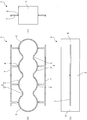
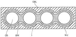
- FIG. 1 It is a perspective view which shows the outline of an example of the spacer for water jackets manufactured by embodiment of this invention. It is explanatory drawing which shows the outline of the spacer for water jackets manufactured by embodiment of this invention, (a) is a top view, (b) is a front view, (c) is a side view. It is explanatory drawing which shows an example of the internal combustion engine with which the spacer for water jackets manufactured by embodiment of this invention is assembled
- the spacer 1 manufactured according to the present embodiment has a cylinder block CBL and a cylinder head (not shown), and four cylinder bores CB arranged in series are formed in the cylinder block CBL. It is assembled inside a water jacket WJ provided in a water-cooled in-line 4-cylinder engine for automobiles.
- FIG. 3 is an explanatory view showing an example of a water-cooled internal combustion engine to which the spacer 1 is assembled. In the figure, the spacer 1 is indicated by a two-dot chain line.
- the bore walls BW of a plurality (four in the illustrated example) of the cylinder bores CB are formed so as to be continuously integrated in a constricted shape between adjacent cylinder bores CB.
- a water jacket WJ as a cooling water circulation path is formed around the wall BW.
- the spacer 1 has a shape that can be inserted into the water jacket WJ, and usually has a constricted portion having a constricted shape along a bore wall BW that is constricted between adjacent cylinder bores CB.
- the specific shape is not particularly limited, although a plurality of (four in the illustrated example) cylindrical portions are integrally formed in a hollow shape.
- the spacer 1 is appropriately designed so that the temperature distribution of the bore wall BW can be optimized by controlling the flow of cooling water flowing in the water jacket WJ by being inserted and assembled into the water jacket WJ. can do.
- a shape that can be partially inserted into the water jacket WJ can also be used.
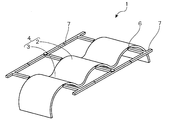
- FIG. 1 and FIG. 2 show a schematic shape of the spacer 1 manufactured in the present embodiment.
- the spacer 1 has a shape in which a plurality of arc-shaped peripheral surface portions 2 connected to each other via a constricted portion 3 face each other and are connected to an arc-shaped end surface portion 5 at both longitudinal ends.
- a plurality of gates 6 serving as inflow ports for the resin material filled in the cavity are arranged along the longitudinal direction at a position corresponding to the outer peripheral surface of the side wall portion 4. It is molded by injection molding a predetermined resin material using an injection mold for which a resin flow path is designed.
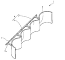
- the runner 7 connected to the gate 6 is cooled in a comb-like state, and then the runner 7 is removed. To do.
- the runner 7 which has been connected to the outer peripheral surface of the side wall portion 4 of the spacer 1 in a comb-like shape suppresses deformation of the spacer 1 in a softened state immediately after ejection, and the spacer 1 is cooled.
- the shape of the spacer 1 can be maintained until it solidifies.
- the runner 7 connected to the side wall portion 4 of the spacer 1 in a comb-tooth shape is cut off after the spacer 1 is sufficiently solidified and there is no risk of deformation.
- FIG. 4 is a schematic diagram illustrating an example of a mold used in the present embodiment.
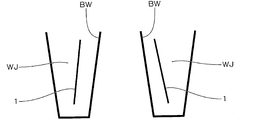
- FIG. 5 is a schematic diagram showing an example in which the spacer 1 manufactured according to the present embodiment is assembled to the water jacket WJ.
- the burrs remaining in the spacer 1 after the gate cut and the burrs formed along the parting line PL are not formed on the inner peripheral side of the spacer 1, the management thereof is facilitated. Furthermore, since the gate cutting process is also performed on the outer peripheral surface side of the spacer 1, it is easy to handle a tool for that purpose.
- the spacer 1 in the cooling process after molding is manufactured with high productivity without being restricted by design due to a draft. Can be prevented from being deformed.
- FIG. 6 Another example of the spacer 1 manufactured according to the present embodiment is shown in FIG. 6.
- the branch portion of the runner 7 is used.
- a fire-like reinforcing portion 7a can be formed.
- the gates 6 are arranged at positions corresponding to the center in the height direction of the side wall 4 of the spacer 1. In this way, the deformation of the spacer 1 in the cooling step after molding can be more effectively prevented.
- the height of the side wall portion 4 on which the gates 6 are arranged is arranged. The position of the direction is not limited to this.
- the gates 6 are arranged at positions corresponding to the arcuate peripheral surface portion 2 of the side wall portion 4. By doing so, the resin pressure in the vicinity of the exit of the gate 6 is hardly lowered and filling failure can be suppressed. However, on the other hand, there is a concern that flow defects such as welds may occur in the constricted portion 3. Is done. For this reason, when it is necessary to avoid a flow failure such as a weld in the constricted portion 3, the gates 6 may be arranged at positions corresponding to the constricted portion 3 of the side wall portion 4.
- the position at which the gates 6 are arranged can be appropriately designed from the viewpoint of moldability in consideration of the flow of the resin and the like, and the position corresponding to the arcuate peripheral surface portion 2 of the side wall portion 4 as necessary.
- the gate 6 may be disposed at both the position corresponding to the constricted portion 3 of the side wall portion 4.
- the resin material is not particularly limited, and examples thereof include polypropylene, polyamide, polyphenylsulfone, and the like, but a resin material excellent in heat resistance, water resistance, antifreeze liquid resistance, wear resistance, and the like is used. It can be selected appropriately.
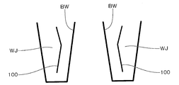
- the spacer 1 can be formed into a shape that can be partially inserted into the water jacket WJ as described above.
- the spacer 1 is formed on a part of the water jacket WJ on the side where the cooling water flows.
- the spacer 1 is connected to the plurality of arc-shaped peripheral surface portions 2 via the constricted portions 3. If it is the shape which has the side wall part 4 (refer FIG.7 and FIG.8), the deformation
- the water jacket spacer used in the water-cooled in-line four-cylinder engine for automobiles has been described as an example, but the present invention is also applicable to other in-line multi-cylinder engines such as an in-line three-cylinder engine. You can also. Further, the present invention can be applied not only to an in-line engine but also to a V-type engine and a horizontally opposed engine, and can be widely applied to a water-cooled internal combustion engine having a water jacket.
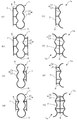
- FIG. 9 (a) to 9 (d) show a modified example in which the present invention is applied to an in-line three-cylinder engine.
- the spacer 1 has a side wall portion in which three arc-shaped peripheral surface portions 2 are connected via a constricted portion 3.
- FIG. 4 is arranged to face each other, and has a shape connected to the arcuate end surface portion 5 at both ends in the longitudinal direction.
- FIG. 9A gates are arranged along the longitudinal direction at a position corresponding to the arcuate peripheral surface portion 2 of one side wall portion 4 arranged to face the runner 7 on one side wall portion 4.
- FIG. 9B shows an example in which the gates 6 are arranged along the longitudinal direction at positions corresponding to the arcuate peripheral surface portions 2 of both side wall portions 4 arranged to face each other.
- runners 7 are connected to both side wall portions 4 in a comb-teeth shape.
- FIG. 9C shows the arrangement of the gates along the longitudinal direction at positions corresponding to the constricted portions 3 of the one side wall portion 4 arranged opposite to each other.
- FIG. 9D shows an example in which the gates 6 are arranged along the longitudinal direction at positions corresponding to the constricted portions 3 of both the side wall portions 4 arranged opposite to each other.
- a runner 7 is connected to the side wall portion 4 in a comb shape.
- FIGS. 9E to 9H show an example in which a divided molded body 1a obtained by dividing the spacer 1 into two along the longitudinal direction is formed, and the two divided molded bodies 1a are combined to form the spacer 1.
- FIG. 9E to 9H show an example in which a divided molded body 1a obtained by dividing the spacer 1 into two along the longitudinal direction is formed, and the two divided molded bodies 1a are combined to form the spacer 1.
- FIG. 9 (e) shows an example in which the runners 7 are connected in a comb shape by arranging gates along the longitudinal direction at positions corresponding to the outer peripheral surface of the arc-shaped peripheral surface portion 2 of the side wall portion 4 of the divided molded body 1a.
- two divided molded bodies 1a can be taken.
- FIG. 9G shows that the runners 7 are arranged by arranging gates along the longitudinal direction at positions corresponding to the outer circumferential surfaces of the arcuate circumferential surface portion 2 and the constricted portion 3 on both ends of the side wall portion 4 of the divided molded body 1a.
- two divided molded bodies 1a can be taken.
- the spacer 1 is formed by combining the divided molded bodies 1a divided in the longitudinal direction, but the spacer 1 is divided at an arbitrary portion.
- a plurality of divided molded bodies can be combined.
- the present invention is applied to mold the divided molded body. Deformation in the subsequent cooling step can be suppressed.
- the spacer 1 has a shape that can be partially inserted into the water jacket WJ, by applying the present invention in the same manner as the example shown in FIGS. 9 (e) to 9 (h), Deformation in the cooling process can be suppressed.
- the spacer 1 has a shape having a side wall portion 4 in which a plurality of arc-shaped peripheral surface portions 2 are connected via a constricted portion 3. If there is no portion that is undercut when the mold is opened, for example, an injection mold having a mold structure in which the outer peripheral side of the side wall portion 4 is molded by a fixed mold and the inner peripheral side of the side wall portion 4 is molded by a movable mold.
- the spacer 1 can be molded by the molding die.
- the gates 6 may be arranged at positions corresponding to both end edges of the spacer 1. Even in this case, it is not necessary to provide a draft on the inner peripheral surface of the spacer 1. .
- the restriction due to the draft angle when designing the spacer 1 so that the temperature distribution of the bore wall BW can be optimized is eased, and burrs remaining on the spacer 1 after the gate cut, Since the burrs formed along the contour lines are not formed on the inner peripheral side of the spacer 1, the management thereof becomes easy. Furthermore, it becomes easy to handle a tool for the gate cutting process.
Landscapes
- Engineering & Computer Science (AREA)
- Manufacturing & Machinery (AREA)
- Mechanical Engineering (AREA)
- Moulds For Moulding Plastics Or The Like (AREA)
- Cylinder Crankcases Of Internal Combustion Engines (AREA)
- Injection Moulding Of Plastics Or The Like (AREA)
Abstract
複数の円弧状周面部(2)がくびれ部(3)を介して連接した側壁部(4)の外周面に相当する位置に、長手方向に沿って複数のゲート(6)が配列するように樹脂流路が設計された射出成形型を用いてスペーサ(1)を射出成形し、型開きしてエジェクトした後も、ゲート(6)に連なるランナ(7)を残した状態としたまま冷却し、しかる後に、ランナ(7)を切除する。これにより、ウォータジャケットの内部に組み付けられて、冷却水の流れを制御するウォータジャケット用スペーサを射出成形によって製造するにあたり、抜き勾配による設計上の制約を受けたりせずに生産性よく製造しながらも、成形後の冷却工程における変形を防止する。
Description
本発明は、水冷式の内燃機関が備えるウォータジャケットの内部に組み付けられるウォータジャケット用スペーサの製造方法に関する。
自動車用水冷式エンジンなどの水冷式の内燃機関にあっては、シリンダボアのボア壁の周囲に、冷却水循環路としてのウォータジャケットが形成されており、通常、かかるウォータジャケットの内部に、スペーサ(ウォータジャケット用スペーサ)を挿入して組み付けることによって、冷却水の流れを制御している。
このようなウォータジャケット用スペーサは、一般には、所定の樹脂材料を用いて射出成形によって製造されるところ、特許文献1には、形状矯正用の治具を用いることなく、成形後の冷却工程における変形を防止するために、ウォータジャケット内に挿入し得る筒状のスペーサ本体部の相対向する部分どうしを架橋部で連結して、成形後に形状保持させた後に、当該架橋部を切除する方法が提案されている。
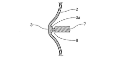
しかしながら、特許文献1の方法にあっては、溶融樹脂をゲートに導くランナを架橋部としているが、この場合の型構造は、図10に示すように、スペーサ100の内周面を形成する型駒を分割型として、そのパーティングラインPLにゲートGを配置することになる。
そうすると、型開きを考慮した抜き勾配を、スペーサ100の内周面にパーティングラインPLを境に異なる傾斜で、図中矢印で示す型開き方向に沿って設ける必要がある。このため、図11に示すように、スペーサ100をウォータジャケットWJの内部に組み付けたときに、ウォータジャケットWJの壁面の傾斜に沿ってスペーサ100の内周面を対向させることができなくなってしまう。そうすると、ボア壁BWの上部とスペーサ100との間の空隙が広くなるなどして、冷却水が滞留して冷却効率が低下してしまう虞があるので、これを考慮してスペーサの形状を設計しなければならないなど、抜き勾配による設計上の制約があった。
また、ウォータジャケットの壁面とスペーサとの隙間は、一般には、ボア壁の保温のために、ウォータジャケット内に組み付けたときにスペーサの外周側に形成される隙間よりも、スペーサの内周側に形成される隙間を狭くなるようにすることが多い。このため、特許文献1の方法では、スペーサ本体の内周面にゲートカット後に残るバリや、パーティングラインに沿って形成されるバリの管理が厳しくなるという問題もあった。
さらに、スペーサ本体部の相対向する部分どうしを連結する架橋部を切除する際には、そのための工具をスペーサ本体部の内側に挿通させて作業しなければならず、スペーサ本体部と干渉しないように工具の取り回しを工夫する必要もあった。
本発明は、上記事情に鑑みてなされたものであり、ウォータジャケットの内部に組み付けられて、冷却水の流れを制御するウォータジャケット用スペーサを射出成形によって製造するにあたり、抜き勾配による設計上の制約を受けたりせずに生産性よく製造しながらも、成形後の冷却工程における変形を防止することができるウォータジャケット用スペーサの製造方法の提供を目的とする。
本発明に係るウォータジャケット用スペーサの製造方法は、水冷式の内燃機関が備えるウォータジャケットの内部に組み付けて冷却水の流れを制御するウォータジャケット用スペーサの製造方法であって、前記ウォータジャケット用スペーサが、複数の円弧状周面部がくびれ部を介して連接した側壁部を有し、前記側壁部の外周面に相当する位置に、長手方向に沿って複数のゲートが配列するように樹脂流路が設計された射出成形型を用いて、所定の樹脂材料を射出成形し、型開きしてエジェクトした後も、前記ゲートに連なるランナを残した状態としたまま冷却し、しかる後に、前記ランナを切除する方法としてある。
本発明によれば、ウォータジャケット用スペーサを射出成形によって製造するにあたり、抜き勾配による設計上の制約を受けたりせずに生産性よく製造しながらも、成形後の冷却工程におけるウォータジャケット用スペーサの変形を防止することができる。
以下、本発明に係るウォータジャケット用スペーサの製造方法の実施形態について、図面を参照しつつ説明する。
本実施形態により製造されるスペーサ1は、図3に示すように、シリンダブロックCBLと、図示しないシリンダヘッドとを有し、シリンダブロックCBLに、直列に配置された四つのシリンダボアCBが形成された自動車用の水冷式直列4気筒エンジンが備えるウォータジャケットWJの内部に組み付けられる。
なお、図3は、スペーサ1が組み付けられる水冷式の内燃機関の一例を示す説明図であり、図中、スペーサ1を二点鎖線で示している。
なお、図3は、スペーサ1が組み付けられる水冷式の内燃機関の一例を示す説明図であり、図中、スペーサ1を二点鎖線で示している。
シリンダブロックCBLには、複数(図示する例では四つ)のシリンダボアCBのボア壁BWが、隣接するシリンダボアCBの間でくびれた形状で連続して一体となるように形成されるとともに、かかるボア壁BWの周囲に、冷却水循環路としてのウォータジャケットWJが形成されている。
スペーサ1は、ウォータジャケットWJの内部に挿入可能な形状とされ、隣接するシリンダボアCBの間でくびれた形状とされたボア壁BWに沿うように、通常は、同様のくびれた形状を有するくびれ部を介して、複数(図示する例では四つ)の円筒部が中空状に一体に連なった形状を有するが、その具体的な形状は特に限定されない。スペーサ1は、ウォータジャケットWJの内部に挿入して組み付けることによって、ウォータジャケットWJ内を流動する冷却水の流れを制御して、ボア壁BWの温度分布を最適化することができるように適宜設計することができる。例えば、ウォータジャケットWJの全周にわたって挿入可能な形状の他に、ウォータジャケットWJの内部に部分的に挿入可能な形状とすることもできる。
本実施形態において製造されるスペーサ1の概略形状を図1及び図2に示す。スペーサ1は、複数の円弧状周面部2がくびれ部3を介して連接した側壁部4が対向して配置され、長手方向両端で円弧状端面部5に接続された形状を有している。このような形状とされたスペーサ1は、側壁部4の外周面に相当する位置に、キャビティ内に充填される樹脂材料の流入口となるゲート6が、長手方向に沿って複数配列するように樹脂流路が設計された射出成形型を用いて、所定の樹脂材料を射出成形することによって成形される。
そして、射出成形型を型開きして、成形されたスペーサ1をエジェクトした後も、ゲート6に連なるランナ7を櫛歯状に残した状態としたまま冷却し、しかる後に、当該ランナ7を切除する。
このようにすることで、スペーサ1の側壁部4の外周面に、櫛歯状に接続したままのランナ7が、エジェクト直後の軟化状態にあるスペーサ1の変形を抑制し、スペーサ1が冷却されて固化していくまでの間のスペーサ1の形状保持が可能となる。スペーサ1の側壁部4に櫛歯状に接続したランナ7は、スペーサ1が十分に固化して変形の虞がなくなってから切除する。
このようにすることで、スペーサ1の側壁部4の外周面に、櫛歯状に接続したままのランナ7が、エジェクト直後の軟化状態にあるスペーサ1の変形を抑制し、スペーサ1が冷却されて固化していくまでの間のスペーサ1の形状保持が可能となる。スペーサ1の側壁部4に櫛歯状に接続したランナ7は、スペーサ1が十分に固化して変形の虞がなくなってから切除する。
このように、本実施形態にあっては、射出成形時の樹脂流路に形成されるランナ7を利用して、成形後のスペーサ1の形状を保持するが、側壁部の外周面に相当する位置にゲート6を配列させるので、図4に示すように、スペーサ1の内周面を形成する型駒を分割型にする必要がない。このため、スペーサ1の内周面の抜き勾配を型開き方向に沿って一定の勾配とすることができる。
なお、図4は、本実施形態で用いる成形型の一例を示す模式図である。
なお、図4は、本実施形態で用いる成形型の一例を示す模式図である。
したがって、スペーサ1をウォータジャケットWJに組み付けたときに、図5に示すように、ウォータジャケットWJの壁面の傾斜に沿ってスペーサ1の内周面を対向させることができるので、冷却水が滞留することなく、冷却水の流れを支障なく制御することができ、ボア壁BWの温度分布を最適化することができるようにスペーサ1を設計する際の抜き勾配による制約が緩和される。
なお、図5は、本実施形態により製造されるスペーサ1をウォータジャケットWJに組み付けた例を示す模式図である。
なお、図5は、本実施形態により製造されるスペーサ1をウォータジャケットWJに組み付けた例を示す模式図である。
また、ゲートカット後にスペーサ1に残るバリや、パーティングラインPLに沿って形成されるバリがスペーサ1の内周側に形成されることがないので、その管理も容易になる。
さらに、ゲートカット処理もスペーサ1の外周面側で行うので、そのための工具の取り回しも容易になる。
さらに、ゲートカット処理もスペーサ1の外周面側で行うので、そのための工具の取り回しも容易になる。
このように、本実施形態によれば、スペーサ1を射出成形によって製造するにあたり、抜き勾配による設計上の制約を受けたりせずに生産性よく製造しながらも、成形後の冷却工程におけるスペーサ1の変形を防止することができる。
本実施形態により製造されるスペーサ1の他の例を図6に示すが、スペーサ1の側壁部4に櫛歯状に接続したランナ7によってスペーサ1の形状を保持するにあたり、ランナ7の分岐部には、火打ち状の補強部7aを形成することもできる。
本実施形態により製造されるスペーサ1の他の例を図6に示すが、スペーサ1の側壁部4に櫛歯状に接続したランナ7によってスペーサ1の形状を保持するにあたり、ランナ7の分岐部には、火打ち状の補強部7aを形成することもできる。
また、図1及び図2に示す例では、スペーサ1の側壁部4の高さ方向中央に相当する位置にゲート6を配列させている。このようにすることで、成形後の冷却工程におけるスペーサ1の変形をより有効に防止することができるが、スペーサ1の形状保持が可能であれば、ゲート6を配列させる側壁部4の高さ方向の位置は、これに限定されない。
また、図1及び図2に示す例では、側壁部4の円弧状周面部2に相当する位置にゲート6を配列させている。このようにすることで、ゲート6の出口付近での樹脂圧の低下が起こり難く充填不良を抑制することができるが、その反面、くびれ部3にウェルドなどの流動不良が生じてしまうことが懸念される。このため、ウェルドなどの流動不良がくびれ部3に生じるのを避ける必要がある場合は、側壁部4のくびれ部3に相当する位置にゲート6を配列させてもよい。いずれの位置にゲート6を配列させるかは、樹脂の流動などを考慮して成形性の観点から適宜設計することができ、必要に応じて、側壁部4の円弧状周面部2に相当する位置と、側壁部4のくびれ部3に相当する位置の両方にゲート6を配置させてもよい。
本実施形態において、樹脂材料としては特に限定されず、例えば、ポリプロピレン、ポリアミド、ポリフェニルサルフォンなどが挙げられるが、耐熱性、耐水性、耐不凍液性、耐摩耗性などに優れた樹脂材料を適宜選択することができる。
また、スペーサ1は、ウォータジャケットWJの内部に部分的に挿入可能な形状とすることができるのは前述した通りであり、例えば、ウォータジャケットWJ内に冷却水が流入する側の一部にスペーサ1を組み付けて、ウォータジャケットWJから冷却水が排出される側にはスペーサ1を組み付けないような場合などには、スペーサ1が、複数の円弧状周面部2がくびれ部3を介して連接した側壁部4を有する形状であれば(図7及び図8参照)、本発明を適用して、かかる形状のスペーサ1の成形後の冷却工程における変形を抑止することができる。
以上、本発明について、好ましい実施形態を示して説明したが、本発明は、前述した実施形態に限定されるものではなく、本発明の範囲で種々の変更実施が可能であることは言うまでもない。
例えば、前述した実施形態では、自動車用の水冷式直列4気筒エンジンに利用されるウォータジャケット用スペーサを例に挙げて説明したが、直列3気筒エンジンなどの他の直列多気筒エンジンにも適用することもできる。また、直列エンジンに限らず、V型エンジン、水平対向エンジンにも適用することができ、ウォータジャケットを備えた水冷式の内燃機関に広く適用可能である。
[変形例]
さらに、本発明の変形例について、図9を参照しつつ説明する。
さらに、本発明の変形例について、図9を参照しつつ説明する。
図9(a)~(d)は、本発明を直列3気筒エンジンに適用した変形例を示しており、スペーサ1は、三つの円弧状周面部2がくびれ部3を介して連接した側壁部4が対向して配置され、長手方向両端で円弧状端面部5に接続された形状を有している。
図9(a)は、対向して配置された一方の側壁部4の円弧状周面部2に相当する位置に、長手方向に沿ってゲートを配列して、一方の側壁部4にランナ7を櫛歯状に接続した例であり、図9(b)は、対向して配置された両方の側壁部4の円弧状周面部2に相当する位置に、長手方向に沿ってゲート6を配列して、両方の側壁部4にランナ7を櫛歯状に接続した例である。
図9(c)は、対向して配置された一方の側壁部4のくびれ部3に相当する位置に、長手方向に沿ってゲートを配列して、一方の側壁部4にランナ7を櫛歯状に接続した例であり、図9(d)は、対向して配置された両方の側壁部4のくびれ部3に相当する位置に、長手方向に沿ってゲート6を配列して、両方の側壁部4にランナ7を櫛歯状に接続した例である。
くびれ部3に相当する位置にゲートを配列する場合には、図10に示すように、くびれ部3の側壁部内周側を平面とし、側壁部外周側に台座3aを介してゲート6が接続されるようにすることで、ゲートカット処理を容易にすることができる。
くびれ部3に相当する位置にゲートを配列する場合には、図10に示すように、くびれ部3の側壁部内周側を平面とし、側壁部外周側に台座3aを介してゲート6が接続されるようにすることで、ゲートカット処理を容易にすることができる。
また、図9(e)~(h)は、スペーサ1を長手方向に沿って二分された分割成形体1aを成形して、二つの分割成形体1aを組み合わせてスペーサ1とする例である。
図9(e)は、分割成形体1aの側壁部4の円弧状周面部2の外周面に相当する位置に、長手方向に沿ってゲートを配列してランナ7を櫛歯状に接続した例であり、かかる例において、図9(f)に示すように、分割成形体1aを二個取りすることもできる。
図9(g)は、分割成形体1aの側壁部4の両端側の円弧状周面部2とくびれ部3の外周面に相当する位置に、長手方向に沿ってゲートを配列してランナ7を櫛歯状に接続した例であり、かかる例において、図9(h)に示すように、分割成形体1aを二個取りすることもできる。
また、図9(e)~(h)に示す例において、スペーサ1は、その長手方向に沿って二分された分割成形体1aを組み合わせてなるが、スペーサ1は、任意の部分で分割された複数の分割成形体を組み合わせるようにすることもできる。この場合、少なくとも一つの分割成形体が、複数の円弧状周面部2がくびれ部3を介して連接した側壁部4を有する形状であれば、本発明を適用して、当該分割成形体の成形後の冷却工程における変形を抑止することができる。
さらに、スペーサ1をウォータジャケットWJの内部に部分的に挿入可能な形状とする場合も、図9(e)~(h)に示す例と同様にして本発明を適用することによって、成形後の冷却工程における変形を抑止することができる。
さらに、スペーサ1をウォータジャケットWJの内部に部分的に挿入可能な形状とする場合も、図9(e)~(h)に示す例と同様にして本発明を適用することによって、成形後の冷却工程における変形を抑止することができる。
また、図9(e)~(h)に示すような分割成形体1aのように、スペーサ1が、複数の円弧状周面部2がくびれ部3を介して連接した側壁部4を有する形状であって、型開きに際してアンダーカットとなるような部位がなければ、例えば、側壁部4の外周側を固定型により成形し、側壁部4の内周側を可動型により成形する型構造とした射出成形型により、スペーサ1を成形することができる。この場合、ゲート6は、図11に示すように、スペーサ1の両端縁に相当する位置に配列させればよく、このようにしても、スペーサ1の内周面に抜き勾配を設ける必要がなくなる。
したがって、このような態様によっても、ボア壁BWの温度分布を最適化することができるようにスペーサ1を設計する際の抜き勾配による制約が緩和され、ゲートカット後にスペーサ1に残るバリや、パーティングラインに沿って形成されるバリがスペーサ1の内周側に形成されることもないので、その管理も容易になる。さらに、ゲートカット処理に際しても、そのための工具の取り回しも容易になる。
この明細書に記載の文献及び本願のパリ優先の基礎となる日本出願明細書の内容を全てここに援用する。
1 スペーサ
1a 分割成形体
2 円弧状周面部
3 くびれ部
4 側壁部
5 円弧状端面部
6 ゲート
7 ランナ
7a 補強部
WJ ウォータジャケット
1a 分割成形体
2 円弧状周面部
3 くびれ部
4 側壁部
5 円弧状端面部
6 ゲート
7 ランナ
7a 補強部
WJ ウォータジャケット
Claims (8)
- 水冷式の内燃機関が備えるウォータジャケットの内部に組み付けて冷却水の流れを制御するウォータジャケット用スペーサの製造方法であって、
前記ウォータジャケット用スペーサが、複数の円弧状周面部がくびれ部を介して連接した側壁部を有し、
前記側壁部の外周面に相当する位置に、長手方向に沿って複数のゲートが配列するように樹脂流路が設計された射出成形型を用いて、所定の樹脂材料を射出成形し、
型開きしてエジェクトした後も、前記ゲートに連なるランナを残した状態としたまま冷却し、しかる後に、前記ランナを切除することを特徴とするウォータジャケット用スペーサの製造方法。 - 前記ランナが、前記側壁部に櫛歯状に接続した請求項1に記載のウォータジャケット用スペーサの製造方法。
- 前記ランナの分岐部に、火打ち状の補強部を設けた請求項2に記載のウォータジャケット用スペーサの製造方法。
- 前記ウォータジャケット用スペーサが、前記側壁部が対向して配置され、長手方向両端で円弧状端面部に接続された形状である請求項1~3のいずれか一項に記載のウォータジャケット用スペーサの製造方法。
- 前記ウォータジャケット用スペーサが、複数の円弧状周面部がくびれ部を介して連接した側壁部を有する形状の分割成形体を含む複数の分割成形体を成形して、これらの分割成形体を組み合わせてなる請求項4に記載のウォータジャケット用スペーサの製造方法。
- 前記ウォータジャケット用スペーサが、前記ウォータジャケット用スペーサを長手方向に沿って二分された分割成形体を成形して、当該二つの分割成形体を組み合わせてなる請求項5に記載のウォータジャケット用スペーサの製造方法。
- 前記円弧状周面部に相当する位置に前記ゲートを配置した請求項1~6のいずれか一項に記載のウォータジャケット用スペーサの製造方法。
- 前記くびれ部に相当する位置に前記ゲートを配置した請求項1~7のいずれか一項に記載のウォータジャケット用スペーサの製造方法。
Priority Applications (4)
| Application Number | Priority Date | Filing Date | Title |
|---|---|---|---|
| CN201580022996.9A CN106460718B (zh) | 2014-04-30 | 2015-04-28 | 水套用间隔件的制造方法 |
| US15/307,156 US10513065B2 (en) | 2014-04-30 | 2015-04-28 | Method for producing water jacket spacer |
| EP15785220.3A EP3139024B1 (en) | 2014-04-30 | 2015-04-28 | Method for producing water jacket spacer |
| US16/684,657 US20200078994A1 (en) | 2014-04-30 | 2019-11-15 | Method for producing water jacket spacer |
Applications Claiming Priority (4)
| Application Number | Priority Date | Filing Date | Title |
|---|---|---|---|
| JP2014093697 | 2014-04-30 | ||
| JP2014-093697 | 2014-04-30 | ||
| JP2015-006451 | 2015-01-16 | ||
| JP2015006451A JP6362548B2 (ja) | 2014-04-30 | 2015-01-16 | ウォータジャケット用スペーサの製造方法 |
Related Child Applications (2)
| Application Number | Title | Priority Date | Filing Date |
|---|---|---|---|
| US15/307,156 A-371-Of-International US10513065B2 (en) | 2014-04-30 | 2015-04-28 | Method for producing water jacket spacer |
| US16/684,657 Continuation US20200078994A1 (en) | 2014-04-30 | 2019-11-15 | Method for producing water jacket spacer |
Publications (1)
| Publication Number | Publication Date |
|---|---|
| WO2015166660A1 true WO2015166660A1 (ja) | 2015-11-05 |
Family
ID=54358403
Family Applications (1)
| Application Number | Title | Priority Date | Filing Date |
|---|---|---|---|
| PCT/JP2015/002275 WO2015166660A1 (ja) | 2014-04-30 | 2015-04-28 | ウォータジャケット用スペーサの製造方法 |
Country Status (5)
| Country | Link |
|---|---|
| US (2) | US10513065B2 (ja) |
| EP (1) | EP3139024B1 (ja) |
| JP (1) | JP6362548B2 (ja) |
| CN (1) | CN106460718B (ja) |
| WO (1) | WO2015166660A1 (ja) |
Cited By (1)
| Publication number | Priority date | Publication date | Assignee | Title |
|---|---|---|---|---|
| WO2018097057A1 (ja) * | 2016-11-22 | 2018-05-31 | 内山工業株式会社 | スペーサ |
Families Citing this family (9)
| Publication number | Priority date | Publication date | Assignee | Title |
|---|---|---|---|---|
| WO2016114333A1 (ja) * | 2015-01-16 | 2016-07-21 | ニチアス株式会社 | ウォータジャケット用スペーサの製造方法 |
| JP6395697B2 (ja) | 2015-01-16 | 2018-09-26 | ニチアス株式会社 | ウォータージャケットスペーサの製造方法 |
| WO2016114332A1 (ja) * | 2015-01-16 | 2016-07-21 | ニチアス株式会社 | ウォータージャケットスペーサの製造方法 |
| JP6745520B2 (ja) * | 2016-05-10 | 2020-08-26 | 内山工業株式会社 | スペーサの製造方法 |
| CN108131213B (zh) * | 2018-01-24 | 2019-11-22 | 东风柳州汽车有限公司 | 四冲程水冷汽油发动机冷却水套 |
| JP7129203B2 (ja) | 2018-04-24 | 2022-09-01 | キヤノン株式会社 | ポリゴンミラー、偏向器、光走査装置、および画像形成装置 |
| JP7201990B2 (ja) * | 2018-10-25 | 2023-01-11 | 内山工業株式会社 | スペーサ及びその製造方法 |
| JP7445951B2 (ja) * | 2019-01-10 | 2024-03-08 | 内山工業株式会社 | スペーサ |
| JP7464245B2 (ja) * | 2019-01-29 | 2024-04-09 | 内山工業株式会社 | スペーサ及びその製造方法 |
Citations (2)
| Publication number | Priority date | Publication date | Assignee | Title |
|---|---|---|---|---|
| JP2005105878A (ja) * | 2003-09-29 | 2005-04-21 | Uchiyama Mfg Corp | ウォータジャケット用スペーサの製造方法 |
| JP2012036742A (ja) * | 2010-08-03 | 2012-02-23 | Honda Motor Co Ltd | スペーサ |
Family Cites Families (10)
| Publication number | Priority date | Publication date | Assignee | Title |
|---|---|---|---|---|
| GB8428640D0 (en) | 1984-11-13 | 1984-12-19 | Avon Ind Polymers | Valve for respirator |
| JPH06173675A (ja) * | 1992-12-04 | 1994-06-21 | Kubota Corp | 多気筒水冷エンジンの冷却装置 |
| JP4017584B2 (ja) * | 2003-10-17 | 2007-12-05 | トヨタ自動車株式会社 | シリンダブロックの冷却構造 |
| US20060180153A1 (en) | 2005-01-27 | 2006-08-17 | Bernie Schaub | Assembly for mounting a device to a mask |
| JP4845620B2 (ja) * | 2006-07-21 | 2011-12-28 | トヨタ自動車株式会社 | 内燃機関冷却用熱媒体流路区画部材、内燃機関冷却構造及び内燃機関冷却構造形成方法 |
| JP4851258B2 (ja) | 2006-07-31 | 2012-01-11 | トヨタ自動車株式会社 | 内燃機関冷却用熱媒体流路区画部材、内燃機関冷却機構及び内燃機関冷却機構形成方法 |
| JP2010005819A (ja) * | 2008-06-24 | 2010-01-14 | Suzuki Motor Corp | 成形用金型及び成形品の製造方法 |
| US8955516B2 (en) | 2009-04-08 | 2015-02-17 | Scott Technologies, Inc. | Face seals for respirators and method of manufacturing respirators |
| CN102072001B (zh) | 2009-11-19 | 2013-06-19 | 本田技研工业株式会社 | 内燃机的冷却结构 |
| JP5610290B2 (ja) * | 2010-11-29 | 2014-10-22 | 内山工業株式会社 | ウォータジャケットスペーサ |
-
2015
- 2015-01-16 JP JP2015006451A patent/JP6362548B2/ja active Active
- 2015-04-28 EP EP15785220.3A patent/EP3139024B1/en active Active
- 2015-04-28 WO PCT/JP2015/002275 patent/WO2015166660A1/ja active Application Filing
- 2015-04-28 US US15/307,156 patent/US10513065B2/en not_active Expired - Fee Related
- 2015-04-28 CN CN201580022996.9A patent/CN106460718B/zh not_active Expired - Fee Related
-
2019
- 2019-11-15 US US16/684,657 patent/US20200078994A1/en not_active Abandoned
Patent Citations (2)
| Publication number | Priority date | Publication date | Assignee | Title |
|---|---|---|---|---|
| JP2005105878A (ja) * | 2003-09-29 | 2005-04-21 | Uchiyama Mfg Corp | ウォータジャケット用スペーサの製造方法 |
| JP2012036742A (ja) * | 2010-08-03 | 2012-02-23 | Honda Motor Co Ltd | スペーサ |
Cited By (2)
| Publication number | Priority date | Publication date | Assignee | Title |
|---|---|---|---|---|
| WO2018097057A1 (ja) * | 2016-11-22 | 2018-05-31 | 内山工業株式会社 | スペーサ |
| JP2018084167A (ja) * | 2016-11-22 | 2018-05-31 | 内山工業株式会社 | スペーサ |
Also Published As
| Publication number | Publication date |
|---|---|
| CN106460718B (zh) | 2019-07-23 |
| EP3139024A4 (en) | 2017-11-01 |
| US20200078994A1 (en) | 2020-03-12 |
| EP3139024A1 (en) | 2017-03-08 |
| JP2015222071A (ja) | 2015-12-10 |
| EP3139024B1 (en) | 2019-08-21 |
| US20170043513A1 (en) | 2017-02-16 |
| US10513065B2 (en) | 2019-12-24 |
| JP6362548B2 (ja) | 2018-07-25 |
| CN106460718A (zh) | 2017-02-22 |
Similar Documents
| Publication | Publication Date | Title |
|---|---|---|
| JP6362548B2 (ja) | ウォータジャケット用スペーサの製造方法 | |
| JP5563726B1 (ja) | 重力鋳造用金型 | |
| JP6328094B2 (ja) | ウォータジャケット用スペーサの製造方法 | |
| JP5139926B2 (ja) | バルブゲート構造 | |
| JP4056958B2 (ja) | ウォータジャケット用スペーサの製造方法 | |
| US6298899B1 (en) | Water jacket core | |
| WO2015037506A1 (ja) | スペーサ | |
| JP5442349B2 (ja) | 金型の冷却プレート及びその製造方法 | |
| US8845321B2 (en) | Split thread insert | |
| WO2016114333A1 (ja) | ウォータジャケット用スペーサの製造方法 | |
| JP6745520B2 (ja) | スペーサの製造方法 | |
| JP2013132668A (ja) | シリンダヘッド鋳造用鋳型及びシリンダヘッドの鋳造方法 | |
| CN105828975A (zh) | 用于生产气缸盖的铸造型芯的制造方法 | |
| CN215472729U (zh) | 一种汽车配件生产用模具的冷却镶件 | |
| CN113351830B (zh) | 用于车辆加热器的金属铸造式热交换器壳体的制造方法 | |
| JP2000000634A (ja) | 鋳造用金型におけるガスベント装置 | |
| JPH0711951Y2 (ja) | 射出成形用金型 | |
| WO2016114332A1 (ja) | ウォータージャケットスペーサの製造方法 | |
| KR20030091906A (ko) | 자동차 써모스타트의 하우징 주조용 코어 및 코어금형그리고 하우징 주조용 금형 | |
| JP4583019B2 (ja) | 成形用金型の製造方法 | |
| JPH10109139A (ja) | シリンダスリーブ集合体成形用シェル型 | |
| JPH07180604A (ja) | 金型によるシリンダブロックの鋳造成形方法 | |
| JP2000229334A (ja) | 成形用金型 |
Legal Events
| Date | Code | Title | Description |
|---|---|---|---|
| 121 | Ep: the epo has been informed by wipo that ep was designated in this application |
Ref document number: 15785220 Country of ref document: EP Kind code of ref document: A1 |
|
| REEP | Request for entry into the european phase |
Ref document number: 2015785220 Country of ref document: EP |
|
| WWE | Wipo information: entry into national phase |
Ref document number: 15307156 Country of ref document: US Ref document number: 2015785220 Country of ref document: EP |
|
| NENP | Non-entry into the national phase |
Ref country code: DE |