WO2015159955A1 - デュアルクラッチ装置 - Google Patents
デュアルクラッチ装置 Download PDFInfo
- Publication number
- WO2015159955A1 WO2015159955A1 PCT/JP2015/061733 JP2015061733W WO2015159955A1 WO 2015159955 A1 WO2015159955 A1 WO 2015159955A1 JP 2015061733 W JP2015061733 W JP 2015061733W WO 2015159955 A1 WO2015159955 A1 WO 2015159955A1
- Authority
- WO
- WIPO (PCT)
- Prior art keywords
- hydraulic
- chamber
- clutch
- piston
- hydraulic pressure
- Prior art date
Links
Images


Classifications
-
- F—MECHANICAL ENGINEERING; LIGHTING; HEATING; WEAPONS; BLASTING
- F16—ENGINEERING ELEMENTS AND UNITS; GENERAL MEASURES FOR PRODUCING AND MAINTAINING EFFECTIVE FUNCTIONING OF MACHINES OR INSTALLATIONS; THERMAL INSULATION IN GENERAL
- F16D—COUPLINGS FOR TRANSMITTING ROTATION; CLUTCHES; BRAKES
- F16D48/00—External control of clutches
- F16D48/02—Control by fluid pressure
- F16D48/0206—Control by fluid pressure in a system with a plurality of fluid-actuated clutches
-
- F—MECHANICAL ENGINEERING; LIGHTING; HEATING; WEAPONS; BLASTING
- F16—ENGINEERING ELEMENTS AND UNITS; GENERAL MEASURES FOR PRODUCING AND MAINTAINING EFFECTIVE FUNCTIONING OF MACHINES OR INSTALLATIONS; THERMAL INSULATION IN GENERAL
- F16D—COUPLINGS FOR TRANSMITTING ROTATION; CLUTCHES; BRAKES
- F16D21/00—Systems comprising a plurality of actuated clutches
- F16D21/02—Systems comprising a plurality of actuated clutches for interconnecting three or more shafts or other transmission members in different ways
- F16D21/06—Systems comprising a plurality of actuated clutches for interconnecting three or more shafts or other transmission members in different ways at least two driving shafts or two driven shafts being concentric
-
- F—MECHANICAL ENGINEERING; LIGHTING; HEATING; WEAPONS; BLASTING
- F16—ENGINEERING ELEMENTS AND UNITS; GENERAL MEASURES FOR PRODUCING AND MAINTAINING EFFECTIVE FUNCTIONING OF MACHINES OR INSTALLATIONS; THERMAL INSULATION IN GENERAL
- F16D—COUPLINGS FOR TRANSMITTING ROTATION; CLUTCHES; BRAKES
- F16D25/00—Fluid-actuated clutches
- F16D25/06—Fluid-actuated clutches in which the fluid actuates a piston incorporated in, i.e. rotating with the clutch
- F16D25/062—Fluid-actuated clutches in which the fluid actuates a piston incorporated in, i.e. rotating with the clutch the clutch having friction surfaces
- F16D25/063—Fluid-actuated clutches in which the fluid actuates a piston incorporated in, i.e. rotating with the clutch the clutch having friction surfaces with clutch members exclusively moving axially
- F16D25/0635—Fluid-actuated clutches in which the fluid actuates a piston incorporated in, i.e. rotating with the clutch the clutch having friction surfaces with clutch members exclusively moving axially with flat friction surfaces, e.g. discs
- F16D25/0638—Fluid-actuated clutches in which the fluid actuates a piston incorporated in, i.e. rotating with the clutch the clutch having friction surfaces with clutch members exclusively moving axially with flat friction surfaces, e.g. discs with more than two discs, e.g. multiple lamellae
-
- F—MECHANICAL ENGINEERING; LIGHTING; HEATING; WEAPONS; BLASTING
- F16—ENGINEERING ELEMENTS AND UNITS; GENERAL MEASURES FOR PRODUCING AND MAINTAINING EFFECTIVE FUNCTIONING OF MACHINES OR INSTALLATIONS; THERMAL INSULATION IN GENERAL
- F16D—COUPLINGS FOR TRANSMITTING ROTATION; CLUTCHES; BRAKES
- F16D25/00—Fluid-actuated clutches
- F16D25/10—Clutch systems with a plurality of fluid-actuated clutches
-
- F—MECHANICAL ENGINEERING; LIGHTING; HEATING; WEAPONS; BLASTING
- F16—ENGINEERING ELEMENTS AND UNITS; GENERAL MEASURES FOR PRODUCING AND MAINTAINING EFFECTIVE FUNCTIONING OF MACHINES OR INSTALLATIONS; THERMAL INSULATION IN GENERAL
- F16D—COUPLINGS FOR TRANSMITTING ROTATION; CLUTCHES; BRAKES
- F16D25/00—Fluid-actuated clutches
- F16D25/12—Details not specific to one of the before-mentioned types
- F16D25/14—Fluid pressure control
-
- F—MECHANICAL ENGINEERING; LIGHTING; HEATING; WEAPONS; BLASTING
- F16—ENGINEERING ELEMENTS AND UNITS; GENERAL MEASURES FOR PRODUCING AND MAINTAINING EFFECTIVE FUNCTIONING OF MACHINES OR INSTALLATIONS; THERMAL INSULATION IN GENERAL
- F16D—COUPLINGS FOR TRANSMITTING ROTATION; CLUTCHES; BRAKES
- F16D21/00—Systems comprising a plurality of actuated clutches
- F16D21/02—Systems comprising a plurality of actuated clutches for interconnecting three or more shafts or other transmission members in different ways
- F16D21/06—Systems comprising a plurality of actuated clutches for interconnecting three or more shafts or other transmission members in different ways at least two driving shafts or two driven shafts being concentric
- F16D2021/0653—Hydraulic arrangements for clutch control
-
- F—MECHANICAL ENGINEERING; LIGHTING; HEATING; WEAPONS; BLASTING
- F16—ENGINEERING ELEMENTS AND UNITS; GENERAL MEASURES FOR PRODUCING AND MAINTAINING EFFECTIVE FUNCTIONING OF MACHINES OR INSTALLATIONS; THERMAL INSULATION IN GENERAL
- F16D—COUPLINGS FOR TRANSMITTING ROTATION; CLUTCHES; BRAKES
- F16D21/00—Systems comprising a plurality of actuated clutches
- F16D21/02—Systems comprising a plurality of actuated clutches for interconnecting three or more shafts or other transmission members in different ways
- F16D21/06—Systems comprising a plurality of actuated clutches for interconnecting three or more shafts or other transmission members in different ways at least two driving shafts or two driven shafts being concentric
- F16D2021/0661—Hydraulically actuated multiple lamellae clutches
-
- F—MECHANICAL ENGINEERING; LIGHTING; HEATING; WEAPONS; BLASTING
- F16—ENGINEERING ELEMENTS AND UNITS; GENERAL MEASURES FOR PRODUCING AND MAINTAINING EFFECTIVE FUNCTIONING OF MACHINES OR INSTALLATIONS; THERMAL INSULATION IN GENERAL
- F16D—COUPLINGS FOR TRANSMITTING ROTATION; CLUTCHES; BRAKES
- F16D48/00—External control of clutches
- F16D48/02—Control by fluid pressure
- F16D2048/0257—Hydraulic circuit layouts, i.e. details of hydraulic circuit elements or the arrangement thereof
- F16D2048/0275—Two valves arranged in parallel, e.g. one for coarse and the other for fine control during supplying or draining fluid from the actuation cylinder
-
- F—MECHANICAL ENGINEERING; LIGHTING; HEATING; WEAPONS; BLASTING
- F16—ENGINEERING ELEMENTS AND UNITS; GENERAL MEASURES FOR PRODUCING AND MAINTAINING EFFECTIVE FUNCTIONING OF MACHINES OR INSTALLATIONS; THERMAL INSULATION IN GENERAL
- F16D—COUPLINGS FOR TRANSMITTING ROTATION; CLUTCHES; BRAKES
- F16D2500/00—External control of clutches by electric or electronic means
- F16D2500/50—Problem to be solved by the control system
- F16D2500/51—Relating safety
- F16D2500/5104—Preventing failures
Definitions
- the present invention relates to a dual clutch device.
- one clutch corresponds to an odd-numbered gear train
- the other clutch corresponds to an even-numbered gear train. For this reason, for example, when shifting up from the 2nd speed to the 3rd speed, the even speed clutch is connected and the 2nd speed synchro mechanism is engaged, and the 3rd speed sync mechanism is engaged. Then, by shifting the clutch for the odd-numbered stage while disconnecting the clutch for the even-numbered stage, it is possible to realize a shift that does not cause torque loss.
- each clutch is held in a connected state, which may cause double engagement of the transmission.
- An object of the present invention is to provide a dual clutch device capable of effectively preventing double engagement of a transmission.
- a dual clutch device of the present invention includes a first clutch having a first plate for connecting and disconnecting power transmission from an engine to a transmission first input shaft, and a transmission second input shaft from the engine. And a second clutch having a second plate for connecting / disconnecting power transmission to / from the first clutch, wherein the first plate is pressed by the hydraulic pressure supplied to the first hydraulic chamber to bring the first clutch into contact. And a first piston that is separated from the first plate by a first spring housed in a first hydraulic pressure cancellation chamber and disengages the first clutch, and a second hydraulic pressure that is supplied to the second hydraulic chamber.
- the second clutch is brought into contact by pressing the plate, and the second spring accommodated in the second hydraulic pressure cancel chamber is A second piston that is disengaged from the plate and disengages the second clutch; a first supply line that supplies hydraulic pressure to the first hydraulic chamber and the second hydraulic cancel chamber; and the second hydraulic chamber and the first A second supply line that supplies hydraulic pressure to the hydraulic pressure cancellation chamber, and a first on-off valve that is provided in the first supply line and permits or blocks the supply of hydraulic pressure to the first hydraulic pressure chamber and the second hydraulic pressure cancellation chamber And a second on-off valve provided in the second supply line for permitting or shutting off the supply of hydraulic pressure to the second hydraulic chamber and the first hydraulic cancel chamber.
- the biasing force of the first spring is supplied to the first hydraulic chamber via the first supply line and acts on the first piston, and the second supply to the first hydraulic cancel chamber. It is preferable that the difference is set larger than the difference between the hydraulic pressure supplied through the line and acting on the first piston.
- the urging force of the second spring is supplied to the second hydraulic chamber via the second supply line and acts on the second piston, and the first supply to the second hydraulic cancel chamber. It is preferable to set the difference larger than the difference between the hydraulic pressure supplied via the line and acting on the second piston.
- the dual clutch device 10 includes a first wet clutch C1 and a second wet clutch C2.
- Reference numeral 11 denotes a clutch input shaft to which the power of the engine E is transmitted.
- Reference numeral 12A denotes a transmission first input shaft provided with a transmission gear train that establishes, for example, odd-numbered stages of the transmission T
- reference numeral 12B denotes a transmission second input provided with, for example, a transmission gear train that establishes even-numbered stages. Each shaft is shown.
- the second input shaft 12B is rotatably supported via a bearing 13 in the hollow shaft of the first input shaft 12A.
- the first wet clutch C1 includes a clutch hub 20 that rotates integrally with the clutch input shaft 11, a plurality of first inner plates 21A that are spline-fitted to the clutch hub 20, and a first rotation that rotates integrally with the transmission first input shaft 12A.
- a cylindrical first piston 23 is provided.
- the first piston 23 is slidably accommodated in an annular first piston chamber 24 formed in the clutch hub 20.
- a first hydraulic chamber 25A and a first centrifugal hydraulic pressure cancel chamber 25B are defined by the first piston 23.
- a first return spring 26 that urges the first piston 23 in a direction away from the plates 21A and 21B is accommodated in the first centrifugal hydraulic pressure cancel chamber 25B.
- Reference numeral S denotes a seal member that seals the gap between the first piston 23 and the first piston chamber 24.
- first piston 23 moves in the axial direction and presses the plates 21A and 21B together (first wet clutch C1: contact).
- first wet clutch C1 contact
- the first piston 23 causes the urging force of the first return spring 26 and the first centrifugal hydraulic pressure cancel chamber.
- the pressure state is released by separating from the plates 21A and 21B by the oil pressure in 25B (first wet clutch C1: disengaged).
- the second wet clutch C2 includes a plurality of second outer plates 31A that are spline-fitted to the clutch hub 20, a second clutch drum 32 that rotates integrally with the transmission second input shaft 12B, and a second outer plate 31A.
- a plurality of second inner plates 31B that are alternately arranged and are spline-fitted to the second clutch drum 32, and a cylindrical second piston 33 that can press-contact the plates 31A and 31B in the axial direction are provided.
- the second piston 33 is slidably accommodated in an annular second piston chamber 34 formed in the clutch hub 20.
- a second hydraulic chamber 35 ⁇ / b> A and a second centrifugal hydraulic pressure cancel chamber 35 ⁇ / b> B are defined by the second piston 33.
- a second return spring 36 for energizing the second piston 33 in a direction away from the plates 31A and 31B is accommodated in the second centrifugal hydraulic pressure cancel chamber 35B.
- Reference numeral S denotes a seal member that seals the gap between the second piston 33 and the second piston chamber 34.
- the hydraulic circuit 40 includes a first upstream supply line 43 that connects the oil pan 41 and the first electromagnetic valve 60, and a second upstream supply line that branches from the first upstream supply line 43 and is connected to the second electromagnetic valve 65. 45.
- An oil pump OP that is driven by the power of the engine E is provided in the first upstream supply line 43 upstream of the branch portion.
- a lubricating oil supply line 46 provided with a throttle valve 47 is connected to the second upstream supply line 45.
- a first downstream supply line 50 is connected to the first electromagnetic valve 60.
- the first downstream supply line 50 is branched from the clutch hub 20 into a first hydraulic chamber line 50A and a second cancel chamber line 50B.
- the downstream end of the first hydraulic chamber line 50A is connected to the first hydraulic chamber 25A, and the downstream end of the second cancellation chamber line 50B is connected to the second centrifugal hydraulic cancellation chamber 35B.
- the first electromagnetic valve 60 is closed by the urging force of the spring 61 when not energized (OFF) and opened when energized (ON) by an electronic control unit (not shown).
- first electromagnetic valve 60 When the first electromagnetic valve 60 is open (ON), pressure oil is supplied to the first hydraulic chamber 25A and the second centrifugal hydraulic cancel chamber 35B.
- first electromagnetic valve 60 When the first electromagnetic valve 60 is closed (OFF), no pressure oil is supplied to the first hydraulic chamber 25A and the second centrifugal hydraulic cancel chamber 35B, and the first hydraulic chamber 25A and the second centrifugal hydraulic cancel chamber 35B.
- the pressure oil inside is returned to the oil pan 41 via the oil return line 62.
- the second downstream supply line 51 is connected to the second electromagnetic valve 65.
- the second downstream supply line 51 is branched from the clutch hub 20 into a second hydraulic chamber line 51A and a first cancel chamber line 51B.
- the downstream end of the second hydraulic chamber line 51A is connected to the second hydraulic chamber 35A, and the downstream end of the first cancellation chamber line 51B is connected to the first centrifugal hydraulic cancellation chamber 25B.
- the second electromagnetic valve 65 is closed by the urging force of the spring 66 when not energized (OFF), and opened when energized (ON) by the electronic control unit.
- the second electromagnetic valve 65 is open (ON)
- the pressure oil is supplied to the second hydraulic chamber 35A and the first centrifugal hydraulic cancel chamber 25B.
- the second electromagnetic valve 65 is closed (OFF)
- no pressure oil is supplied to the second hydraulic chamber 35A and the first centrifugal hydraulic cancel chamber 25B, and the second hydraulic chamber 35A and the first centrifugal hydraulic cancel chamber 25B are not supplied.
- the pressure oil inside is returned to the oil pan 41 via the oil return line 67.
- first wet clutch C1 When power is transmitted from the clutch input shaft 11 to the transmission first input shaft 12A, as shown in FIG. 2, the first wet clutch C1 is connected (first electromagnetic valve 60: ON), and the second wet clutch C2 is connected. (Second electromagnetic valve 65: OFF).
- the hydraulic pressure is supplied not only to the first hydraulic chamber 25A but also to the second centrifugal hydraulic pressure cancel chamber 35B. Therefore, the urging force of the second return spring 36 is applied to the second piston 33. And both the oil pressure in the 2nd centrifugal oil pressure cancellation chamber 35B acts.
- the second piston 33 can be reliably separated from the plates 31A and 31B, and the double engagement of the transmission can be ensured. Can be prevented.
- first wet clutch C1 When power is transmitted from the clutch input shaft 11 to the transmission second input shaft 12B, as shown in FIG. 3, the first wet clutch C1 is disconnected (first electromagnetic valve 60: OFF), and the second wet clutch. C2 is brought into contact (second electromagnetic valve 65: ON).
- the hydraulic pressure is supplied not only to the second hydraulic chamber 35A but also to the first centrifugal hydraulic pressure cancel chamber 25B, so that the urging force of the first return spring 26 is applied to the first piston 23. And both the oil pressure in the 1st centrifugal oil pressure cancellation chamber 25B acts.
- the first piston 23 can be reliably separated from the plates 21A and 21B, and the double engagement of the transmission can be ensured. Can be prevented.
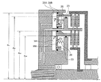
- R A1 is the outer diameter of the first piston 23
- R B1 is the outer diameter of the first centrifugal hydraulic pressure cancellation chamber 25B
- R A2 is the outer diameter of the second piston 33
- R B2 is the second centrifugal hydraulic pressure cancellation chamber 35B.
- P S is the hydraulic pressure
- F S1 is the urging force of the first return spring 26
- F S2 is the urging force of the second return spring 36.
- the biasing force of the first return spring 26 is set to be larger than the oil pressure difference between the first hydraulic pressure chamber 25A and the first centrifugal hydraulic pressure cancellation chamber 25B acting on the first piston 23, and the second return spring 36 is set. Is set to be larger than the hydraulic pressure difference between the second hydraulic chamber 35A acting on the second piston 33 and the second centrifugal hydraulic pressure cancel chamber 35B, the first and second wet clutches C1 and C2 are reliably Therefore, it is possible to effectively prevent double engagement of the transmission.
Abstract
デュアルクラッチ装置に関し、変速機の二重噛み合いを防止する。 第1油圧室(25A)に供給される油圧によって第1クラッチ(C1)を接にすると共に第1スプリング(26)によって第1クラッチを断にする第1ピストン(23)と、第2油圧室(35A)に供給される油圧によって第2クラッチ(C2)を接にすると共に第2スプリング(36)によって第2クラッチを断にする第2ピストン(33)と、第1油圧室及び第2油圧キャンセル室(35B)に油圧を供給する第1供給ライン(43,50)と、第2油圧室及び第1油圧キャンセル室(25B)に油圧を供給する第2供給ライン(45,51)と、第1油圧室及び第2油圧キャンセル室への油圧供給を許可又は遮断する第1開閉弁(60)と、第2油圧室及び第1油圧キャンセル室への油圧供給を許可又は遮断する第2開閉弁(65)とを備えた。
Description
本発明は、デュアルクラッチ装置に関する。
従来、エンジンからの動力を断接する第1クラッチに接続された第1入力シャフトと、エンジンからの動力を断接する第2クラッチに接続された第2入力シャフトとを備え、第1クラッチ及び第2クラッチを交互に切り替えることで変速を行うデュアルクラッチ式変速機が知られている(例えば、特許文献1参照)。
一般的なデュアルクラッチ式変速機は、一方のクラッチが奇数段のギヤ列に対応し、他方のクラッチが偶数段のギヤ列に対応している。このため、例えば、2速から3速にシフトアップする際は、偶数段用のクラッチを接、2速用のシンクロ機構を係合した状態で、3速用のシンクロ機構を係合する。そして、偶数段用のクラッチを切り離しつつ、奇数段用のクラッチを接続することで、トルク抜けが生じない変速を実現することができる。
一般的なデュアルクラッチ装置では、クラッチを接続する場合は、油圧室内に油圧を供給すると共に、油圧キャンセル室内から油圧を開放し、ピストンをストローク移動させてクラッチプレートを互いに圧接することで実現される。また、クラッチを切断する場合は、油圧室内の油圧を開放すると、油圧キャンセル室内のリターンスプリングがピストンをクラッチプレートから離反することで実現される。各油圧室への油圧の供給又は油圧の開放は、各油圧室にそれぞれ対応して設けられた電磁バルブのON/OFFを切り替えることで制御される。
このため、例えば、少なくとも一方の電磁バルブに断線や固着等の故障が生じると、各クラッチが接続状態で保持されて、変速機の二重噛み合いを引き起こす可能性がある。
本発明の目的は、変速機の二重噛み合いを効果的に防止することができるデュアルクラッチ装置を提供することにある。
上述の目的を達成するため、本発明のデュアルクラッチ装置は、エンジンから変速機第1入力シャフトへの動力伝達を断接する第1プレートを有する第1クラッチと、前記エンジンから変速機第2入力シャフトへの動力伝達を断接する第2プレートを有する第2クラッチとを備えるデュアルクラッチ装置であって、第1油圧室内に供給される油圧によって前記第1プレートを押圧して前記第1クラッチを接にすると共に、第1油圧キャンセル室内に収容された第1スプリングによって前記第1プレートから離反されて前記第1クラッチを断にする第1ピストンと、第2油圧室内に供給される油圧によって前記第2プレートを押圧して前記第2クラッチを接にすると共に、第2油圧キャンセル室内に収容された第2スプリングによって前記第2プレートから離反されて前記第2クラッチを断にする第2ピストンと、前記第1油圧室及び前記第2油圧キャンセル室に油圧を供給する第1供給ラインと、前記第2油圧室及び前記第1油圧キャンセル室に油圧を供給する第2供給ラインと、前記第1供給ラインに設けられて、前記第1油圧室及び前記第2油圧キャンセル室への油圧の供給を許可又は遮断する第1開閉弁と、前記第2供給ラインに設けられて、前記第2油圧室及び前記第1油圧キャンセル室への油圧の供給を許可又は遮断する第2開閉弁とを備えることを特徴とする。
また、前記第1スプリングの付勢力が、前記第1油圧室に前記第1供給ラインを介して供給されて前記第1ピストンに作用する油圧力と、前記第1油圧キャンセル室に前記第2供給ラインを介して供給されて前記第1ピストンに作用する油圧力との差よりも大きく設定されることが好ましい。
また、前記第2スプリングの付勢力が、前記第2油圧室に前記第2供給ラインを介して供給されて前記第2ピストンに作用する油圧力と、前記第2油圧キャンセル室に前記第1供給ラインを介して供給されて前記第2ピストンに作用する油圧力との差よりも大きく設定されることが好ましい。
以下、添付図面に基づいて、本発明の一実施形態に係るデュアルクラッチ装置を説明する。同一の部品には同一の符号を付してあり、それらの名称及び機能も同じである。したがって、それらについての詳細な説明は繰返さない。
図1に示すように、デュアルクラッチ装置10は、第1湿式クラッチC1と、第2湿式クラッチC2とを備えている。なお、符号11はエンジンEの動力が伝達されるクラッチ入力シャフトを示している。また、符号12Aは変速機Tの例えば奇数段を確立する変速ギヤ列が設けられた変速機第1入力シャフト、符号12Bは例えば偶数段を確立する変速ギヤ列が設けられた変速機第2入力シャフトをそれぞれ示している。第2入力シャフト12Bは、第1入力シャフト12Aの中空軸内に軸受け13を介して回転自在に軸支されている。
第1湿式クラッチC1は、クラッチ入力シャフト11と一体回転するクラッチハブ20と、クラッチハブ20にスプライン嵌合する複数枚の第1内側プレート21Aと、変速機第1入力シャフト12Aと一体回転する第1クラッチドラム22と、第1内側プレート21A間に交互に配置されて第1クラッチドラム22にスプライン嵌合する複数枚の第1外側プレート21Bと、各プレート21A,Bを軸方向に押圧可能な円筒状の第1ピストン23とを備えている。
第1ピストン23は、クラッチハブ20に形成された円環状の第1ピストン室24内に摺動自在に収容されている。この第1ピストン室24内には、第1ピストン23によって第1油圧室25A及び、第1遠心油圧キャンセル室25Bが区画形成されている。また、第1遠心油圧キャンセル室25B内には、第1ピストン23を各プレート21A,Bから離反する方向に付勢する第1リターンスプリング26が収容されている。なお、符号Sは、第1ピストン23と第1ピストン室24との隙間をシールするシール部材を示している。
第1油圧室25Aに油圧が供給されると、第1ピストン23は軸方向にストローク移動して各プレート21A,Bを互いに圧接させる(第1湿式クラッチC1:接)。一方、第1油圧室25Aの油圧が降下し、且つ第1遠心油圧キャンセル室25Bに油圧が供給されると、第1ピストン23は第1リターンスプリング26の付勢力及び、第1遠心油圧キャンセル室25B内の油圧力によって各プレート21A,Bから離反して圧接状態を開放させる(第1湿式クラッチC1:断)。
第2湿式クラッチC2は、クラッチハブ20にスプライン嵌合する複数枚の第2外側プレート31Aと、変速機第2入力シャフト12Bと一体回転する第2クラッチドラム32と、第2外側プレート31A間に交互に配置されて第2クラッチドラム32にスプライン嵌合する複数枚の第2内側プレート31Bと、各プレート31A,Bを軸方向に圧接可能な円筒状の第2ピストン33とを備えている。
第2ピストン33は、クラッチハブ20に形成された円環状の第2ピストン室34内に摺動自在に収容されている。この第2ピストン室34内には、第2ピストン33によって第2油圧室35A及び、第2遠心油圧キャンセル室35Bが区画形成されている。また、第2遠心油圧キャンセル室35B内には、第2ピストン33を各プレート31A,Bから離反する方向に付勢する第2リターンスプリング36が収容されている。なお、符号Sは、第2ピストン33と第2ピストン室34との隙間をシールするシール部材を示している。
第2油圧室35Aに油圧が供給されると、第2ピストン33は軸方向にストローク移動して各プレート31A,Bを互いに圧接させる(第2湿式クラッチC2:接)。一方、第2油圧室35Aの油圧が降下し、且つ第2遠心油圧キャンセル室35Bに油圧が供給されると、第2ピストン33は第2リターンスプリング36の付勢力及び、第2遠心油圧キャンセル室35B内の油圧力によって各プレート31A,Bから離反して圧接状態を開放させる(第2湿式クラッチC2:断)。
油圧回路40は、オイルパン41と第1電磁バルブ60とを接続する第1上流供給ライン43と、第1上流供給ライン43から分岐して第2電磁バルブ65に接続された第2上流供給ライン45とを有する。分岐部よりも上流側の第1上流供給ライン43には、エンジンEの動力で駆動するオイルポンプOPが設けられている。第2上流供給ライン45には、絞り弁47が設けられた潤滑用油供給ライン46が接続されている。
第1電磁バルブ60には、第1下流供給ライン50が接続されている。この第1下流供給ライン50は、クラッチハブ20内で第1油圧室用ライン50Aと、第2キャンセル室用ライン50Bとに分岐形成されている。第1油圧室用ライン50Aの下流端は第1油圧室25Aに接続され、第2キャンセル室用ライン50Bの下流端は第2遠心油圧キャンセル室35Bに接続されている。
第1電磁バルブ60は、非通電時(OFF)はスプリング61の付勢力によって閉とされ、図示しない電子制御ユニットにより通電(ON)されると開となる。第1電磁バルブ60が開(ON)のときは、第1油圧室25A及び第2遠心油圧キャンセル室35Bに圧油が供給される。一方、第1電磁バルブ60が閉(OFF)のときは、第1油圧室25A及び第2遠心油圧キャンセル室35Bに圧油が供給されず、第1油圧室25A及び第2遠心油圧キャンセル室35B内の圧油は油戻しライン62を介してオイルパン41に戻される。
第2電磁バルブ65には、第2下流供給ライン51が接続されている。この第2下流供給ライン51は、クラッチハブ20内で第2油圧室用ライン51Aと、第1キャンセル室用ライン51Bとに分岐形成されている。第2油圧室用ライン51Aの下流端は第2油圧室35Aに接続され、第1キャンセル室用ライン51Bの下流端は第1遠心油圧キャンセル室25Bに接続されている。
第2電磁バルブ65は、非通電時(OFF)はスプリング66の付勢力によって閉とされ、電子制御ユニットにより通電(ON)されると開となる。第2電磁バルブ65が開(ON)のときは、第2油圧室35A及び第1遠心油圧キャンセル室25Bに圧油が供給される。一方、第2電磁バルブ65が閉(OFF)のときは、第2油圧室35A及び第1遠心油圧キャンセル室25Bに圧油が供給されず、第2油圧室35A及び第1遠心油圧キャンセル室25B内の圧油は油戻しライン67を介してオイルパン41に戻される。
次に、図2,3に基づいて、デュアルクラッチ装置10の断接動作及び作用効果を説明する。
クラッチ入力シャフト11から変速機第1入力シャフト12Aに動力を伝達する場合は、図2に示すように、第1湿式クラッチC1を接(第1電磁バルブ60:ON)、第2湿式クラッチC2を断(第2電磁バルブ65:OFF)にする。
第1電磁バルブ60がONになると、第1油圧室25Aのみならず、第2遠心油圧キャンセル室35Bにも油圧が供給されるため、第2ピストン33には、第2リターンスプリング36の付勢力及び、第2遠心油圧キャンセル室35B内の油圧力の双方が作用する。その結果、例えば、第2電磁バルブ65に断線や固着等の故障が生じても、第2ピストン33を確実に各プレート31A,Bから離反させることが可能となり、変速機の二重噛み合いを確実に防止することができる。
また、クラッチ入力シャフト11から変速機第2入力シャフト12Bに動力を伝達する場合は、図3に示すように、第1湿式クラッチC1を断(第1電磁バルブ60:OFF)、第2湿式クラッチC2を接(第2電磁バルブ65:ON)にする。
第2電磁バルブ65がONになると、第2油圧室35Aのみならず、第1遠心油圧キャンセル室25Bにも油圧が供給されるため、第1ピストン23には、第1リターンスプリング26の付勢力及び、第1遠心油圧キャンセル室25B内の油圧力の双方が作用する。その結果、例えば、第1電磁バルブ60に断線や固着等の故障が生じても、第1ピストン23を確実に各プレート21A,Bから離反させることが可能となり、変速機の二重噛み合いを確実に防止することができる。
次に、図4に基づいて、各リターンスプリング26,36の最適な付勢力の設定について説明する。
図4において、RA1は第1ピストン23の外径、RB1は第1遠心油圧キャンセル室25Bの外径、RA2は第2ピストン33の外径、RB2は第2遠心油圧キャンセル室35Bの外径、Pは油圧、FS1は第1リターンスプリング26の付勢力、FS2は第2リターンスプリング36の付勢力をそれぞれ示している。これらが、以下の条件式(1),(2)を満たす場合に、第1及び第2電磁バルブ60,65が同時にONにされても、第1及び第2湿式クラッチC1,2を確実に切断することが可能になる。
このように、第1リターンスプリング26の付勢力を、第1ピストン23に作用する第1油圧室25Aと第1遠心油圧キャンセル室25Bとの油圧力差よりも大きく設定し、第2リターンスプリング36の付勢力を、第2ピストン33に作用する第2油圧室35Aと第2遠心油圧キャンセル室35Bとの油圧力差よりも大きく設定することで、第1及び第2湿式クラッチC1,C2が確実に切断されることになり、変速機の二重噛み合いを効果的に防止することが可能になる。
なお、本発明は、上述の実施形態に限定されるものではなく、本発明の趣旨を逸脱しない範囲で、適宜変形して実施することが可能である。
Claims (3)
- エンジンから変速機第1入力シャフトへの動力伝達を断接する第1プレートを有する第1クラッチと、前記エンジンから変速機第2入力シャフトへの動力伝達を断接する第2プレートを有する第2クラッチとを備えるデュアルクラッチ装置であって、
第1油圧室内に供給される油圧によって前記第1プレートを押圧して前記第1クラッチを接にすると共に、第1油圧キャンセル室内に収容された第1スプリングによって前記第1プレートから離反されて前記第1クラッチを断にする第1ピストンと、
第2油圧室内に供給される油圧によって前記第2プレートを押圧して前記第2クラッチを接にすると共に、第2油圧キャンセル室内に収容された第2スプリングによって前記第2プレートから離反されて前記第2クラッチを断にする第2ピストンと、
前記第1油圧室及び前記第2油圧キャンセル室に油圧を供給する第1供給ラインと、
前記第2油圧室及び前記第1油圧キャンセル室に油圧を供給する第2供給ラインと、
前記第1供給ラインに設けられて、前記第1油圧室及び前記第2油圧キャンセル室への油圧の供給を許可又は遮断する第1開閉弁と、
前記第2供給ラインに設けられて、前記第2油圧室及び前記第1油圧キャンセル室への油圧の供給を許可又は遮断する第2開閉弁と、を備える
ことを特徴とするデュアルクラッチ装置。 - 前記第1スプリングの付勢力が、前記第1油圧室に前記第1供給ラインを介して供給されて前記第1ピストンに作用する油圧力と、前記第1油圧キャンセル室に前記第2供給ラインを介して供給されて前記第1ピストンに作用する油圧力との差よりも大きく設定される
請求項1に記載のデュアルクラッチ装置。 - 前記第2スプリングの付勢力が、前記第2油圧室に前記第2供給ラインを介して供給されて前記第2ピストンに作用する油圧力と、前記第2油圧キャンセル室に前記第1供給ラインを介して供給されて前記第2ピストンに作用する油圧力との差よりも大きく設定される
請求項1又は2に記載のデュアルクラッチ装置。
Priority Applications (3)
| Application Number | Priority Date | Filing Date | Title |
|---|---|---|---|
| CN201580020026.5A CN106795925B (zh) | 2014-04-18 | 2015-04-16 | 双离合装置 |
| EP15779222.7A EP3133310B1 (en) | 2014-04-18 | 2015-04-16 | Dual clutch device |
| US15/304,832 US10400835B2 (en) | 2014-04-18 | 2015-04-16 | Dual clutch device |
Applications Claiming Priority (2)
| Application Number | Priority Date | Filing Date | Title |
|---|---|---|---|
| JP2014-086378 | 2014-04-18 | ||
| JP2014086378A JP6384099B2 (ja) | 2014-04-18 | 2014-04-18 | デュアルクラッチ装置 |
Publications (1)
| Publication Number | Publication Date |
|---|---|
| WO2015159955A1 true WO2015159955A1 (ja) | 2015-10-22 |
Family
ID=54324156
Family Applications (1)
| Application Number | Title | Priority Date | Filing Date |
|---|---|---|---|
| PCT/JP2015/061733 WO2015159955A1 (ja) | 2014-04-18 | 2015-04-16 | デュアルクラッチ装置 |
Country Status (5)
| Country | Link |
|---|---|
| US (1) | US10400835B2 (ja) |
| EP (1) | EP3133310B1 (ja) |
| JP (1) | JP6384099B2 (ja) |
| CN (1) | CN106795925B (ja) |
| WO (1) | WO2015159955A1 (ja) |
Cited By (8)
| Publication number | Priority date | Publication date | Assignee | Title |
|---|---|---|---|---|
| WO2016093353A1 (ja) * | 2014-12-11 | 2016-06-16 | いすゞ自動車株式会社 | デュアルクラッチ装置 |
| WO2018057899A1 (en) * | 2016-09-22 | 2018-03-29 | Linamar Corporation | Integrated disconnecting twin clutch system and dual action piston |
| CN108884934A (zh) * | 2016-03-29 | 2018-11-23 | 马自达汽车株式会社 | 自动变速器及摩擦接合单元 |
| EP3404280A4 (en) * | 2016-02-23 | 2018-12-05 | Mazda Motor Corporation | Automatic transmission |
| RU2694426C1 (ru) * | 2018-05-07 | 2019-07-12 | Федеральное государственное унитарное предприятие "Центральный ордена Трудового Красного Знамени научно-исследовательский автомобильный и автомоторный институт "НАМИ" (ФГУП "НАМИ") | Двойная фрикционная муфта сцепления с гидравлическим управлением |
| RU2708963C1 (ru) * | 2019-03-04 | 2019-12-12 | Федеральное государственное унитарное предприятие "Центральный ордена Трудового Красного Знамени научно-исследовательский автомобильный и автомоторный институт "НАМИ" (ФГУП "НАМИ") | Двойная фрикционная муфта сцепления |
| DE102017004735B4 (de) * | 2016-05-19 | 2020-11-26 | Mazda Motor Corporation | Automatikgetriebe, Verfahren zum Steuern desselben, sowie Computerprogrammprodukt |
| DE102017004745B4 (de) * | 2016-05-19 | 2020-11-26 | Mazda Motor Corporation | Automatikgetriebe und Computerprogrammprodukt |
Families Citing this family (5)
| Publication number | Priority date | Publication date | Assignee | Title |
|---|---|---|---|---|
| JP6315006B2 (ja) | 2016-02-23 | 2018-04-25 | マツダ株式会社 | 摩擦締結要素及び自動変速機 |
| JP6489039B2 (ja) | 2016-02-23 | 2019-03-27 | マツダ株式会社 | 自動変速機 |
| RU2662337C1 (ru) * | 2017-07-05 | 2018-07-25 | Федеральное государственное унитарное предприятие "Центральный ордена Трудового Красного Знамени научно-исследовательский автомобильный и автомоторный институт "НАМИ" (ФГУП "НАМИ") | Двойное сцепление трансмиссии транспортного средства |
| FR3068746B1 (fr) * | 2017-07-06 | 2020-02-28 | Valeo Embrayages | Porte-disque de sortie d'un double embrayages et mecanisme comprenant un tel porte-disque |
| RU2670340C1 (ru) * | 2017-12-05 | 2018-10-22 | Федеральное государственное унитарное предприятие "Центральный ордена Трудового Красного Знамени научно-исследовательский автомобильный и автомоторный институт "НАМИ" (ФГУП "НАМИ") | Двойное сцепление для трансмиссий транспортных средств |
Citations (2)
| Publication number | Priority date | Publication date | Assignee | Title |
|---|---|---|---|---|
| JP2004036807A (ja) * | 2002-07-05 | 2004-02-05 | Aisin Aw Co Ltd | 変速機の油圧制御装置 |
| JP2013024331A (ja) * | 2011-07-21 | 2013-02-04 | Nsk Ltd | 無段変速装置 |
Family Cites Families (11)
| Publication number | Priority date | Publication date | Assignee | Title |
|---|---|---|---|---|
| JP2816768B2 (ja) * | 1990-12-17 | 1998-10-27 | アイシン・エィ・ダブリュ株式会社 | 自動変速機における油圧アクチュエータ装置 |
| DE19931973A1 (de) * | 1999-07-09 | 2001-01-11 | Wabco Gmbh & Co Ohg | Einrichtung zum Steuern einer Stelleinrichtung für ein Getriebe |
| DE10121632A1 (de) | 2001-05-03 | 2002-11-07 | Zahnradfabrik Friedrichshafen | Schaltbares Getriebe |
| DE102004034540B4 (de) * | 2004-07-16 | 2013-07-25 | Zf Friedrichshafen Ag | Kupplungsanordnung mit einer Kühlkammer |
| DE102006054032A1 (de) | 2006-11-16 | 2008-05-21 | Zf Friedrichshafen Ag | Steuerungsvorrichtung für ein Getriebe und Verfahren zur Steuerung eines Getriebes |
| DE102007029634A1 (de) | 2007-06-26 | 2009-01-08 | Daimler Ag | Zahnräderwechselgetriebe |
| JP5455500B2 (ja) * | 2009-08-07 | 2014-03-26 | 株式会社エフ・シー・シー | 動力伝達装置 |
| JP5513199B2 (ja) * | 2010-03-26 | 2014-06-04 | 本田技研工業株式会社 | エンジンの油圧クラッチ用油路構造 |
| US8858394B2 (en) * | 2011-09-23 | 2014-10-14 | Chrysler Group Llc | Apparatus and method for automated transmission clutch fill during engine start-stop operation |
| CN104040205B (zh) * | 2011-12-22 | 2017-06-06 | 舍弗勒技术股份两合公司 | 双离合器 |
| DE102014226150A1 (de) * | 2014-12-17 | 2016-06-23 | Zf Friedrichshafen Ag | Hydrauliksystem für ein Automatikgetriebe |
-
2014
- 2014-04-18 JP JP2014086378A patent/JP6384099B2/ja active Active
-
2015
- 2015-04-16 EP EP15779222.7A patent/EP3133310B1/en active Active
- 2015-04-16 CN CN201580020026.5A patent/CN106795925B/zh active Active
- 2015-04-16 US US15/304,832 patent/US10400835B2/en active Active
- 2015-04-16 WO PCT/JP2015/061733 patent/WO2015159955A1/ja active Application Filing
Patent Citations (2)
| Publication number | Priority date | Publication date | Assignee | Title |
|---|---|---|---|---|
| JP2004036807A (ja) * | 2002-07-05 | 2004-02-05 | Aisin Aw Co Ltd | 変速機の油圧制御装置 |
| JP2013024331A (ja) * | 2011-07-21 | 2013-02-04 | Nsk Ltd | 無段変速装置 |
Non-Patent Citations (1)
| Title |
|---|
| See also references of EP3133310A4 * |
Cited By (13)
| Publication number | Priority date | Publication date | Assignee | Title |
|---|---|---|---|---|
| US10274024B2 (en) | 2014-12-11 | 2019-04-30 | Isuzu Motors Limited | Dual clutch apparatus |
| JP2016114086A (ja) * | 2014-12-11 | 2016-06-23 | いすゞ自動車株式会社 | デュアルクラッチ装置 |
| WO2016093353A1 (ja) * | 2014-12-11 | 2016-06-16 | いすゞ自動車株式会社 | デュアルクラッチ装置 |
| US10746234B2 (en) | 2016-02-23 | 2020-08-18 | Mazda Motor Corporation | Automatic transmission |
| EP3404280A4 (en) * | 2016-02-23 | 2018-12-05 | Mazda Motor Corporation | Automatic transmission |
| CN108884934A (zh) * | 2016-03-29 | 2018-11-23 | 马自达汽车株式会社 | 自动变速器及摩擦接合单元 |
| CN108884934B (zh) * | 2016-03-29 | 2020-06-12 | 马自达汽车株式会社 | 自动变速器及摩擦接合单元 |
| DE102017004735B4 (de) * | 2016-05-19 | 2020-11-26 | Mazda Motor Corporation | Automatikgetriebe, Verfahren zum Steuern desselben, sowie Computerprogrammprodukt |
| DE102017004745B4 (de) * | 2016-05-19 | 2020-11-26 | Mazda Motor Corporation | Automatikgetriebe und Computerprogrammprodukt |
| WO2018057899A1 (en) * | 2016-09-22 | 2018-03-29 | Linamar Corporation | Integrated disconnecting twin clutch system and dual action piston |
| US11187281B2 (en) | 2016-09-22 | 2021-11-30 | Linamar Corporation | Integrated disconnecting twin clutch system and dual action piston |
| RU2694426C1 (ru) * | 2018-05-07 | 2019-07-12 | Федеральное государственное унитарное предприятие "Центральный ордена Трудового Красного Знамени научно-исследовательский автомобильный и автомоторный институт "НАМИ" (ФГУП "НАМИ") | Двойная фрикционная муфта сцепления с гидравлическим управлением |
| RU2708963C1 (ru) * | 2019-03-04 | 2019-12-12 | Федеральное государственное унитарное предприятие "Центральный ордена Трудового Красного Знамени научно-исследовательский автомобильный и автомоторный институт "НАМИ" (ФГУП "НАМИ") | Двойная фрикционная муфта сцепления |
Also Published As
| Publication number | Publication date |
|---|---|
| CN106795925A (zh) | 2017-05-31 |
| EP3133310A1 (en) | 2017-02-22 |
| US10400835B2 (en) | 2019-09-03 |
| CN106795925B (zh) | 2018-10-26 |
| EP3133310A4 (en) | 2018-01-03 |
| JP2015206390A (ja) | 2015-11-19 |
| EP3133310B1 (en) | 2019-10-23 |
| US20170184160A1 (en) | 2017-06-29 |
| JP6384099B2 (ja) | 2018-09-05 |
Similar Documents
| Publication | Publication Date | Title |
|---|---|---|
| JP6384099B2 (ja) | デュアルクラッチ装置 | |
| US10040445B2 (en) | Drivetrain for a motor vehicle, and method for operating a drivetrain of said type | |
| JP4938553B2 (ja) | ツインクラッチ装置 | |
| ITMI20010306A1 (it) | Dispositivo di trasmissione di momento torcente con almeno un primo dispositivo di frizione nonche' almeno un secondo dispositivo di frizion | |
| US8424661B2 (en) | Power transmitting apparatus | |
| US10274024B2 (en) | Dual clutch apparatus | |
| WO2017209229A1 (ja) | デュアルクラッチ式変速機の制御装置 | |
| CN108291631B (zh) | 双离合器式变速器的控制装置和双离合器式变速器 | |
| US20200318730A1 (en) | Dual-clutch actuator and drive assembly having such an actuator | |
| KR20140025147A (ko) | 더블클러치 변속기의 싱크 제어 방법 | |
| JP2006312998A (ja) | 動力伝達装置 | |
| JP2013210077A (ja) | 車両用パワーユニットにおけるクラッチ制御装置 | |
| JP5846965B2 (ja) | クラッチ装置 | |
| JP2017040305A (ja) | クラッチ制御装置 | |
| JP2015190491A (ja) | 動力伝達装置の制御装置及び制御方法 | |
| JP2017040306A (ja) | クラッチ制御装置 | |
| EP3382236B1 (en) | Control device for dual clutch transmission | |
| KR102487191B1 (ko) | 자동변속기용 동력전달장치 | |
| US10975935B2 (en) | Dual clutch-type transmission | |
| JP7040154B2 (ja) | 自動変速機の油圧制御装置 | |
| JP6551191B2 (ja) | 作動油制御装置 | |
| MX2020000617A (es) | Lubricacion del sistema de embrague. | |
| JP2018100737A (ja) | 摩擦締結要素の潤滑制御装置 | |
| WO2017090624A1 (ja) | 作動油制御装置 | |
| JP2019031998A (ja) | 変速制御装置 |
Legal Events
| Date | Code | Title | Description |
|---|---|---|---|
| 121 | Ep: the epo has been informed by wipo that ep was designated in this application |
Ref document number: 15779222 Country of ref document: EP Kind code of ref document: A1 |
|
| REEP | Request for entry into the european phase |
Ref document number: 2015779222 Country of ref document: EP |
|
| WWE | Wipo information: entry into national phase |
Ref document number: 15304832 Country of ref document: US Ref document number: 2015779222 Country of ref document: EP |
|
| NENP | Non-entry into the national phase |
Ref country code: DE |