WO2015159883A1 - 搬送補助装置 - Google Patents
搬送補助装置 Download PDFInfo
- Publication number
- WO2015159883A1 WO2015159883A1 PCT/JP2015/061472 JP2015061472W WO2015159883A1 WO 2015159883 A1 WO2015159883 A1 WO 2015159883A1 JP 2015061472 W JP2015061472 W JP 2015061472W WO 2015159883 A1 WO2015159883 A1 WO 2015159883A1
- Authority
- WO
- WIPO (PCT)
- Prior art keywords
- unit
- distance
- drive unit
- drive
- detection
- Prior art date
- Legal status (The legal status is an assumption and is not a legal conclusion. Google has not performed a legal analysis and makes no representation as to the accuracy of the status listed.)
- Ceased
Links
Images





Classifications
-
- A—HUMAN NECESSITIES
- A61—MEDICAL OR VETERINARY SCIENCE; HYGIENE
- A61G—TRANSPORT, PERSONAL CONVEYANCES, OR ACCOMMODATION SPECIALLY ADAPTED FOR PATIENTS OR DISABLED PERSONS; OPERATING TABLES OR CHAIRS; CHAIRS FOR DENTISTRY; FUNERAL DEVICES
- A61G7/00—Beds specially adapted for nursing; Devices for lifting patients or disabled persons
- A61G7/08—Apparatus for transporting beds
-
- A—HUMAN NECESSITIES
- A61—MEDICAL OR VETERINARY SCIENCE; HYGIENE
- A61G—TRANSPORT, PERSONAL CONVEYANCES, OR ACCOMMODATION SPECIALLY ADAPTED FOR PATIENTS OR DISABLED PERSONS; OPERATING TABLES OR CHAIRS; CHAIRS FOR DENTISTRY; FUNERAL DEVICES
- A61G7/00—Beds specially adapted for nursing; Devices for lifting patients or disabled persons
- A61G7/05—Parts, details or accessories of beds
- A61G7/0506—Head or foot boards
-
- A—HUMAN NECESSITIES
- A61—MEDICAL OR VETERINARY SCIENCE; HYGIENE
- A61G—TRANSPORT, PERSONAL CONVEYANCES, OR ACCOMMODATION SPECIALLY ADAPTED FOR PATIENTS OR DISABLED PERSONS; OPERATING TABLES OR CHAIRS; CHAIRS FOR DENTISTRY; FUNERAL DEVICES
- A61G7/00—Beds specially adapted for nursing; Devices for lifting patients or disabled persons
- A61G7/05—Parts, details or accessories of beds
- A61G7/0528—Steering or braking devices for castor wheels
-
- A—HUMAN NECESSITIES
- A61—MEDICAL OR VETERINARY SCIENCE; HYGIENE
- A61G—TRANSPORT, PERSONAL CONVEYANCES, OR ACCOMMODATION SPECIALLY ADAPTED FOR PATIENTS OR DISABLED PERSONS; OPERATING TABLES OR CHAIRS; CHAIRS FOR DENTISTRY; FUNERAL DEVICES
- A61G2203/00—General characteristics of devices
- A61G2203/10—General characteristics of devices characterised by specific control means, e.g. for adjustment or steering
- A61G2203/14—Joysticks
-
- A—HUMAN NECESSITIES
- A61—MEDICAL OR VETERINARY SCIENCE; HYGIENE
- A61G—TRANSPORT, PERSONAL CONVEYANCES, OR ACCOMMODATION SPECIALLY ADAPTED FOR PATIENTS OR DISABLED PERSONS; OPERATING TABLES OR CHAIRS; CHAIRS FOR DENTISTRY; FUNERAL DEVICES
- A61G2203/00—General characteristics of devices
- A61G2203/30—General characteristics of devices characterised by sensor means
- A61G2203/32—General characteristics of devices characterised by sensor means for force
-
- A—HUMAN NECESSITIES
- A61—MEDICAL OR VETERINARY SCIENCE; HYGIENE
- A61G—TRANSPORT, PERSONAL CONVEYANCES, OR ACCOMMODATION SPECIALLY ADAPTED FOR PATIENTS OR DISABLED PERSONS; OPERATING TABLES OR CHAIRS; CHAIRS FOR DENTISTRY; FUNERAL DEVICES
- A61G2203/00—General characteristics of devices
- A61G2203/30—General characteristics of devices characterised by sensor means
- A61G2203/40—General characteristics of devices characterised by sensor means for distance
-
- A—HUMAN NECESSITIES
- A61—MEDICAL OR VETERINARY SCIENCE; HYGIENE
- A61G—TRANSPORT, PERSONAL CONVEYANCES, OR ACCOMMODATION SPECIALLY ADAPTED FOR PATIENTS OR DISABLED PERSONS; OPERATING TABLES OR CHAIRS; CHAIRS FOR DENTISTRY; FUNERAL DEVICES
- A61G2203/00—General characteristics of devices
- A61G2203/70—General characteristics of devices with special adaptations, e.g. for safety or comfort
- A61G2203/72—General characteristics of devices with special adaptations, e.g. for safety or comfort for collision prevention
-
- A—HUMAN NECESSITIES
- A61—MEDICAL OR VETERINARY SCIENCE; HYGIENE
- A61G—TRANSPORT, PERSONAL CONVEYANCES, OR ACCOMMODATION SPECIALLY ADAPTED FOR PATIENTS OR DISABLED PERSONS; OPERATING TABLES OR CHAIRS; CHAIRS FOR DENTISTRY; FUNERAL DEVICES
- A61G5/00—Chairs or personal conveyances specially adapted for patients or disabled persons, e.g. wheelchairs
- A61G5/04—Chairs or personal conveyances specially adapted for patients or disabled persons, e.g. wheelchairs motor-driven
- A61G5/047—Chairs or personal conveyances specially adapted for patients or disabled persons, e.g. wheelchairs motor-driven by a modular detachable drive system
-
- Y—GENERAL TAGGING OF NEW TECHNOLOGICAL DEVELOPMENTS; GENERAL TAGGING OF CROSS-SECTIONAL TECHNOLOGIES SPANNING OVER SEVERAL SECTIONS OF THE IPC; TECHNICAL SUBJECTS COVERED BY FORMER USPC CROSS-REFERENCE ART COLLECTIONS [XRACs] AND DIGESTS
- Y02—TECHNOLOGIES OR APPLICATIONS FOR MITIGATION OR ADAPTATION AGAINST CLIMATE CHANGE
- Y02T—CLIMATE CHANGE MITIGATION TECHNOLOGIES RELATED TO TRANSPORTATION
- Y02T10/00—Road transport of goods or passengers
- Y02T10/60—Other road transportation technologies with climate change mitigation effect
- Y02T10/72—Electric energy management in electromobility
Definitions
- the present invention relates to a conveyance auxiliary device used when a carrier conveys an object.
- Patent Document 1 includes a traveling carriage attached to the front end portion of a bed and an operating device attached to the rear end portion of the bed, and a pair of gripping members of the operating device by a carrier on the rear end side of the bed.
- a conveyance auxiliary device that detects left and right forces applied to the vehicle and controls the traveling carriage based on the left and right forces.
- the conveyance auxiliary device In the conveyance auxiliary device, an input operation is performed with the left and right hands of the carrier with respect to the left and right operation input units such as the pair of gripping members.
- the conveyance auxiliary device may detect that the carrier has released either the left or right hand (one hand) from the operation unit and cause the drive unit to perform an emergency stop (sudden stop). Conceivable.
- the driving unit is suddenly stopped, the moving bed is decelerated rapidly at a predetermined speed. As a result, a large inertial force in the forward direction acts on the person lying on the bed, which may cause discomfort.
- an object of the present invention is to provide a conveyance assisting device that prevents sudden deceleration when the carrier removes one hand from the operation unit.
- a conveyance auxiliary device is a conveyance auxiliary device that is used when a carrier conveys an object, a driving unit that is attached to the object and assists in conveying the object, and an object
- An operation unit having a left operation input unit that is attached to an object and that inputs an operation on the drive unit by the left hand of the transporter; and a right operation input unit that inputs an operation on the drive unit by the right hand of the transporter;
- a first control unit that controls the drive unit according to each operation amount input to the operation input unit and the right operation input unit, and a left hand that detects whether or not the left hand of the carrier is in contact with the left operation input unit
- a right hand detection unit that detects whether or not the right hand of the transporter is in contact with the right operation input unit, and the first control unit includes the left hand of the transporter and the left hand of the transporter by the left hand detection unit and the right hand detection unit. If it is detected that one side of the right hand is not touching, The part is decelerated at
- the first control unit controls the drive unit according to the operation, and the drive unit assists the transport of the object.
- the transporter can transport the object with the assistance of the drive unit.
- the operation unit includes a left operation input unit and a right operation input unit, and the carrier performs an operation on the left operation input unit with the left hand and performs an operation on the right operation input unit with the right hand.
- the conveyance assist device detects whether the left hand is in contact with the left operation input unit by the left hand detection unit and inputs the right operation by the right hand detection unit. It is detected whether the right hand is in contact with the part.
- the carrier removes only one hand from the operation unit to do something temporarily.
- the first control unit moves the drive unit at a predetermined deceleration. Decelerate.
- the predetermined deceleration is a deceleration that does not cause a large inertial force to act on the object itself or an object placed on the object due to deceleration, and the object placed on the object itself or the object, etc. It should be set in consideration.
- the drive unit decelerates at a predetermined deceleration, and a large inertial force is applied to the target object and the object placed on the target object. Does not work.
- the conveyance assisting device can prevent sudden deceleration because the drive unit decelerates at a predetermined deceleration when the carrier releases one hand from the operation unit.
- the object can be transported (movable) by a person, for example, a bed having a caster, a loading platform having a caster, or an apparatus having a caster.
- the object is transported by a plurality of persons when there is no assistance by the transport assist device.
- the first control unit causes the driving unit to emergency stop when the left hand detection unit and the right hand detection unit detect that both the left hand and the right hand of the carrier are not in contact. May be.
- the transport auxiliary device having this configuration, when the left hand detection unit and the right hand detection unit detect that the left hand and the right hand of the transporter are not in contact, the first control unit makes an emergency stop (rapid stop) Control). As a result, the driving unit immediately stops. In this way, the transport assisting device can ensure safety because the drive unit immediately stops when the transporter releases both hands from the operation unit.
- emergency stop rapid stop
- the operation detection unit detects whether or not the operation unit is attached to the object
- the attachment detection unit detects that the operation unit is not attached to the object.
- a state determination unit that disables operation on the operation unit.
- the carrier cannot convey the object via the operation unit, and the carrier can operate the operation unit (left operation input unit, right operation input unit). Cannot operate normally.
- the state determination unit disables the operation on the operation unit. As a result, the drive unit is not controlled via the operation unit.
- the conveyance assist device includes a lateral movement operation input unit to which an operation for moving the drive unit in the lateral direction is input.
- the lateral movement operation input unit includes a left operation input unit and a right operation input unit. You may arrange
- the distance detection unit that detects the distance from the drive unit to the obstacle and the drive unit according to the operation of the operation unit by the carrier, and the distance detection unit detects the distance.
- a second control unit for stopping the drive unit when the distance is equal to or less than the first threshold distance; an approach operation input unit for inputting an approach operation for approaching the drive unit to the obstacle to a distance less than the first threshold distance;
- the second control unit interrupts stopping the drive unit based on the distance detected by the distance detection unit, and sets the speed of the drive unit to a predetermined value. You may limit it to speed.
- the second control unit controls the drive unit according to the operation.
- the transporter can transport the object with the assistance of the drive unit.
- the drive of the drive unit is stopped by the second control unit. The Thereby, the drive unit can be stopped in front of the obstacle.
- the first threshold distance is a distance that can be stopped before the drive unit hits (contacts) the obstacle.
- the drive unit (and hence the object) can be brought close to the wall or the like.
- the speed of the drive unit is limited to a predetermined speed (because the drive unit is decelerated)
- the second control unit can be brought close to the wall or the like and stopped.
- the predetermined speed is a very low speed that can be stopped immediately.
- the drive unit (and thus the object) can be brought close to the obstacle.
- the interruption of the drive of the drive unit based on the distance detected by the distance detection unit is not only configured to be interrupted by invalidating the stop control for the drive unit, but also by invalidating the detection by the distance detection unit.
- the structure which interrupts may be sufficient, and the structure interrupted by making 1st threshold distance small (for example, set to 0) may be sufficient.
- the object is transportable (movable) by a person, and examples thereof include a bed having a caster, a loading platform having a caster, and a device having a caster.
- the object is transported by a plurality of persons when there is no assistance by the transport assist device.
- the obstacle is an obstacle when the object is being transported, such as a person, a wall, or an object placed on the transport path.
- the conveyance auxiliary device includes a short-distance detection unit capable of detecting a distance shorter than the shortest distance that can be detected by the distance detection unit, and the second control is performed when an approach operation is input to the approach operation input unit.
- the unit may stop the driving unit when the distance detected by the short-range detection unit is equal to or less than the second threshold distance.
- the conveyance auxiliary device with this configuration can prevent the drive unit from hitting an obstacle even when an approach operation is input to the approach operation input unit.
- the second threshold distance is a distance shorter than the first threshold distance. In this way, the conveyance assisting device can prevent the driving unit from hitting the obstacle even when the conveyance assisting device is approaching the obstacle.
- the second threshold distance may be set according to the environment in which the object is conveyed. Since the conveyance auxiliary device having this configuration can appropriately set the second threshold distance according to the environment in which the object is conveyed, the drive unit can be prevented from hitting an obstacle under various environments.
- the distance detection unit includes a plurality of distance detection units having different detection directions
- the second control unit detects a direction in which the drive unit is going to travel among the plurality of distance detection units. You may control using the distance detected by the distance detection part included in an area
- the drive unit when the drive unit is going straight ahead (when a straight ahead operation is performed), the drive unit tries to go straight, detected by the distance detection unit including the direction to go straight in the detection area. It can be controlled based on the distance to the obstacle present in the direction, and when the drive unit is going to bend along the curve (when it is operated to bend), it detects the direction to bend
- the drive unit can be controlled based on the distance to the obstacle that exists in the direction of bending detected by the distance detection unit included in the region. As a result, it is possible to detect the distance to the obstacle with high accuracy regardless of whether the vehicle is going straight or turning.
- a conveyance auxiliary device is a conveyance auxiliary device used when a carrier conveys an object, and is mounted on the object and assists conveyance of the object, and a conveyance An operation unit for the operator to operate the drive unit, a distance detection unit for detecting the distance from the drive unit to the obstacle, and the drive unit according to the operation of the carrier to the operation unit, and the distance detection
- the second control unit that stops the driving unit and the approach that inputs the driving unit to the obstacle to a distance less than the first threshold distance are input.
- the second control unit interrupts stopping the drive unit based on the distance detected by the distance detection unit, and the drive unit Is limited to a predetermined speed.
- the second control unit controls the drive unit according to the operation.
- the transporter can transport the object with the assistance of the drive unit.
- the conveyance assist device detects the distance from the drive unit to the obstacle by the distance detection unit, and when the detection distance is equal to or less than the first threshold distance, the second control unit stops the drive unit. . Thereby, the drive unit can be stopped in front of the obstacle.
- the first threshold distance is a distance that can be stopped before the drive unit hits an obstacle.
- the second control unit interrupts stop control based on the detection distance detected by the distance detection unit, and the speed of the drive unit.
- the predetermined speed is a very low speed that can be stopped immediately.
- the conveyance auxiliary device can bring the drive unit (and thus the object) closer to the obstacle.
- the suspension of stop control based on the distance detected by the distance detection unit is interrupted not only by disabling stop control for the drive unit but also by disabling detection by the distance detection unit.
- the structure may be sufficient and the structure interrupted by making 1st threshold distance small (for example, set to 0) may be sufficient.
- the object is transportable (movable) by a person, and examples thereof include a bed having a caster, a loading platform having a caster, and a device having a caster.
- the object is transported by a plurality of persons when there is no assistance by the transport assist device.
- the obstacle is an obstacle when the object is being transported, such as a person, a wall, or an object placed on the transport path.
- the drive unit when the carrier removes one hand from the operation unit, the drive unit is decelerated at a predetermined deceleration, so that sudden deceleration can be prevented.
- FIG. 1 is a diagram schematically illustrating a state in which the conveyance auxiliary device according to the first embodiment is mounted on a bed.
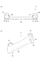
- 2A is a plan view of the operation handle of the conveyance assisting device in FIG. 1
- FIG. 2B is a perspective view of the operation handle of the conveyance assisting device in FIG.
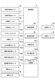
- FIG. 3 is a block diagram showing a control configuration of the conveyance assisting device of FIG.
- FIG. 4 is a diagram schematically illustrating a state in which the conveyance auxiliary device according to the second embodiment is mounted on a bed.
- 5A is a plan view of the operation handle of the conveyance assisting device in FIG. 4
- FIG. 5B is a perspective view of the operation handle of the conveyance assisting device in FIG. FIG.
- FIG. 6 is a block diagram illustrating a control configuration of the conveyance assisting device in FIG. 4.
- FIG. 7 is a diagram schematically showing detection ranges and threshold distances of three ultrasonic sensors and one short-range ultrasonic sensor of the conveyance assisting device of FIG.
- FIG. 8A is a plan view of the operation handle of the conveyance auxiliary device according to the third embodiment
- FIG. 8B is a perspective view of the operation handle of the conveyance auxiliary device according to the third embodiment.
- FIG. 9 is a block diagram illustrating a control configuration of the transport assisting apparatus according to the third embodiment.
- the transport assisting apparatus 1 is used when a single transporter (for example, a nurse) transports a movable bed having casters, and assists the transport of the bed by a single transporter.
- the transport assisting device 1 is mounted on the bed when transported, and is removed from the bed except when transported.
- the carrier conveys the bed while pushing the bed at the rear end side (one end side in the longitudinal direction to be described later) and operates the conveyance assisting device. Therefore, a bed that has conventionally been transported by two transporters can be transported by one transporter on the rear end side, and the transport assisting device plays the role of a conventional transporter on the front end side.
- the longitudinal direction of the bed is the front-rear direction
- the carrier side is the rear direction
- the other side is the front direction.
- the direction orthogonal to the front-rear direction is the left-right direction (lateral direction)
- the left hand side of the carrier is the left direction
- the right hand side of the carrier is the right direction.
- the movement of the bed includes forward and backward movements that move the bed in the front-rear direction.
- the movement of the bed includes a left movement for moving the left-right direction (direction orthogonal to the front-rear direction) to the left and a right movement for moving the left-right direction to the right.
- the movement of the bed includes a left turn (turning counterclockwise on the spot) and a right turn (turning clockwise on the spot) for turning the bed.
- FIG. 1 is a diagram schematically illustrating a state in which the conveyance auxiliary device 1 according to the first embodiment is mounted on a bed B.
- the conveyance auxiliary device 1 includes an operation handle 2 (operation unit) and a drive unit 3 (drive unit).
- the operation handle 2 is attached to the rear end of the bed B, and the drive unit 3 is attached to the front end of the bed B.
- the drive unit 3 is controlled according to each operation.
- the transport assisting device 1 decelerates and stops when the transporter P releases one hand from the operation handle 2 while transporting the bed B, and stops emergency when the both hands are released.
- the bed B includes a bed height adjusting mechanism Bb provided on the lower side of the bed main body Ba, and casters Bc attached to four corners at the bottom of the bed height adjusting mechanism Bb.
- the bed height adjusting mechanism Bb is a conventional well-known mechanism and adjusts the height position of the bed main body Ba.
- the caster Bc has a shaft and wheels. The shaft is attached to be rotatable about a vertical axis, and the wheel is attached to the lower part of the shaft to be rotatable about a horizontal axis.
- Boards Bd and Be are respectively attached to the bed main body Ba at the front end and the rear end in the longitudinal direction.
- a mattress Bf is installed on the upper surface of the bed main body Ba.
- FIG. 2A is a plan view of the operation handle
- FIG. 2B is a perspective view of the operation handle
- FIG. 3 is a block diagram illustrating a control configuration of the conveyance assisting device 1.
- the operation handle 2 is attached to the upper part of the board Be at the rear end of the bed B and is gripped by the left hand LH and the right hand RH of the carrier P.
- each operation on the drive unit 3 is input by the left hand LH and the right hand RH.
- Each operation includes an operation of pushing and pulling with the left hand LH and the right hand RH, and an ON / OFF operation for each switch.
- the operation handle 2 has a main body 2a and clamp portions 2b and 2b.
- the main body 2a is substantially plate-shaped and has a predetermined length in consideration of the distance between the left and right hands of a person.
- the clamp portions 2b and 2b are substantially L-shaped members for clamping the board Be between the main body 2a and are attached to the left and right end portions of the front surface of the main body 2a.
- the operation handle 2 is attached to the board Be by clamping the board Be with the main body 2a and the left and right clamp portions 2b and 2b sandwiched from above.
- Left and right operation grips 2c and right operation grips 2d are provided at left and right end portions (portions straddling the upper surface of the main body 2a and the upper surfaces of the clamp portions 2b and 2b) on the upper surface of the operation handle 2.
- the left operation grip (left operation input unit) 2c is held by the left hand LH of the carrier P, and an operation is input by the left hand LH.
- the right operation grip (right operation input unit) 2d is gripped by the right hand RH of the carrier P, and an operation is input by the right hand RH.
- Each of the operation grips 2c and 2d has a shape that can be easily gripped by a human hand and has a size that can be easily gripped by a human hand.
- the surface of each operation grip 2c, 2d has a predetermined strength and flexibility, and is formed of, for example, rubber, resin, or cloth.
- a left operation detection sensor 2e is provided inside the left operation grip 2c.
- a right operation detection sensor 2f is provided inside the right operation grip 2d.
- the left operation detection sensor 2e detects the magnitude of the pushing force and pulling force (operation force in the front-rear direction) applied by the left hand LH of the carrier P.
- the right operation detection sensor 2f detects the magnitude of the pushing force and pulling force (operation force in the front-rear direction) applied by the right hand RH of the carrier P.
- the left operation detection sensor 2e and the right operation detection sensor 2f are sensors using strain gauges, for example.
- a pressing force is indicated as a positive value
- a pulling force is indicated as a negative value.
- the drive unit 3 advances straight and pushes the right operation grip 2d larger than the left operation grip 2c.
- the drive unit 3 moves forward while turning counterclockwise, and when a larger pressing force is applied to the left operation grip 2c than to the right operation grip 2d, the drive unit 3 bends clockwise. While moving forward.
- the drive unit 3 moves back straight and pulls the right operation grip 2d larger than the left operation grip 2c.
- the drive unit 3 moves backward while turning clockwise, and when a larger pulling force is applied to the left operation grip 2c than the right operation grip 2d, the drive unit 3 moves backward while turning counterclockwise. To do.
- a left movement switch (lateral movement operation input unit) 2g is provided on the inner side of the left operation grip 2c.
- a right movement switch (lateral movement operation input unit) 2h is provided on the inner side of the right operation grip 2d.
- the left movement switch 2g is disposed at a position where a finger (particularly, thumb) of the left hand LH holding the left operation grip 2c can reach.
- the right movement switch 2h is disposed at a position where the finger (particularly the thumb) of the right hand RH holding the right operation grip 2d can reach. Accordingly, the carrier P can operate the left movement switch 2g without releasing the left hand LH from the left operation grip 2c. Further, the carrier P can operate the right movement switch 2h without releasing the right hand RH from the right operation grip 2d.
- the left movement switch 2g and the right movement switch 2h are switches for moving the drive unit 3 in the left-right direction, and are conventional well-known ON / OFF mechanical switches.
- the left movement switch 2g is input (ON operation)
- the drive unit 3 moves to the right in the left-right direction orthogonal to the front-rear direction
- the right movement switch 2h is ON
- the drive unit 3 is orthogonal to the front-rear direction. Move to the right in the left-right direction.
- the drive unit 3 at the front end moves to the left.
- the bed B moves to the left, and when the transporter P at the rear end moves to the right, the bed B turns left on the spot.
- the drive unit 3 at the front end moves to the right.
- the bed B moves to the right, and if the transporter P at the rear end moves to the left, the bed B turns right on the spot.
- a left hand detection sensor 2i is provided inside the left operation grip 2c.
- the left hand detection sensor (left hand detection unit) 2i detects that the left hand LH of the carrier P is gripping (contacting) the left operation grip 2c.
- a right hand detection sensor (right hand detection unit) 2j is provided inside the right operation grip 2d.
- the right hand detection sensor 2j detects that the right hand RH of the carrier P is gripping (contacting) the right operation grip 2d.
- the left hand detection sensor 2i and the right hand detection sensor 2j are sensors using limit switches, for example.
- the left hand detection sensor 2i outputs ON information (signal) when the left hand LH is placed on the surface of the left operation grip 2c and a slight load is applied, and outputs OFF information (signal) when no load is applied.
- the right hand detection sensor 2j outputs ON / OFF information that turns ON when the right hand RH is placed on the surface of the right operation grip 2d and a slight load is applied, and turns OFF when the load
- An attachment detection sensor (attachment detection portion) 2k is provided at a location facing the right clamp portion 2b inside the main body 2a.
- the attachment detection sensor 2k detects whether or not the operation handle 2 is attached to the board Be.
- the attachment detection sensor 2k is a sensor using a limit switch, for example.
- the attachment detection sensor 2k outputs ON / OFF information that turns ON when a load is applied to the main body 2a and turns OFF when the load is not applied. As a result, it is possible to detect a state in which the board Be is sandwiched and clamped between the main body 2a and the clamp portion 2b.
- a transmitter (not shown) is provided inside the main body 2a.
- the transmitter transmits each piece of information to the receiver of the drive unit 3.
- the transmitter may be wireless or wired.
- Information transmitted from the transmitter includes information indicating the magnitude of the force detected by the left operation detection sensor 2e, information indicating the magnitude of the force detected by the right operation detection sensor 2f, and the left movement switch 2g.
- Information indicating OFF or information indicating ON / OFF output by the attachment detection sensor 2k is included.
- the drive unit 3 will be described with reference to FIGS.
- the drive unit 3 is mounted on the front side of the board Bd at the front end of the bed B.
- the driving unit 3 is controlled in moving speed or moving direction according to each operation on the operation handle 2 by the carrier P.
- the drive unit 3 decelerates and stops when the carrier P releases one hand from the operation handle 2, and makes an emergency stop (rapid stop) when both hands are released from the operation handle 2.
- the transporter P releases one hand or both hands from the operation handle 2 during the stop. If it is, the operation of the operation handle 2 becomes impossible. Thereby, the drive unit 3 is maintained in a stopped state.
- the drive unit 3 has a main body 3a.
- the main body 3a has a predetermined shape, the front side is a curved surface, and the rear side is a flat surface.
- the main body 3a is higher than the height of the board Bd and narrower than the width of the board Bd, and has a predetermined thickness that can accommodate each member described below.
- a mounting arm (not shown) is provided on the rear surface of the main body 3a. When the drive unit 3 is mounted on the bed B, the mounting arm is disposed perpendicular to the rear surface of the main body 3a, and is placed under the main body 2a of the bed B and mounted on an attachment attached to the lower surface of the main body 2a. Is done.
- a bumper 3b is attached to the front side of the lower end of the main body 3a.
- a drive wheel 3c, a steering motor 3d, a drive motor 3e, a control device (first control unit) 4, a battery (not shown), a receiver (not shown), and the like are housed in the main body 3a. .
- the drive wheel 3c is disposed at the lowermost part of the main body 3a so as to be in contact with the floor surface.
- the drive wheel 3c is attached to be rotatable around a horizontal axis.
- the battery supplies power to the steering motor 3d, the drive motor 3e, the control device 4, and the like.
- the receiver receives each piece of information transmitted from the transmitter of the operation handle 2.
- the steering motor 3d is connected to the drive wheel 3c via a shaft (not shown).
- the steering motor 3d generates a steering torque for rotating the drive wheel 3c around the vertical axis by the steering control in the control device 4.
- a steering angle sensor 3f is attached to the steering motor 3d.
- the steering angle sensor 3f detects the steering angle of the drive wheel 3c (and consequently the traveling direction of the drive unit 3).
- the steering angle sensor 3f is a sensor using an encoder, for example.
- the steering angle sensor 3 f outputs the detected steering angle information to the control device 4.
- the drive motor 3e is connected to the drive wheel 3c via a belt (not shown).
- the drive motor 3e generates a drive torque that rotates the drive wheel 3c around the horizontal axis by drive control in the control device 4.
- a speed sensor 3g is attached to the drive motor 3e.
- the speed sensor 3g detects the wheel speed of the drive wheel 3c (and consequently the speed of the drive unit 3).
- the speed sensor 3g is a sensor using an encoder, for example.
- the speed sensor 3g outputs the detected speed information to the control device 4.
- the control device 4 will be described with reference to FIGS.
- the detection sensors 2e, 2f, 2i, 2j, and 2k, and the switches 2g and 2h and the control device 4 are directly connected, but actually, the detection sensors 2e, 2f, and 2i are drawn.
- 2j, 2k and the information from the switches 2g, 2h are input to the control device 4 via the transmitter of the operation handle 2 and the receiver of the drive unit 3.
- the control device 4 is an electronic control device for controlling the drive unit 3 and includes a memory such as a CPU [Central [Processing Unit], a ROM [Read Only Memory] and a RAM [Random Access Memory], an input / output circuit, and the like. .
- the control device 4 loads an application program stored in a ROM or the like into the RAM and executes the program by the CPU, whereby the state determination unit 4a, the steering control unit 4b, the drive control unit 4c, the deceleration stop control unit 4d, and the emergency stop A control unit 4e is configured.
- the control device 4 receives the information output from the detection sensors 2e, 2f, 2i, 2j, 2k and the switches 2g, 2h of the operation handle 2, and the steering angle sensor 3f and speed sensor of the drive unit 3. Each information output from 3g is input.
- the state determination unit 4 a, the steering control unit 4 b, the drive control unit 4 c, the deceleration stop control unit 4 d, and the emergency stop control unit 4 e perform the following processes using these pieces of input information. To control the steering motor 3d and / or the drive motor 3e.
- the state determination unit 4a determines whether the ON / OFF information output from the mounting detection sensor 2k is ON or OFF while the drive unit 3 is stopped. When the ON / OFF information output from the attachment detection sensor 2k is OFF (when the operation handle 2 is not normally attached to the board Be), the state determination unit 4a outputs ON from each of the detection sensors 2i and 2j. Regardless of the / OFF information, the operation on the operation handle 2 by the carrier P is disabled. That is, the state determination unit 4a does not cause the steering control unit 4b and the drive control unit 4c to perform processing.
- the state determination unit 4a When the ON / OFF information output from the attachment detection sensor 2k is ON (when the operation handle 2 is normally attached to the board Be), the state determination unit 4a is in a state where the drive unit 3 is stopped or moving. Then, it is determined whether the ON / OFF information output from the left hand detection sensor 2i is ON or OFF, and whether the ON / OFF information output from the right hand detection sensor 2j is ON or OFF.
- the state determination unit 4a allows the carrier P to operate the operation handle 2. That is, the state determination unit 4a causes the steering control unit 4b and the drive control unit 4c to perform each process.
- the ON / OFF information output from at least one of the left hand detection sensor 2i and the right hand detection sensor 2j is OFF while the drive unit 3 is stopped (the carrier P performs at least one of the left hand LH and the right hand RH during the stop).
- the state determination unit 4 a When separated from the operation handle 2), the state determination unit 4 a disables the operation of the operation handle 2 by the carrier P. That is, the state determination unit 4a does not cause the steering control unit 4b and the drive control unit 4c to perform each process.
- the ON / OFF information output from only one of the left hand detection sensor 2i and the right hand detection sensor 2j is OFF during the movement of the drive unit 3 (the carrier P operates only one of the left hand LH and the right hand RH during the movement).
- the state determination unit 4a When separated from the handle 2, the state determination unit 4a causes the deceleration stop control unit 4d to perform processing.
- the state determination unit 4a causes the emergency stop control unit 4e to perform processing.
- the state determination unit 4a may not only cause the steering control unit 4b and the drive control unit 4c to perform each process when the operation of the operation handle 2 by the transporter P is disabled. It may be in a state where it cannot be performed (that is, a state in which no force is detected by the operation detection sensors 2e and 2f and / or a state in which an ON operation to the movement switches 2g and 2h is not accepted).
- the steering control unit 4b calculates the difference between the force applied to the left operation grip 2c detected by the left operation detection sensor 2e and the force applied to the right operation grip 2d detected by the right operation detection sensor 2f.
- the steering control unit 4b determines the steering direction of the drive wheel 3c (the traveling direction of the drive unit 3) based on whether the difference in force is a positive value or a negative value, and also sets the target steering angle based on the absolute value of the difference in force. To decide.
- the steering control unit 4b controls the steering motor 3d based on the steering direction and the target steering angle.
- the steering control unit 4b when the ON / OFF information output from the left movement switch 2g is ON, the steering angle of the drive wheel 3c is 90 ° in the counterclockwise direction (counterclockwise) from the state in which the steering angle of the driving wheel 3c faces the front direction.
- the steering motor 3d is controlled so as to be rotated.
- the steering control unit 4b when the right movement switch 2h is turned on, the steering angle of the driving wheel 3c is rotated 90 ° in the clockwise direction (clockwise) from the state in which the steering angle of the driving wheel 3c is directed to the front direction.
- the steering motor 3d is controlled. In this steering control, feedback control is performed using the actual steering angle detected by the steering angle sensor 3f.
- the drive control unit 4c calculates the sum of the force applied to the left operation grip 2c detected by the left operation detection sensor 2e and the force applied to the right operation grip 2d detected by the right operation detection sensor 2f.
- the drive control unit 4c determines the traveling direction (forward direction or backward direction) of the driving wheel 3c (driving unit 3) depending on whether the sum of the forces is a positive value or a negative value, and determines the target from the absolute value of the sum of the forces. Calculate the speed.
- the drive control unit 4c controls the drive motor 3e based on the determined traveling direction and the calculated target speed. In this drive control, feedback control is performed using the actual speed detected by the speed sensor 3g.
- control with respect to the drive motor 3e in the drive control part 4c will be processed by the deceleration stop control part 4d or the emergency stop control part 4e, when the process is implemented by the deceleration stop control part 4d or the emergency stop control part 4e. have priority.
- the deceleration stop control unit 4d will be described.
- the deceleration stop control unit 4d causes the drive wheel 3c (drive unit 3) to decrease by a predetermined amount.
- the drive motor 3e is controlled so as to decelerate at the speed and finally stop.
- the predetermined deceleration is a deceleration that does not cause discomfort to the person lying on the bed B due to deceleration (a deceleration that does not cause a large inertial force).
- the deceleration stop control unit 4d determines the state without stopping the driving unit 3.
- the unit 4a may cause the steering control unit 4b and the drive control unit 4c to perform each process, and cause the drive unit 3 to resume normal movement.
- the emergency stop control unit 4e will be described.
- the emergency stop control unit 4e immediately stops the drive wheel 3c (drive unit 3).
- the drive motor 3e is controlled so that
- the operation handle 2 is attached to the board Be at the rear end of the bed B, and the drive unit 3 is attached to the board Bd at the front end of the bed B.
- a load is applied to the attachment detection sensor 2k, and the attachment detection sensor 2k outputs ON information.
- the information output from the left hand detection sensor 2 i and the right hand detection sensor 2 j is OFF information, and the control device 4 does not perform each control on the drive unit 3.
- the control device 4 does not perform each control on the drive unit 3.
- the transporter P cannot transport the bed B through the operation handle 2, and the transporter P is normal with respect to the operation handle 2. Cannot be operated properly.
- the transporter P holds the left operation grip 2c and the right operation grip 2d of the operation handle 2 with the left hand LH and the right hand RH, respectively.
- a load is applied to the left hand detection sensor 2i and the right hand detection sensor 2j, and the left hand detection sensor 2i and the right hand detection sensor 2j each output ON information.
- the control device 4 performs each control on the drive unit 3.
- the left hand detection sensor 2i and the right hand detection sensor 2j are not loaded until the left hand grip 2c and the right operation grip 2d of the operation handle 2 are gripped by the left hand LH and the right hand RH, the left hand detection sensor 2i and the right hand Each detection sensor 2j outputs OFF information.
- the control device 4 does not perform each control on the drive unit 3 even when the information output from the attachment detection sensor 2k is ON information.
- the left operation grip 2c and the right operation grip 2d of the operation handle 2 are not gripped by the left hand LH and the right hand RH, normal operation cannot be performed by the left hand LH and the right hand RH.
- the control device 4 performs steering control and drive control according to each operation on the left operation grip 2c and the right operation grip 2d by the transporter P and / or each operation on the left movement switch 2g and the right movement switch 2h.
- the steering motor 3d and the drive motor 3e are operated, and the drive unit 3 moves at a direction and speed according to the operation. Accordingly, the bed B can be transported by the transporter P on the rear end side of the bed B and the drive unit 3 on the front end side.
- the control device 4 controls the drive motor 3e so as to decelerate and stop at the predetermined deceleration.
- the drive motor 3e generates a drive torque that achieves a predetermined deceleration, and finally stops the generation of the drive torque.
- the drive unit 3 decelerates at a predetermined deceleration rate until the speed becomes 0 km / h.
- the control device 4 controls the drive motor 3e so that the drive wheel 3c stops.
- the drive motor 3e immediately stops the generation of the drive torque.
- the drive unit 3 stops immediately.
- both the left hand detection sensor 2i and the right hand detection sensor 2j are loaded, and the left hand detection sensor 2i and the right hand detection sensor 2j output ON information, respectively. To do. In this case, the control device 4 resumes each control for the drive unit 3.
- the transport assisting device 1 when the transporter P releases one hand from the left operation grip 2c and the right operation grip 2d of the operation handle 2, the drive unit 3 is decelerated at a predetermined deceleration and stopped. B's sudden deceleration can be prevented. Therefore, the person lying on the bed B does not feel uncomfortable. Further, according to the transport assist device 1, when the transporter P releases both hands from the left operation grip 2c and the right operation grip 2d of the operation handle 2, the drive unit 3 is immediately stopped, so that safety can be ensured.
- the conveyance assisting device 1 when the operation handle 2 is not normally attached to the bed B, the operation handle 2 is disabled and each control for the drive unit 3 is not performed. Therefore, the drive unit 3 does not move and maintains a stopped state.
- the left movement switch 2g and the right movement switch 2h are respectively operated by the left hand LH and the right hand RH of the carrier P operated by the left operation grip 2c and the right operation grip 2d (in particular, the thumb). ) Is within the reach. For this reason, when the transporter P operates the left movement switch 2g and the right movement switch 2h, it can be operated without releasing the left operation grip 2c and the right operation grip 2d. Accordingly, the carrier P can operate the left movement switch 2g and the right movement switch 2h without decelerating and stopping.
- the conveyance assisting device 101 includes an approach switch 102i in the operation handle 2 in place of the left hand detection sensor 2i, the right hand detection sensor 2j, and the attachment detection sensor 2k.
- the contact sensor 103c in the drive unit 3, the contact sensor 103c, the front ultrasonic sensor (distance detection unit) 103d, the left side ultrasonic sensor (distance detection unit) 103e, the right side ultrasonic sensor (Distance detection unit) 103f and a short-distance ultrasonic sensor (short-distance detection unit) 103g, and as shown in FIG.
- the state determination unit 4a In place of the deceleration stop control unit 4d and the emergency stop control unit 4e, a deceleration control unit 104c, a stop control unit 104d, and an approach control unit 104e are provided. Differs from the conveyance assisting device 1 of the first embodiment. About another structure, it is the same as that of the conveyance auxiliary
- the configuration different from the conveyance auxiliary device 1 of the first embodiment will be described in detail, and the same configuration will be denoted by the same reference numerals as those of the first embodiment, and description thereof will be omitted.
- FIG. 5 (a) is a plan view of the operation handle
- FIG. 5 (b) is a perspective view of the operation handle.
- an approach switch (approach operation input unit) 102i is provided in the immediate vicinity of the left operation grip 2c on the upper surface of the main body 2a of the operation handle 2.
- the approach switch 102i is disposed at a position where the finger (particularly, thumb) of the left hand LH holding the left operation grip 2c can reach.
- the approach switch 102i is a switch for canceling the stop control by the stop control unit 104d, which will be described in detail later, and causing the drive unit 3 (and thus the bed B) to approach the wall in a hospital room or an elevator, etc. This is a well-known ON / OFF mechanical switch.
- the drive unit 3 is mounted on the front side of the board Bd at the front end of the bed B.
- the driving unit 3 is controlled in moving speed or moving direction according to each operation on the operation handle 2 by the carrier P. Further, the drive unit 3 decelerates according to the distance to the obstacle output from the ultrasonic sensor in order to prevent the drive unit 3 from hitting the obstacle while the bed B is being transported. Stop at.
- the drive unit 3 is based on the distance output from the ultrasonic sensor so as to be as close as possible to the wall in the elevator or in the sick room.
- the stop control is interrupted to enable driving in a state where the speed is limited, and the stop control is stopped immediately before the wall based on the distance output from the short-range ultrasonic sensor.
- the contact sensor 103c is provided in the bumper 3b.
- the contact sensor 103c detects that an object has been touched.
- the contact sensor 103c is, for example, a limit switch.
- the contact sensor 103c outputs to the control device 4 ON / OFF information indicating whether the object has been touched by ON / OFF.
- the front ultrasonic sensor 103d, the left side ultrasonic sensor 103e, and the right side ultrasonic sensor 103f are provided on the front surface of the main body 3a.
- the front ultrasonic sensor 103d is disposed at a predetermined height position in the center in the left-right direction on the front surface of the main body 3a, and detects an object (obstacle) present in the front direction on the front side of the drive unit 3.
- the left side ultrasonic sensor 103e is arranged at the same height position on the left side of the front ultrasonic sensor 103d in the front surface portion of the main body 3a, and detects an object existing in the left direction on the front side of the drive unit 3.
- the right side ultrasonic sensor 103f is arranged at the same height position on the right side of the front ultrasonic sensor 103d in the front surface portion of the main body 3a, and detects an object existing in the right direction on the front side of the drive unit 3.
- Each of the ultrasonic sensors 103d to 103f is a known conventional ultrasonic sensor, and has a detection range (detection region) in which the forward detectable distance is several meters and the lateral detectable angle is several tens of degrees.
- Each of the ultrasonic sensors 103d to 103f detects an object existing within the detection range, and when an object can be detected, calculates a distance to the object.
- the ultrasonic sensors 103d to 103f output the distance information to the control device 4.
- the short-range ultrasonic sensor 103g is provided on the front surface of the bumper 3b.
- the short-range ultrasonic sensor 103g is disposed at a lower portion in the center in the left-right direction on the front surface of the bumper 3b, and detects an object existing at a short distance on the front side of the drive unit 3.
- the short-range ultrasonic sensor 103g is a known conventional ultrasonic sensor, and has a detection range in which the forward detectable distance is several tens of centimeters and the left-right direction detectable angle is several tens of degrees.
- the short-range ultrasonic sensor 103g can detect a distance shorter than the shortest distance that can be detected by the ultrasonic sensors 103d to 103f.
- the short-range ultrasonic sensor 103g can detect a short distance with higher accuracy than the ultrasonic sensors 103d to 103f.
- the near-field ultrasonic sensor 103g detects an object (particularly a wall) existing in the object within the detection range, and when the object can be detected, calculates the distance to the object, and the distance is the threshold distance L. If there is an object equal to or less than E2, ON information is output to the control device 4, and otherwise, OFF information is output to the control device 4.
- the determination between the detection distance and the threshold distance LE2 may be performed by the control device 4. In this case, the distance information detected by the short-range ultrasonic sensor 103g is output to the control device 4.
- the detection range A L of the left side ultrasonic sensor 103e is in the range of from the front direction to several m destination ⁇ several 10 ° about the number 10 ° left rotation direction
- the range is ⁇ several tens of degrees up to several meters away.
- the detection range A N of the near ultrasonic sensor 103g ranges up to several 10cm destination ⁇ several 10 ° around the front direction.
- deceleration control by the deceleration control unit 104c and stop control by the stop control unit 104d are performed using the three ultrasonic sensors 103d to 103f having different detection directions (detection ranges).
- the threshold distance L S used in this deceleration control is a distance at which the driving unit 3 that is moving at a speed according to the operation by the carrier P can be safely decelerated and stopped before the obstacle. m.
- the detectable distances of the ultrasonic sensors 103d to 103f are longer than the threshold distance L S.
- the threshold distance (first threshold distance) L E1 ( ⁇ L S ) used in the stop control is a distance that allows the drive unit 3 that is moving at a speed during deceleration control to stop before the obstacle, It is several tens of centimeters. Further, stop control by the stop control unit 104d (part of approach control by the approach control unit 104e) is performed using the short-range ultrasonic sensor 103g.
- the threshold distance (second threshold distance) L E2 used in the stop control is shorter than the threshold distance L E1 , and the drive unit 3 that is moving at the speed limit at the time of approach control is immediately moved immediately before the obstacle. It is a distance that can be stopped at a distance of several centimeters to several tens centimeters.
- each detection sensor 2e, 2f and each switch 2g, 2h, 102i and the control device 4 are directly connected, but actually, each detection sensor 2e, 2f, each switch 2g, 2h, Each information output from 102 i is input to the control device 4 via the transmitter of the operation handle 2 and the receiver of the drive unit 3.
- the control device 4 is an electronic control device for controlling the drive unit 3, and includes a CPU, a memory such as a ROM and a RAM, an input / output circuit, and the like.
- an application program stored in the ROM is loaded into the RAM and executed by the CPU, whereby the steering control unit 4b, the drive control unit 4c, the deceleration control unit 104c, the stop control unit 104d, and the approach control unit 104e Composed.
- the control device 4 receives the information output from the detection sensors 2e and 2f of the operation handle 2 and the switches 2g, 2h and 102i, as well as the ultrasonic sensors 103d to 103g and the steering angle sensor in the drive unit 3. Each information output from 3f and the speed sensor 3g is input.
- the steering control unit 4b, the drive control unit 4c, the deceleration control unit 104c, the stop control unit 104d, and the approach control unit 104e perform the respective processes using these pieces of input information, and the steering motor 3d and / or Alternatively, the drive motor 3e is controlled.
- the deceleration control unit 104c, the stop control unit 104d, and the approach control unit 104e will be described. Note that the control for the drive motor 3e in the drive control unit 4c is performed by the deceleration control unit 104c, the stop control unit 104d, or the approach control unit 104e, the deceleration control unit 104c, the stop control unit 104d, or the approach. The processing by the control unit 104e is prioritized.
- the deceleration control unit 104c determines whether or not the steering angle detected by the steering angle sensor 3f is within the threshold angle ⁇ from the front direction to the left rotation direction, and whether or not the steering angle is within the threshold angle ⁇ from the front direction to the right rotation direction. Determine whether.
- This threshold angle ⁇ is a threshold for determining which of the three ultrasonic sensors 103d to 103f is used, and is set based on each angle in the detection direction of the ultrasonic sensors 103d to 103f.
- the In the deceleration control unit 104c when the steering angle is within the threshold angle ⁇ from the front direction to the left-right rotation direction, the distance detected by the front ultrasonic sensor 103d is used, and the steering angle exceeds the threshold angle ⁇ in the left rotation direction. Is detected using the distance detected by the left ultrasonic sensor 103e, and when the steering angle exceeds the threshold angle ⁇ in the right rotation direction, the distance detected by the right ultrasonic sensor 103f is used. It is determined whether the determined distance is equal to or less than the threshold distance L S.
- the deceleration control unit 104c sets the upper limit speed of the drive wheel 3c (drive unit 3) and controls the drive motor 3e so as to reach the upper limit speed.
- the upper limit speed is set so that the speed decreases stepwise as the distance to the obstacle becomes shorter. For example, the speed at each stage is several km / h.
- the stop control unit 104d will be described. Determines the stop control section 104d, 3 pieces of the distances sensed respectively by the ultrasonic sensor 103d ⁇ 103f threshold distance L E1 below whether, respectively.
- the stop control unit 104d determines that the detection distance detected by any of the three ultrasonic sensors 103d to 103f is equal to or less than the threshold distance LE1 , the drive wheel 3c (drive unit 3) stops.
- the drive motor 3e is controlled.
- the bumper 3b is provided with the contact sensor 103c, and the stop control unit 104d is in the case where the ON / OFF information output from the contact sensor 103c is ON (detection of contact with an object).
- the drive motor 3e is controlled so that the drive wheel 3c (drive unit 3) stops.
- the processing performed by the deceleration control unit 104c and the stop control unit 104d is performed only during the forward movement of the drive unit 3, and is not performed during the backward movement, the movement in the left and right directions, and the stop. Further, the processing performed by the stop control unit 104d is not performed for a certain period of time when the approach switch 102i is turned on. Therefore, if the approach switch 102i is turned ON, the drive unit 3 is also closer than the threshold distance L E1 obstacle, the drive unit 3 is not stopped.
- the approach control unit 104e will be described.
- the process performed by the stop control unit 104d is interrupted for a certain period of time, and the approach control unit 104e performs the process.
- This fixed time is a time during which the drive unit 3 is allowed to be closer to the obstacle than the threshold distance LE1 , and is several tens of seconds, for example.
- the approach control unit 104e sets a speed limit of the drive wheel 3c (drive unit 3), and controls the drive motor 3e so as to reach the speed limit.
- the speed limit is a speed at which the drive wheel 3c (drive unit 3) can be stopped immediately, and is a speed lower than the upper limit speed in the deceleration control unit 104c, for example, several km / h, comma number km / h. Furthermore, the approach controller 104e, when ON / OFF information output from short range ultrasonic sensor 103g is ON (detection distance of the short-range ultrasonic sensor 103g is equal to or smaller than the threshold distance L E2), the drive wheels 3c (drive unit The drive motor 3e is controlled to stop 3).
- the processing by the approach control unit 104e is performed only for a certain period of time after the approach switch 102i is turned on, but the processing by the approach control unit 104e is performed until the approach switch 102i is turned off. It is good also as composition to do.
- the threshold distance L E2 is a distance shorter than the threshold distance E1 of the stop control unit 104d as described above, and is a distance for stopping the drive unit 3 close to just before the wall.
- handrails are attached to walls such as elevators. Since the handrail protrudes from the wall, the handrail may hit the main body 3a when the drive unit 3 is brought close to the wall. Accordingly, the handrail is to avoid exposure to body 3a, it may be to set the threshold distance L E2. For example, the distance corresponding to the handrail protruding from the wall is measured, and the threshold distance LE2 is set by adding a margin of about several centimeters to the distance.
- the threshold distance LE2 is set, so that the drive unit 3 can be prevented from hitting the handrail, and it is not necessary to directly detect the handrail.
- the threshold distance LE2 may be set in consideration of the member.
- the detection distance detected by any of the three ultrasonic sensors 103d to 103f is equal to or less than the threshold distance L E1 even during the effective period (within the above-described fixed time) in which the process is performed by the approach control unit 104e. and after it is determined, when the detection distance to be detected by all three ultrasonic sensors 103d ⁇ 103f is determined to exceed the threshold distance L E1 stops the process of implementing the approach controller 104e, The deceleration control unit 104c may perform the process.
- the flow of operations (particularly, deceleration control, stop control, approach control) in the conveyance auxiliary device 1 will be described with reference to FIGS.
- the transporter P moves the left operation grip 2c and the right operation grip of the operation handle 2 together. Operate by gripping 2d.
- the control device 4 performs steering control and drive control according to each operation to the left operation grip 2c and right operation grip 2d and / or each operation to each movement switch 2g, 2h, 102i.
- the steering motor 3d and the drive motor 3e are operated, and the drive unit 3 moves at a direction and speed according to the operation. Accordingly, the bed B can be transported by the transporter P on the rear end side of the bed B and the drive unit 3 on the front end side.
- each of the ultrasonic sensors 103d to 103f detects an obstacle in the detection range in each direction. If an obstacle is detected, the distance to the obstacle is calculated and the distance information is controlled. Output to device 4.
- the steering angle sensor 3 f detects the steering angle of the drive wheel 3 c and outputs the steering angle information to the control device 4.
- the control device 4 selects an ultrasonic sensor facing the traveling direction of the drive unit 3 from the three ultrasonic sensors 103d to 103f based on the steering angle of the drive wheel 3c.
- the control device 4 determines whether or not the distance detected by the selected ultrasonic sensor is equal to or less than the threshold distance L S.
- the control device 4 sets an upper limit speed according to the distance to the obstacle, and controls the drive motor 3e so that the upper limit speed is reached.
- the drive motor 3e generates a drive torque that reaches the upper limit speed. Accordingly, when the driving unit 3 approaches the obstacle from the threshold distance L S , the driving unit 3 gradually decelerates as the driving unit 3 approaches the obstacle.
- control device 4 respectively determines the three respective distances detected respectively by the ultrasonic sensor 103d ⁇ 103f threshold distance L E1 below whether the.
- the control device 4 controls the drive motor 3e so that the drive wheel 3c stops.
- the drive motor 3e stops generating drive torque.
- the control device 4 performs such stop control and deceleration control, the drive unit 3 can be safely stopped before the obstacle while decelerating.
- the near-field ultrasonic sensor 103g detects an obstacle (especially a wall) in a near-range detection range with higher accuracy than the ultrasonic sensors 103d to 103f, and if the obstacle can be detected, the obstacle is detected. And ON / OFF information indicating whether the distance is equal to or less than the threshold distance LE2 is output to the control device 4.
- the carrier P turns on the approach switch 102i of the operation handle 2 when the bed B is put in the elevator.
- the control device 4 interrupts stop control using the ultrasonic sensors 103d to 103f for a fixed time.
- the control device 4 controls the drive motor 3e so that the speed limit is lower than the upper limit speed during deceleration control. By this control, the drive motor 3e generates a drive torque that reaches the speed limit. As a result, the drive unit 3 moves at a very low speed, and the bed B on which the drive unit 3 is mounted can be brought close to the wall at a very low speed.
- control device 4 controls the drive motor 3e so that the drive wheel 3c stops when the ON / OFF information output from the short-range ultrasonic sensor 103g is ON (the detection distance is equal to or less than the threshold distance LE2 ). .
- the drive motor 3e stops the generation of the drive torque.
- the drive unit 3 responds to a pressing operation to the left operation grip 2c and the right operation grip 2d by the transporter P (particularly even when a pressing operation at a speed higher than the speed limit is performed). Can be brought close to the wall and stopped. Further, even when the stopping operation of the carrier P is delayed, the drive unit 3 can be prevented from hitting the wall.
- the stop control based on the distance detected by the ultrasonic sensors 103d to 103f is interrupted and detected by the short-range ultrasonic sensor 103g.
- the threshold distance LE2 can be set according to the environment in which the bed B is transported, so that it is possible to prevent the drive unit 3 from hitting a handrail in an environment such as a hospital.
- the conveyance auxiliary device 1 by using an ultrasonic sensor in which the detection direction (detection range) matches the traveling direction of the drive unit 3 among the three ultrasonic sensors 103d to 103f having different detection directions, Whether the drive unit 3 is traveling straight or curved, it is possible to obtain a highly accurate distance to the obstacle. Thereby, it becomes possible with high accuracy to the obstacle, and the drive unit 3 can be prevented from hitting the obstacle. In particular, even when the vehicle is curved, an obstacle that becomes a blind spot from the carrier P can be detected by the side ultrasonic sensors 103e and 103f.
- the conveyance auxiliary device 201 (see FIG. 4) according to the third embodiment is a combination of the configuration of the conveyance auxiliary device 1 according to the first embodiment and the configuration of the conveyance auxiliary device 101 according to the second embodiment. is there.
- the operation handle 2 includes a main body 2a, a clamp portion 2b, a left operation grip 2c, a right operation grip 2d, a left operation detection sensor 2e, a right operation detection sensor 2f, a left movement switch 2g, and a right movement switch. 2h, a left hand detection sensor 2i, a right hand detection sensor 2j, a mounting detection sensor 2k, and an approach switch 102i.
- the drive unit 3 includes a main body 3a, a bumper 3b, a drive wheel 3c, a steering motor 3d, a drive motor 3e, a steering angle sensor 3f, a speed sensor 3g, a contact sensor 103c, a front ultrasonic sensor ( A distance detection unit) 103d, a left side ultrasonic sensor (distance detection unit) 103e, a right side ultrasonic sensor (distance detection unit) 103f, and a short distance ultrasonic sensor (short distance detection unit) 103g.
- the control device 4 includes a state determination unit 4a, a steering control unit 4b, a drive control unit 4c, a deceleration stop control unit 4d, an emergency stop control unit 4e, a deceleration control unit 104c, a stop control unit 104d, And an approach control unit 104e.
- each part which comprises the conveyance assistance apparatus 201 of 3rd Embodiment it is the same as that of the conveyance assistance apparatus 1 of 1st Embodiment, and the conveyance assistance apparatus 101 of 2nd Embodiment.
- the same reference numerals as those in the first embodiment and the second embodiment are used, and the description thereof is omitted.
- the present invention is applied to a bed having a caster as an object to be transported.
- a loading platform having a caster for example, one that can load and transport meals, medical instruments, articles, etc.
- an apparatus having a caster for example, other devices such as a medical device may be applied.
- the drive unit (drive unit) and the operation handle (operation unit) are separately provided and attached to the front and rear ends of the object.
- the drive unit and the operation unit may be integrated.
- the limit switch was applied as the left hand detection sensor 2i and the right hand detection sensor 2j, if it can detect that the hand is contacting the operation grip, an optical sensor, an electrostatic sensor, etc. Other detection sensors may be applied.
- the left operation detection sensor 2e and the left hand detection sensor 2i are configured separately, but are configured by one sensor having the functions of two sensors. Also good.
- the limit switch is applied as the mounting detection sensor 2k. However, as long as it can detect that the operation handle 2 is mounted, another detection sensor such as an optical sensor or an electrostatic sensor is applied. May be.
- the three ultrasonic sensors 103d to 103f are provided as the distance detection unit.
- a configuration including one, two, or four or more ultrasonic sensors may be used.
- a sensor capable of detecting a distance may be used, or the sensor may be configured by a single sensor (for example, a laser scanner) that can set an area that covers a wide detection range, and the detection area is switched according to the traveling direction of the drive unit. May be.
- the short-distance ultrasonic sensor is provided as the short-distance detection unit.
- a sensor capable of short-distance detection other than the ultrasonic sensor may be used, or the area setting used as the above-described distance detection unit. It may be shared with possible sensors and switched to a close detection area.
- the processing of the stop control unit is interrupted.
- the detection by the ultrasonic sensor is performed. It may be configured to be suspended as invalid, or may be configured to be suspended by setting the threshold distance L E1 to be equal to or less than the threshold distance L E2 (for example, 0).
Landscapes
- Health & Medical Sciences (AREA)
- Nursing (AREA)
- Life Sciences & Earth Sciences (AREA)
- Animal Behavior & Ethology (AREA)
- General Health & Medical Sciences (AREA)
- Public Health (AREA)
- Veterinary Medicine (AREA)
- Invalid Beds And Related Equipment (AREA)
- Handcart (AREA)
Abstract
搬送補助装置は、対象物に装着され、対象物の搬送を補助する駆動部と、対象物に装着され、搬送者の左手によって駆動部に対する操作が入力される左操作入力部と、搬送者の右手によって前記駆動部に対する操作が入力される右操作入力部と、を有する操作部と、左操作入力部と右操作入力部とに入力された各操作量に応じて駆動部を制御する第1制御部と、左操作入力部に搬送者の左手が接触しているか否かを検知する左手検知部と、右操作入力部に搬送者の右手が接触しているか否かを検知する右手検知部と、を備え、第1制御部は、左手検知部及び右手検知部によって搬送者の左手及び右手の一方が接触していないことが検知されている場合、駆動部を所定の減速度で減速させる。
Description
本発明は、搬送者が対象物を搬送する際に使用される搬送補助装置に関する。
病院等で利用されるキャスタを有するベッドを搬送する場合、ベッドの前端側と後端側の二人の搬送者で搬送する。二人の搬送者で搬送しなければならないベッドを、一人の搬送者で搬送することを可能とする搬送補助装置が開発されている。例えば、特許文献1には、ベッドの前端部に装着される走行台車とベッドの後端部に装着される操作機とを備え、ベッドの後端側の搬送者によって操作機の一対の把持部材に加えられた左右の力をそれぞれ検知し、その左右の力に基づいて走行台車を制御する搬送補助装置が開示されている。
搬送補助装置では、上記の一対の把持部材等の左右の操作入力部に対して搬送者の左右の手で入力操作を行う。搬送補助装置には、安全性を向上させるために、例えば、搬送者が操作部から左右いずれかの手(片手)を離すことを検出して、駆動部を非常停止(急停止)させることが考えられる。しかしながら、駆動部を急停止させると、所定の速度で移動中のベッドが急減速することになる。これによって、ベッドに横になっている人に、前方向への大きな慣性力が作用し、不快感を与えるおそれがある。
そこで、本発明の目的は、搬送者が操作部から片手を離した場合の急減速を防止する搬送補助装置を提供することにある。
本発明の一側面に係る搬送補助装置は、搬送者が対象物を搬送する際に使用される搬送補助装置であって、対象物に装着され、対象物の搬送を補助する駆動部と、対象物に装着され、搬送者の左手によって駆動部に対する操作が入力される左操作入力部と、搬送者の右手によって駆動部に対する操作が入力される右操作入力部と、を有する操作部と、左操作入力部と右操作入力部とに入力された各操作量に応じて駆動部を制御する第1制御部と、左操作入力部に搬送者の左手が接触しているか否かを検知する左手検知部と、右操作入力部に搬送者の右手が接触しているか否かを検知する右手検知部と、を備え、第1制御部は、左手検知部及び右手検知部によって搬送者の左手及び右手の一方が接触していないことが検知されている場合、駆動部を所定の減速度で減速させる。
この搬送補助装置では、搬送者によって操作部が操作されると、その操作に応じて第1制御部が駆動部を制御し、駆動部が対象物の搬送を補助する。これによって、搬送者は、駆動部による補助によって対象物を搬送することができる。操作部は、左操作入力部と右操作入力部とを有しており、搬送者は左手で左操作入力部に対する操作を行い、右手で右操作入力部に対する操作を行う。搬送者が正常に操作できる状態にあるか否かを判断するために、搬送補助装置では、左手検知部によって左操作入力部に左手が接触しているかを検知し、右手検知部によって右操作入力部に右手が接触しているかを検知している。搬送者は、一時的に何かをするために操作部から片手だけを離す場合がある。この構成の搬送補助装置では、左手検知部及び右手検知部によって搬送者の左手及び右手の一方が接触していないことが検知されると、第1制御部は、駆動部を所定の減速度で減速させる。所定の減速度は、減速によって対象物自体あるいは対象物の上に置かれている物体に大きな慣性力が作用しない程度の減速度であり、対象物自体あるいは対象物の上に置かれる物体等を考慮して設定されるとよい。したがって、搬送者が操作部から片手を離した場合、駆動部(ひいては、対象物)が所定の減速度で減速し、対象物自体及び対象物の上に置かれている物体に大きな慣性力が作用しない。このように、搬送補助装置は、搬送者が操作部から片手を離した場合、駆動部が所定の減速度で減速するので、急減速を防止できる。
なお、対象物は、人が搬送可能(移動可能)なものであり、例えば、キャスタを有するベッド、キャスタを有する荷台、又はキャスタを有する機器がある。特に、対象物は、搬送補助装置による補助がない場合には複数の人によって搬送されるものである。
一実施形態の搬送補助装置では、第1制御部は、左手検知部及び右手検知部によって搬送者の左手及び右手の両方が接触していないことが検知されている場合、駆動部を非常停止させてもよい。
搬送者が何らかの要因で操作部から両手を離した場合、駆動部だけで対象物を搬送することがないようにする必要がある。この構成の搬送補助装置では、左手検知部及び右手検知部によって搬送者の左手及び右手の両方が接触していないことが検知されると、第1制御部は、駆動部を非常停止(急停止制御)させる。これによって、駆動部が直ちに停止する。このように、搬送補助装置は、搬送者が操作部から両手を離した場合、駆動部が直ちに停止するので、安全性を確保することができる。
一実施形態の搬送補助装置では、操作部が対象物に装着されている否かを検知する装着検知部と、装着検知部によって操作部が対象物に装着されていないことが検知されている場合、操作部に対する操作を不可とする状態判定部と、を更に備えていてもよい。
操作部が対象物に正常に装着されていない場合、搬送者が操作部を介して対象物を搬送することができないし、また、搬送者が操作部(左操作入力部、右操作入力部)に対して正常な操作ができない。この構成の搬送補助装置では、装着検知部によって操作部が対象物に装着されていないことが検知されると、状態判定部は、操作部に対する操作を不可とする。この結果、操作部を介して駆動部が制御されることがなくなる。
一実施形態の搬送補助装置では、駆動部を横方向に移動させるための操作が入力される横移動操作入力部を備え、横移動操作入力部は、左操作入力部と右操作入力部とを入力操作する搬送者の手の指が届く範囲内に配置されていてもよい。この構成の搬送補助装置では、搬送者が横移動操作入力部に対して入力操作する場合に、搬送者が操作入力部から手を離さずに入力操作できるので、搬送者が操作部から手を離した状態にならない。
一実施形態の搬送補助装置では、駆動部から障害物までの距離を検知する距離検知部と、搬送者による操作部への操作に応じて駆動部を制御するとともに、距離検知部によって検知された距離が第1閾値距離以下の場合には駆動部を停止させる第2制御部と、第1閾値距離未満の距離まで駆動部を障害物まで接近させる接近操作が入力される接近操作入力部と、を更に備え、接近操作入力部に接近操作が入力された場合、第2制御部は、距離検知部によって検知された距離に基づいて駆動部を停止させることを中断し、駆動部の速度を所定速度に制限してもよい。
この搬送補助装置は、搬送者によって操作部が操作されると、その操作に応じた駆動部の制御が第2制御部によってなされる。これによって、搬送者は、駆動部による補助によって対象物を搬送できる。また、搬送補助装置は、距離検知部によって駆動部から障害物までの距離が検知され、その距離が第1閾値距離以下になった場合には、第2制御部によって駆動部の駆動が停止される。これによって、駆動部を障害物の手前で停止させることができる。第1閾値距離は、駆動部が障害物に当たる(接触する)前に停止させることができる距離である。搬送補助装置は、搬送者によって接近操作入力部に接近操作が入力されると、第2制御部は、距離検知部によって検知される距離に基づいて駆動部を停止させることを中断する。これによって、駆動部(ひいては、対象物)を、壁等に接近させることができる。また、第2制御部は、駆動部の速度を所定速度に制限するので(駆動部が減速するので)、駆動部をゆっくりと壁等に接近させて停止させることができる。なお、所定速度は、即時に停止可能な微低速度である。この結果、搬送補助装置では、駆動部(ひいては、対象物)を障害物に接近させることができる。
なお、距離検知部によって検知された距離に基づいた駆動部の駆動の中断は、駆動部に対する停止制御を無効とすることにより中断する構成だけでなく、距離検知部による検知を無効とすることにより中断する構成であってもよいし、第1閾値距離を小さくする(例えば、0にする)ことによって中断する構成であってもよい。また、対象物は、人が搬送可能(移動可能)なものであり、例えば、キャスタを有するベッド、キャスタを有する荷台、キャスタを有する機器がある。特に、対象物は、搬送補助装置による補助がない場合には複数の人によって搬送されるものである。障害物は、対象物を搬送しているときに障害となるものであり、例えば、人、壁、搬送路に置かれている物体がある。
一実施形態の搬送補助装置では、距離検知部が検知可能な最短の距離よりも短い距離を検知可能な近距離検知部を備え、接近操作入力部に接近操作が入力された場合、第2制御部は、近距離検知部によって検知された距離が第2閾値距離以下となった場合に駆動部を停止させてもよい。
この構成の搬送補助装置は、接近操作入力部に接近操作が入力された場合であっても、駆動部が障害物に当たることを防止できる。第2閾値距離は、第1閾値距離よりも短い距離である。このように、搬送補助装置は、障害物に接近させているときでも、駆動部が障害物に当たることを防止できる。
一実施形態の搬送補助装置では、第2閾値距離は、対象物が搬送される環境に応じて設定可能としてもよい。この構成の搬送補助装置は、対象物が搬送される環境に応じて第2閾値距離を適宜設定することができるので、様々な環境下で駆動部が障害物に当たることを防止できる。
一実施形態の搬送補助装置では、距離検知部として、検知方向が互いに異なる複数の距離検知部を備え、第2制御部は、複数の距離検知部のうち駆動部が進行しようとする方向を検知領域に含む距離検知部によって検知された距離を用いて制御を行ってもよい。
この構成の搬送補助装置では、駆動部が直進しようとしている場合(直進操作がなされている場合)には、直進しようとする方向を検知領域に含む距離検知部によって検知された、直進しようとする方向に存在する障害物までの距離に基づいて制御でき、駆動部がカーブに沿って曲がろうとしている場合(曲がるように操作がなされている場合)には、曲がろうとしている方向を検知領域に含む距離検知部によって検知された、曲がろうとする方向に存在する障害物までの距離に基づいて、駆動部を制御できる。その結果、直進している場合であっても曲がろうとしている場合であっても、障害物までの距離を高精度に検知できる。
本発明の一側面に係る搬送補助装置は、搬送者が対象物を搬送する際に使用される搬送補助装置であって、対象物に装着され、対象物の搬送を補助する駆動部と、搬送者が駆動部に対する操作を行うための操作部と、駆動部から障害物までの距離を検知する距離検知部と、搬送者による操作部への操作に応じて駆動部を制御するとともに、距離検知部によって検知された距離が第1閾値距離以下の場合には駆動部を停止させる第2制御部と、第1閾値距離未満の距離まで駆動部を障害物まで接近させる接近操作が入力される接近操作入力部と、を備え、接近操作入力部に接近操作が入力された場合、第2制御部は、距離検知部によって検知された距離に基づいて駆動部を停止させることを中断し、駆動部の速度を所定速度に制限する。
この搬送補助装置は、搬送者によって操作部が操作されると、その操作に応じた駆動部の制御が第2制御部によってなされる。これによって、搬送者は、駆動部による補助によって対象物を搬送できる。また、搬送補助装置は、距離検知部によって駆動部から障害物までの距離を検知し、その検知距離が第1閾値距離以下になった場合には、第2制御部は、駆動部を停止させる。これによって、駆動部を障害物の手前で停止させることができる。第1閾値距離は、駆動部が障害物に当たる前に停止させることができる距離である。搬送補助装置では、搬送者によって接近操作入力部に接近操作が入力されると、第2制御部は、距離検知部によって検知される検知距離に基づいた停止制御を中断するとともに、駆動部の速度を所定速度に制限する。これによって、駆動部が第1閾値距離より近づいた場合であっても駆動部が停止されなくなるので、駆動部(ひいては、対象物)を壁等に接近させることができる。また、駆動部の速度が所定速度に制限されるので(駆動部が減速するので)、所定速度よりも速い速度となるような操作を行った場合であっても、駆動部をゆっくりと壁等に接近させて、停止させることができる。所定速度は、即時に停止可能な微低速度である。このように、搬送補助装置は、駆動部(ひいては、対象物)を障害物に接近させることができる。
なお、距離検知部によって検知された距離に基づいた停止制御の中断は、駆動部に対する停止制御を無効とすることにより中断する構成だけでなく、距離検知部による検知を無効とすることにより中断する構成であってもよいし、第1閾値距離を小さくする(例えば、0にする)ことによって中断する構成であってもよい。また、対象物は、人が搬送可能(移動可能)なものであり、例えば、キャスタを有するベッド、キャスタを有する荷台、キャスタを有する機器がある。特に、対象物は、搬送補助装置による補助がない場合には複数の人によって搬送されるものである。障害物は、対象物を搬送しているときに障害となるものであり、例えば、人、壁、搬送路に置かれている物体がある。
本発明によれば、搬送者が操作部から片手を離した場合、駆動部を所定の減速度で減速させるので、急減速を防止できる。
以下、図面を参照して、一実施形態に係る搬送補助装置を説明する。なお、各図において同一又は相当する要素については同一の符号を付し、重複する説明を省略する。なお、図面の寸法比率は、説明のものと必ずしも一致していない。また、説明中、「前」、「後」、「左」及び「右」等の方向を示す語は、図面に示された状態に基づいた便宜的な語である。
一実施形態に係る搬送補助装置1は、キャスタを有する移動可能なベッドを一人の搬送者(例えば、看護師)が搬送する際に使用され、一人の搬送者によるベッドの搬送を補助する。この搬送補助装置1は、搬送する際にベッドに装着され、搬送するとき以外はベッドから取り外される。搬送者は、ベッドの後端側(後述する長手方向の一端側)でベッドを押しながら搬送するとともに、搬送補助装置の操作を行う。したがって、従来は二人の搬送者で搬送しなければならないベッドを後端側の一人の搬送者によって搬送することができ、従来の前端側の搬送者の役割を搬送補助装置が果たす。
なお、ベッドの長手方向を前後方向とし、搬送者側を後方向とし、その他方側を前方向とする。この前後方向に直交する方向を左右方向(横方向)とし、搬送者の左手側を左方向とし、搬送者の右手側を右方向とする。ベッドの移動には、ベッドを前後方向に移動させる前進及び後退がある。また、ベッドの移動には、左右方向(前後方向に直交する方向)を左方向に移動させる左移動及び左右方向を右方向に移動させる右移動がある。また、ベッドの移動には、ベッドを旋回させる左旋回(反時計回りにその場での旋回)及び右旋回(時計回りにその場での旋回)がある。
(第1実施形態)
図1を参照して、第1実施形態に係る搬送補助装置1について説明する。図1は、第1実施形態に係る搬送補助装置1がベッドBに装着された状態を模式的に示す図である。
図1を参照して、第1実施形態に係る搬送補助装置1について説明する。図1は、第1実施形態に係る搬送補助装置1がベッドBに装着された状態を模式的に示す図である。
搬送補助装置1は、操作ハンドル2(操作部)と駆動ユニット3(駆動部)とを備えている。操作ハンドル2は、ベッドBの後端部に装着され、駆動ユニット3は、ベッドBの前端部に装着される。搬送補助装置1では、搬送者Pによって操作ハンドル2に各操作が入力されると、その各操作に応じて駆動ユニット3が制御される。搬送補助装置1は、ベッドBを搬送中に搬送者Pが操作ハンドル2から片手を離すと減速して停止し、両手を離すと非常停止する。
ベッドBについて説明する。ベッドBは、ベッド本体Baの下側に設けられたベッド高さ調整機構Bbと、ベッド高さ調整機構Bbの下部の4隅に取り付けられたキャスタBcと、を有している。ベッド高さ調整機構Bbは、従来の周知の機構であり、ベッド本体Baの高さ位置を調整する。キャスタBcは、シャフトと車輪とを有している。シャフトは、鉛直軸周りに回転可能に取り付けられ、車輪は、シャフトの下部に水平軸周りに回転可能に取り付けられている。ベッド本体Baには、長手方向の前端部と後端部とにボードBd,Beがそれぞれ取り付けられている。ベッド本体Baの上面には、マットレスBfが設置されている。
図1に加えて図2及び図3も参照して、操作ハンドル2について説明する。図2(a)は、操作ハンドルの平面図であり、図2(b)は、操作ハンドルの斜視図である。図3は、搬送補助装置1の制御構成を示すブロック図である。
操作ハンドル2は、ベッドBの後端のボードBeの上部に装着され、搬送者Pの左手LHと右手RHとで把持される。操作ハンドル2は、搬送者PがベッドBを搬送しているときに、左手LHと右手RHとによって駆動ユニット3に対する各操作が入力される。この各操作には、左手LHと右手RHとによる押す力及び引く力の操作、及び各スイッチに対するON/OFF操作が含まれる。
操作ハンドル2は、本体2aとクランプ部2b,2bとを有する。本体2aは、略板状であり、人の左右の手の間隔を考慮した所定の長さを有している。クランプ部2b,2bは、本体2aとの間でボードBeをクランプするための略L状の部材であり、本体2aの前方側の面の左右の各端部に取り付けられている。操作ハンドル2は、この本体2aと左右のクランプ部2b,2bとでボードBeを上方から挟み込んだ状態でクランプすることによりボードBeに装着される。
操作ハンドル2の上面における左右の各端部(本体2aの上面とクランプ部2b,2bの上面とに跨る部分)には、左操作グリップ2cと右操作グリップ2dとが設けられている。左操作グリップ(左操作入力部)2cは、搬送者Pの左手LHで把持され、左手LHによって操作が入力される。右操作グリップ(右操作入力部)2dは、搬送者Pの右手RHで把持され、右手RHによって操作が入力される。各操作グリップ2c,2dは、人の手で把持し易い形状であり、また、人の手で把持し易い大きさを有している。各操作グリップ2c,2dの表面は、所定の強度かつ柔軟性を有し、例えば、ゴム、樹脂、又は布で形成される。
左操作グリップ2cの内部には、左操作検知センサ2eが設けられている。右操作グリップ2dの内部には、右操作検知センサ2fが設けられている。左操作検知センサ2eは、搬送者Pの左手LHによって加えられる押す力及び引く力(前後方向の操作力)の大きさを検知する。右操作検知センサ2fは、搬送者Pの右手RHによって加えられる押す力及び引く力(前後方向の操作力)の大きさを検知する。左操作検知センサ2e及び右操作検知センサ2fは、例えば、歪ゲージを用いたセンサである。左操作検知センサ2e及び右操作検知センサ2fによって検知される力の大きさは、例えば、押す力がプラス値として示され、引く力がマイナス値として示される。
搬送者Pが、左操作グリップ2cと右操作グリップ2dとに同程度の押す力を加えた場合には、駆動ユニット3が真っ直ぐに前進し、左操作グリップ2cよりも右操作グリップ2dに大きな押す力を加えた場合には、駆動ユニット3が反時計回りに曲りながら前進し、右操作グリップ2dよりも左操作グリップ2cに大きな押す力を加えた場合には、駆動ユニット3が時計回りに曲りながら前進する。また、搬送者Pが左操作グリップ2cと右操作グリップ2dとに同程度の引く力を加えた場合には駆動ユニット3が真っ直ぐに後退し、左操作グリップ2cよりも右操作グリップ2dに大きな引く力を加えた場合には駆動ユニット3が時計回りに曲りながら後退し、右操作グリップ2dよりも左操作グリップ2cに大きな引く力を加えた場合には駆動ユニット3が反時計回りに曲りながら後退する。
左操作グリップ2cの内側の側部には、左移動スイッチ(横移動操作入力部)2gが設けられている。右操作グリップ2dの内側の側部には、右移動スイッチ(横移動操作入力部)2hが設けられている。左移動スイッチ2gは、左操作グリップ2cを把持している左手LHの指(特に、親指)が届く位置に配置されている。右移動スイッチ2hは、右操作グリップ2dを把持している右手RHの指(特に、親指)が届く位置に配置されている。したがって、搬送者Pは、左操作グリップ2cから左手LHを離さずに、左移動スイッチ2gに対する操作が可能である。また、搬送者Pは、右操作グリップ2dから右手RHを離さずに、右移動スイッチ2hに対する操作が可能である。左移動スイッチ2g及び右移動スイッチ2hは、駆動ユニット3を左右方向に移動させるためのスイッチであり、従来の周知のON/OFFのメカスイッチである。左移動スイッチ2gが入力(ON操作)されると、駆動ユニット3は前後方向に直交する左右方向における右方向に移動し、右移動スイッチ2hがONの場合には駆動ユニット3は前後方向に直交する左右方向における右方向に移動する。
搬送者Pが左移動スイッチ2gをON操作した場合、前端部の駆動ユニット3が左方向に移動する。このときに、後端部の搬送者Pも左方向に移動するとベッドBが左方向に移動し、後端部の搬送者Pが右方向に移動するとベッドBがその場で左旋回する。搬送者Pが右移動スイッチ2hをON操作した場合、前端部の駆動ユニット3が右方向に移動する。このときに、後端部の搬送者Pも右方向に移動するとベッドBが右方向に移動し、後端部の搬送者Pが左方向に移動するとベッドBがその場で右旋回する。
左操作グリップ2cの内部には、左手検知センサ2iが設けられている。左手検知センサ(左手検知部)2iは、搬送者Pの左手LHが左操作グリップ2cを把持(接触)していることを検知する。右操作グリップ2dの内部には、右手検知センサ(右手検知部)2jが設けられている。右手検知センサ2jは、搬送者Pの右手RHが右操作グリップ2dを把持(接触)していることを検知する。左手検知センサ2i及び右手検知センサ2jは、例えば、リミットスイッチを用いたセンサである。左手検知センサ2iは、左操作グリップ2cの表面に左手LHが置かれて僅かな荷重がかかるとON情報(信号)を出力し、荷重がかからないとOFF情報(信号)を出力する。右手検知センサ2jは、右操作グリップ2dの表面に右手RHが置かれて僅かな荷重がかかった場合をONとし、荷重がかかっていない場合をOFFとする、ON/OFF情報を出力する。
本体2aの内部における右側のクランプ部2bに対向する箇所には、装着検知センサ(装着検知部)2kが設けられている。装着検知センサ2kは、操作ハンドル2がボードBeに装着されているか否かを検知する。装着検知センサ2kは、例えば、リミットスイッチを用いたセンサである。装着検知センサ2kは、本体2aに荷重がかかった場合をONとし、荷重がかかっていない場合をOFFとする、ON/OFF情報を出力する。これにより、本体2aとクランプ部2bとによってボードBeが挟まれてクランプされた状態を検出可能になる。
本体2aの内部には、送信機(図示せず)が設けられている。送信機は、駆動ユニット3の受信機に各情報を送信する。送信機は、無線でもよいし、有線でもよい。送信機から送信される各情報には、左操作検知センサ2eによって検知された力の大きさを示す情報、右操作検知センサ2fによって検知された力の大きさを示す情報、左移動スイッチ2gによって出力されたON/OFFを示す情報、右移動スイッチ2hによって出力されたON/OFFを示す情報、左手検知センサ2iによって出力されたON/OFFを示す情報、右手検知センサ2jによって出力されたON/OFFを示す情報、又は装着検知センサ2kによって出力されたON/OFFを示す情報などが含まれる。
図1及び図3を参照して、駆動ユニット3について説明する。駆動ユニット3は、ベッドBの前端のボードBdの前側に装着される。駆動ユニット3は、搬送者Pによる操作ハンドル2への各操作に応じて移動速度又は移動方向が制御される。また、駆動ユニット3は、移動中に、搬送者Pが操作ハンドル2から片手を離すと減速して停止し、操作ハンドル2から両手を離すと非常停止(急停止)する。なお、操作ハンドル2がボードBeに正常に装着されていない場合、又は操作ハンドル2がボードBeに正常に装着されていても、停止中に搬送者Pが操作ハンドル2から片手又は両手を離している場合には、操作ハンドル2への操作が不可となる。これにより、駆動ユニット3は、停止した状態が維持される。
駆動ユニット3は、本体3aを有している。本体3aは、所定の形状を有しており、前面側が曲面であり、後面側が平面である。本体3aは、ボードBdの高さよりも高い高さ、かつボードBdの幅より狭い幅であり、下記する各部材を収納できる所定の厚さを有している。本体3aの後面部には、装着アーム(図示せず)が設けられている。駆動ユニット3のベッドBへの装着時には、装着アームが、本体3aの後面に対して垂直に配置され、ベッドBの本体2aの下方に入れられて、本体2aの下面に取り付けられたアタッチメントに装着される。本体3aの下端部の前側には、バンパ3bが取り付けられている。
本体3aの内部には、駆動車輪3c、操舵モータ3d、駆動モータ3e、制御装置(第1制御部)4、バッテリ(図示せず)、及び受信機(図示せず)等を収納している。駆動車輪3cは、床面に接地するように、本体3aの最下部に配置されている。駆動車輪3cは、水平軸周りに回転可能に取り付けられている。バッテリは、操舵モータ3d、駆動モータ3e、及び制御装置4等に電力を供給する。受信機は、操作ハンドル2の送信機から送信された各情報を受信する。
操舵モータ3dは、シャフト(図示せず)を介して駆動車輪3cに連結されている。操舵モータ3dは、制御装置4における操舵制御により、駆動車輪3cを鉛直軸周りに回転させる操舵トルクを発生させる。操舵モータ3dには、操舵角センサ3fが取り付けられている。操舵角センサ3fは、駆動車輪3cの操舵角(ひいては、駆動ユニット3の進行方向)を検知する。操舵角センサ3fは、例えば、エンコーダを用いたセンサである。操舵角センサ3fでは、検知した操舵角情報を制御装置4に出力する。
駆動モータ3eは、ベルト(図示せず)を介して駆動車輪3cに連結されている。駆動モータ3eでは、制御装置4における駆動制御により、駆動車輪3cを水平軸周りに回転させる駆動トルクを発生させる。駆動モータ3eには、速度センサ3gが取り付けられている。速度センサ3gは、駆動車輪3cの車輪速度(ひいては、駆動ユニット3の速度)を検知する。速度センサ3gは、例えば、エンコーダを用いたセンサである。速度センサ3gでは、検知した速度情報を制御装置4に出力する。
図1~図3を参照して、制御装置4について説明する。なお、図3では各検知センサ2e,2f,2i,2j,2k、及び各スイッチ2g,2hと制御装置4とを直接接続して描いているが、実際には各検知センサ2e,2f,2i,2j,2k、及び各スイッチ2g,2hからの各情報は、操作ハンドル2の送信機と駆動ユニット3の受信機とを介して制御装置4に入力される。
制御装置4は、駆動ユニット3を制御するための電子制御装置であり、CPU[Central Processing Unit]、ROM[Read Only Memory]及びRAM[Random Access Memory]等のメモリ、並びに入出力回路等からなる。制御装置4は、ROM等に格納されるアプリケーションプログラムをRAMにロードしてCPUで実行することにより、状態判定部4a、操舵制御部4b、駆動制御部4c、減速停止制御部4d、及び非常停止制御部4eが構成される。制御装置4は、操作ハンドル2の各検知センサ2e,2f,2i,2j,2k及び各スイッチ2g,2hから出力される各情報が入力されるとともに、駆動ユニット3の操舵角センサ3f及び速度センサ3gから出力される各情報が入力される。制御装置4では、入力されるこれらの情報を用いて状態判定部4a、操舵制御部4b、駆動制御部4c、減速停止制御部4d、及び非常停止制御部4eが、下記に示すそれぞれの処理を行い、操舵モータ3d及び/又は駆動モータ3eを制御する。
状態判定部4aについて説明する。状態判定部4aは、駆動ユニット3の停止中に、装着検知センサ2kから出力されたON/OFF情報が、ONかOFFかを判定する。装着検知センサ2kから出力されるON/OFF情報がOFFの場合(操作ハンドル2がボードBeに正常に装着されていない場合)、状態判定部4aは、各検知センサ2i,2jから出力されるON/OFF情報に関係なく、搬送者Pによる操作ハンドル2に対する操作を不可とする。すなわち、状態判定部4aは、操舵制御部4b及び駆動制御部4cに処理を実施させない。
装着検知センサ2kから出力されているON/OFF情報がONの場合(操作ハンドル2がボードBeに正常に装着されている場合)、状態判定部4aは、駆動ユニット3の停止中又は移動中に、左手検知センサ2iから出力されたON/OFF情報がONかOFFかを判定するとともに、右手検知センサ2jから出力されたON/OFF情報がONかOFFかを判定する。駆動ユニット3の停止中又は移動中に左手検知センサ2iから出力されているON/OFF情報がONであり、かつ右手検知センサ2jから出力されているON/OFF情報がONの場合(搬送者Pが左手LH及び右手RHで操作ハンドル2を把持している場合)、状態判定部4aは、搬送者Pによる操作ハンドル2に対する操作を可とする。すなわち、状態判定部4aは、操舵制御部4b及び駆動制御部4cに各処理を実施させる。駆動ユニット3の停止中に、左手検知センサ2i及び右手検知センサ2jの少なくとも一方から出力されているON/OFF情報がOFFの場合(停止中に搬送者Pが左手LH及び右手RHの少なくとも一方を操作ハンドル2から離している場合)、状態判定部4aは、搬送者Pによる操作ハンドル2に対する操作を不可とする。すなわち、状態判定部4aは、操舵制御部4b及び駆動制御部4cに、各処理を実施させない。駆動ユニット3の移動中に左手検知センサ2iと右手検知センサ2jの一方のみから出力されているON/OFF情報がOFFの場合(移動中に搬送者Pが左手LH及び右手RHの一方だけを操作ハンドル2から離している場合)、状態判定部4aは、減速停止制御部4dに処理を実施させる。駆動ユニット3の移動中に左手検知センサ2i及び右手検知センサ2jの両方から出力されているON/OFF情報がOFFの場合(移動中に搬送者Pが左手LH及び右手RHの両方を操作ハンドル2から離している場合)、状態判定部4aは、非常停止制御部4eに処理を実施させる。
なお、状態判定部4aは、搬送者Pによる操作ハンドル2に対する操作を不可とする場合、操舵制御部4b及び駆動制御部4cに各処理を実施させないだけでもよいし、操作ハンドル2に対する操作自体もできない状態(つまり、各操作検知センサ2e,2fで力を検知しない状態、及び/又は、各移動スイッチ2g,2hへのON操作を受け付けない状態)としてもよい。
操舵制御部4bについて説明する。操舵制御部4bは、左操作検知センサ2eによって検知された左操作グリップ2cに加えられた力と右操作検知センサ2fによって検知された右操作グリップ2dに加えられた力との差を演算する。操舵制御部4bは、この力の差がプラス値か、マイナス値かによって駆動車輪3cの操舵方向(駆動ユニット3の進行方向)を決定するとともに、力の差の絶対値に基づいて目標操舵角を決定する。操舵制御部4bは、この操舵方向及び目標操舵角に基づいて操舵モータ3dを制御する。また、操舵制御部4bでは、左移動スイッチ2gから出力されるON/OFF情報がONの場合、駆動車輪3cの操舵角が正面方向を向いた状態から左回転方向(反時計回り)に90°回転した状態となるように操舵モータ3dを制御する。また、操舵制御部4bでは、右移動スイッチ2hがONされている場合、駆動車輪3cの操舵角が正面方向を向いた状態から右回転方向(時計回り)に90°回転した状態になるように操舵モータ3dを制御する。この操舵制御では、操舵角センサ3fによって検知された実操舵角を用いて、フィードバック制御が行われる。
駆動制御部4cについて説明する。駆動制御部4cは、左操作検知センサ2eで検知した左操作グリップ2cに加えられた力と右操作検知センサ2fで検知した右操作グリップ2dに加えられた力との和を演算する。駆動制御部4cは、この力の和がプラス値か、マイナス値かによって駆動車輪3c(駆動ユニット3)の進行方向(前進方向又は後退方向)を決定するとともに、力の和の絶対値から目標速度を演算する。駆動制御部4cは、決定された進行方向及び演算された目標速度に基づいて駆動モータ3eを制御する。この駆動制御では、速度センサ3gによって検知された実速度を用いて、フィードバック制御が行われる。なお、駆動制御部4cにおける駆動モータ3eに対する制御は、減速停止制御部4d又は非常停止制御部4eによって処理が実施されている場合には、減速停止制御部4d又は非常停止制御部4eによる処理が優先される。
減速停止制御部4dについて説明する。操作ハンドル2がボードBeに正常に装着され、かつ、移動中に搬送者Pが片手を操作ハンドル2から離した場合、減速停止制御部4dは、駆動車輪3c(駆動ユニット3)が所定の減速度で減速して最終的に停止するように駆動モータ3eを制御する。所定の減速度は、減速によってベッドBに横になっている人に不快感を与えない程度の減速度(大きな慣性力が作用しない減速度)である。
なお、減速中の駆動ユニット3が停止する前に、搬送者Pが両手で操作ハンドル2を把持する状態になった場合、減速停止制御部4dは、駆動ユニット3を停止させることなく、状態判定部4aは、操舵制御部4b及び駆動制御部4cに各処理を実施させて、駆動ユニット3に通常の移動を再開させてもよい。
非常停止制御部4eについて説明する。操作ハンドル2がボードBeに正常に装着されており、かつ移動中に搬送者Pが両手を操作ハンドル2から離した場合、非常停止制御部4eは、駆動車輪3c(駆動ユニット3)を直ちに停止させるように駆動モータ3eを制御する。
図1~図3を参照して、搬送補助装置1における動作(特に、状態判定、減速停止制御、非常停止制御)の流れについて説明する。操作ハンドル2は、ベッドBの後端のボードBeに装着され、駆動ユニット3は、ベッドBの前端のボードBdに装着される。この際、装着検知センサ2kに荷重がかかり、装着検知センサ2kはON情報を出力する。この段階では、左手検知センサ2i及び右手検知センサ2jから出力される情報はOFF情報であり、制御装置4は、駆動ユニット3に対する各制御を実施しない。
なお、ボードBeに操作ハンドル2が正常に装着されるまでは、装着検知センサ2kには荷重がかからないので、装着検知センサ2kは、OFF情報を出力する。この場合、制御装置4は、駆動ユニット3に対する各制御を実施しない。ちなみに、操作ハンドル2がベッドBに正常に装着されていない場合、搬送者PがベッドBを操作ハンドル2を介して搬送することができないし、また、搬送者Pが操作ハンドル2に対して正常な操作ができない。
操作ハンドル2及び駆動ユニット3をベッドBに装着すると、搬送者Pは、左手LH及び右手RHによって操作ハンドル2の左操作グリップ2c及び右操作グリップ2dをそれぞれ把持する。この際、左手検知センサ2i及び右手検知センサ2jに荷重がかかり、左手検知センサ2i及び右手検知センサ2jは、それぞれON情報を出力する。この場合、制御装置4は、駆動ユニット3に対する各制御を実施する。
なお、左手LH及び右手RHによって操作ハンドル2の左操作グリップ2c及び右操作グリップ2dをそれぞれ把持するまでは、左手検知センサ2i及び右手検知センサ2jには荷重がかからないので、左手検知センサ2i及び右手検知センサ2jは、それぞれOFF情報を出力する。この場合、制御装置4は、装着検知センサ2kから出力される情報がON情報の場合でも、駆動ユニット3に対する各制御を実施しない。ちなみに、左手LH及び右手RHによって操作ハンドル2の左操作グリップ2c及び右操作グリップ2dをそれぞれ把持されていないと、左手LH及び右手RHによって正常な操作ができない。
搬送者Pによる左操作グリップ2c及び右操作グリップ2dへの各操作及び/又は左移動スイッチ2g及び右移動スイッチ2hへの各操作に応じて、制御装置4は、操舵制御及び駆動制御を行う。この各制御により操舵モータ3dと駆動モータ3eとが作動し、駆動ユニット3は、操作に応じた方向及び速度で移動する。これによって、ベッドBの後端側の搬送者Pと前端側の駆動ユニット3とによってベッドBを搬送できる。
特に、搬送者Pが左手LH及び右手RHの一方を、操作ハンドル2の左操作グリップ2c及び右操作グリップ2dの一方から離した場合、左手検知センサ2i及び右手検知センサ2jの一方には荷重がかからなくなり、OFF情報を出力する。この場合、制御装置4は、当該所定の減速度で減速して停止するように駆動モータ3eを制御する。この制御により、駆動モータ3eは、所定の減速度になるような駆動トルクを発生させ、最終的に駆動トルクの発生を停止させる。これによって、駆動ユニット3は、所定の減速度で速度が0km/hになるまで減速する。このように、ベッドBを緩やかに停止させるので、ベッドB自体及びベッドBに横になっている人には大きな慣性力が作用せず、ベッドBに横になっている人に不快感を与えない。なお、搬送者Pが離していた左手LH及び右手RHの一方の手を戻すと、左手検知センサ2i及び右手検知センサ2jの両方に荷重がかかり、左手検知センサ2i及び右手検知センサ2jは、それぞれON情報を出力する。この場合、制御装置4は、駆動ユニット3に対する各制御を再開する。
また、搬送者Pが左手LH及び右手RHの両方を操作ハンドル2の左操作グリップ2c及び右操作グリップ2dから離した場合、左手検知センサ2i及び右手検知センサ2jには荷重がかからなくなり、左手検知センサ2i及び右手検知センサ2jは、それぞれOFF情報を出力する。この場合、制御装置4は、駆動車輪3cが停止するように駆動モータ3eを制御する。この制御により、駆動モータ3eは、駆動トルクの発生を直ちに停止させる。これによって、駆動ユニット3が直ちに停止する。なお、搬送者Pが離していた左手LH及び右手RHを戻すと、左手検知センサ2i及び右手検知センサ2jの両方に荷重がかかり、左手検知センサ2i及び右手検知センサ2jは、それぞれON情報を出力する。この場合、制御装置4は、駆動ユニット3に対する各制御を再開する。
この搬送補助装置1によれば、搬送者Pが操作ハンドル2の左操作グリップ2c及び右操作グリップ2dから片手を離した場合、駆動ユニット3を所定の減速度で減速して停止させるので、ベッドBの急減速を防止できる。そのため、ベッドBに横になっている人が不快感を受けない。また、搬送補助装置1によれば、搬送者Pが操作ハンドル2の左操作グリップ2c及び右操作グリップ2dから両手を離した場合、駆動ユニット3を直ちに停止させるので、安全性を確保できる。
また、搬送補助装置1によれば、操作ハンドル2がベッドBに正常に装着されていない場合、操作ハンドル2に対する操作を不可とし、駆動ユニット3に対する各制御を実施しない。そのため、駆動ユニット3が移動することはなく停止した状態を維持する。
また、搬送補助装置1によれば、左移動スイッチ2g及び右移動スイッチ2hのそれぞれが、左操作グリップ2c及び右操作グリップ2dで操作する搬送者Pの左手LH及び右手RHの指(特に、親指)が届く範囲内に配置されている。このため、搬送者Pが左移動スイッチ2g及び右移動スイッチ2hに対して操作する場合に、左操作グリップ2c及び右操作グリップ2dからそれぞれ手を離さずに操作できる。したがって、搬送者Pは、減速停止や非常停止させることなく、左移動スイッチ2g及び右移動スイッチ2hを操作できる。
(第2実施形態)
次に、第2実施形態について説明する。第2実施形態に係る搬送補助装置101は、図5に示されるように、操作ハンドル2において、左手検知センサ2i、右手検知センサ2j、及び装着検知センサ2kに代えてアプローチスイッチ102iが配置されている点と、図4に示されるように、駆動ユニット3において、接触センサ103cと、前方超音波センサ(距離検知部)103d、左側方超音波センサ(距離検知部)103e、右側方超音波センサ(距離検知部)103f、及び近距離超音波センサ(近距離検知部)103gを更に備える点と、図6に示されるように、制御装置(第2制御部)4において、状態判定部4a、減速停止制御部4d、及び非常停止制御部4eに代えて減速制御部104c、停止制御部104d、及びアプローチ制御部104eを備えている点とで、第1実施形態の搬送補助装置1と異なる。その他の構成については、第1実施形態の搬送補助装置1と同様である。ここでは、第1実施形態の搬送補助装置1と異なる構成について詳述し、同様の構成については、第1実施形態と同じ符号を付して説明を省略する。
次に、第2実施形態について説明する。第2実施形態に係る搬送補助装置101は、図5に示されるように、操作ハンドル2において、左手検知センサ2i、右手検知センサ2j、及び装着検知センサ2kに代えてアプローチスイッチ102iが配置されている点と、図4に示されるように、駆動ユニット3において、接触センサ103cと、前方超音波センサ(距離検知部)103d、左側方超音波センサ(距離検知部)103e、右側方超音波センサ(距離検知部)103f、及び近距離超音波センサ(近距離検知部)103gを更に備える点と、図6に示されるように、制御装置(第2制御部)4において、状態判定部4a、減速停止制御部4d、及び非常停止制御部4eに代えて減速制御部104c、停止制御部104d、及びアプローチ制御部104eを備えている点とで、第1実施形態の搬送補助装置1と異なる。その他の構成については、第1実施形態の搬送補助装置1と同様である。ここでは、第1実施形態の搬送補助装置1と異なる構成について詳述し、同様の構成については、第1実施形態と同じ符号を付して説明を省略する。
図5(a)は、操作ハンドルの平面図であり、図5(b)は、操作ハンドルの斜視図である。図5(a)に示されるように、操作ハンドル2の本体2aの上面における左操作グリップ2cの直近には、アプローチスイッチ(接近操作入力部)102iが設けられている。アプローチスイッチ102iは、左操作グリップ2cを把持している左手LHの指(特に、親指)が届く位置に配置されている。アプローチスイッチ102iは、後段にて詳述する停止制御部104dによる停止制御をキャンセルして駆動ユニット3(ひいては、ベッドB)を病室内やエレベータ内等で壁に接近させるためのスイッチであり、従来の周知のON/OFFのメカスイッチである。
駆動ユニット3は、ベッドBの前端のボードBdの前側に装着される。駆動ユニット3は、搬送者Pによる操作ハンドル2への各操作に応じて移動速度又は移動方向が制御される。また、駆動ユニット3は、ベッドBの搬送中に障害物に駆動ユニット3が当たるのを防止するために、超音波センサから出力される障害物までの距離に応じて減速し、障害物の手前で停止する。搬送者Pがアプローチスイッチ102iをON操作した場合、駆動ユニット3は、エレベータ内又は病室内等で壁に出来る限り接近することを可能とするために、超音波センサから出力される距離に基づいた停止制御を中断して、速度を制限した状態での駆動を可能とし、近距離超音波センサから出力される距離に基づいて壁の直前で停止する。
接触センサ103cは、バンパ3bに設けられている。接触センサ103cは、物体に接触したことを検知する。接触センサ103cは、例えば、リミットスイッチである。接触センサ103cでは、物体に接触したか否かをそれぞれON/OFFで示すON/OFF情報を制御装置4に出力する。
前方超音波センサ103d、左側方超音波センサ103e、右側方超音波センサ103fは、本体3aの前面部に設けられている。前方超音波センサ103dは、本体3aの前面部における左右方向の中央の所定の高さ位置に配置され、駆動ユニット3の前側の正面方向に存在する物体(障害物)を検知する。左側方超音波センサ103eは、本体3aの前面部における前方超音波センサ103dの左側に同じ高さ位置で配置され、駆動ユニット3の前側の左側方向に存在する物体を検知する。右側方超音波センサ103fは、本体3aの前面部における前方超音波センサ103dの右側に同じ高さ位置で配置され、駆動ユニット3の前側の右側方向に存在する物体を検知する。各超音波センサ103d~103fは、従来の周知の超音波センサであり、前方の検知可能距離が数mかつ左右方向の検知可能角度が数10°の検知範囲(検知領域)を有する。各超音波センサ103d~103fでは、検知範囲内に存在する物体の検知を行い、物体を検知できた場合にはその物体までの距離を演算する。そして、各超音波センサ103d~103fでは、その距離情報を制御装置4に出力する。
近距離超音波センサ103gは、バンパ3bの前面部に設けられている。近距離超音波センサ103gは、バンパ3bの前面部における左右方向の中央の下方部に配置され、駆動ユニット3の前側の近距離に存在する物体を検知する。近距離超音波センサ103gは、従来の周知の超音波センサであり、前方の検知可能距離が数10cmかつ左右方向の検知可能角度が数10°の検知範囲を有する。近距離超音波センサ103gは、超音波センサ103d~103fが検知可能な最短の距離よりも短い距離を検知することができる。言い換えれば、近距離超音波センサ103gは、超音波センサ103d~103fよりも近距離を高精度に検知できる。近距離超音波センサ103gは、検知範囲内に物体に存在する物体(特に、壁)の検知を行い、物体を検知できた場合にはその物体までの距離を演算し、その距離が閾値距離LE2以下の物体が存在する場合にはON情報を制御装置4に出力し、それ以外の場合にはOFF情報を制御装置4に出力する。この検知距離と閾値距離LE2との判定については、制御装置4で行ってもよい。この場合には、近距離超音波センサ103gによって検知された距離情報は、制御装置4に出力される。
図7に示されるように、前方超音波センサ103dの検知範囲AFは正面方向を中心として±数10°で数m先までの範囲であり、左側方超音波センサ103eの検知範囲ALは正面方向から数10°左回転方向を中心として±数10°で数m先までの範囲であり、右側方超音波センサ103fの検知範囲ARは正面方向から数10°右回転方向を中心として±数10°で数m先までの範囲である。近距離超音波センサ103gの検知範囲ANは正面方向を中心として±数10°で数10cm先までの範囲である。
第2実施形態では、この検知方向(検知範囲)の異なる3個の超音波センサ103d~103fを用いて、減速制御部104cによる減速制御及び停止制御部104dによる停止制御が行われる。この減速制御で使用される閾値距離LSは、搬送者Pによる操作に応じた速度で移動中の駆動ユニット3を障害物の手前で安全に減速して停止させることができる距離であり、数mである。超音波センサ103d~103fの検知可能距離は、この閾値距離LSよりも長い距離である。停止制御で使用される閾値距離(第1閾値距離)LE1(<LS)は、減速制御時の速度で移動中の駆動ユニット3を障害物の手前で停止させることができる距離であり、数10cmである。また、近距離超音波センサ103gを用いて停止制御部104dによる停止制御(アプローチ制御部104eによるアプローチ制御の一部)が行われる。この停止制御で使用される閾値距離(第2閾値距離)LE2は、閾値距離LE1よりも短い距離であり、アプローチ制御時の制限速度で移動中の駆動ユニット3を障害物の直前で即時に停止させることができる距離であり、数cm~数10cmである。
図4~図7を参照して、制御装置4について説明する。なお、図6では各検知センサ2e,2f及び各スイッチ2g,2h,102iと制御装置4とを直接接続して描いているが、実際には各検知センサ2e,2f、各スイッチ2g,2h,102iから出力される各情報は、操作ハンドル2の送信機と駆動ユニット3の受信機とを介して制御装置4に入力される。
制御装置4は、駆動ユニット3を制御するための電子制御装置であり、CPU、ROM及びRAM等のメモリ、並びに入出力回路等からなる。制御装置4では、ROMに格納されるアプリケーションプログラムをRAMにロードしてCPUで実行することにより、操舵制御部4b、駆動制御部4c、減速制御部104c、停止制御部104d、アプローチ制御部104eが構成される。制御装置4は、操作ハンドル2の各検知センサ2e,2f及び各スイッチ2g,2h,102iから出力される各情報が入力されるとともに、駆動ユニット3における各超音波センサ103d~103g、操舵角センサ3f、及び速度センサ3gから出力される各情報が入力される。制御装置4では、入力されるこれらの情報を用いて操舵制御部4b、駆動制御部4c、減速制御部104c、停止制御部104d及びアプローチ制御部104eがそれぞれの処理を行い、操舵モータ3d及び/又は駆動モータ3eを制御する。
ここでは、減速制御部104c、停止制御部104d及びアプローチ制御部104eについて説明する。なお、駆動制御部4cにおける駆動モータ3eに対する制御は、減速制御部104c、停止制御部104d又はアプローチ制御部104eによって処理が実施されている場合には、減速制御部104c、停止制御部104d又はアプローチ制御部104eによる処理が優先される。
減速制御部104cについて説明する。減速制御部104cでは、操舵角センサ3fによって検知された操舵角が、正面方向から左回転方向へ閾値角度α以内か否かを判定するとともに、正面方向から右回転方向へ閾値角度α以内か否かを判定する。この閾値角度αは、3個の超音波センサ103d~103fのうちのいずれのセンサを用いるかを判定するための閾値であり、超音波センサ103d~103fの検知方向の各角度に基づいて設定される。減速制御部104cでは、操舵角が正面方向から左右回転方向に閾値角度α以内の場合には前方超音波センサ103dによって検知された距離を用い、操舵角が左回転方向に閾値角度αを超える場合には左側方超音波センサ103eによって検知された距離を用い、操舵角が右回転方向に閾値角度αを超える場合には右側方超音波センサ103fによって検知された距離を用いて、このように検知された距離が閾値距離LS以下か否かを判定する。減速制御部104cは、検知距離が閾値距離LS以下と判定した場合、駆動車輪3c(駆動ユニット3)の上限速度を設定し、上限速度になるように駆動モータ3eを制御する。この上限速度は、障害物までの距離が短くなるほど段階的に低い速度となるように設定され、例えば、各段階の速度がそれぞれ数km/hである。
停止制御部104dについて説明する。停止制御部104dでは、3個の超音波センサ103d~103fによってそれぞれ検知された各距離が閾値距離LE1以下か否かをそれぞれ判定する。停止制御部104dは、3個の超音波センサ103d~103fのうちのいずれかによって検知された検知距離が閾値距離LE1以下であると判定した場合、駆動車輪3c(駆動ユニット3)が停止するように駆動モータ3eを制御する。なお、上記したようにバンパ3bには、接触センサ103cが設けられており、停止制御部104dは、接触センサ103cから出力されるON/OFF情報がON(物体に接触したことを検知)の場合、駆動車輪3c(駆動ユニット3)が停止するように駆動モータ3eを制御する。
なお、減速制御部104c及び停止制御部104dが実施する処理は、駆動ユニット3の前進移動中にのみ実施され、後退移動中、左及び右方向への移動中、停止中には実施されない。また、停止制御部104dが実施する処理は、アプローチスイッチ102iがON操作されている場合、一定時間は実施されない。したがって、アプローチスイッチ102iがON操作されている場合、駆動ユニット3が障害物に閾値距離LE1より近づいても、駆動ユニット3は停止しない。
アプローチ制御部104eについて説明する。アプローチスイッチ102iがON操作されている場合、一定時間の間、停止制御部104dが実施する処理を中断し、アプローチ制御部104eが処理を実施する。この一定時間は、駆動ユニット3を障害物に対し閾値距離LE1よりも近づけることを許可する時間であり、例えば、数10秒である。アプローチ制御部104eでは、駆動車輪3c(駆動ユニット3)の制限速度を設定し、制限速度になるように駆動モータ3eを制御する。制限速度は、駆動車輪3c(駆動ユニット3)を即時に停止させることができる速度であり、減速制御部104cでの上限速度よりも低い速度であり、例えば、数km/h、コンマ数km/hである。さらに、アプローチ制御部104eでは、近距離超音波センサ103gから出力されるON/OFF情報がON(近距離超音波センサ103gの検知距離が閾値距離LE2以下)の場合、駆動車輪3c(駆動ユニット3)を停止するように駆動モータ3eを制御する。なお、ここでは、アプローチスイッチ102iがON操作されてから一定時間の間だけアプローチ制御部104eによる処理を実施する構成としているが、アプローチスイッチ102iがOFF操作されるまでアプローチ制御部104eによる処理を実施する構成としてもよい。
閾値距離LE2は、上記したように停止制御部104dの閾値距離E1よりも短い距離であり、駆動ユニット3を壁の直前まで近づけて停止させるための距離である。病院では、エレベータ等の壁には手すりが取り付けられている。手すりは壁よりも出っ張っているので、駆動ユニット3を壁に近づけているときに本体3aに手すりが当たってしまう虞がある。そこで、手すりが本体3aに当たらないように、閾値距離LE2を設定するようにするとよい。例えば、壁から手すりが出っ張っている分の距離を計測し、その距離に数cm程度の余裕度を加算して閾値距離LE2を設定する。このように閾値距離LE2を設定しておくことになり、駆動ユニット3が手すりに当たることを防止でき、手すりを直接検知する必要もない。なお、病院内に手すり以外に壁から出っ張っている部材がある場合には、その部材も考慮して閾値距離LE2を設定するようにするとよい。
なお、アプローチ制御部104eによって処理が実施されている有効期間内(上記一定時間内)でも、3個の超音波センサ103d~103fのうちのいずれかによって検知される検知距離が閾値距離LE1以下と判定された後に、3個の超音波センサ103d~103fの全てによって検知される検知距離が閾値距離LE1を超えると判定された場合には、アプローチ制御部104eが実施する処理を停止し、減速制御部104cが処理を実施するようにしてもよい。
図1~図4を参照して、搬送補助装置1における動作(特に、減速制御、停止制御、アプローチ制御)の流れについて説明する。操作ハンドル2がベッドBの後端のボードBeに装着され、駆動ユニット3がベッドBの前端のボードBdに装着されると、搬送者Pは、操作ハンドル2の左操作グリップ2c及び右操作グリップ2dを把持して操作する。この左操作グリップ2c及び右操作グリップ2dへの各操作及び/又は各移動スイッチ2g,2h,102iへの各操作に応じて、制御装置4は、操舵制御及び駆動制御を行う。この各制御により操舵モータ3dと駆動モータ3eとが作動し、駆動ユニット3は、操作に応じた方向及び速度で移動する。これによって、ベッドBの後端側の搬送者Pと前端側の駆動ユニット3とによってベッドBを搬送できる。
この搬送中、各超音波センサ103d~103fは、各方向の検知範囲の障害物の検知を行い、障害物を検知できた場合にはその障害物までの距離を演算し、その距離情報を制御装置4に出力する。また、操舵角センサ3fは、駆動車輪3cの操舵角を検知し、その操舵角情報を制御装置4に出力する。
制御装置4は、駆動車輪3cの操舵角に基づいて3個の超音波センサ103d~103fの中から駆動ユニット3の進行方向を向いている超音波センサを選択する。制御装置4は、選択した超音波センサによって検知された距離が閾値距離LS以下か否かを判定する。検知距離が閾値距離LS以下であると判定した場合、制御装置4は、障害物までの距離に応じて上限速度を設定し、当該上限速度になるように駆動モータ3eを制御する。この制御により、駆動モータ3eは、上限速度になるような駆動トルクを発生させる。これによって、駆動ユニット3が障害物に閾値距離LSより近づくと、駆動ユニット3が障害物に近づくほど徐々に減速するようになる。また、このような制御は、駆動ユニット3の進行方向に一致する位置にある超音波センサによって検知された距離を用いているので、駆動ユニット3が直進している場合だけでなく、駆動ユニット3がカーブしている場合でも、そのカーブ方向に存在する障害物に近づくと減速することができる。
また、制御装置4は、3個の超音波センサ103d~103fによってそれぞれ検知された各距離が閾値距離LE1以下か否かをそれぞれ判定する。超音波センサ103d~103fのいずれかによって検知された検知距離が閾値距離LE1以下である場合、制御装置4は、駆動車輪3cが停止するように駆動モータ3eを制御する。この制御により、駆動モータ3eは、駆動トルクの発生が停止される。これによって、駆動ユニット3が障害物に閾値距離LE1まで近づくと、駆動ユニット3が停止することになる。制御装置4が、このような停止制御と減速制御とを実施することにより、駆動ユニット3を減速しながら安全に障害物の手前で停止させることができる。
近距離超音波センサ103gは、超音波センサ103d~103fよりも近距離の検知範囲の障害物(特に、壁)の検知を高精度に行い、障害物を検知できた場合にはその障害物までの距離を演算し、その距離が閾値距離LE2以下か否かを示すON/OFF情報を制御装置4に出力する。
搬送者Pは、ベッドBをエレベータ内に入れるときなどに、操作ハンドル2のアプローチスイッチ102iをON操作する。アプローチスイッチ102iがON操作されている場合、制御装置4では、一定時間の間、超音波センサ103d~103fを用いた停止制御を中断する。制御装置4は、減速制御時の上限速度よりも低い制限速度になるように駆動モータ3eを制御する。この制御により、駆動モータ3eは、制限速度になるような駆動トルクを発生させる。これによって、駆動ユニット3が微低速度で移動するようになり、駆動ユニット3が装着されたベッドBを微低速で壁に近づけることができる。また、制御装置4では、近距離超音波センサ103gから出力されるON/OFF情報がON(検知距離が閾値距離LE2以下)の場合、駆動車輪3cが停止するように駆動モータ3eを制御する。この制御により、駆動モータ3eは、駆動トルクの発生を停止させる。これによって、駆動ユニット3が壁に閾値距離LE2まで近づくと、駆動ユニット3が直ちに停止する。このようなアプローチ制御により、搬送者Pによる左操作グリップ2c及び右操作グリップ2dへの押す操作に応じて(特に、制限速度よりも高い速度となる押す操作を行っている場合でも)駆動ユニット3をゆっくりと壁に近づけて、停止させることができる。また、搬送者Pの停止操作が遅れた場合でも、駆動ユニット3が壁に当たるのを防止できる。
この搬送補助装置1によれば、アプローチスイッチ102iがON操作されている場合、超音波センサ103d~103fによって検知される距離に基づいた停止制御を中断して近距離超音波センサ103gによって検知される距離に基づいた停止制御を行うとともに、駆動ユニット3の移動速度を制限することにより、壁等に出来るだけ接近させて停止させ、壁等に当たるのを防止できる。また、搬送補助装置1によれば、閾値距離LE2をベッドBが搬送される環境に応じて設定可能としているので、病院等の環境下で駆動ユニット3が手すり等に当たるのを防止できる。
また、搬送補助装置1によれば、検知方向が異なる3個の超音波センサ103d~103fのうち、検知方向(検知範囲)が駆動ユニット3の進行方向に一致する超音波センサを用いることにより、駆動ユニット3が直進している場合でもカーブしている場合でも、高精度な障害物までの距離を得ることができる。これにより、障害物に対する高精度な可能となり、駆動ユニット3が障害物に当たるのを防止できる。特に、カーブしている場合に、搬送者Pから死角になるような障害物であっても、各側方超音波センサ103e,103fによって検知が可能になる。
(第3実施形態)
次に、第3実施形態について説明する。第3実施形態に係る搬送補助装置201(図4参照)は、第1実施形態に係る搬送補助装置1の構成と、第2実施形態に係る搬送補助装置101の構成と、を組み合わせた構成である。
次に、第3実施形態について説明する。第3実施形態に係る搬送補助装置201(図4参照)は、第1実施形態に係る搬送補助装置1の構成と、第2実施形態に係る搬送補助装置101の構成と、を組み合わせた構成である。
図8に示されるように、操作ハンドル2は、本体2a、クランプ部2b、左操作グリップ2c、右操作グリップ2d、左操作検知センサ2e、右操作検知センサ2f、左移動スイッチ2g、右移動スイッチ2h、左手検知センサ2i、右手検知センサ2j、装着検知センサ2k、及びアプローチスイッチ102iを備えている。
図4に示されるように、駆動ユニット3は、本体3a、バンパ3b、駆動車輪3c、操舵モータ3d、駆動モータ3e、操舵角センサ3f、及び速度センサ3g、接触センサ103c、前方超音波センサ(距離検知部)103d、左側方超音波センサ(距離検知部)103e、右側方超音波センサ(距離検知部)103f、及び近距離超音波センサ(近距離検知部)103gを備えている。
図9に示されるように、制御装置4は、状態判定部4a、操舵制御部4b、駆動制御部4c、減速停止制御部4d、非常停止制御部4e、減速制御部104c、停止制御部104d、及びアプローチ制御部104eを備えている。
第3実施形態の搬送補助装置201を構成する各部については、第1実施形態の搬送補助装置1及び第2実施形態の搬送補助装置101と同様である。ここでは、第1実施形態及び第2実施形態と同じ符号を付して説明を省略する。
以上、本発明の実施形態について説明したが、上記実施形態に限定されることなく様々な形態で実施される。
例えば、上記実施形態では搬送の対象物としてキャスタを有するベッドに適用したが、キャスタを有する荷台(例えば、食事、医療器具、物品等を積載して搬送し得るもの)、又はキャスタを有する機器(例えば、医療機器)等の他のものを適用してもよい。
また、上記実施形態では駆動ユニット(駆動部)と操作ハンドル(操作部)を別体として、対象物の前後端部にそれぞれ装着する構成としたが、駆動部と操作部とが一体でもよい。
また、上記実施形態では左手検知センサ2i及び右手検知センサ2jとしてリミットスイッチを適用したが、操作グリップに手が接触していることを検知できるものであれば、光センサ、又は静電センサ等の他の検知センサを適用してもよい。また、上記実施形態では左操作検知センサ2e及び左手検知センサ2i(右操作検知センサ2f及び右手検知センサ2j)を別々の構成としたが、2つのセンサの機能を有する1つのセンサで構成してもよい。また、上記実施形態では装着検知センサ2kとしてリミットスイッチを適用したが、操作ハンドル2が装着されていることを検知できるものであれば、光センサ、又は静電センサ等の他の検知センサを適用してもよい。
また、上記実施形態では距離検知部として3個の超音波センサ103d~103fを備える構成したが、1個、2個あるいは4個以上の超音波センサを備える構成としてもいし、超音波センサ以外の距離検知可能なセンサを用いてもよいし、広い検知範囲をカバーするエリア設定可能な1個のセンサ(例えば、レーザスキャナ)で構成し、駆動ユニットの進行方向に応じて検知エリアを切り替えるようにしてもよい。
また、上記実施形態では近距離検知部として近距離超音波センサを備える構成したが、超音波センサ以外の近距離検知可能なセンサを用いてもよいし、上記した距離検知部として用いられるエリア設定可能なセンサと共用とし、近い検知エリアに切り替えるようにしてもよい。
また、上記実施形態では3個の超音波センサ及び1個の近距離超音波センサが設けられる位置の一例を示したが、これらの各超音波センサの位置は適宜変更してよい。例えば、前方超音波センサや近距離超音波センサが左右方向の中央からずれた位置でもよい。
また、上記実施形態では超音波センサで検知した距離を用いた閾値距離LE1に応じた停止制御を中断する場合には停止制御部の処理を中断する構成としたが、超音波センサによる検知を無効として中断する構成としてもよいし、閾値距離LE1を閾値距離LE2以下にして(例えば、0にして)中断する構成としてもよい。
1,101,201…搬送補助装置、2…操作ハンドル(操作部)、2a…本体、2b…クランプ部、2c…左操作グリップ(左操作入力部)、2d…右操作グリップ(右操作入力部)、2e…左操作検知センサ、2f…右操作検知センサ、2g…左移動スイッチ(横移動操作入力部)、2h…右移動スイッチ(横移動操作入力部)、2i…左手検知センサ(左手検知部)、2j…右手検知センサ(右手検知部)、2k…装着検知センサ(装着検知部)、3…駆動ユニット(駆動部)、3a…本体、3b…バンパ、3c…駆動車輪、3d…操舵モータ、3e…駆動モータ、3f…操舵角センサ、3g…速度センサ、4…制御装置(第1制御部、第2制御部)、4a…状態判定部、4b…操舵制御部、4c…駆動制御部、4d…減速停止制御部、4e…非常停止制御部、102i…アプローチスイッチ(接近操作入力部)、103c…接触センサ、103d…前方超音波センサ(距離検知部)、103e…左側方超音波センサ(距離検知部)、103f…右側方超音波センサ(距離検知部)、103g…近距離超音波センサ(近距離検知部)、104c…減速制御部、104d…停止制御部、104e…アプローチ制御部。
Claims (9)
- 搬送者が対象物を搬送する際に使用される搬送補助装置であって、
前記対象物に装着され、前記対象物の搬送を補助する駆動部と、
前記対象物に装着され、搬送者の左手によって前記駆動部に対する操作が入力される左操作入力部と、搬送者の右手によって前記駆動部に対する操作が入力される右操作入力部と、を有する操作部と、
前記左操作入力部と前記右操作入力部とに入力された各操作量に応じて前記駆動部を制御する第1制御部と、
前記左操作入力部に搬送者の左手が接触しているか否かを検知する左手検知部と、
前記右操作入力部に搬送者の右手が接触しているか否かを検知する右手検知部と、
を備え、
前記第1制御部は、前記左手検知部及び前記右手検知部によって搬送者の左手及び右手の一方が接触していないことが検知されている場合、前記駆動部を所定の減速度で減速させる、搬送補助装置。 - 前記第1制御部は、前記左手検知部及び前記右手検知部によって搬送者の左手及び右手の両方が接触していないことが検知されている場合、前記駆動部を非常停止させる、請求項1に記載の搬送補助装置。
- 前記操作部が前記対象物に装着されている否かを検知する装着検知部と、
前記装着検知部によって前記操作部が前記対象物に装着されていないことが検知されている場合、前記操作部に対する操作を不可とする状態判定部と、
を更に備える、請求項1又は請求項2に記載の搬送補助装置。 - 前記駆動部を横方向に移動させるための操作が入力される横移動操作入力部を備え、
前記横移動操作入力部は、前記左操作入力部と前記右操作入力部とを入力操作する搬送者の手の指が届く範囲内に配置される、請求項1~3の何れか一項記載の搬送補助装置。 - 前記駆動部から障害物までの距離を検知する距離検知部と、
搬送者による前記操作部への操作に応じて前記駆動部を制御するとともに、前記距離検知部によって検知された距離が第1閾値距離以下の場合には前記駆動部を停止させる第2制御部と、
前記第1閾値距離未満の距離まで前記駆動部を障害物まで接近させる接近操作が入力される接近操作入力部と、
を更に備え、
前記接近操作入力部に前記接近操作が入力された場合、前記第2制御部は、前記距離検知部によって検知された前記距離に基づいて前記駆動部を停止させることを中断し、前記駆動部の速度を所定速度に制限する、請求項1~4の何れか一項記載の搬送補助装置。 - 搬送者が対象物を搬送する際に使用される搬送補助装置であって、
前記対象物に装着され、前記対象物の搬送を補助する駆動部と、
搬送者が前記駆動部に対する操作を行うための操作部と、
前記駆動部から障害物までの距離を検知する距離検知部と、
搬送者による前記操作部への操作に応じて前記駆動部を制御するとともに、前記距離検知部によって検知された前記距離が第1閾値距離以下の場合には前記駆動部を停止させる第2制御部と、
前記第1閾値距離未満の距離まで前記駆動部を障害物まで接近させる接近操作が入力される接近操作入力部と、
を備え、
前記接近操作入力部に前記接近操作が入力された場合、前記第2制御部は、前記距離検知部によって検知された距離に基づいて前記駆動部を停止させることを中断し、前記駆動部の速度を所定速度に制限する、搬送補助装置。 - 前記距離検知部が検知可能な最短の前記距離よりも短い距離を検知可能な近距離検知部を備え、
前記接近操作入力部に前記接近操作が入力された場合、前記第2制御部は、前記近距離検知部によって検知された距離が第2閾値距離以下となった場合に前記駆動部を停止させる、請求項5又は6記載の搬送補助装置。 - 前記第2閾値距離は、前記対象物が搬送される環境に応じて設定可能である、請求項7に記載の搬送補助装置。
- 前記距離検知部として、検知方向が互いに異なる複数の前記距離検知部を備え、
前記第2制御部は、複数の前記距離検知部のうち前記駆動部が進行しようとする方向を検知領域に含む距離検知部によって検知された前記距離を用いて制御を行う、請求項5~8の何れか一項記載の搬送補助装置。
Applications Claiming Priority (4)
| Application Number | Priority Date | Filing Date | Title |
|---|---|---|---|
| JP2014-086141 | 2014-04-18 | ||
| JP2014086141A JP5915690B2 (ja) | 2014-04-18 | 2014-04-18 | 搬送補助装置 |
| JP2014086140A JP6038068B2 (ja) | 2014-04-18 | 2014-04-18 | 搬送補助装置 |
| JP2014-086140 | 2014-04-18 |
Publications (1)
| Publication Number | Publication Date |
|---|---|
| WO2015159883A1 true WO2015159883A1 (ja) | 2015-10-22 |
Family
ID=54324088
Family Applications (1)
| Application Number | Title | Priority Date | Filing Date |
|---|---|---|---|
| PCT/JP2015/061472 Ceased WO2015159883A1 (ja) | 2014-04-18 | 2015-04-14 | 搬送補助装置 |
Country Status (2)
| Country | Link |
|---|---|
| TW (2) | TWI619486B (ja) |
| WO (1) | WO2015159883A1 (ja) |
Cited By (2)
| Publication number | Priority date | Publication date | Assignee | Title |
|---|---|---|---|---|
| EP3919335A4 (en) * | 2019-02-01 | 2022-10-12 | Evar Co., Ltd. | Electric cart |
| EP4162912A1 (en) * | 2017-05-31 | 2023-04-12 | Mizuho Orthopedic Systems, Inc | System, apparatus and method for supporting and/or positioning a patient before, during, or after a medical procedure |
Citations (10)
| Publication number | Priority date | Publication date | Assignee | Title |
|---|---|---|---|---|
| JPS63155307A (ja) * | 1986-12-19 | 1988-06-28 | Shin Caterpillar Mitsubishi Ltd | 無人自走体の障害物監視システム |
| JPH08317953A (ja) * | 1995-05-26 | 1996-12-03 | Tokico Ltd | ベッド搬送装置 |
| JPH0924071A (ja) * | 1995-07-13 | 1997-01-28 | Tokico Ltd | ベッド搬送装置 |
| JPH09202235A (ja) * | 1996-01-26 | 1997-08-05 | Suzuki Motor Corp | 駆動手段付き手押し台車 |
| JP2002002488A (ja) * | 2000-06-27 | 2002-01-09 | Matsushita Electric Works Ltd | パワーアシスト型手押し車 |
| JP2003167628A (ja) * | 2001-11-28 | 2003-06-13 | Figla Co Ltd | 自律走行作業車 |
| JP2004098890A (ja) * | 2002-09-10 | 2004-04-02 | Hoshizaki Electric Co Ltd | 運搬車 |
| JP2006168490A (ja) * | 2004-12-15 | 2006-06-29 | Sanyo Electric Co Ltd | パワーアシスト運搬車 |
| JP2013100076A (ja) * | 2011-10-13 | 2013-05-23 | Toyota Industries Corp | ベッド搬送補助装置およびベッド |
| JP2014021676A (ja) * | 2012-07-17 | 2014-02-03 | Nikon Corp | 電子機器 |
-
2015
- 2015-04-14 WO PCT/JP2015/061472 patent/WO2015159883A1/ja not_active Ceased
- 2015-04-17 TW TW105128109A patent/TWI619486B/zh not_active IP Right Cessation
- 2015-04-17 TW TW104112309A patent/TWI574678B/zh not_active IP Right Cessation
Patent Citations (10)
| Publication number | Priority date | Publication date | Assignee | Title |
|---|---|---|---|---|
| JPS63155307A (ja) * | 1986-12-19 | 1988-06-28 | Shin Caterpillar Mitsubishi Ltd | 無人自走体の障害物監視システム |
| JPH08317953A (ja) * | 1995-05-26 | 1996-12-03 | Tokico Ltd | ベッド搬送装置 |
| JPH0924071A (ja) * | 1995-07-13 | 1997-01-28 | Tokico Ltd | ベッド搬送装置 |
| JPH09202235A (ja) * | 1996-01-26 | 1997-08-05 | Suzuki Motor Corp | 駆動手段付き手押し台車 |
| JP2002002488A (ja) * | 2000-06-27 | 2002-01-09 | Matsushita Electric Works Ltd | パワーアシスト型手押し車 |
| JP2003167628A (ja) * | 2001-11-28 | 2003-06-13 | Figla Co Ltd | 自律走行作業車 |
| JP2004098890A (ja) * | 2002-09-10 | 2004-04-02 | Hoshizaki Electric Co Ltd | 運搬車 |
| JP2006168490A (ja) * | 2004-12-15 | 2006-06-29 | Sanyo Electric Co Ltd | パワーアシスト運搬車 |
| JP2013100076A (ja) * | 2011-10-13 | 2013-05-23 | Toyota Industries Corp | ベッド搬送補助装置およびベッド |
| JP2014021676A (ja) * | 2012-07-17 | 2014-02-03 | Nikon Corp | 電子機器 |
Cited By (5)
| Publication number | Priority date | Publication date | Assignee | Title |
|---|---|---|---|---|
| EP4162912A1 (en) * | 2017-05-31 | 2023-04-12 | Mizuho Orthopedic Systems, Inc | System, apparatus and method for supporting and/or positioning a patient before, during, or after a medical procedure |
| JP2025063292A (ja) * | 2017-05-31 | 2025-04-15 | ミズホ・オーソペディック・システムズ・インク | 医療処置の前、最中、または後に患者を支援および/または位置決めするためのシステム、装置、および方法 |
| US12290478B2 (en) | 2017-05-31 | 2025-05-06 | Mizuho Osi | System, apparatus and method for supporting and/or positioning a patient before, during, or after a medical procedure |
| JP7789964B2 (ja) | 2017-05-31 | 2025-12-22 | ミズホ・オーソペディック・システムズ・インク | 医療処置の前、最中、または後に患者を支援および/または位置決めするためのシステム、装置、および方法 |
| EP3919335A4 (en) * | 2019-02-01 | 2022-10-12 | Evar Co., Ltd. | Electric cart |
Also Published As
| Publication number | Publication date |
|---|---|
| TW201642825A (zh) | 2016-12-16 |
| TWI574678B (zh) | 2017-03-21 |
| TW201603794A (zh) | 2016-02-01 |
| TWI619486B (zh) | 2018-04-01 |
Similar Documents
| Publication | Publication Date | Title |
|---|---|---|
| JP5915690B2 (ja) | 搬送補助装置 | |
| EP2444274B1 (en) | Electric vehicle and method for controlling the same | |
| US8447506B2 (en) | Traveling device and its control method | |
| JP5323200B2 (ja) | ベッドおよび合体方法 | |
| KR101440054B1 (ko) | 전동휠체어 및 그 제어 방법 | |
| EP2851054A1 (en) | Walking assistance moving vehicle | |
| JP6989551B2 (ja) | 移動体、制御装置、周囲物体検出器、及び監視装置 | |
| WO2013054660A1 (ja) | 搬送補助装置およびベッド | |
| JP2015084129A (ja) | 案内用ロボット | |
| JP3412620B2 (ja) | 回診用x線撮影装置 | |
| US10384539B2 (en) | Operating handle | |
| JP2011083414A (ja) | 倒立型移動体及びその制御方法 | |
| TWI523801B (zh) | Walking the car | |
| JP2011207277A (ja) | 倒立二輪車、その姿勢制御方法及びプログラム | |
| JP2011245958A (ja) | パワーアシスト付運搬車 | |
| TWI574678B (zh) | Transport aids | |
| WO2014147747A1 (ja) | 搬送装置及び搬送装置の使用方法 | |
| JP6038068B2 (ja) | 搬送補助装置 | |
| JP2011130936A (ja) | 移乗支援装置及び駆動制御方法 | |
| JP6248829B2 (ja) | 電動車両 | |
| WO2015145756A1 (ja) | 介助ロボットおよび物体搬送装置 | |
| JP6011386B2 (ja) | 移動体、移動体の制御方法及び制御プログラム | |
| JP6361257B2 (ja) | 搬送補助装置 | |
| JP2009254220A (ja) | 移動体駆動装置 | |
| JP2024024592A (ja) | 搬送装置及び搬送装置の制御方法 |
Legal Events
| Date | Code | Title | Description |
|---|---|---|---|
| 121 | Ep: the epo has been informed by wipo that ep was designated in this application |
Ref document number: 15779308 Country of ref document: EP Kind code of ref document: A1 |
|
| NENP | Non-entry into the national phase |
Ref country code: DE |
|
| 122 | Ep: pct application non-entry in european phase |
Ref document number: 15779308 Country of ref document: EP Kind code of ref document: A1 |