WO2015159710A1 - 濃縮倍数測定装置、濃縮倍数測定方法、及び水質指標値測定方法 - Google Patents
濃縮倍数測定装置、濃縮倍数測定方法、及び水質指標値測定方法 Download PDFInfo
- Publication number
- WO2015159710A1 WO2015159710A1 PCT/JP2015/060318 JP2015060318W WO2015159710A1 WO 2015159710 A1 WO2015159710 A1 WO 2015159710A1 JP 2015060318 W JP2015060318 W JP 2015060318W WO 2015159710 A1 WO2015159710 A1 WO 2015159710A1
- Authority
- WO
- WIPO (PCT)
- Prior art keywords
- water
- concentration
- measuring
- circulating water
- measurement
- Prior art date
- Legal status (The legal status is an assumption and is not a legal conclusion. Google has not performed a legal analysis and makes no representation as to the accuracy of the status listed.)
- Ceased
Links
Images



Classifications
-
- G—PHYSICS
- G01—MEASURING; TESTING
- G01N—INVESTIGATING OR ANALYSING MATERIALS BY DETERMINING THEIR CHEMICAL OR PHYSICAL PROPERTIES
- G01N33/00—Investigating or analysing materials by specific methods not covered by groups G01N1/00 - G01N31/00
- G01N33/18—Water
- G01N33/1853—Hardness of water
-
- G—PHYSICS
- G01—MEASURING; TESTING
- G01N—INVESTIGATING OR ANALYSING MATERIALS BY DETERMINING THEIR CHEMICAL OR PHYSICAL PROPERTIES
- G01N21/00—Investigating or analysing materials by the use of optical means, i.e. using sub-millimetre waves, infrared, visible or ultraviolet light
- G01N21/17—Systems in which incident light is modified in accordance with the properties of the material investigated
- G01N21/59—Transmissivity
-
- G—PHYSICS
- G01—MEASURING; TESTING
- G01N—INVESTIGATING OR ANALYSING MATERIALS BY DETERMINING THEIR CHEMICAL OR PHYSICAL PROPERTIES
- G01N27/00—Investigating or analysing materials by the use of electric, electrochemical, or magnetic means
- G01N27/02—Investigating or analysing materials by the use of electric, electrochemical, or magnetic means by investigating impedance
- G01N27/04—Investigating or analysing materials by the use of electric, electrochemical, or magnetic means by investigating impedance by investigating resistance
- G01N27/06—Investigating or analysing materials by the use of electric, electrochemical, or magnetic means by investigating impedance by investigating resistance of a liquid
-
- G—PHYSICS
- G01—MEASURING; TESTING
- G01N—INVESTIGATING OR ANALYSING MATERIALS BY DETERMINING THEIR CHEMICAL OR PHYSICAL PROPERTIES
- G01N33/00—Investigating or analysing materials by specific methods not covered by groups G01N1/00 - G01N31/00
- G01N33/18—Water
- G01N33/182—Specific anions in water
Definitions
- water systems including various heat exchangers such as refrigerators are provided, and circulating water (cooling water) and the object to be cooled are brought into contact with each other via the heat exchanger to cool the object to be cooled. is doing.
- circulating water has been operated with higher concentration in order to save water. Under such operating conditions, ionic components are concentrated as the circulating water evaporates. However, scale may precipitate and adhere to the refrigerator.
- the electrical conductivity in the circulating water is a value obtained by adding the electrical conductivity derived from the dissolved component in the makeup water to the concentration factor and the electrical conductivity derived from the chemical added to the target water system. It becomes. That is, simply by dividing the electrical conductivity in the circulating water by the electrical conductivity in the makeup water, an accurate concentration factor could not be calculated.
- concentration factor can be calculated. However, if the component whose dissolved concentration is measured adheres as a scale to a heat exchanger or the like or precipitates in the circulating water system, an incorrect concentration factor can be calculated. In this way, when calculating the concentration factor from only the dissolved concentration of a single component, the circulating water system is managed with an incorrect concentration factor, and failure (abnormality) occurrence cannot be detected quickly, and there is a risk that countermeasures will be delayed. It was.
- the water quality measuring device includes at least two of an optical measuring device for measuring transmittance or absorbance, one or more ion electrodes, and an electric conductivity meter. .
- a measurement result display unit that displays at least the concentration multiple of the water quality measurement result and the concentration multiple calculation result.
- the concentration multiple measuring apparatus may include a memory for storing the measurement result, and the measurement result display unit may display a trend including past data.
- the sulfate concentration, the acid consumption (pH 4.8) and the acid consumption (pH 8.3) are measured using the concentration multiple measuring apparatus of the present invention.
- the Mattson ratio is calculated from the measurement result.
- the concentration multiple measuring apparatus can be easily carried to the site by installing the operation unit, the water quality measuring instrument, and the calculation unit in one casing.
- a communication function can be incorporated in the housing to transmit data to the management center.
- the measurement result can be immediately known by displaying the measurement result on the display unit.
- a memory for storing the measurement results and displaying the trend of the measurement results on the display unit it is possible to more appropriately manage the water quality of the water system.
- the water quality can be measured simultaneously with respect to the circulating water and the makeup water by providing a plurality of measuring instrument sets including the first to n-th water quality measuring instruments.
- the concentration of sulfate ion, the acid consumption (pH 4.8) and the acid consumption (pH 8.3) are measured by a concentration multiple measurement device, and from this measurement result, it becomes an index of copper pitting corrosion occurrence.
- the Mattson ratio can also be calculated.
- the housing H is made of a synthetic resin case having a substantially rectangular parallelepiped shape, and an operation unit 4 and a display unit 5 made of a liquid crystal display or the like are provided on one half of the upper surface thereof.
- the operation unit 4 includes buttons, switches, touch panels, and the like that are operated by the user.
- a cell installation portion 10 is provided in a concave step shape and is covered with a cover 11 that can be opened and closed.
- an arrangement part 21 for the sample water container 20 is provided on the other half side of the upper surface of the housing H, and a sensor installation board 15 capable of rotating in a standing direction is provided above the arrangement part 21. .
- the cover 11 and the sensor installation board 15 are rotatably attached to the housing H by hinges.
- the coloring reagent varies depending on the component to be measured.
- the component to be measured is silica
- one containing molybdenum can be used
- the acid consumption pH 8.3
- one containing phenolphthalein can be used.
- the acid consumption pH 8.3
- barium chromate can be used.
- the ion electrode 16 is a divalent cation selective electrode
- the ion electrode 17 is a calcium ion selective electrode.
- a sample water container 20 is arranged below the sensor installation board 15 in a lying state, and when the sensor installation board 15 falls, the ion electrodes 16 and 17, the pH glass electrode 18, the comparison electrode 23, and the electric conductivity meter.
- the lower end side of 19 is configured to be immersed in the sample water W (FIG. 1) in the container 20.
- the sample water container 20 is provided with a handle 20a, and the sample water container 20 can be taken in and out of the container arrangement portion 21 of the housing H by grasping the handle 20a. Further, protective caps for various electrodes can be stored in a space S adjacent to the container 20.
- an LED, a xenon flash lamp, a halogen lamp, or the like can be used.
- a filter such as an interference filter or a colored glass filter, a prism such as crystal or fused silica, or a diffraction grating such as a plane diffraction grating or a concave diffraction grating can be used.
- the light receiving element is, for example, a photodiode, and converts transmitted light from the sample into an electrical signal. The absorbance is obtained from the intensity of the transmitted light based on this electrical signal and the intensity of the incident light on the sample. In the present invention, the transmittance may be obtained instead of the absorbance.
- the ion selective electrode and the comparative electrode constituting the electrode measuring unit 2 have a high degree of selectivity with respect to the measurement target ion and generate a potential corresponding to the ion concentration (dissolved component concentration).
- the ion-selective electrode constitutes a battery by combining with a reference electrode, and its electromotive force (potential difference generated between both electrodes) E is measured by a potentiometer.
- E ind the electrode potential of the comparison electrode
- E ref the potential difference between the sample water W and the comparison electrode
- E j the electromotive force E is expressed by the following Equation 1.
- E ref is constant value
- E j is negligible by using a suitable salt bridge. Therefore, E is determined only by the value of E ind , and the ion concentration to be measured can be expressed as an electromotive force of this battery.
- the ion concentration to be measured in the sample can be obtained from the measured value of the potentiometer.
- the total hardness total hardness + magnesium hardness
- the divalent cation selective electrode 16 and the comparison electrode 23 can be obtained by using the divalent cation selective electrode 16 and the comparison electrode 23.
- calcium hardness can be calculated
- FIG. Calibration curve data is stored in the memory 7. The calculation of the measurement target ion concentration may be performed by the calculation unit (not shown) of the electrode measurement unit 2 or the calculation unit 6.
- the pH glass electrode 18 and the comparative electrode 23 constituting the electrode measuring unit 2 measure the pH of the sample water W by a so-called glass electrode method. Specifically, the potential difference generated between the pH glass electrode 18 made of a special glass film responsive to the hydrogen ion activity and the comparison electrode 23 showing a constant potential regardless of pH is measured with a potentiometer. And calculate the pH.
- the electric conductivity meter 19 constituting the electric conductivity measuring unit 3 obtains the electric conductivity of the sample water W by a so-called AC two-electrode method. Specifically, an AC voltage is applied between a pair of electrodes using an AC power source, the current flowing at this time is measured with an AC ammeter, the liquid resistance of the sample water W is obtained, and the electrical conductivity is calculated. Stainless steel or platinum is used for the electrode.
- the electrical conductivity meter 19 has a built-in temperature sensor such as a resistance temperature detector.
- the operation unit 4 of the concentration multiple measuring device performs switching setting between the circulating water mode and the makeup water mode.
- the values measured by the absorbance measuring unit 1, the electrode measuring unit 2, and the electrical conductivity measuring unit 3 when the circulating water mode is set are stored in the memory 7 as measured values of the circulating water.
- the values measured by the absorbance measurement unit 1, the electrode measurement unit 2, and the electrical conductivity measurement unit 3 when the makeup water mode is set are stored in the memory 7 as the measured value of makeup water.
- the calculation unit 6 is an index indicating how many times the salt concentration in the circulating water is higher than that of the makeup water based on the measurement value when the circulation water mode is set and the measurement value when the makeup water mode is set. Calculate multiples. For example, for the same dissolved component, the concentration factor is calculated by dividing the dissolved component concentration measured when the circulating water mode is set by the dissolved component concentration measured when the makeup water mode is set. Further, for example, the concentration factor is also calculated by dividing the electrical conductivity measured when the circulating water mode is set by the electrical conductivity measured when the makeup water mode is set.
- a plurality of concentration multiples are acquired. That is, the concentration multiple based on the dissolved component concentration obtained from each absorbance of the cells 12A to 12C, the concentration multiple based on the ion concentration obtained from the ion electrode measurement value, and the concentration multiple based on the electrical conductivity are calculated.
- the display unit 5 displays a plurality of concentration multiples calculated by the calculation unit 6 and measurement values obtained by the respective measurement units.
- the memory 7 stores measurement values by each measurement unit, calibration curve data, a plurality of concentration multiples calculated by the calculation unit 6, and the like.
- the concentration multiple measuring method according to this embodiment will be described with reference to the flowchart shown in FIG.
- the makeup water may be measured after the circulating water is measured.
- the makeup water may not be measured, and values measured in the past and stored in the memory 7 may be referred to.
- Step S102 The collected makeup water is stored in the sample water container 20 and installed in the container placement portion 21 of the housing H.
- the ion electrodes 16 and 17, the pH glass electrode 18, the comparison electrode 23, and the lower part of the electric conductivity meter 19 are immersed in the sample water in the sample water container 20.
- Step S103 The collected replenishing water is accommodated in the cells 12A to 12C, mixed well with the coloring reagent, and then inserted into the insertion holes 13A to 13C.
- Step S104 The absorbance measuring unit 1 measures the absorbance of sample water (in this case, makeup water) to which a coloring reagent has been added by an absorptiometry. With reference to the calibration curve stored in the memory 7, the dissolved component concentration of the measurement target component is obtained from the measurement value obtained by the absorbance measurement unit 1.
- sample water in this case, makeup water
- the electrode measuring unit 2 obtains the measurement target ion concentration in the sample water (makeup water) by the ion electrode method, and measures the pH of the sample water (makeup water) by the glass electrode method. Furthermore, the electrical conductivity measurement part 3 calculates
- Step S105 The measured value and the calculated value in step S104 are stored in the memory 7 and displayed on the display unit 5. Thereafter, the sensor installation panel 15 is erected and each measuring device is washed with pure water. Further, the sample water container 20 and the cells 12A to 12C are taken out.
- Step S106 The setting is switched from the makeup water mode to the circulating water mode using the operation unit 4.
- Step S107 Circulating water collected from the circulating water system is accommodated in the sample water container 20 and installed in the container arrangement unit 21, and the sensor installation panel 15 is laid down.
- the electrode measuring unit 2 obtains the measurement target ion concentration in the sample water (circulated water), and measures the pH of the sample water (circulated water) by the glass electrode method. Furthermore, the electrical conductivity measurement part 3 calculates
- Step S110 The measured value and the calculated value in step S109 are stored in the memory 7 and displayed on the display unit 5.
- Step S111 The calculation unit 6 takes out the dissolved component concentration, electrical conductivity, etc. measured when the circulating water mode is set, and the dissolved component concentration, electric conductivity, etc., measured when the makeup water mode is set, from the memory 7 and divides. Thus, a plurality of concentration multiples are calculated. The plurality of calculated multiples are stored in the memory 7 and displayed on the display unit 5.
- two or more different types are measured, and a plurality of concentration multiples are calculated. Therefore, for example, even when a certain component is deposited as a scale and the concentration factor based on the measured value of this component has a large error, a highly accurate concentration factor can be obtained from the measured values of other types of water. Can do.
- concentration multiple from only two types of water quality items, for example, the combination of acid consumption (pH 4.8) and calcium hardness, which are assumed to produce calcium carbonate scale, and the production of magnesium silicate scale are assumed. It is preferable to avoid a combination of silica and magnesium hardness.
- concentration management using chloride ions is also unsuitable in a system using a hypochlorous acid-based slime inhibitor. Based on the highly accurate concentration factor obtained in this way, the concentration management of the circulating water system can be appropriately performed.
- the concentration measurement apparatus includes an absorbance measurement unit 1, an electrode measurement unit 2, an electrical conductivity measurement unit 3, a sensor installation board 15, a sample water container 20, and a sample water container arrangement.
- the concentration measurement apparatus includes an absorbance measurement unit 1, an electrode measurement unit 2, an electrical conductivity measurement unit 3, a sensor installation board 15, a sample water container 20, and a sample water container arrangement.
- only one measurement unit set including the unit 21 is provided, two or more measurement unit sets may be provided.
- the quality of the circulating water and the quality of the makeup water can be measured simultaneously without replacing the sample water.
- the setting switching function between the circulating water mode and the makeup water mode is not required for the operation unit 4. Two or more samples can be simultaneously measured in parallel for circulating water and makeup water. A method for simultaneously measuring circulating water and make-up water using such a concentration factor measuring apparatus will be described with reference to the flowchart shown in FIG.
- Step S202 Circulating water collected from the circulating water system is accommodated in the cells 12A to 12C and the sample water container 20, respectively, installed in the other measurement unit set, and the sensor installation panel 15 of the other set is laid down.
- Step S203 The absorbance measurement unit 1 of each measurement unit set measures the absorbance of each sample water. With reference to the calibration curve stored in the memory 7, the dissolved component concentration of the measurement target component is obtained for each of the circulating water and the makeup water from the measured values by the absorbance measuring unit 1. Moreover, the electrode measurement part 2 calculates
- Step S204 The measured value and the calculated value in step S203 are stored in the memory 7 and displayed on the display unit 5.
- Step S205 The calculation unit 6 calculates a plurality of concentration multiples by taking out and dividing the dissolved component concentration, electrical conductivity, etc. of the circulating water and the dissolved component concentration, electrical conductivity, etc. of the makeup water from the memory 7. .
- the plurality of calculated multiples are stored in the memory 7 and displayed on the display unit 5.
- the light absorbency measurement part 1, the electrode measurement part 2, and the electrical conductivity measurement part 3 are installed, if a measurement is performed about 2 or more types of water quality items in this invention, among these, Any one or 2 may be omitted. Even with such a configuration, a plurality of concentration multiples can be obtained from measurement data of a plurality of types of water quality items.
- the calculation unit 6 has the acid consumption (pH 4.8) obtained by the absorbance measurement unit 1, the pH, calcium hardness obtained by the electrode measurement unit 2, and the electricity obtained by the electrical conductivity measurement unit 3.
- the Langeria index saturation index
- the Langeria index is a difference between the pH of circulating water and the saturated pH (pHs) of calcium carbonate, and is an index for measuring the corrosivity of metal materials such as piping and heat exchangers in an aqueous system.
- the pHs is obtained by the following formula 2 by a simple calculation method (Nodel method).
- the A value is a value determined by the concentration of the evaporation residue, and is obtained from the electric conductivity.
- the B value is a value determined from the temperature of the circulating water.
- the C value is a value determined by the calcium hardness.
- the D value is a value determined by the acid consumption (pH 4.8).
- the calculation unit 6 uses the pH of the circulating water and the saturated pH (pHs) of calcium carbonate to obtain a Riznar index RSI (Ryznar Stability) that is an index of the tendency of water corrosivity and scale formation according to the following Equation 3. Index) can be obtained.
- RSI 2pHs ⁇ pH (Formula 3)
- RSI is less than 6, it indicates that the water tends to form a scale.
- the RSI is 6 or more and less than 7, it indicates that the water is in a stable state. .
- the calculating part 6 becomes an index of pitting corrosion of copper using the sulfate ion concentration, the acid consumption (pH 4.8), and the acid consumption (pH 8.3) obtained by the absorbance measuring part 1.
- the Mattson ratio can be determined.
- the Mattson ratio is the ratio of the bicarbonate ion concentration to the sulfate ion concentration in water ([HCO 3 ⁇ ] / [SO 4 2 ⁇ ]), and the bicarbonate ion concentration HCO 3 ⁇ (mgHCO 3 ⁇ / L) is 4 can be obtained.
- Mattson ratio is 1 or less and residual chlorine is present, it is judged that pitting corrosion is likely to occur in copper with hot water of about 60 ° C (Exhibition: JRA-GL02 (1994) Japan Refrigeration and Air Conditioning Industry Association) .
- water quality index values such as the Langeria index, Risner index, and Mattson ratio are easily calculated using values measured in the process of calculating the concentration multiple. be able to.
- a communication unit may be provided in the concentration multiple measuring device so that a value measured and calculated by the concentration multiple measuring device can be extracted from the memory 7 and output to an external server.
- the communication unit may transmit data to the server via a wired / wireless network, or a mobile terminal such as a smartphone that has received data from the communication unit via the wired / wireless network transmits data to the server. Good.
- the display unit 5 displays the circulating water and makeup water and the measurement result, but each display unit may be provided separately.
- the display of circulating water and makeup water may be performed with a lamp.
- Example 1 the electrical conductivity, calcium hardness, acid consumption (pH 4.8), and silica concentration are measured for circulating water and make-up water in the circulating water system installed in the model plant. Further, the concentration fold was calculated from each measured value.
- Each cell 12A to 12C had a volume of 4 mL, bromocresol green as a color reagent for measuring acid consumption (pH 4.8), and ammonium molybdate as a color reagent for measuring silica. The measurement results are shown in Table 1 below.
- the concentration factor calculated from the calcium hardness, acid consumption (pH 4.8), and silica concentration of the circulating water and make-up water is approximately the same as 5.2 to 5.3 times. These values were averaged and the concentration factor was determined to be 5.3 times.
- the concentration factor calculated from the electrical conductivity was 5.8 times, which was slightly larger than the concentration factor calculated from the dissolved component concentration. This is thought to be due to an increase in electrical conductivity derived from chemicals. Therefore, in this model plant, it was recognized that it is appropriate to calculate the concentration factor based on the dissolved component concentration.
- the circulating water outlet temperature of the heat exchanger was 40 ° C.
- the pH of the circulating water at the time of water quality analysis was 8.7, so the Langeria index was calculated to be 1.0. From this, in the circulating water system of this model plant, it was confirmed in the field that calcium carbonate is likely to precipitate and the corrosion tendency of water is small.
Landscapes
- Chemical & Material Sciences (AREA)
- Health & Medical Sciences (AREA)
- Life Sciences & Earth Sciences (AREA)
- Immunology (AREA)
- Analytical Chemistry (AREA)
- Biochemistry (AREA)
- General Health & Medical Sciences (AREA)
- General Physics & Mathematics (AREA)
- Physics & Mathematics (AREA)
- Pathology (AREA)
- Engineering & Computer Science (AREA)
- Food Science & Technology (AREA)
- Medicinal Chemistry (AREA)
- Chemical Kinetics & Catalysis (AREA)
- Electrochemistry (AREA)
- Investigating Or Analyzing Materials By The Use Of Electric Means (AREA)
- Investigating Or Analysing Materials By Optical Means (AREA)
Abstract
循環水の濃縮倍数を精度良く算出する濃縮倍数測定装置及び方法と、循環水の水質指標値の測定方法を提供する。濃縮倍数測定装置は、セル12A~12Cに光を照射し、吸光度を測定する吸光度測定部1と、容器20内の試料水中に挿入される電極16,17を備えた電極測定部2とを有する。各水質項目に関して試料水Wが循環水である場合に測定された測定値と試料水Wが補給水である場合に測定された測定値とに基づいてそれぞれ濃縮倍数を算出する。複数種類の水質項目の測定値から複数の濃縮倍数を算出するため、正確な濃縮倍数を取得することができる。
Description
本発明は、冷却水やボイラー水等の循環水系の濃縮倍数の測定装置及び測定方法に関する。また、本発明は循環水系の水質指標値の測定方法に関する。
各種工場、ビル等では、冷凍機等の各種の熱交換器を含む水系が設けられ、循環水(冷却水)と被冷却体とを熱交換器を介して接触させて、被冷却体を冷却している。近年、循環水系においては、節水を図るために、循環水がより高濃縮で運転されるようになってきているが、このような運転条件下では、循環水の蒸発に伴ってイオン成分が濃縮し、スケールが析出して冷凍機内に付着することがある。
スケールが冷凍機内に付着すると、被冷却体から循環水への伝熱が阻害される。これにより、凝縮器において、被冷却体凝縮量が減少したり、圧力が上昇したり、被冷却体温度の上昇に伴い圧縮機の負荷が上昇して高圧カット(一定以上で圧縮機が停止する。)に至ったりする等の事態が生じ得る。また、スケールの付着により、冷凍機の冷凍能力が低下して消費電力量が増加し、エネルギー効率が低下する。このため、循環水系の濃縮管理を適切に行い、スケールの析出を抑制する必要がある。
一般に、循環水系には、スケールやスライム、腐食の発生を防止・低減するための各種水処理薬剤が添加される。例えば、循環水中に含まれる有機物濃度を測定し、測定値に基づいて水処理薬品の添加量を決定することで、循環水中に存在する水処理薬品の濃度を制御する方法が知られている(特許文献1参照)。また、循環水の電気伝導率に閾値を設け、この閾値を越えた際に濃縮倍数を低減する処置(例えば、ブロー率アップや補給水の注入)を行って循環水系の濃縮管理を行う方法が知られている。
ここで、循環水中の電気伝導率は、補給水中の溶存成分由来の電気伝導率に濃縮倍数を掛け合わせた電気伝導率と、対象水系に添加した薬品由来の電気伝導率とを足し合わせた値となる。つまり、単に循環水中の電気伝導率を補給水中の電気伝導率で割るだけでは、正確な濃縮倍数を算出することができなかった。
電気伝導率ではなく、カルシウム硬度、酸消費量(pH4.8)、シリカなどから選定した1つの成分について、循環水中の溶存成分濃度及び補給水中の溶存成分濃度を測定し、これらの測定値から濃縮倍数を算出することができる。しかし、溶存濃度を測定した成分が、熱交換器等にスケールとして付着したり、循環水系に沈殿したりしていた場合には、誤った濃縮倍数が算出され得る。このように、単一の成分についての溶存濃度のみから濃縮倍数を算出する場合、誤った濃縮倍数で循環水系を管理し、障害(異常)発生を速やかに検出できず、対処が遅れるおそれがあった。
本発明は、上記従来の実状に鑑みてなされたものであり、循環水の濃縮倍数を精度良く算出する濃縮倍数測定装置及び方法と、循環水の水質指標値を測定する方法を提供することを課題とする。
本発明の濃縮倍数測定装置は、試料水が循環水であるか補給水であるかを選択するための操作部と、試料水の第1ないし第n(nは2以上の整数)の水質特性値を測定するための第1ないし第nの水質測定器と、各水質測定器が循環水及び補給水についてそれぞれ測定した測定値に基づいて濃縮倍数を演算する演算部とを備える。
本発明の一態様では、前記水質測定器として、透過率又は吸光度を測定するための光学的測定器、1種又は2種以上のイオン電極、及び電気伝導率計のうちの少なくとも2個を備える。
本発明の一態様では、前記操作部、第1ないし第nの水質測定器、及び演算部が一つの筐体に設置されている。
本発明の一態様では、前記筐体に、光学的測定用のセルを差し込むための差込穴が設けられている。この場合、前記筐体に、操作部で選択された試料水が循環水であるか補給水であるかを表示する選択結果表示部が設けられていてもよい。
本発明の一態様では、水質測定結果及び濃縮倍数の演算結果のうち少なくとも濃縮倍数を表示する測定結果表示部が設けられている。この場合、該濃縮倍数測定装置は、測定結果を記憶するメモリを備えており、前記測定結果表示部は、過去データを含めたトレンドを表示してもよい。
本発明の一態様では、前記筐体は、その上面部に、起倒方向に回動可能なセンサ設置盤が設けられ、該センサ設置盤の下面から突出するようにイオン電極又は電気伝導率計よりなる水質測定器が設置されており、前記筐体には、倒伏状態の該センサ設置盤の下方に試料水用の容器が配置されており、該筐体が倒伏した状態において、水質測定器の下端側が該容器内の試料水に浸漬される。
本発明の一態様では、前記第1ないし第nの水質測定器よりなる測定器セットを複数個備えてもよい。
本発明の循環水の濃縮倍数測定方法では、本発明の濃縮倍数測定装置を用いて循環水の濃縮倍数を演算する。
本発明の循環水の水質指標値測定方法では、本発明の濃縮倍数測定装置を用いて、pH、電気伝導率、カルシウム硬度及び酸消費量(pH4.8)を測定し、この測定結果よりランゲリア指数及びリズナー指数のうち少なくともいずれか一方を演算する。
本発明の循環水の水質指標値測定方法では、本発明の濃縮倍数測定装置を用いて、硫酸イオン濃度、酸消費量(pH4.8)及び酸消費量(pH8.3)を測定し、この測定結果よりマットソン比を演算する。
本発明によれば、循環水及び補給水に関して複数種類の水質項目について水質を測定し、各水質測定結果に基づいてそれぞれの濃縮倍数が算出される。算出された各水質値に基づく濃縮倍数を比較し、濃縮倍数の算出に適した水質項目を選出し、それが複数項目存在する場合は、それらから算出した濃縮倍数を平均することにより、循環水の濃縮倍数を精度良く求めることができる。このようにして求められた濃縮倍数を用いることで、循環水系の濃縮管理を適切に行うことができる。
本発明の濃縮倍数測定装置において、操作部、水質測定器及び演算部を一つの筐体に設置することにより、濃縮倍数測定装置を容易に現場に携行することができる。また、筐体に通信機能を組み込んで管理センターへデータを送信することもできる。
表示部に試料水が循環水であるか補給水であるかを表示することにより、試料水の取り違え等を防止することができる。また、測定結果を表示部に表示することにより、測定結果を直ちに知ることができる。測定結果を記憶するメモリを設け、表示部に測定結果のトレンドを表示することにより、水系の水質管理をより適切に行うことができる。
筐体に起倒自在なセンサ設置盤を設け、このセンサ設置盤に水質測定器を設置し、水質測定器の下端側を試料水用容器内の試料水に浸漬して測定を行うよう構成することにより、測定を迅速に行うことができる。また、センサ設置盤を起立させることにより、測定器を洗浄したり、試料水容器を出し入れしたりすることが容易となる。
本発明では、第1ないし第nの水質測定器よりなる測定器セットを複数個設けることにより、循環水と補給水とについて同時に水質を測定することができる。
本発明によれば、濃縮倍数測定装置によってpH、電気伝導率、カルシウム硬度及び酸消費量(pH4.8)を測定し、この測定結果より、水系における配管や熱交換器等の金属材料の腐食性の指標となるランゲリア指数及び/又は水の腐食性とスケール生成の傾向の指標となるリズナー指数を算出することもできる。
本発明によれば、濃縮倍数測定装置によって硫酸イオン濃度、酸消費量(pH4.8)及び酸消費量(pH8.3)を測定し、この測定結果より、銅の孔食発生の指標となるマットソン比を算出することもできる。
以下に本発明の実施の形態を詳細に説明する。
図1,2は本発明の実施形態に係る濃縮倍数測定装置の外観斜視図であり、図3は濃縮倍数測定装置のブロック図である。図3の通り、濃縮倍数測定装置は、吸光度測定部1、電極測定部2、電気伝導率測定部3、操作部4、表示部5、演算部6、及びメモリ7を備えており、これらが筐体Hに設置されている。
図1,2の通り、筐体Hは、略々直方体形状の合成樹脂製のケースよりなり、その上面の一半側に操作部4と、液晶ディスプレイ等よりなる表示部5とが設けられている。操作部4は、ユーザーによって操作されるボタン、スイッチ、タッチパネル等によって構成されている。
筐体Hの上面の他半側には、セル設置部10が凹段部状に設けられ、開閉回動可能なカバー11で覆われている。また、筐体Hの上面の他半側には、試料水容器20の配置部21が設けられており、この配置部21の上方に起立方向回動可能なセンサ設置盤15が設けられている。カバー11及びセンサ設置盤15はヒンジによって筐体Hに対し回動可能に取り付けられている。
セル設置部10には、吸光度測定用セル12A,12B,12Cの差込穴13A,13B,13Cが設けられている。筐体H内には、各差込穴13A~13Cを挟んで対峙するようにそれぞれ発光素子、分光器及び受光素子が設けられている。分光器は省略される場合がある。セル12A~12Cには予め規定量の発色試薬が封入されている。セル12A~12C内の発色試薬は互いに別種のものである。
発色試薬は、測定対象成分によって異なり、例えば測定対象成分がシリカの場合はモリブデンを含有するものを使用することができ、酸消費量(pH4.8)を求める場合はブロモフェノールブルーを含有するものを使用することができ、酸消費量(pH8.3)を求める場合はフェノールフタレインを含有するものを使用することができる。また、硫酸イオンを測定する場合は、クロム酸バリウムを含有するものを使用することができる。
セル12A~12Cのキャップを開け、セル12A~12C内に規定量の試料水を注入した後、キャップを閉じ、試料水と発色試薬とを混合した後、セル12A~12Cを差込穴13A~13Cに差し込み、吸光度を測定することができる。このセル12A~12Cと、各発光素子、分光器及び受光素子と、各素子の駆動回路と、受光信号処理回路とによって吸光度測定部1が構成されている。
センサ設置盤15はヒンジによって、図1の起立状態と、図2の倒伏状態とをとりうるように上下方向に回動可能となっている。センサ設置盤15には、電極測定部2を構成するイオン電極16、17、pHガラス電極18及び比較電極23と、電気伝導率測定部3を構成する電気伝導率計19とが、各々の下端側が倒伏装置のセンサ設置盤15の下面から下方に突出する形態にて設置されている。
この実施の形態では、イオン電極16は2価陽イオン選択性電極であり、イオン電極17はカルシウムイオン選択性電極である。
倒伏状態のセンサ設置盤15の下方には、試料水容器20が配置されており、センサ設置盤15が倒伏すると、イオン電極16,17、pHガラス電極18、比較電極23、及び電気伝導率計19の下端側が容器20内の試料水W(図1)に浸漬されるように構成されている。試料水容器20には把手20aが設けられており、この把手20aを摘んで試料水容器20を筐体Hの容器配置部21に出し入れすることが可能である。また、容器20に隣接するスペースSに各種電極の保護キャップが収納できるようになっている。
前記吸光度測定部1の発光素子には、LED、キセノンフラッシュランプやハロゲンランプ等を用いることができる。分光器には、干渉フィルタや色ガラスフィルタ等のフィルタ、水晶や溶融石英等のプリズム、又は平面回折格子や凹面回折格子等の回折格子を用いることができる。受光素子は、例えばフォトダイオードであり、試料からの透過光を電気信号に変換する。この電気信号に基づく透過光の強度、及び試料への入射光強度から、吸光度が求まる。なお、本発明では、吸光度の代りに透過率を求めてもよい。
予め測定対象成分の標準液の吸光度を測定して検量線が作成され、この検量線のデータがメモリ7に記憶されている。この検量線を参照することで、算出された吸光度から、試料水における測定対象成分の溶存成分濃度を求めることができる。吸光度や溶存成分濃度の算出は、吸光度測定部1の演算部(図示せず)が行ってもよいし、演算部6が行ってもよい。
電極測定部2を構成するイオン選択性電極及び比較電極は、測定対象イオンに対して高度の選択性を持ち、イオン濃度(溶存成分濃度)に応じた電位を生じる。イオン選択性電極は、比較電極と組み合わせることによって電池を構成し、その起電力(両電極間に生じる電位差)Eが電位差計により測定される。イオン選択性電極の電極電位をEind、比較電極の電極電位をEref、試料水Wと比較電極との間の電位差をEjとすると、起電力Eは以下の数式1のようになる。
E=Eind-Eref+Ej …(数式1)
ここでErefは一定値であり、Ejは適当な塩橋を用いることで無視できる。従って、EはEindの値のみによって定まることになり、測定対象イオン濃度は、この電池の起電力として表すことができる。予め、標準液を用いてイオン濃度と、電極間電位差との関係(検量線)を求めておくことで、電位差計の測定値から試料中の測定対象イオン濃度を求めることができる。例えば、2価陽イオン選択性電極16及び比較電極23を用いることで、全硬度(総硬度=カルシウム硬度+マグネシウム硬度)を求めることができる。また、カルシウムイオン選択性電極17及び比較電極23を用いることでカルシウム硬度を求めることができる。検量線のデータはメモリ7に記憶されている。測定対象イオン濃度の算出は、電極測定部2の演算部(図示せず)が行ってもよいし、演算部6が行ってもよい。
電極測定部2を構成するpHガラス電極18及び比較電極23は、いわゆるガラス電極法により、試料水WのpHを測定する。具体的には、水素イオン活量に応答する特殊なガラス膜で作られたpHガラス電極18と、pHに無関係に一定の電位を示す比較電極23との間に発生した電位差を電位差計で測定し、pHを算出する。
電気伝導率測定部3を構成する電気伝導率計19は、いわゆる交流二電極法により試料水Wの電気伝導率を求める。具体的には、交流電源を用いて1対の電極間に交流電圧を印加し、この時に流れる電流を交流電流計により測定して試料水Wの液抵抗を求め、電気伝導率を算出する。電極にはステンレス鋼や白金などが用いられる。また、電気伝導率計19には測温抵抗体等の温度センサが内蔵されている。
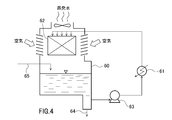
セル12A~12C及び試料水容器20に収容される試料水Wは、循環式冷却水系の循環水又は補給水である。図4に、循環式冷却水系の水の流れの一例を示す。図4に示すように、熱交換器61における熱交換により温度が上昇した水が冷却塔60に供給される。冷却塔60に供給された温水は充填材62を流下し、空気と向流接触して一部が蒸発する。蒸発潜熱によって冷却された水は冷却塔60の下部のピットに貯留され、ポンプ63により熱交換器61に供給される。ブロー水配管64のブロー弁(図示略)を開とすることによりブローが行われる。蒸発量とブロー水量との合計量に相当する補給水が補給水配管65からボールタップ(図示略)を介して冷却塔60に供給される。
冷却塔60のピット内の水、ポンプ63により熱交換器61に供給される水、又は熱交換器61から冷却塔60に供給される水、好ましくはピット内の水の一部を採取して、循環水の試料水とする。また、配管65から冷却塔60に供給される補給水の一部を採取して、補給水の試料水とする。
濃縮倍数測定装置の操作部4は、循環水モードと補給水モードとの切り替え設定を行う。循環水モードの設定時に吸光度測定部1、電極測定部2、電気伝導率測定部3により測定された値は、循環水の測定値としてメモリ7に記憶される。また、補給水モードの設定時に吸光度測定部1、電極測定部2、電気伝導率測定部3により測定された値は、補給水の測定値としてメモリ7に記憶される。
演算部6は、循環水モード設定時の測定値及び補給水モード設定時の測定値に基づいて、循環水中の塩類濃度が補給水と比較して何倍になっているかを示す指標である濃縮倍数を算出する。例えば、同一の溶存成分について、循環水モード設定時に測定された溶存成分濃度を補給水モード設定時に測定された溶存成分濃度で除算することで、濃縮倍数が算出される。また、例えば、循環水モード設定時に測定された電気伝導率を補給水モード設定時に測定された電気伝導率で除算することでも、濃縮倍数が算出される。
この実施の形態では、複数の濃縮倍数が取得される。即ち、セル12A~12Cの各吸光度から求めた溶存成分濃度に基づく濃縮倍数、イオン電極測定値により求めたイオン濃度に基づく濃縮倍数、電気伝導率に基づく濃縮倍数が算出される。
表示部5は、演算部6により算出された複数の濃縮倍数や、各測定部による測定値を表示する。メモリ7は、各測定部による測定値、検量線データ、演算部6により算出された複数の濃縮倍数などを記憶する。
次に、本実施形態による濃縮倍数測定方法を図5に示すフローチャートを用いて説明する。ここでは、補給水の測定を行った後に循環水の測定を行う場合について説明するが、循環水の測定を行った後に補給水の測定を行ってもよい。また、補給水については測定を行わず、過去に測定しメモリ7に記憶させている値を参照してもよい。
ステップS101:操作部4を用いて補給水モードを設定する。
ステップS102:採取した補給水を試料水容器20に収容し、筐体Hの容器配置部21に設置する。センサ設置盤15を倒伏させると、イオン電極16,17、pHガラス電極18、比較電極23、及び電気伝導率計19の下部が試料水容器20内の試料水に浸漬される。
ステップS103:採取した補給水をセル12A~12Cに収容し、発色試薬と十分に混合した後、差込穴13A~13Cに差し込んで設置する。
ステップS104:吸光度測定部1が吸光光度法により発色試薬が添加された試料水(この場合は補給水)の吸光度を測定する。メモリ7に記憶されている検量線を参照し、吸光度測定部1による測定値から、測定対象成分の溶存成分濃度を求める。
また、電極測定部2が、イオン電極法により試料水(補給水)中の測定対象イオン濃度を求め、ガラス電極法により試料水(補給水)のpHを測定する。さらに、電気伝導率測定部3が交流二電極法により試料水(補給水)の電気伝導率を求める。
ステップS105:ステップS104における測定値や算出値がメモリ7に記憶されるとともに、表示部5に表示される。その後、センサ設置盤15を起立させ、各測定機器を純水で洗浄する。また、試料水容器20及び各セル12A~12Cを取り出す。
ステップS106:操作部4を用いて補給水モードから循環水モードに設定を切り替える。
ステップS107:循環水系から採取した循環水を試料水容器20に収容し、容器配置部21に設置し、センサ設置盤15を倒伏させる。
ステップS108:循環水系から採取した循環水をセル12A~12Cに収容し、発色試薬と十分に混合した後、差込穴13A~13Cに差し込んで設置する。
ステップS109:吸光度測定部1が試料水(この場合は循環水)の吸光度を測定する。メモリ7に記憶されている検量線を参照し、吸光度測定部1による測定値から、測定対象成分の溶存成分濃度を求める。
また、電極測定部2が試料水(循環水)中の測定対象イオン濃度を求め、ガラス電極法により試料水(循環水)のpHを測定する。さらに、電気伝導率測定部3が試料水(循環水)の電気伝導率を求める。
ステップS110:ステップS109における測定値や算出値がメモリ7に記憶されるとともに、表示部5に表示される。
ステップS111:演算部6が、循環水モード設定時に測定された溶存成分濃度や電気伝導率等、及び補給水モード設定時に測定された溶存成分濃度や電気伝導率等をメモリ7から取り出し、除算することで、複数の濃縮倍数を算出する。算出された複数の濃縮倍数は、メモリ7に記憶されるとともに、表示部5に表示される。
このように、本実施形態では、異なる2種以上、より好ましくは3種以上の複数種類の水質特性値を測定し、複数の濃縮倍数を算出する。そのため、例えば、ある成分がスケールとして析出して、この成分の測定値に基づく濃縮倍数が誤差の大きい値となった場合でも、他の種類の水質の測定値から精度の高い濃縮倍数を得ることができる。2種の水質項目のみから濃縮倍数を算出する場合は、例えば、炭酸カルシウムスケールの生成が想定される酸消費量(pH4.8)とカルシウム硬度の組合せや、ケイ酸マグネシウムスケールの生成が想定されるシリカとマグネシウム硬度の組合せを避けるのが好ましい。この他にも、次亜塩素酸系のスライム防止剤を用いている系で塩化物イオンを用いた濃縮管理も不適である。このようにして得られた精度の高い濃縮倍数に基づいて、循環水系の濃縮管理を適切に行うことができる。
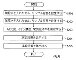
上記実施形態では、図1に示すように、濃縮倍数測定装置には、吸光度測定部1、電極測定部2、電気伝導率測定部3、センサ設置盤15、試料水容器20、試料水容器配置部21よりなる測定部セットが1セットのみ設けられていたが、この測定部セットを2又はそれ以上設けてもよい。この場合、試料水を入れ替えることなく、循環水の水質と補給水の水質を同時に測定することができる。また、操作部4に循環水モードと補給水モードとの設定切り替え機能は不要となる。循環水や補給水について2以上のサンプルを同時に並行して測定することもできる。このような濃縮倍数測定装置を用いた循環水及び補給水の同時測定方法を図6に示すフローチャートを用いて説明する。
ステップS201:循環水系に供給される補給水を採取してセル12A~12C、試料水容器20にそれぞれ収容し、一方の測定部セットに設置し、センサ設置盤15を倒伏させる。
ステップS202:循環水系から採取した循環水をセル12A~12C、試料水容器20にそれぞれ収容し、他方の測定部セットに設置し、該他方のセットのセンサ設置盤15を倒伏させる。
ステップS203:各測定部セットの吸光度測定部1が各試料水の吸光度を測定する。メモリ7に記憶されている検量線を参照し、吸光度測定部1による測定値から、循環水、補給水の各々について、測定対象成分の溶存成分濃度を求める。また、電極測定部2が各試料水中の測定対象イオン濃度やpHを求める。さらに、電気伝導率測定部3が各試料水の電気伝導率を求める。
ステップS204:ステップS203における測定値や算出値がメモリ7に記憶されるとともに、表示部5に表示される。
ステップS205:演算部6が、循環水の溶存成分濃度や電気伝導率等、及び補給水の溶存成分濃度や電気伝導率等をメモリ7から取り出し、除算することで、複数の濃縮倍数を算出する。算出された複数の濃縮倍数は、メモリ7に記憶されるとともに、表示部5に表示される。
このように、測定部セットを2以上設けることで、濃縮倍数を速やかに算出することができる。
上記実施形態においては、吸光度測定部1、電極測定部2及び電気伝導率測定部3を設置しているが、本発明では2種以上の水質項目について測定が行われるのであれば、これらのうちのいずれか1又は2を省略した構成としてもよい。このような構成としても、複数種類の水質項目の測定データから複数の濃縮倍数を求めることができる。
本発明では、演算部6は、吸光度測定部1により求められた酸消費量(pH4.8)、電極測定部2により求められたpH、カルシウム硬度、電気伝導率測定部3により求められた電気伝導率を用いて、循環水系のランゲリア指数(飽和指数)を算出してもよい。ランゲリア指数は、循環水のpHと炭酸カルシウムの飽和pH(pHs)との差であり、水系における配管や熱交換器等の金属材料の腐食性を測る指標となる。pHsは、簡便計算法(ノーデル法)により、以下の数式2で求められる。
pHs=(9.3+A値+B値)-(C値+D値) …(数式2)
ここで、A値は、蒸発残留物の濃度により定まる値であり、電気伝導率から求まる。B値は循環水の水温から定まる値である。C値は、カルシウム硬度により定まる値である。D値は、酸消費量(pH4.8)により定まる値である。
また、演算部6は、循環水のpHと炭酸カルシウムの飽和pH(pHs)とを用いて、以下の数式3により、水の腐食性とスケール生成の傾向の指標となるリズナー指数RSI(Ryznar Stability Index)を求めることができる。
RSI=2pHs-pH …(数式3)
RSIが6未満のとき水はスケール生成傾向にあることを示し、RSIが6以上7未満のとき水は安定状態にあることを示し、RSIが7以上のとき水は腐食傾向にあることを示す。
RSI=2pHs-pH …(数式3)
RSIが6未満のとき水はスケール生成傾向にあることを示し、RSIが6以上7未満のとき水は安定状態にあることを示し、RSIが7以上のとき水は腐食傾向にあることを示す。
また、演算部6は、吸光度測定部1により求められた硫酸イオン濃度、酸消費量(pH4.8)、及び酸消費量(pH8.3)を用いて、銅の孔食発生の指標となるマットソン比を求めることができる。マットソン比は水中の炭酸水素イオン濃度と硫酸イオン濃度の比([HCO3
-]/[SO4
2-])であり、炭酸水素イオン濃度HCO3
-(mgHCO3
-/L)は以下の数式4により求めることができる。
HCO3 -(mgHCO3 -/L)=1.22×(酸消費量(pH4.8)-2×酸消費量(pH8.3)) …(数式4)
マットソン比が1以下で、残留塩素が存在するとき、60℃程度の温水で、銅に孔食が生じやすいと判断される(出展:JRA-GL02(1994) (社)日本冷凍空調工業会)。
HCO3 -(mgHCO3 -/L)=1.22×(酸消費量(pH4.8)-2×酸消費量(pH8.3)) …(数式4)
マットソン比が1以下で、残留塩素が存在するとき、60℃程度の温水で、銅に孔食が生じやすいと判断される(出展:JRA-GL02(1994) (社)日本冷凍空調工業会)。
このように、本実施形態に係る濃縮倍数測定装置によれば、濃縮倍数を算出する過程で測定される値を用いて、ランゲリア指数、リズナー指数、マットソン比などの水質指標値を容易に算出することができる。
濃縮倍数測定装置により測定・算出された値はメモリ7に記憶されるため、これらの値を用いて表示部5にトレンド表示してもよい。
本発明では、濃縮倍数測定装置に通信部を設け、濃縮倍数測定装置により測定・算出された値をメモリ7から取り出し、外部サーバへ出力できるようにしてもよい。この通信部が有線/無線ネットワークを介してサーバへデータを送信してもよいし、通信部から有線/無線ネットワークを介してデータを受信したスマートフォン等の携帯端末がサーバへデータを送信してもよい。
上記実施の形態では、表示部5で循環水、補給水の表示と測定結果の表示とを行うようにしているが、各表示部を別々に設けてもよい。この場合、循環水、補給水の表示はランプで行ってもよい。また、音声で表示を行ってもよい。
[実施例1]
図1,2に示す濃縮倍数測定装置を用いて、モデルプラントに設置された循環水系の循環水及び補給水について、電気伝導率、カルシウム硬度、酸消費量(pH4.8)及びシリカ濃度を測定し、さらにそれぞれの測定値から濃縮倍数を算出した。なお、各セル12A~12Cの容積は4mL、酸消費量(pH4.8)測定用発色試薬としてブロモクレゾールグリーン、シリカ測定用発色試薬としてモリブデン酸アンモニウムを用いた。測定結果を以下の表1に示す。
図1,2に示す濃縮倍数測定装置を用いて、モデルプラントに設置された循環水系の循環水及び補給水について、電気伝導率、カルシウム硬度、酸消費量(pH4.8)及びシリカ濃度を測定し、さらにそれぞれの測定値から濃縮倍数を算出した。なお、各セル12A~12Cの容積は4mL、酸消費量(pH4.8)測定用発色試薬としてブロモクレゾールグリーン、シリカ測定用発色試薬としてモリブデン酸アンモニウムを用いた。測定結果を以下の表1に示す。

表1の通り、このモデルプラントでは、循環水および補給水のカルシウム硬度、酸消費量(pH4.8)、シリカ濃度のそれぞれから算出した濃縮倍数が、5.2~5.3倍と概ね同じであり、これらの値を平均して濃縮倍数を5.3倍と判断した。
一方、電気伝導率から算出した濃縮倍数は5.8倍と、溶存成分濃度から算出した濃縮倍数と比較すると、やや大きいものとなっていた。これは、薬品由来の電気伝導率の上昇があったためと考えられる。従って、このモデルプラントでは、溶存成分濃度に基づいて濃縮倍数を算出することが適切であることが認められた。
また、このモデルプラントでは、熱交換器の循環水出口温度が40℃、水質分析時の循環水のpHが8.7であったことから、ランゲリア指数が1.0と算出された。このことから、このモデルプラントの循環水系では、炭酸カルシウムの析出が起こりやすく、水の腐食傾向は小さいことが現場にて確認できた。
なお、この濃縮倍数測定装置を使用せずにランゲリア指数を算出する場合には、サンプル水の持ち帰り、分析(場合により水質分析会社への送付)、個別数値からのランゲリア指数の算出などの工程が必要となり、サンプルの採水からランゲリア指数の算出までに数日~1週間程度の日数を有する。そのため、算出されたランゲリア指数と、算出時点での実際のランゲリア指数とが異なり、循環水系を適切に管理できない。
本発明を特定の態様を用いて詳細に説明したが、本発明の意図と範囲を離れることなく様々な変更が可能であることは当業者に明らかである。
本出願は、2014年4月18日付で出願された日本特許出願2014-086543に基づいており、その全体が引用により援用される。
本出願は、2014年4月18日付で出願された日本特許出願2014-086543に基づいており、その全体が引用により援用される。
Claims (12)
- 試料水が循環水であるか補給水であるかを選択するための操作部と、
試料水の第1ないし第n(nは2以上の整数)の水質特性値を測定するための第1ないし第nの水質測定器と、
各水質測定器が循環水及び補給水についてそれぞれ測定した測定値に基づいて濃縮倍数を演算する演算部と、
を備える濃縮倍数測定装置。 - 請求項1において、前記水質測定器として、透過率又は吸光度を測定するための光学的測定器、1種又は2種のイオン電極、及び電気伝導率計のうちの少なくとも2個を備えたことを特徴とする濃縮倍数測定装置。
- 請求項1又は2において、前記操作部、第1ないし第nの水質測定器、及び演算部が一つの筐体に設置されていることを特徴とする濃縮倍数測定装置。
- 請求項3において、前記筐体に、光学的測定用のセルを差し込むための差込穴が設けられていることを特徴とする濃縮倍数測定装置。
- 請求項3又は4において、前記筐体に、操作部で選択された試料水が循環水であるか補給水であるかを表示する選択結果表示部が設けられていることを特徴とする濃縮倍数測定装置。
- 請求項3ないし5のいずれか1項において、水質測定結果及び濃縮倍数の演算結果のうち少なくとも濃縮倍数を表示する測定結果表示部が設けられていることを特徴とする濃縮倍数測定装置。
- 請求項6において、該濃縮倍数測定装置は、測定結果を記憶するメモリを備えており、前記測定結果表示部は、過去データを含めたトレンドを表示することを特徴とする濃縮倍数測定装置。
- 請求項3ないし7のいずれか1項において、前記筐体は、その上面部に、起倒方向に回動可能なセンサ設置盤が設けられ、該センサ設置盤の下面から突出するようにイオン電極又は電気伝導率計よりなる水質測定器が設置されており、
前記筐体には、倒伏状態の該センサ設置盤の下方に試料水用の容器が配置されており、
該センサ設置盤が倒伏した状態において、水質測定器の下端側が該容器内の試料水に浸漬されることを特徴とする濃縮倍数測定装置。 - 請求項1ないし8のいずれか1項において、前記第1ないし第nの水質測定器よりなる測定器セットを複数個備えていることを特徴とする濃縮倍数測定装置。
- 請求項1ないし9のいずれか1項の濃縮倍数測定装置を用いて循環水の濃縮倍数を演算することを特徴とする循環水の濃縮倍数測定方法。
- 請求項1ないし9のいずれか1項の濃縮倍数測定装置を用いて、循環水のpH、電気伝導率、カルシウム硬度及び酸消費量(pH4.8)を測定し、この測定結果よりランゲリア指数及びリズナー指数のうち少なくともいずれか一方を演算することを特徴とする循環水の水質指標値測定方法。
- 請求項1ないし9のいずれか1項の濃縮倍数測定装置を用いて、循環水の硫酸イオン濃度、酸消費量(pH4.8)及び酸消費量(pH8.3)を測定し、この測定結果よりマットソン比を演算することを特徴とする循環水の水質指標値測定方法。
Priority Applications (1)
| Application Number | Priority Date | Filing Date | Title |
|---|---|---|---|
| US15/304,762 US10041924B2 (en) | 2014-04-18 | 2015-04-01 | Concentration-factor measurement device and method |
Applications Claiming Priority (2)
| Application Number | Priority Date | Filing Date | Title |
|---|---|---|---|
| JP2014-086543 | 2014-04-18 | ||
| JP2014086543A JP5895967B2 (ja) | 2014-04-18 | 2014-04-18 | 濃縮倍数測定装置、濃縮倍数測定方法、及び水質指標値測定方法 |
Publications (1)
| Publication Number | Publication Date |
|---|---|
| WO2015159710A1 true WO2015159710A1 (ja) | 2015-10-22 |
Family
ID=54323921
Family Applications (1)
| Application Number | Title | Priority Date | Filing Date |
|---|---|---|---|
| PCT/JP2015/060318 Ceased WO2015159710A1 (ja) | 2014-04-18 | 2015-04-01 | 濃縮倍数測定装置、濃縮倍数測定方法、及び水質指標値測定方法 |
Country Status (3)
| Country | Link |
|---|---|
| US (1) | US10041924B2 (ja) |
| JP (1) | JP5895967B2 (ja) |
| WO (1) | WO2015159710A1 (ja) |
Cited By (3)
| Publication number | Priority date | Publication date | Assignee | Title |
|---|---|---|---|---|
| JP2017173131A (ja) * | 2016-03-24 | 2017-09-28 | 宇部興産株式会社 | 電気伝導率によるセメントの凝結始発時間算出方法 |
| CN109443987A (zh) * | 2018-11-29 | 2019-03-08 | 浙江工贸职业技术学院 | 一种带有比重计的废水监测方法及其装置 |
| CN109443972A (zh) * | 2018-11-29 | 2019-03-08 | 浙江工贸职业技术学院 | 一种带有电子天平的废水监测方法及其装置 |
Families Citing this family (8)
| Publication number | Priority date | Publication date | Assignee | Title |
|---|---|---|---|---|
| JP5895967B2 (ja) * | 2014-04-18 | 2016-03-30 | 栗田工業株式会社 | 濃縮倍数測定装置、濃縮倍数測定方法、及び水質指標値測定方法 |
| JP6720465B2 (ja) * | 2016-01-14 | 2020-07-08 | オプテックス株式会社 | 携帯型情報端末、携帯型情報端末の制御方法、および制御プログラム |
| KR102577173B1 (ko) * | 2016-11-07 | 2023-09-08 | 어플라이드 머티어리얼스, 인코포레이티드 | 반도체 챔버 부품들로부터의 나노입자들의 검출 및 분석을 위한 방법들 및 장치 |
| TWI629463B (zh) * | 2017-10-12 | 2018-07-11 | 捷騰光電股份有限公司 | Water quality sensor |
| JP7135310B2 (ja) * | 2017-12-05 | 2022-09-13 | 栗田工業株式会社 | 基板洗浄機のリンス排水の振り分け方法及び振り分け装置 |
| DE102018103530A1 (de) * | 2018-02-16 | 2019-08-22 | Endress+Hauser Conducta Gmbh+Co. Kg | Analysegerät zur Bestimmung einer eine Silikatkonzentration in einer Probenflüssigkeit repräsentierenden Messgröße |
| USD954002S1 (en) * | 2020-07-02 | 2022-06-07 | Thermo Orion Inc. | Controller |
| CN114236068B (zh) * | 2021-11-24 | 2024-03-01 | 中冶赛迪信息技术(重庆)有限公司 | 一种基于循环水系统的氯离子浓度分析方法及系统 |
Citations (8)
| Publication number | Priority date | Publication date | Assignee | Title |
|---|---|---|---|---|
| JPH03288586A (ja) * | 1990-04-04 | 1991-12-18 | Kurita Water Ind Ltd | 水系の汚れのモニタリング方法 |
| JPH06262198A (ja) * | 1989-11-21 | 1994-09-20 | Takeo Oe | 循環水路系の水質管理方法及び水質管理表 |
| JP2001062263A (ja) * | 1999-08-27 | 2001-03-13 | Hitachi Plant Eng & Constr Co Ltd | 膜モジュールの漏洩検知装置 |
| JP2001205249A (ja) * | 2000-01-24 | 2001-07-31 | Ffc:Kk | 水質管理サービス提供システム |
| JP2007128440A (ja) * | 2005-11-07 | 2007-05-24 | Kurita Water Ind Ltd | 水処理プラントの運転管理装置 |
| JP2007256147A (ja) * | 2006-03-24 | 2007-10-04 | Kaken:Kk | モバイル型マイクロ計測器 |
| JP2008058148A (ja) * | 2006-08-31 | 2008-03-13 | Dkk Toa Corp | 小型分析装置 |
| JP2014228488A (ja) * | 2013-05-24 | 2014-12-08 | 東亜ディーケーケー株式会社 | 水質検査装置 |
Family Cites Families (12)
| Publication number | Priority date | Publication date | Assignee | Title |
|---|---|---|---|---|
| JP2002210454A (ja) | 2001-01-19 | 2002-07-30 | Japan Organo Co Ltd | 冷却水系における水処理用薬品の濃度管理方法及び装置 |
| US6780307B2 (en) * | 2001-10-12 | 2004-08-24 | The United States Of America As Represented By The Secretary Of The Navy | Ion selective electrodes for direct organic drug analysis in saliva, sweat, and surface wipes |
| WO2008058148A2 (en) * | 2006-11-06 | 2008-05-15 | Kronos Advanced Technologies, Inc. | Desalination method and device |
| KR100749318B1 (ko) * | 2006-12-19 | 2007-08-14 | 세창인스트루먼트(주) | 수도관의 최적의 수질측정 및 알림장치 및 그 방법 |
| US7702473B2 (en) * | 2007-04-17 | 2010-04-20 | The United States Of America As Represented By The Secretary Of The Army | Submersible portable in-situ automated water quality biomonitoring apparatus and method |
| US20090123340A1 (en) * | 2007-05-04 | 2009-05-14 | H2Observe, Llc | Water quality monitoring device and method |
| US8951472B2 (en) * | 2010-07-19 | 2015-02-10 | Andalyze, Inc. | Portable fluorimetric apparatus, method and system |
| JP5790749B2 (ja) * | 2013-12-10 | 2015-10-07 | 栗田工業株式会社 | 水処理薬品濃度算出システム及び方法 |
| KR101593450B1 (ko) * | 2014-02-10 | 2016-02-12 | 손윤호 | 펜 방식의 복합 수질측정장치 |
| JP5895967B2 (ja) * | 2014-04-18 | 2016-03-30 | 栗田工業株式会社 | 濃縮倍数測定装置、濃縮倍数測定方法、及び水質指標値測定方法 |
| TWI567390B (zh) * | 2016-02-16 | 2017-01-21 | Solteam Opto Inc | Can be automated production of water quality sensor |
| BR112018067880B1 (pt) * | 2016-03-07 | 2022-11-22 | Ysi, Inc | Sensor óptico de nitrato e método para a medição de multiparâmetros da qualidade de água |
-
2014
- 2014-04-18 JP JP2014086543A patent/JP5895967B2/ja not_active Expired - Fee Related
-
2015
- 2015-04-01 WO PCT/JP2015/060318 patent/WO2015159710A1/ja not_active Ceased
- 2015-04-01 US US15/304,762 patent/US10041924B2/en not_active Expired - Fee Related
Patent Citations (8)
| Publication number | Priority date | Publication date | Assignee | Title |
|---|---|---|---|---|
| JPH06262198A (ja) * | 1989-11-21 | 1994-09-20 | Takeo Oe | 循環水路系の水質管理方法及び水質管理表 |
| JPH03288586A (ja) * | 1990-04-04 | 1991-12-18 | Kurita Water Ind Ltd | 水系の汚れのモニタリング方法 |
| JP2001062263A (ja) * | 1999-08-27 | 2001-03-13 | Hitachi Plant Eng & Constr Co Ltd | 膜モジュールの漏洩検知装置 |
| JP2001205249A (ja) * | 2000-01-24 | 2001-07-31 | Ffc:Kk | 水質管理サービス提供システム |
| JP2007128440A (ja) * | 2005-11-07 | 2007-05-24 | Kurita Water Ind Ltd | 水処理プラントの運転管理装置 |
| JP2007256147A (ja) * | 2006-03-24 | 2007-10-04 | Kaken:Kk | モバイル型マイクロ計測器 |
| JP2008058148A (ja) * | 2006-08-31 | 2008-03-13 | Dkk Toa Corp | 小型分析装置 |
| JP2014228488A (ja) * | 2013-05-24 | 2014-12-08 | 東亜ディーケーケー株式会社 | 水質検査装置 |
Non-Patent Citations (1)
| Title |
|---|
| SHIN'ICHI TAKASAKI: "Kucho Setsubi-yo Haikankei no Boshoku to Kanri 3. Corrosion and Water Quality", REFRIGERATION, vol. 77, no. 897, 2002, pages 577 - 583 * |
Cited By (3)
| Publication number | Priority date | Publication date | Assignee | Title |
|---|---|---|---|---|
| JP2017173131A (ja) * | 2016-03-24 | 2017-09-28 | 宇部興産株式会社 | 電気伝導率によるセメントの凝結始発時間算出方法 |
| CN109443987A (zh) * | 2018-11-29 | 2019-03-08 | 浙江工贸职业技术学院 | 一种带有比重计的废水监测方法及其装置 |
| CN109443972A (zh) * | 2018-11-29 | 2019-03-08 | 浙江工贸职业技术学院 | 一种带有电子天平的废水监测方法及其装置 |
Also Published As
| Publication number | Publication date |
|---|---|
| JP5895967B2 (ja) | 2016-03-30 |
| JP2015205236A (ja) | 2015-11-19 |
| US10041924B2 (en) | 2018-08-07 |
| US20170038358A1 (en) | 2017-02-09 |
Similar Documents
| Publication | Publication Date | Title |
|---|---|---|
| JP5895967B2 (ja) | 濃縮倍数測定装置、濃縮倍数測定方法、及び水質指標値測定方法 | |
| JP6202135B2 (ja) | 水質管理装置 | |
| WO2015159711A1 (ja) | 水質管理装置、水質管理システム、及び水質管理方法 | |
| Pawlowicz et al. | Metrological challenges for measurements of key climatological observables Part 2: oceanic salinity | |
| JPWO2013065207A1 (ja) | 防食性能劣化検知センサー並びに給湯暖房システム及び設備機器 | |
| WO2012082061A1 (en) | Method for predicting the conductivity of a liquid mixture | |
| Harned et al. | The properties of electrolytes in mixtures of water and organic solvents. II. Ionization constant of water in 20, 45 and 70% dioxane-water mixtures | |
| KR100874779B1 (ko) | 감응부가 평편한 수소이온농도 측정복합센서 | |
| Lisak et al. | Multicalibrational procedure for more reliable analyses of ions at low analyte concentrations | |
| WO2019191610A1 (en) | Apparatus for measuring water hardness using ion selective electrode | |
| KR100428751B1 (ko) | 티디에스/염분 측정기 | |
| Postolache et al. | Greenhouse environment: Air and water monitoring | |
| Palmer et al. | Isopiestic determination of the osmotic and activity coefficients of K2SO4 (aq) at the temperatures 298.15 and 323.15 K, and revision of the thermodynamic properties of the K2SO4+ H2O system | |
| Dash et al. | New data on activity coefficients of potassium, nitrate, and chloride ions in aqueous solutions of KNO3 and KCl by ion selective electrodes | |
| Tomlinson et al. | Potentiometric system for the continuous determination of low levels of chloride in high-purity power station waters | |
| Zhong et al. | Mean activity coefficients of NaBr in NaBr+ Na2SO4+ H2O ternary system at 298.15 K determined by potential difference measurements | |
| Dole et al. | The theory of the glass electrode. IV. Temperature studies of the glass electrode error | |
| CN201740741U (zh) | 便携式多功能比色仪 | |
| JP2012117954A (ja) | フッ化水素検出装置 | |
| Gangar et al. | Emerging Role of Internet of Things (IoT) for Wastewater Management: Sensing, Treatment and Process Optimization | |
| KR101600368B1 (ko) | 시험지를 이용한 선택성 이온측정기 | |
| Akilan | Thermodynamic and related studies of aqueous copper (II) sulfate solutions | |
| Beck et al. | Novel Bare Amperometric Sensors to Provide Accurate Stabilized Bromine Dosing in Cooling Towers | |
| JP2004340803A (ja) | 赤外分析測定用セルおよびそれを用いた測定方法 | |
| JP3401387B2 (ja) | 溶液組成測定システム |
Legal Events
| Date | Code | Title | Description |
|---|---|---|---|
| 121 | Ep: the epo has been informed by wipo that ep was designated in this application |
Ref document number: 15780202 Country of ref document: EP Kind code of ref document: A1 |
|
| WWE | Wipo information: entry into national phase |
Ref document number: 15304762 Country of ref document: US |
|
| NENP | Non-entry into the national phase |
Ref country code: DE |
|
| 122 | Ep: pct application non-entry in european phase |
Ref document number: 15780202 Country of ref document: EP Kind code of ref document: A1 |