WO2015155802A1 - Compresseur à volutes - Google Patents
Compresseur à volutes Download PDFInfo
- Publication number
- WO2015155802A1 WO2015155802A1 PCT/JP2014/002017 JP2014002017W WO2015155802A1 WO 2015155802 A1 WO2015155802 A1 WO 2015155802A1 JP 2014002017 W JP2014002017 W JP 2014002017W WO 2015155802 A1 WO2015155802 A1 WO 2015155802A1
- Authority
- WO
- WIPO (PCT)
- Prior art keywords
- scroll
- frame
- thrust
- orbiting scroll
- orbiting
- Prior art date
Links
- 239000000463 material Substances 0.000 claims abstract description 12
- 229910001018 Cast iron Inorganic materials 0.000 claims abstract description 7
- 229910000831 Steel Inorganic materials 0.000 claims abstract description 7
- 239000010959 steel Substances 0.000 claims abstract description 7
- 230000006835 compression Effects 0.000 claims description 9
- 238000007906 compression Methods 0.000 claims description 9
- 230000002093 peripheral effect Effects 0.000 claims description 9
- 239000003921 oil Substances 0.000 description 20
- 239000010687 lubricating oil Substances 0.000 description 14
- 239000003507 refrigerant Substances 0.000 description 12
- 230000000694 effects Effects 0.000 description 3
- 230000007246 mechanism Effects 0.000 description 2
- 238000000034 method Methods 0.000 description 2
- 229910000897 Babbitt (metal) Inorganic materials 0.000 description 1
- 238000010586 diagram Methods 0.000 description 1
- 238000007599 discharging Methods 0.000 description 1
- 238000006073 displacement reaction Methods 0.000 description 1
- XLYOFNOQVPJJNP-UHFFFAOYSA-N water Substances O XLYOFNOQVPJJNP-UHFFFAOYSA-N 0.000 description 1
- 238000004804 winding Methods 0.000 description 1
Images


Classifications
-
- F—MECHANICAL ENGINEERING; LIGHTING; HEATING; WEAPONS; BLASTING
- F04—POSITIVE - DISPLACEMENT MACHINES FOR LIQUIDS; PUMPS FOR LIQUIDS OR ELASTIC FLUIDS
- F04C—ROTARY-PISTON, OR OSCILLATING-PISTON, POSITIVE-DISPLACEMENT MACHINES FOR LIQUIDS; ROTARY-PISTON, OR OSCILLATING-PISTON, POSITIVE-DISPLACEMENT PUMPS
- F04C29/00—Component parts, details or accessories of pumps or pumping installations, not provided for in groups F04C18/00 - F04C28/00
- F04C29/02—Lubrication; Lubricant separation
- F04C29/023—Lubricant distribution through a hollow driving shaft
-
- F—MECHANICAL ENGINEERING; LIGHTING; HEATING; WEAPONS; BLASTING
- F01—MACHINES OR ENGINES IN GENERAL; ENGINE PLANTS IN GENERAL; STEAM ENGINES
- F01C—ROTARY-PISTON OR OSCILLATING-PISTON MACHINES OR ENGINES
- F01C17/00—Arrangements for drive of co-operating members, e.g. for rotary piston and casing
- F01C17/06—Arrangements for drive of co-operating members, e.g. for rotary piston and casing using cranks, universal joints or similar elements
- F01C17/066—Arrangements for drive of co-operating members, e.g. for rotary piston and casing using cranks, universal joints or similar elements with an intermediate piece sliding along perpendicular axes, e.g. Oldham coupling
-
- F—MECHANICAL ENGINEERING; LIGHTING; HEATING; WEAPONS; BLASTING
- F04—POSITIVE - DISPLACEMENT MACHINES FOR LIQUIDS; PUMPS FOR LIQUIDS OR ELASTIC FLUIDS
- F04C—ROTARY-PISTON, OR OSCILLATING-PISTON, POSITIVE-DISPLACEMENT MACHINES FOR LIQUIDS; ROTARY-PISTON, OR OSCILLATING-PISTON, POSITIVE-DISPLACEMENT PUMPS
- F04C18/00—Rotary-piston pumps specially adapted for elastic fluids
- F04C18/02—Rotary-piston pumps specially adapted for elastic fluids of arcuate-engagement type, i.e. with circular translatory movement of co-operating members, each member having the same number of teeth or tooth-equivalents
- F04C18/0207—Rotary-piston pumps specially adapted for elastic fluids of arcuate-engagement type, i.e. with circular translatory movement of co-operating members, each member having the same number of teeth or tooth-equivalents both members having co-operating elements in spiral form
- F04C18/0215—Rotary-piston pumps specially adapted for elastic fluids of arcuate-engagement type, i.e. with circular translatory movement of co-operating members, each member having the same number of teeth or tooth-equivalents both members having co-operating elements in spiral form where only one member is moving
-
- F—MECHANICAL ENGINEERING; LIGHTING; HEATING; WEAPONS; BLASTING
- F04—POSITIVE - DISPLACEMENT MACHINES FOR LIQUIDS; PUMPS FOR LIQUIDS OR ELASTIC FLUIDS
- F04C—ROTARY-PISTON, OR OSCILLATING-PISTON, POSITIVE-DISPLACEMENT MACHINES FOR LIQUIDS; ROTARY-PISTON, OR OSCILLATING-PISTON, POSITIVE-DISPLACEMENT PUMPS
- F04C29/00—Component parts, details or accessories of pumps or pumping installations, not provided for in groups F04C18/00 - F04C28/00
- F04C29/0042—Driving elements, brakes, couplings, transmissions specially adapted for pumps
- F04C29/005—Means for transmitting movement from the prime mover to driven parts of the pump, e.g. clutches, couplings, transmissions
- F04C29/0057—Means for transmitting movement from the prime mover to driven parts of the pump, e.g. clutches, couplings, transmissions for eccentric movement
-
- F—MECHANICAL ENGINEERING; LIGHTING; HEATING; WEAPONS; BLASTING
- F04—POSITIVE - DISPLACEMENT MACHINES FOR LIQUIDS; PUMPS FOR LIQUIDS OR ELASTIC FLUIDS
- F04C—ROTARY-PISTON, OR OSCILLATING-PISTON, POSITIVE-DISPLACEMENT MACHINES FOR LIQUIDS; ROTARY-PISTON, OR OSCILLATING-PISTON, POSITIVE-DISPLACEMENT PUMPS
- F04C29/00—Component parts, details or accessories of pumps or pumping installations, not provided for in groups F04C18/00 - F04C28/00
- F04C29/0042—Driving elements, brakes, couplings, transmissions specially adapted for pumps
- F04C29/005—Means for transmitting movement from the prime mover to driven parts of the pump, e.g. clutches, couplings, transmissions
- F04C29/0071—Couplings between rotors and input or output shafts acting by interengaging or mating parts, i.e. positive coupling of rotor and shaft
-
- F—MECHANICAL ENGINEERING; LIGHTING; HEATING; WEAPONS; BLASTING
- F04—POSITIVE - DISPLACEMENT MACHINES FOR LIQUIDS; PUMPS FOR LIQUIDS OR ELASTIC FLUIDS
- F04C—ROTARY-PISTON, OR OSCILLATING-PISTON, POSITIVE-DISPLACEMENT MACHINES FOR LIQUIDS; ROTARY-PISTON, OR OSCILLATING-PISTON, POSITIVE-DISPLACEMENT PUMPS
- F04C29/00—Component parts, details or accessories of pumps or pumping installations, not provided for in groups F04C18/00 - F04C28/00
- F04C29/02—Lubrication; Lubricant separation
- F04C29/025—Lubrication; Lubricant separation using a lubricant pump
-
- F—MECHANICAL ENGINEERING; LIGHTING; HEATING; WEAPONS; BLASTING
- F04—POSITIVE - DISPLACEMENT MACHINES FOR LIQUIDS; PUMPS FOR LIQUIDS OR ELASTIC FLUIDS
- F04C—ROTARY-PISTON, OR OSCILLATING-PISTON, POSITIVE-DISPLACEMENT MACHINES FOR LIQUIDS; ROTARY-PISTON, OR OSCILLATING-PISTON, POSITIVE-DISPLACEMENT PUMPS
- F04C29/00—Component parts, details or accessories of pumps or pumping installations, not provided for in groups F04C18/00 - F04C28/00
- F04C29/02—Lubrication; Lubricant separation
- F04C29/028—Means for improving or restricting lubricant flow
-
- F—MECHANICAL ENGINEERING; LIGHTING; HEATING; WEAPONS; BLASTING
- F04—POSITIVE - DISPLACEMENT MACHINES FOR LIQUIDS; PUMPS FOR LIQUIDS OR ELASTIC FLUIDS
- F04C—ROTARY-PISTON, OR OSCILLATING-PISTON, POSITIVE-DISPLACEMENT MACHINES FOR LIQUIDS; ROTARY-PISTON, OR OSCILLATING-PISTON, POSITIVE-DISPLACEMENT PUMPS
- F04C2240/00—Components
- F04C2240/10—Stators
-
- F—MECHANICAL ENGINEERING; LIGHTING; HEATING; WEAPONS; BLASTING
- F04—POSITIVE - DISPLACEMENT MACHINES FOR LIQUIDS; PUMPS FOR LIQUIDS OR ELASTIC FLUIDS
- F04C—ROTARY-PISTON, OR OSCILLATING-PISTON, POSITIVE-DISPLACEMENT MACHINES FOR LIQUIDS; ROTARY-PISTON, OR OSCILLATING-PISTON, POSITIVE-DISPLACEMENT PUMPS
- F04C2240/00—Components
- F04C2240/20—Rotors
-
- F—MECHANICAL ENGINEERING; LIGHTING; HEATING; WEAPONS; BLASTING
- F04—POSITIVE - DISPLACEMENT MACHINES FOR LIQUIDS; PUMPS FOR LIQUIDS OR ELASTIC FLUIDS
- F04C—ROTARY-PISTON, OR OSCILLATING-PISTON, POSITIVE-DISPLACEMENT MACHINES FOR LIQUIDS; ROTARY-PISTON, OR OSCILLATING-PISTON, POSITIVE-DISPLACEMENT PUMPS
- F04C2240/00—Components
- F04C2240/30—Casings or housings
-
- F—MECHANICAL ENGINEERING; LIGHTING; HEATING; WEAPONS; BLASTING
- F04—POSITIVE - DISPLACEMENT MACHINES FOR LIQUIDS; PUMPS FOR LIQUIDS OR ELASTIC FLUIDS
- F04C—ROTARY-PISTON, OR OSCILLATING-PISTON, POSITIVE-DISPLACEMENT MACHINES FOR LIQUIDS; ROTARY-PISTON, OR OSCILLATING-PISTON, POSITIVE-DISPLACEMENT PUMPS
- F04C2240/00—Components
- F04C2240/60—Shafts
- F04C2240/603—Shafts with internal channels for fluid distribution, e.g. hollow shaft
-
- F—MECHANICAL ENGINEERING; LIGHTING; HEATING; WEAPONS; BLASTING
- F04—POSITIVE - DISPLACEMENT MACHINES FOR LIQUIDS; PUMPS FOR LIQUIDS OR ELASTIC FLUIDS
- F04C—ROTARY-PISTON, OR OSCILLATING-PISTON, POSITIVE-DISPLACEMENT MACHINES FOR LIQUIDS; ROTARY-PISTON, OR OSCILLATING-PISTON, POSITIVE-DISPLACEMENT PUMPS
- F04C23/00—Combinations of two or more pumps, each being of rotary-piston or oscillating-piston type, specially adapted for elastic fluids; Pumping installations specially adapted for elastic fluids; Multi-stage pumps specially adapted for elastic fluids
- F04C23/008—Hermetic pumps
Definitions
- This invention mainly relates to a scroll compressor mounted on a refrigerant circuit such as a refrigerator, an air conditioner, or a water heater.
- a thrust bearing is known.
- an oil supply hole that leads from the boss part of the orbiting scroll to the thrust surface of the orbiting scroll is provided to increase the amount of oil supply.
- a thrust bearing surface that supports the orbiting scroll is formed with a plurality of spiral grooved mechanisms or a plurality of tapered land bearing mechanisms to generate oil film pressure and improve the wear resistance of the thrust bearing section.
- Japanese Unexamined Patent Publication No. 5-149277 paragraphs [0011] to [0016], FIG. 1
- Japanese Patent Laid-Open No. 8-319959 paragraphs [0018] to [0039], FIGS. 1 to 3
- the conventional thrust bearing configuration is a simple one that slides a rocking scroll made of cast iron and a thrust plate made of Swedish steel, etc., and does not use a bimetallic material thrust bearing. There has been a problem that the sliding property of the orbiting scroll and the thrust plate is deteriorated and the back surface (lower surface) of the orbiting scroll is worn or seized.
- the present invention has been made to solve the above-described problems, and wears and seizes the lower surface of the orbiting scroll despite the simple configuration not using an expensive bimetallic material thrust bearing. It aims at obtaining the scroll compressor which can be suppressed.
- the scroll compressor according to the present invention includes a main body container that is a hermetically sealed container, a fixed scroll fixed to an upper portion in the main body container, and a lower chamber in the center of the lower surface that is disposed below the fixed scroll to form a compression chamber together with the fixed scroll
- An orbiting scroll made of cast iron material having a boss portion on the top and an eccentric shaft portion that is rotatably supported by the oscillating bearing of the boss portion of the orbiting scroll is formed at the upper end portion, and communicates vertically within the shaft.
- a rotary drive shaft having an oil passage hole, a thrust support surface that receives the orbiting scroll, a recess that is formed on the inner side in the container radial direction from the thrust support surface and that houses the boss portion of the orbiting scroll, and a lower portion of the recess
- a frame having a main bearing portion that rotatably supports the rotary drive shaft and fixed to the inner peripheral surface of the main body container, a lower surface of the orbiting scroll, a thrust support surface of the frame, Ring plate-shaped thrust plate made of steel plate material that is slidably supported on the lower surface of the orbiting scroll, and accommodated in the recess of the frame to rotate around the rotation drive axis of the orbiting scroll
- An Oldham ring to be controlled and an Oldham groove on the lower side of the orbiting scroll formed on the lower surface of the orbiting scroll to guide the Oldham ring outside the boss portion.
- a circumferential groove communicating with the groove is formed.
- a circumferential groove communicating with the rocking-side Oldham groove is formed on the lower surface of the rocking scroll, so that a sufficient amount of lubricating oil is supplied between the rocking scroll and the thrust plate.
- the oil film pressure due to the wedge effect can be generated. As a result, it is possible to prevent wear on the lower surface of the orbiting scroll and to suppress seizure.
- FIG. 1A is a plan view
- FIG. 2B is a cross-sectional view taken along line BB in FIG.
- FIG. 1A is a plan view
- FIG. 2B is a cross-sectional view taken along line BB in FIG.
- FIG. 1A is a plan view
- FIG. 2B is a cross-sectional view taken along line BB in FIG.
- FIG. 1A is a plan view
- FIG. 2B is a cross-sectional view taken along line BB in FIG.
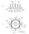
- FIG. 1 is a longitudinal sectional view of a scroll compressor according to Embodiment 1 of the present invention
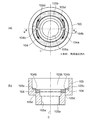
- FIG. 2 is a view showing a swing scroll of the scroll compressor
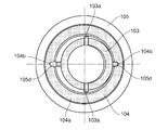
- FIG. 3 is a view showing a frame of the scroll compressor
- FIG. It is a top view which shows the state which mounted
- the scroll compressor according to this embodiment sucks the refrigerant circulating in the refrigerant circuit, compresses it into a high-temperature and high-pressure state, and discharges it to the refrigerant circuit.
- the scroll compressor includes a main body container 100 which is a hermetic container, a fixed scroll 101 fixedly disposed at an upper portion of the main body container 100, and an orbiting scroll disposed below the fixed scroll 101 and having a boss portion 102c on a lower surface. 102, a rotary drive shaft 114 having an oil passage hole 114 a communicating vertically with the inside of the shaft, a frame 105 fixedly arranged on the inner peripheral surface of the intermediate container of the main body container 100, and the swing scroll 102 slidably.
- a ring plate-like thrust plate 104 to be supported and an oil pump 108 connected to the lower portion of the rotary drive shaft 114 are provided.
- a discharge pipe 113 for discharging refrigerant gas is connected to the upper part of the main body container 100, and a suction pipe 112 for sucking refrigerant gas is connected to the trunk of the main body container 100.
- the oil pump 108 pumps up the lubricating oil (refrigerating oil) 109 accumulated at the bottom of the main body container 100 and sends it to the oil passage hole 114a.
- the frame 105 includes a thrust support surface 105c that supports the orbiting scroll 102, a recess 105b that is formed on the inner side in the container radial direction of the thrust support surface 105c and accommodates the boss portion 102c of the orbiting scroll 102, and It has a main bearing portion 105a that is formed in the lower portion of the recess 105b and rotatably supports the rotary drive shaft 114.
- An eccentric shaft portion 110 that is rotatably supported by the rocking bearing 102a of the boss portion 102c of the rocking scroll 102 is formed at the upper end portion of the rotation drive shaft 114.
- an Oldham ring 103 that restricts the rotation of the rotary drive shaft 114 around the axis C of the orbiting scroll 102 is housed in the recess 105 b of the frame 105.
- a frame-side Oldham groove 105d for guiding the Oldham ring 103 is formed to extend long in the radial direction (see FIGS. 3 and 4).
- a thrust plate 104 made of a steel plate material that slidably supports the orbiting scroll 102 is disposed.
- a notch 104b communicating with the frame-side Oldham groove 105d is formed in the thrust plate 104 at a position facing the frame-side Oldham groove 105d.
- the notch 104b is formed in a slightly larger shape than the frame-side Oldham groove 105d.
- the rocking scroll 102 and the thrust plate 104 are brought into close contact with each other via the lubricating oil 109 to constitute a thrust bearing portion.
- the thrust plate 104 also has a function of adjusting the clearance in the direction of the rotational drive axis C in the compression chamber 111.
- the fixed scroll 101 is formed with spiral teeth 101a erected on the lower surface (back surface) of the base plate.
- the swing scroll 102 is also provided with spiral teeth 102b that are erected on the upper surface of the base plate and have substantially the same shape as the spiral teeth 101a.
- the orbiting scroll 102 and the fixed scroll 101 are made of cast iron material, and are mounted in the main body container 100 in a state where the spiral teeth 102b and the spiral teeth 101a are combined with each other. In a state where the swing scroll 102 and the fixed scroll 101 are combined, the winding directions of the spiral teeth 101a and the spiral teeth 102b are opposite to each other.
- a compression chamber 111 whose volume changes relatively is formed between the spiral tooth 10a and the spiral tooth 9a.
- the fixed scroll 101 is fixed to the opening edge of the upper surface of the frame 105 with a bolt or the like (not shown).
- a hollow cylindrical boss portion 102c is suspended substantially at the center of the bottom surface of the orbiting scroll 102, and the inner peripheral surface of the boss portion 102c is an orbiting bearing 102a.
- an oscillating-side Oldham groove 102d that guides the upper surface protrusion 103a of the Oldham ring 103 is formed long in the radial direction at an outer position of the boss portion 102c on the lower surface of the oscillating scroll 102 (see FIG. 2).
- the rocking scroll 102 performs a revolving orbiting motion (so-called rocking motion) without performing the rotational motion with respect to the fixed scroll 101 by the Oldham ring 103 for preventing the rotational motion.
- An eccentric shaft portion 110 provided at the upper end of the rotary drive shaft 114 is rotatably inserted into the rocking bearing 102a.
- the inner peripheral part of the rocking bearing 102a and the outer peripheral part of the eccentric shaft part 110 are slidably brought into close contact with each other via the lubricating oil 109 to constitute the rocking bearing part.
- the electric motor 115 includes a rotor 106 fixed to the rotation drive shaft 114 and a stator 107 fixed to the inner peripheral surface of the intermediate container. The rotor 106 is driven to rotate when energization to the stator 107 is started, and rotates the rotation drive shaft 114.
- the rotation drive shaft 114 rotates with the rotation of the rotor 106 to rotate the swing scroll 102.
- the upper portion (position near the eccentric shaft portion 10) of the rotation drive shaft 114 is supported by a main bearing portion 105a provided on the frame 105.
- a ball bearing 117 is attached to the central portion of the sub-frame 116 fixed to the lower inner peripheral surface of the main body container 100, and the lower portion of the rotation drive shaft 114 is rotatably supported by the ball bearing 117.
- a positive displacement oil pump 108 is attached to the subframe 116.
- the oil pump 108 is connected to the rotary drive shaft 4 and receives a rotational force.
- the lubricating oil 109 sucked by the oil pump 108 is sent to each sliding portion through the oil passage hole 114a of the rotary drive shaft 114 and the like.
- the compression chamber 111 gradually moves to the center of the orbiting scroll 102 by the orbiting motion of the orbiting scroll 102, and the volume is further reduced. Through this process, the refrigerant gas sucked into the compression chamber 111 is compressed. At this time, a load that moves away from the fixed scroll 101 in the direction of the axis C is applied to the orbiting scroll 102 by the compressed refrigerant gas, and this load is received by the upper surface 104 a of the thrust plate 104. The compressed refrigerant passes through the discharge port of the fixed scroll 101 and is discharged from the main body container 100 to the refrigerant circuit through the discharge pipe 25.
- the lubricating oil 109 sucked up to the eccentric shaft portion 110 by the oil pump 108 is generated between the sliding portion of the bearing metal of the orbiting scroll 102, the thrust surface 102e of the orbiting scroll 102, and the upper surface 104a of the thrust plate 104. Lubricate the sliding part. Thereafter, a part of the lubricating oil 109 rises from the outer peripheral edge of the orbiting scroll 102 and enters the compression chamber 111 to lubricate the sliding portions of the spiral teeth 101 a and the spiral teeth 102 b, and the rest downward from the frame 105. And return to the oil sump at the bottom of the main body container 100.
- the lubricating oil 109 flows from the rocking scroll Oldham groove 102d to the circumferential groove 102f each time the rocking scroll 102 reciprocates along the rocking Oldham groove 102d. A sufficient amount of lubricating oil 109 is supplied from the circumferential groove 102f to the thrust surface 102e. Further, since the thrust plate 104 has the notch 104b, the lubricating oil 109 is supplied from the frame-side Oldham groove 105d to the thrust surface 102e every time the Oldham ring 103 reciprocates along the frame-side Oldham groove 105d. A flow path is secured. In the prior art, the notch 104b as described above was not formed in the thrust plate, which caused an obstacle to supply of lubricating oil from the frame-side Oldham groove to the thrust surface.
- the supply amount of the lubricating oil 109 to the thrust surface 102e can be increased, and a large oil film pressure can be generated due to the wedge effect generated thereby. As a result, wear and seizure of the thrust surface 102e of the orbiting scroll 102 can be suppressed.
- Embodiment 2 the bottom surface of the orbiting scroll is formed on a horizontal surface without being inclined, but the scroll compressor of the present invention is not limited to this.
- Embodiment 2 in which the thrust surface 102g of the orbiting scroll 102A supported by the upper surface 104a of the thrust plate 104 is formed as an inclined surface that descends radially outward is also included in the present invention. It is.
Abstract
Priority Applications (5)
| Application Number | Priority Date | Filing Date | Title |
|---|---|---|---|
| US15/111,385 US20160348680A1 (en) | 2014-04-09 | 2014-04-09 | Scroll compressor |
| CN201480073390.3A CN105917120A (zh) | 2014-04-09 | 2014-04-09 | 涡旋压缩机 |
| EP14888621.1A EP3130805A4 (fr) | 2014-04-09 | 2014-04-09 | Compresseur à volutes |
| PCT/JP2014/002017 WO2015155802A1 (fr) | 2014-04-09 | 2014-04-09 | Compresseur à volutes |
| JP2016512489A JPWO2015155802A1 (ja) | 2014-04-09 | 2014-04-09 | スクロール圧縮機 |
Applications Claiming Priority (1)
| Application Number | Priority Date | Filing Date | Title |
|---|---|---|---|
| PCT/JP2014/002017 WO2015155802A1 (fr) | 2014-04-09 | 2014-04-09 | Compresseur à volutes |
Publications (1)
| Publication Number | Publication Date |
|---|---|
| WO2015155802A1 true WO2015155802A1 (fr) | 2015-10-15 |
Family
ID=54287408
Family Applications (1)
| Application Number | Title | Priority Date | Filing Date |
|---|---|---|---|
| PCT/JP2014/002017 WO2015155802A1 (fr) | 2014-04-09 | 2014-04-09 | Compresseur à volutes |
Country Status (5)
| Country | Link |
|---|---|
| US (1) | US20160348680A1 (fr) |
| EP (1) | EP3130805A4 (fr) |
| JP (1) | JPWO2015155802A1 (fr) |
| CN (1) | CN105917120A (fr) |
| WO (1) | WO2015155802A1 (fr) |
Cited By (2)
| Publication number | Priority date | Publication date | Assignee | Title |
|---|---|---|---|---|
| CN105889076A (zh) * | 2016-04-25 | 2016-08-24 | 广东美的暖通设备有限公司 | 涡旋压缩机的主机架及涡旋压缩机 |
| US10920774B2 (en) | 2016-03-31 | 2021-02-16 | Mitsubishi Electric Corporation | Scroll compressor and refrigeration cycle apparatus |
Families Citing this family (1)
| Publication number | Priority date | Publication date | Assignee | Title |
|---|---|---|---|---|
| CN112041561A (zh) * | 2018-04-27 | 2020-12-04 | 三菱电机株式会社 | 涡旋压缩机以及制冷循环装置 |
Citations (7)
| Publication number | Priority date | Publication date | Assignee | Title |
|---|---|---|---|---|
| JPS5746001A (en) * | 1980-09-03 | 1982-03-16 | Hitachi Ltd | Scroll fluid device |
| JPH04107494U (ja) * | 1991-01-31 | 1992-09-17 | 株式会社ゼクセル | スクロール流体機械 |
| JPH05149277A (ja) * | 1991-11-26 | 1993-06-15 | Mitsubishi Heavy Ind Ltd | 横置型密閉スクロール圧縮機 |
| JP2008144678A (ja) * | 2006-12-11 | 2008-06-26 | Mitsubishi Electric Corp | スクロール圧縮機 |
| JP2012067602A (ja) * | 2010-09-21 | 2012-04-05 | Valeo Japan Co Ltd | スクロール型圧縮機 |
| JP2012219749A (ja) * | 2011-04-12 | 2012-11-12 | Mitsubishi Electric Corp | スクロール圧縮機 |
| JP2012225257A (ja) * | 2011-04-20 | 2012-11-15 | Mitsubishi Electric Corp | スクロール圧縮機 |
Family Cites Families (7)
| Publication number | Priority date | Publication date | Assignee | Title |
|---|---|---|---|---|
| KR910002402B1 (ko) * | 1986-11-05 | 1991-04-22 | 미쓰비시전기 주식회사 | 스크롤압축기 |
| JPH0441987A (ja) * | 1990-06-06 | 1992-02-12 | Mitsubishi Electric Corp | スクロール圧縮機 |
| KR100360237B1 (ko) * | 1999-10-15 | 2002-11-08 | 엘지전자 주식회사 | 스크롤 압축기의 오일 공급구조 |
| KR20030012662A (ko) * | 2001-08-03 | 2003-02-12 | 엘지전자 주식회사 | 스크롤 압축기의 마모 방지 구조 |
| CN1566696A (zh) * | 2003-06-17 | 2005-01-19 | 乐金电子(天津)电器有限公司 | 涡旋式压缩机的十字滑环油供给构造 |
| US8007261B2 (en) * | 2006-12-28 | 2011-08-30 | Emerson Climate Technologies, Inc. | Thermally compensated scroll machine |
| CN101793250A (zh) * | 2009-11-28 | 2010-08-04 | 广东正力精密机械有限公司 | 改善十字销环供油的涡旋压缩机 |
-
2014
- 2014-04-09 CN CN201480073390.3A patent/CN105917120A/zh active Pending
- 2014-04-09 JP JP2016512489A patent/JPWO2015155802A1/ja active Pending
- 2014-04-09 US US15/111,385 patent/US20160348680A1/en not_active Abandoned
- 2014-04-09 WO PCT/JP2014/002017 patent/WO2015155802A1/fr active Application Filing
- 2014-04-09 EP EP14888621.1A patent/EP3130805A4/fr not_active Withdrawn
Patent Citations (7)
| Publication number | Priority date | Publication date | Assignee | Title |
|---|---|---|---|---|
| JPS5746001A (en) * | 1980-09-03 | 1982-03-16 | Hitachi Ltd | Scroll fluid device |
| JPH04107494U (ja) * | 1991-01-31 | 1992-09-17 | 株式会社ゼクセル | スクロール流体機械 |
| JPH05149277A (ja) * | 1991-11-26 | 1993-06-15 | Mitsubishi Heavy Ind Ltd | 横置型密閉スクロール圧縮機 |
| JP2008144678A (ja) * | 2006-12-11 | 2008-06-26 | Mitsubishi Electric Corp | スクロール圧縮機 |
| JP2012067602A (ja) * | 2010-09-21 | 2012-04-05 | Valeo Japan Co Ltd | スクロール型圧縮機 |
| JP2012219749A (ja) * | 2011-04-12 | 2012-11-12 | Mitsubishi Electric Corp | スクロール圧縮機 |
| JP2012225257A (ja) * | 2011-04-20 | 2012-11-15 | Mitsubishi Electric Corp | スクロール圧縮機 |
Non-Patent Citations (1)
| Title |
|---|
| See also references of EP3130805A4 * |
Cited By (3)
| Publication number | Priority date | Publication date | Assignee | Title |
|---|---|---|---|---|
| US10920774B2 (en) | 2016-03-31 | 2021-02-16 | Mitsubishi Electric Corporation | Scroll compressor and refrigeration cycle apparatus |
| CN105889076A (zh) * | 2016-04-25 | 2016-08-24 | 广东美的暖通设备有限公司 | 涡旋压缩机的主机架及涡旋压缩机 |
| CN105889076B (zh) * | 2016-04-25 | 2019-08-27 | 广东美的环境科技有限公司 | 涡旋压缩机的主机架及涡旋压缩机 |
Also Published As
| Publication number | Publication date |
|---|---|
| EP3130805A4 (fr) | 2018-01-10 |
| JPWO2015155802A1 (ja) | 2017-04-13 |
| EP3130805A1 (fr) | 2017-02-15 |
| US20160348680A1 (en) | 2016-12-01 |
| CN105917120A (zh) | 2016-08-31 |
Similar Documents
| Publication | Publication Date | Title |
|---|---|---|
| EP2390507B1 (fr) | Dégagements du palier de l'arbre d'un compresseur hermétique | |
| JP6305552B2 (ja) | スクロール圧縮機 | |
| WO2015155802A1 (fr) | Compresseur à volutes | |
| JP6328330B2 (ja) | スクロール圧縮機 | |
| WO2017002212A1 (fr) | Compresseur à volutes | |
| WO2015177851A1 (fr) | Compresseur à spirales | |
| JP6745913B2 (ja) | 圧縮機 | |
| JP6289686B2 (ja) | スクロール圧縮機 | |
| JP6192801B2 (ja) | 圧縮機 | |
| WO2017208455A1 (fr) | Compresseur à spirales | |
| JP6104396B2 (ja) | スクロール圧縮機 | |
| JP5100471B2 (ja) | ロータリ圧縮機 | |
| JP2009167954A (ja) | 密閉型圧縮機 | |
| JP6320575B2 (ja) | 電動圧縮機 | |
| JP6598881B2 (ja) | スクロール圧縮機 | |
| JP2012087711A (ja) | 密閉型圧縮機 | |
| JP6029517B2 (ja) | スクロール圧縮機 | |
| JP5773922B2 (ja) | スクロール圧縮機 | |
| JP5836845B2 (ja) | スクロール圧縮機 | |
| JP6869378B2 (ja) | ロータリ圧縮機 | |
| KR101698085B1 (ko) | 밀폐형 압축기 | |
| JP2008223506A (ja) | 密閉型圧縮機 | |
| WO2015155798A1 (fr) | Compresseur à spirales | |
| JP2015007409A (ja) | 密閉型圧縮機 |
Legal Events
| Date | Code | Title | Description |
|---|---|---|---|
| 121 | Ep: the epo has been informed by wipo that ep was designated in this application |
Ref document number: 14888621 Country of ref document: EP Kind code of ref document: A1 |
|
| ENP | Entry into the national phase |
Ref document number: 2016512489 Country of ref document: JP Kind code of ref document: A |
|
| REEP | Request for entry into the european phase |
Ref document number: 2014888621 Country of ref document: EP |
|
| WWE | Wipo information: entry into national phase |
Ref document number: 2014888621 Country of ref document: EP |
|
| WWE | Wipo information: entry into national phase |
Ref document number: 15111385 Country of ref document: US |
|
| NENP | Non-entry into the national phase |
Ref country code: DE |