WO2015151641A1 - Ensemble fonctionnel à cycle combiné, procédé de commande correspondant et dispositif de commande correspondant - Google Patents
Ensemble fonctionnel à cycle combiné, procédé de commande correspondant et dispositif de commande correspondant Download PDFInfo
- Publication number
- WO2015151641A1 WO2015151641A1 PCT/JP2015/054798 JP2015054798W WO2015151641A1 WO 2015151641 A1 WO2015151641 A1 WO 2015151641A1 JP 2015054798 W JP2015054798 W JP 2015054798W WO 2015151641 A1 WO2015151641 A1 WO 2015151641A1
- Authority
- WO
- WIPO (PCT)
- Prior art keywords
- opening
- steam
- stop mode
- mode
- output
- Prior art date
Links
- 238000000034 method Methods 0.000 title claims description 129
- 238000011084 recovery Methods 0.000 claims abstract description 28
- 239000007789 gas Substances 0.000 claims description 172
- 238000001816 cooling Methods 0.000 claims description 70
- 239000000567 combustion gas Substances 0.000 claims description 38
- 239000000446 fuel Substances 0.000 description 110
- 230000006870 function Effects 0.000 description 42
- 239000002184 metal Substances 0.000 description 10
- XLYOFNOQVPJJNP-UHFFFAOYSA-N water Substances O XLYOFNOQVPJJNP-UHFFFAOYSA-N 0.000 description 8
- 238000003780 insertion Methods 0.000 description 5
- 230000037431 insertion Effects 0.000 description 5
- 230000007423 decrease Effects 0.000 description 4
- 230000004913 activation Effects 0.000 description 3
- 239000007858 starting material Substances 0.000 description 3
- 238000010586 diagram Methods 0.000 description 2
- 238000007689 inspection Methods 0.000 description 2
- 230000000737 periodic effect Effects 0.000 description 2
- 230000008646 thermal stress Effects 0.000 description 2
- 230000003247 decreasing effect Effects 0.000 description 1
- 230000009977 dual effect Effects 0.000 description 1
- 238000004519 manufacturing process Methods 0.000 description 1
- 230000002093 peripheral effect Effects 0.000 description 1
- 230000009897 systematic effect Effects 0.000 description 1
- 238000011144 upstream manufacturing Methods 0.000 description 1
- 239000002918 waste heat Substances 0.000 description 1
Images

Classifications
-
- F—MECHANICAL ENGINEERING; LIGHTING; HEATING; WEAPONS; BLASTING
- F01—MACHINES OR ENGINES IN GENERAL; ENGINE PLANTS IN GENERAL; STEAM ENGINES
- F01K—STEAM ENGINE PLANTS; STEAM ACCUMULATORS; ENGINE PLANTS NOT OTHERWISE PROVIDED FOR; ENGINES USING SPECIAL WORKING FLUIDS OR CYCLES
- F01K13/00—General layout or general methods of operation of complete plants
- F01K13/02—Controlling, e.g. stopping or starting
-
- F—MECHANICAL ENGINEERING; LIGHTING; HEATING; WEAPONS; BLASTING
- F01—MACHINES OR ENGINES IN GENERAL; ENGINE PLANTS IN GENERAL; STEAM ENGINES
- F01D—NON-POSITIVE DISPLACEMENT MACHINES OR ENGINES, e.g. STEAM TURBINES
- F01D17/00—Regulating or controlling by varying flow
- F01D17/10—Final actuators
- F01D17/12—Final actuators arranged in stator parts
- F01D17/14—Final actuators arranged in stator parts varying effective cross-sectional area of nozzles or guide conduits
- F01D17/141—Final actuators arranged in stator parts varying effective cross-sectional area of nozzles or guide conduits by means of shiftable members or valves obturating part of the flow path
- F01D17/145—Final actuators arranged in stator parts varying effective cross-sectional area of nozzles or guide conduits by means of shiftable members or valves obturating part of the flow path by means of valves, e.g. for steam turbines
-
- F—MECHANICAL ENGINEERING; LIGHTING; HEATING; WEAPONS; BLASTING
- F01—MACHINES OR ENGINES IN GENERAL; ENGINE PLANTS IN GENERAL; STEAM ENGINES
- F01D—NON-POSITIVE DISPLACEMENT MACHINES OR ENGINES, e.g. STEAM TURBINES
- F01D19/00—Starting of machines or engines; Regulating, controlling, or safety means in connection therewith
-
- F—MECHANICAL ENGINEERING; LIGHTING; HEATING; WEAPONS; BLASTING
- F01—MACHINES OR ENGINES IN GENERAL; ENGINE PLANTS IN GENERAL; STEAM ENGINES
- F01K—STEAM ENGINE PLANTS; STEAM ACCUMULATORS; ENGINE PLANTS NOT OTHERWISE PROVIDED FOR; ENGINES USING SPECIAL WORKING FLUIDS OR CYCLES
- F01K11/00—Plants characterised by the engines being structurally combined with boilers or condensers
- F01K11/02—Plants characterised by the engines being structurally combined with boilers or condensers the engines being turbines
-
- F—MECHANICAL ENGINEERING; LIGHTING; HEATING; WEAPONS; BLASTING
- F01—MACHINES OR ENGINES IN GENERAL; ENGINE PLANTS IN GENERAL; STEAM ENGINES
- F01K—STEAM ENGINE PLANTS; STEAM ACCUMULATORS; ENGINE PLANTS NOT OTHERWISE PROVIDED FOR; ENGINES USING SPECIAL WORKING FLUIDS OR CYCLES
- F01K23/00—Plants characterised by more than one engine delivering power external to the plant, the engines being driven by different fluids
- F01K23/02—Plants characterised by more than one engine delivering power external to the plant, the engines being driven by different fluids the engine cycles being thermally coupled
- F01K23/06—Plants characterised by more than one engine delivering power external to the plant, the engines being driven by different fluids the engine cycles being thermally coupled combustion heat from one cycle heating the fluid in another cycle
- F01K23/10—Plants characterised by more than one engine delivering power external to the plant, the engines being driven by different fluids the engine cycles being thermally coupled combustion heat from one cycle heating the fluid in another cycle with exhaust fluid of one cycle heating the fluid in another cycle
- F01K23/101—Regulating means specially adapted therefor
-
- F—MECHANICAL ENGINEERING; LIGHTING; HEATING; WEAPONS; BLASTING
- F01—MACHINES OR ENGINES IN GENERAL; ENGINE PLANTS IN GENERAL; STEAM ENGINES
- F01K—STEAM ENGINE PLANTS; STEAM ACCUMULATORS; ENGINE PLANTS NOT OTHERWISE PROVIDED FOR; ENGINES USING SPECIAL WORKING FLUIDS OR CYCLES
- F01K7/00—Steam engine plants characterised by the use of specific types of engine; Plants or engines characterised by their use of special steam systems, cycles or processes; Control means specially adapted for such systems, cycles or processes; Use of withdrawn or exhaust steam for feed-water heating
- F01K7/16—Steam engine plants characterised by the use of specific types of engine; Plants or engines characterised by their use of special steam systems, cycles or processes; Control means specially adapted for such systems, cycles or processes; Use of withdrawn or exhaust steam for feed-water heating the engines being only of turbine type
-
- F—MECHANICAL ENGINEERING; LIGHTING; HEATING; WEAPONS; BLASTING
- F02—COMBUSTION ENGINES; HOT-GAS OR COMBUSTION-PRODUCT ENGINE PLANTS
- F02C—GAS-TURBINE PLANTS; AIR INTAKES FOR JET-PROPULSION PLANTS; CONTROLLING FUEL SUPPLY IN AIR-BREATHING JET-PROPULSION PLANTS
- F02C6/00—Plural gas-turbine plants; Combinations of gas-turbine plants with other apparatus; Adaptations of gas-turbine plants for special use
- F02C6/18—Plural gas-turbine plants; Combinations of gas-turbine plants with other apparatus; Adaptations of gas-turbine plants for special use using the waste heat of gas-turbine plants outside the plants themselves, e.g. gas-turbine power heat plants
-
- F—MECHANICAL ENGINEERING; LIGHTING; HEATING; WEAPONS; BLASTING
- F02—COMBUSTION ENGINES; HOT-GAS OR COMBUSTION-PRODUCT ENGINE PLANTS
- F02C—GAS-TURBINE PLANTS; AIR INTAKES FOR JET-PROPULSION PLANTS; CONTROLLING FUEL SUPPLY IN AIR-BREATHING JET-PROPULSION PLANTS
- F02C7/00—Features, components parts, details or accessories, not provided for in, or of interest apart form groups F02C1/00 - F02C6/00; Air intakes for jet-propulsion plants
- F02C7/04—Air intakes for gas-turbine plants or jet-propulsion plants
- F02C7/042—Air intakes for gas-turbine plants or jet-propulsion plants having variable geometry
-
- F—MECHANICAL ENGINEERING; LIGHTING; HEATING; WEAPONS; BLASTING
- F02—COMBUSTION ENGINES; HOT-GAS OR COMBUSTION-PRODUCT ENGINE PLANTS
- F02C—GAS-TURBINE PLANTS; AIR INTAKES FOR JET-PROPULSION PLANTS; CONTROLLING FUEL SUPPLY IN AIR-BREATHING JET-PROPULSION PLANTS
- F02C7/00—Features, components parts, details or accessories, not provided for in, or of interest apart form groups F02C1/00 - F02C6/00; Air intakes for jet-propulsion plants
- F02C7/04—Air intakes for gas-turbine plants or jet-propulsion plants
- F02C7/057—Control or regulation
-
- F—MECHANICAL ENGINEERING; LIGHTING; HEATING; WEAPONS; BLASTING
- F02—COMBUSTION ENGINES; HOT-GAS OR COMBUSTION-PRODUCT ENGINE PLANTS
- F02C—GAS-TURBINE PLANTS; AIR INTAKES FOR JET-PROPULSION PLANTS; CONTROLLING FUEL SUPPLY IN AIR-BREATHING JET-PROPULSION PLANTS
- F02C7/00—Features, components parts, details or accessories, not provided for in, or of interest apart form groups F02C1/00 - F02C6/00; Air intakes for jet-propulsion plants
- F02C7/26—Starting; Ignition
-
- F—MECHANICAL ENGINEERING; LIGHTING; HEATING; WEAPONS; BLASTING
- F02—COMBUSTION ENGINES; HOT-GAS OR COMBUSTION-PRODUCT ENGINE PLANTS
- F02C—GAS-TURBINE PLANTS; AIR INTAKES FOR JET-PROPULSION PLANTS; CONTROLLING FUEL SUPPLY IN AIR-BREATHING JET-PROPULSION PLANTS
- F02C9/00—Controlling gas-turbine plants; Controlling fuel supply in air- breathing jet-propulsion plants
- F02C9/16—Control of working fluid flow
- F02C9/20—Control of working fluid flow by throttling; by adjusting vanes
-
- F—MECHANICAL ENGINEERING; LIGHTING; HEATING; WEAPONS; BLASTING
- F05—INDEXING SCHEMES RELATING TO ENGINES OR PUMPS IN VARIOUS SUBCLASSES OF CLASSES F01-F04
- F05D—INDEXING SCHEME FOR ASPECTS RELATING TO NON-POSITIVE-DISPLACEMENT MACHINES OR ENGINES, GAS-TURBINES OR JET-PROPULSION PLANTS
- F05D2220/00—Application
- F05D2220/30—Application in turbines
- F05D2220/32—Application in turbines in gas turbines
-
- F—MECHANICAL ENGINEERING; LIGHTING; HEATING; WEAPONS; BLASTING
- F05—INDEXING SCHEMES RELATING TO ENGINES OR PUMPS IN VARIOUS SUBCLASSES OF CLASSES F01-F04
- F05D—INDEXING SCHEME FOR ASPECTS RELATING TO NON-POSITIVE-DISPLACEMENT MACHINES OR ENGINES, GAS-TURBINES OR JET-PROPULSION PLANTS
- F05D2220/00—Application
- F05D2220/70—Application in combination with
- F05D2220/72—Application in combination with a steam turbine
-
- F—MECHANICAL ENGINEERING; LIGHTING; HEATING; WEAPONS; BLASTING
- F05—INDEXING SCHEMES RELATING TO ENGINES OR PUMPS IN VARIOUS SUBCLASSES OF CLASSES F01-F04
- F05D—INDEXING SCHEME FOR ASPECTS RELATING TO NON-POSITIVE-DISPLACEMENT MACHINES OR ENGINES, GAS-TURBINES OR JET-PROPULSION PLANTS
- F05D2260/00—Function
- F05D2260/20—Heat transfer, e.g. cooling
-
- Y—GENERAL TAGGING OF NEW TECHNOLOGICAL DEVELOPMENTS; GENERAL TAGGING OF CROSS-SECTIONAL TECHNOLOGIES SPANNING OVER SEVERAL SECTIONS OF THE IPC; TECHNICAL SUBJECTS COVERED BY FORMER USPC CROSS-REFERENCE ART COLLECTIONS [XRACs] AND DIGESTS
- Y02—TECHNOLOGIES OR APPLICATIONS FOR MITIGATION OR ADAPTATION AGAINST CLIMATE CHANGE
- Y02E—REDUCTION OF GREENHOUSE GAS [GHG] EMISSIONS, RELATED TO ENERGY GENERATION, TRANSMISSION OR DISTRIBUTION
- Y02E20/00—Combustion technologies with mitigation potential
- Y02E20/16—Combined cycle power plant [CCPP], or combined cycle gas turbine [CCGT]
Definitions
- the present invention relates to a combined cycle plant, a control method thereof, and a control device thereof.
- This application claims priority based on Japanese Patent Application No. 2014-071408 filed in Japan on March 31, 2014, the contents of which are incorporated herein by reference.
- the combined cycle plant includes a gas turbine driven by combustion gas, an exhaust heat recovery boiler that generates steam by the heat of the combustion gas exhausted from the gas turbine, and a steam turbine driven by steam.
- Patent Document 1 discloses a method for starting this combined cycle plant.
- the temperature of the exhaust gas in order to obtain a main steam temperature determined based on the temperature of the steam turbine at the time of starting, the temperature of the exhaust gas is controlled so that the temperature of the exhaust gas of the gas turbine is not more than a predetermined upper limit value.
- the upper limit value is determined according to the temperature of the steam contact portion in the steam turbine at the time of starting.
- the opening degree of the inlet guide vane provided in the compressor of the gas turbine is adjusted so that the actual temperature of the exhaust gas becomes equal to or lower than the upper limit value.
- the first object of the present invention is to provide a technique capable of suppressing the temperature difference between the temperature of the steam contact portion of the steam turbine and the temperature of the inflowing steam at the time of start-up with simple control. Furthermore, this invention makes it the 2nd objective to provide the technique which can make the temperature of the steam contact part low in a short time, when stopping a steam turbine.
- the control device as the first aspect according to the invention for achieving the first object is: A gas turbine driven by combustion gas; an exhaust heat recovery boiler that generates steam by heat of the combustion gas exhausted from the gas turbine; and a steam turbine driven by the steam, wherein the gas turbine reduces the intake air amount.
- a mode recognition unit for recognizing a start mode of the steam turbine and a command indicating an opening degree of the intake air amount controller are output to the intake air amount controller.
- a command output unit, and the command output unit outputs a command indicating an opening degree according to the start mode recognized by the mode recognition unit to the intake air amount adjuster.
- the gas turbine includes: a gas turbine driven by combustion gas; an exhaust heat recovery boiler that generates steam by heat of the combustion gas exhausted from the gas turbine; and a steam turbine driven by the steam.
- the start mode of the steam turbine is a cold mode in which the temperature at the steam contact portion of the steam turbine is lower than a predetermined temperature.
- a mode recognition unit for recognizing whether the startup mode is other than the predetermined temperature, and after starting the gas turbine and starting to generate steam from the exhaust heat recovery boiler, Opening of the intake air amount regulator in a period before the start of the steam turbine until the start of the supply of the steam to the steam turbine.
- a first opening generator for generating a first opening larger than the second opening in the other start-up mode, and a command indicating the opening of the intake air regulator to the intake air regulator A command output device that outputs the first output during the period before the start of the steam turbine when the mode recognition unit recognizes that the start mode is the cold mode.
- a command corresponding to the degree is output to the intake air amount adjuster.
- the opening amount of the intake air amount controller is increased as compared with the other start modes. Therefore, in the control device, the temperature of the combustion gas in the gas turbine is lower and the temperature of the steam is lower in the cold mode than in the other startup modes. Therefore, in the control device, in the cold mode in which the temperature of the steam contact portion of the steam turbine is lower than a predetermined temperature, the temperature of the steam is lower than in the other start modes. A temperature deviation from the temperature of the contact portion can be suppressed.
- the opening degree control in the cold mode and the opening degree control in the other start modes are executed by properly using the first opening degree and the second opening degree.
- the opening degree control of the intake air amount regulator before the steam supply start to a steam turbine can be performed by a simple method.
- the structure of the part which performs the opening degree control of the intake air amount regulator before the steam supply start to a steam turbine can be simplified.
- a second opening generator for generating the second opening, the first opening and the second opening
- a first switch that selectively sends one of the degrees of opening to the command output unit, and the first switch is configured such that the start mode is the cold mode by the mode recognition unit.
- the first opening may be sent to the command output unit during the period before the steam turbine is started.
- the opening at the start of the supply of steam is the first opening just before the start of the supply of steam, as the opening after the start of supply of the steam to the steam turbine.
- a third opening generator that generates a third opening that is smaller than one opening, and an opening that is sent to the command output device on the condition that supply of the steam to the steam turbine is started from the first opening.
- the third switch for switching to the third opening, and the first opening immediately before switching by the third switch, so as to gradually change to the third opening immediately after switching by the third switch, And a limiter that sets an opening change rate, which is an amount of change of the opening per unit time, to a predetermined value or less.
- control device among the openings generated from each opening generator, when switching from one opening to another opening, even if there is a deviation between one opening and the other opening, Since the opening is gradually changed from one opening to another, the confusion of the control system at the time of opening switching can be suppressed.
- the third opening generator uses the predetermined relationship between the output of the gas turbine and the third opening to determine the gas at the present time. You may generate
- the second opening generator forms the third opening generator, and the gas turbine at the present time is formed using the predetermined relationship.
- the second opening corresponding to the output of the gas turbine and the second opening corresponding to the current output of the gas turbine may be generated.
- the gas turbine start-up is an opening degree of the intake air amount regulator until the gas turbine is in a predetermined state when the gas turbine is started.
- a gas turbine start-up opening generator for generating a time opening; and until the gas turbine is in the predetermined state, the gas turbine start-up opening is sent to the command output device, You may have a 2nd switch which sends said 1st opening degree or said 2nd opening degree to said command output device on the condition that it came to the predetermined state.
- the opening gradually changes from the opening when the gas turbine starts immediately before switching by the second switch to the first opening immediately after switching by the second switch.
- a limiter may be provided that sets an opening change rate, which is an amount of change of the opening per unit time, to a predetermined value or less.
- control device among the openings generated from each opening generator, when switching from one opening to another opening, even if there is a deviation between one opening and the other opening, Since the opening is gradually changed from one opening to another, the confusion of the control system at the time of opening switching can be suppressed.
- a control device as a second aspect according to the invention for achieving the above object is as follows:
- the stop mode when stopping the steam turbine is a cooling stop mode in which the temperature at the steam contact portion when the steam turbine is stopped is lower than a predetermined temperature
- a fourth opening generator that generates a fourth opening that is larger than the fifth opening in the stop mode
- the command output unit is configured to stop the cooling by the stop mode recognition unit.
- the opening amount of the intake air amount regulator is increased as compared with the other stop modes. For this reason, in the said control apparatus, the temperature of combustion gas becomes lower in the case of the cooling stop mode, and the temperature of steam also becomes lower than the case of other stop modes. Therefore, in the control device, when the cooling stop mode is selected as the stop mode of the steam turbine, the steam temperature is lower than in the other stop modes, so the steam turbine temperature can be lowered in a short time. it can.
- the opening control in the cooling stop mode and the opening control in the other stop modes are executed by properly using the fourth opening and the fifth opening.
- the opening degree control of the intake air amount regulator in the stop process of a steam turbine can be performed by a simple method.
- the structure of the part which performs the opening degree control of the intake air amount regulator in the stop process of a steam turbine can be simplified.
- the mode recognition unit may form the stop mode recognition unit and recognize the stop mode together with the start mode.
- the first opening generator forms the fourth opening generator, and together with the first opening, the first opening The same opening as the first opening may be generated as the four openings.
- the combined cycle plant has a steam flow rate adjusting valve that adjusts a flow rate of the steam flowing into the steam turbine, A fifth opening generator for generating the fifth opening in the other stop mode, and one of the fourth opening and the fifth opening is selectively set as the command output device.
- a switching device for sending, and the switching device recognizes that the stop mode is the cooling stop mode by the stop mode recognition unit, and closes the steam flow control valve in the process of stopping the steam turbine.
- the fourth opening may be sent to the command output device on the condition that it can be started.
- the opening degree of the intake air amount regulator before starting the closing of the steam flow rate control valve in the process of stopping the steam turbine the steam flow rate adjustment
- a sixth opening degree generator that generates a sixth opening degree that is smaller than the fourth opening degree when the steam flow control valve starts closing, and the opening degree immediately before switching by the switch Limit the opening change rate, which is the amount of change per unit time, to a predetermined value or less so that the sixth opening is gradually changed to the fourth opening immediately after switching by the switch.
- a container a container.
- control device among the openings generated from each opening generator, when switching from one opening to another opening, even if there is a deviation between one opening and the other opening, Since the opening is gradually changed from one opening to another, the confusion of the control system at the time of opening switching can be suppressed.
- the fifth opening generator constitutes the sixth opening generator, generates the fifth opening and the sixth opening,
- the sixth opening degree just before switching by the switch and the fifth opening degree just after switching by the switch may be the same opening degree.
- the sixth opening generator uses a predetermined relationship between the output of the gas turbine and the sixth opening, The sixth opening degree may be generated according to the output of the gas turbine.
- the third opening generator forms the sixth opening generator, and outputs the gas turbine and the third opening.
- the predetermined relationship and the predetermined relationship between the output of the gas turbine and the sixth opening are the same relationship, and using the predetermined relationship, The third opening or the sixth opening may be generated according to the output of the gas turbine.
- the mode recognition unit may determine whether the start mode is the cold mode or the other start depending on the temperature at the steam contact portion of the steam turbine detected by a thermometer. The mode may be recognized.
- the control device as the third aspect which is one aspect according to the invention for achieving the second object, A gas turbine driven by combustion gas; an exhaust heat recovery boiler that generates steam by heat of the combustion gas exhausted from the gas turbine; and a steam turbine driven by the steam, wherein the gas turbine reduces the intake air amount.
- a cooling mode in which the steam turbine is stopped is cooling in which a temperature at a steam contact portion when the steam turbine is stopped is lower than a predetermined temperature.
- a stop mode recognizing unit for recognizing whether the stop mode or another stop mode higher than the predetermined temperature; and in the process of stopping the steam turbine together with the gas turbine, A first opening generator for generating a first opening larger than the second opening in the other stop mode, A command output device that outputs a command indicating the opening of the intake air regulator to the intake air regulator, and the command output device is configured so that the stop mode is the cooling stop mode by the stop mode recognition unit.
- a command corresponding to the first opening is output to the intake air amount controller in the process of stopping the steam turbine.
- the opening amount of the intake air amount regulator is increased as compared with the other stop modes. For this reason, in the said control apparatus, the temperature of combustion gas becomes lower in the case of the cooling stop mode, and the temperature of steam also becomes lower than the case of other stop modes. Therefore, in the control device, when the cooling stop mode is selected as the stop mode of the steam turbine, the steam temperature is lower than in the other stop modes, so the steam turbine temperature can be lowered in a short time. it can.
- the opening degree control in the cooling stop mode and the opening degree control in the other stop modes are executed by properly using the first opening degree and the second opening degree.
- the opening degree control of the intake air amount regulator in the stop process of a steam turbine can be performed by a simple method.
- the structure of the part which performs the opening degree control of the intake air amount regulator in the stop process of a steam turbine can be simplified.
- the combined cycle plant includes a steam flow rate adjustment valve that adjusts a flow rate of the steam flowing into the steam turbine, and the other stop mode is configured to perform the operation in the other stop mode.
- a second opening generator for generating a second opening; and a switch for selectively sending one of the first opening and the second opening to the command output device.
- the switch is provided on the condition that the stop mode recognition unit recognizes that the stop mode is the cooling stop mode, and that the steam flow control valve starts to be closed in the process of stopping the steam turbine.
- the first opening may be sent to the command output device.
- the opening degree of the intake air amount regulator before the start of closing the steam flow rate control valve in the process of stopping the steam turbine, the steam flow rate adjustment A third opening generator for generating a third opening that is smaller than the first opening at the start of closing of the steam flow control valve, and the opening immediately before switching by the switch; Limiting the opening change rate, which is the amount of change per unit time, to a predetermined value or less so that the third opening gradually changes to the first opening immediately after switching by the switch. And a container.
- the second opening generator forms the third opening generator, generates the second opening and the third opening,
- the third opening just before switching by the switch and the second opening just after switching by the switch may be the same opening.
- the third opening generator uses the predetermined relationship between the output of the gas turbine and the third opening to determine the gas at the present time. You may generate
- the stop device has a stop mode acceptor for receiving whether the stop mode is the cooling stop mode or the other stop mode
- the stop mode recognition unit may recognize whether it is the cooling stop mode or the other start mode according to the content received by the stop mode receiver.
- the combined plant as one aspect is One of the above control devices, the gas turbine, the exhaust heat recovery boiler, and the steam turbine are provided.
- the control method as the first aspect according to the invention for achieving the first object is as follows: A gas turbine driven by combustion gas; an exhaust heat recovery boiler that generates steam by heat of the combustion gas exhausted from the gas turbine; and a steam turbine driven by the steam, wherein the gas turbine reduces the intake air amount.
- the start mode of the steam turbine is a cold mode in which a temperature at a steam contact portion of the steam turbine is lower than a predetermined temperature
- a start mode recognition step for recognizing whether the start mode is other than the predetermined temperature; and after starting the gas turbine and starting to generate steam from the exhaust heat recovery boiler, the start mode
- the steam is supplied to the steam turbine.
- the opening degree of the intake air amount controller is made larger than in the other start modes. For this reason, in this control method, the temperature of the combustion gas in the gas turbine is lower and the temperature of the steam is lower in the cold mode than in the other startup modes. Therefore, in the control method, in the cold mode in which the temperature of the steam contact portion of the steam turbine is lower than a predetermined temperature, the temperature of the steam is lower than in the other start modes. A temperature deviation from the temperature of the contact portion can be suppressed.
- the opening degree control in the case of a cold mode and the opening degree control in the case of another starting mode are performed by using properly the 1st opening degree and the 2nd opening degree.
- the opening degree control of the intake air amount regulator before the steam supply start to a steam turbine can be performed by a simple method.
- the command output step it is a period before starting the steam turbine, and when the start mode is recognized in the start mode recognition step as the other start mode, the other A command corresponding to the second opening degree in the start mode may be output to the intake air amount controller.
- a third opening is provided on the condition that supply of the steam to the steam turbine is started.
- a command indicating the opening gradually approaching may be output, and after the opening reaches the third opening, a command indicating the third opening may be output.
- the supply of the steam to the steam turbine is a condition.
- the third opening degree immediately after the start of supply of the steam to the steam turbine is the same as the second opening degree immediately before the start of supply of steam. It may be.
- any one of the control methods for outputting the third opening a predetermined relationship between the output of the gas turbine and the third opening is used to obtain the current output of the gas turbine.
- the corresponding third opening may be determined.
- the stop mode when stopping the steam turbine is a cooling stop mode in which the temperature at the steam contact portion when the steam turbine is stopped is lower than a predetermined temperature
- a stop mode recognition step for recognizing whether the stop mode is other than the predetermined temperature is executed, and in the command output step, the stop mode recognition step is performed in the process of stopping the steam turbine together with the gas turbine.
- the stop mode is recognized as the cooling stop mode
- a command indicating the opening of the intake air regulator is set to a fourth opening that is larger than the fifth opening in the other stop mode.
- a corresponding command may be output to the intake air amount adjuster.
- the opening degree control in the cooling stop mode and the opening degree control in the other stop modes are executed by properly using the fourth opening degree and the fifth opening degree. For this reason, in the said control method, the opening degree control of the intake air amount regulator in the stop process of a steam turbine can be performed by a simple method.
- the combined cycle plant includes a steam flow rate adjusting valve that adjusts a flow rate of the steam flowing into the steam turbine, and in the command output step, the stop mode recognition step The fourth opening degree is determined on the condition that the stop mode is recognized as the cooling stop mode and the steam flow control valve starts to be closed in the process of stopping the steam turbine together with the gas turbine.
- a corresponding command is output, the stop mode recognition step recognizes that the stop mode is the other stop mode, and the steam flow control valve starts to close in the process of stopping the steam turbine together with the gas turbine.
- a command corresponding to the fifth opening may be output on the condition that
- a command corresponding to a sixth opening which is the same as the fifth opening at the start of closing of the steam flow control valve, is output in the stop mode recognition step.
- the command output step gradually starts from the sixth opening.
- a command indicating the opening degree approaching the four opening degrees may be output, and a command indicating the fourth opening degree may be output after the opening degree reaches the fourth opening degree.
- the sixth opening according to the current output of the gas turbine using a predetermined relationship between the output of the gas turbine and the sixth opening.
- the degree may be determined.
- the predetermined relationship between the output of the gas turbine and the third opening, and the predetermined of the output of the gas turbine and the sixth opening may be determined using the predetermined relation.
- the start mode recognition step whether the cold mode or the other start mode is selected according to the temperature at the steam contact portion of the steam turbine detected by a thermometer. May be recognized.
- the control method as the third aspect which is one aspect according to the invention for achieving the second object, A gas turbine driven by combustion gas; an exhaust heat recovery boiler that generates steam by heat of the combustion gas exhausted from the gas turbine; and a steam turbine driven by the steam, wherein the gas turbine reduces the intake air amount.
- a cooling mode in which the steam turbine is stopped is cooling in which a temperature at a steam contact portion when the steam turbine is stopped is lower than a predetermined temperature.
- the stop mode recognition step for recognizing whether the stop mode is another stop mode above the predetermined temperature, and in the process of stopping the steam turbine together with the gas turbine, the stop mode recognition step
- the stop mode When the stop mode is recognized as the cooling stop mode, it indicates the opening degree of the intake air amount regulator. As decree, it executes the command output step of outputting to the intake amount regulator a command corresponding to the larger first opening degree than that of the second opening when the other stop mode.
- the opening degree control in the cooling stop mode and the opening degree control in the other stop modes are executed by properly using the first opening degree and the second opening degree. For this reason, in the said control method, the opening degree control of the intake air amount regulator in the stop process of a steam turbine can be performed by a simple method.
- the combined cycle plant includes a steam flow rate adjustment valve that adjusts a flow rate of the steam flowing into the steam turbine, and in the command output step, On the condition that the stop mode is recognized as the cooling stop mode in the stop mode recognition step and the steam flow control valve starts to be closed in the process of stopping the steam turbine together with the gas turbine.
- the steam flow control valve is output in the process of outputting a command corresponding to one opening, the stop mode is recognized as the other stop mode in the stop mode recognition step, and the steam turbine is stopped together with the gas turbine.
- a command may be output according to the second opening degree on the condition that is started to be closed.
- the steam flow control valve is closed.
- Outputs a command according to a third opening which is the same opening as the second opening when the opening of the steam flow control valve immediately before the start of closing the steam flow control valve, and recognizes the stop mode
- the command output process gradually starts from the third opening.
- a command indicating the opening degree approaching the first opening degree may be output to the first opening degree, and a command indicating the first opening degree may be output after the opening degree reaches the first opening degree.
- the temperature difference between the temperature of the steam contact portion of the steam turbine and the temperature of the inflowing steam at startup can be suppressed by simple control.
- the temperature of the steam contact part can be made low in a short time.
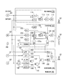
- the combined cycle plant of this embodiment includes a gas turbine 10, an exhaust heat recovery boiler 20 that generates steam by the heat of combustion gas exhausted from the gas turbine 10, and an exhaust heat recovery boiler 20.
- the generator 40 that generates electric power by driving the turbines 10, 30, the condenser 23 that returns the steam exhausted from the steam turbine 30 to water, and the condenser 23
- a water supply pump 25 that sends water to the exhaust heat recovery boiler 20 and a control device 100 that controls them are provided.
- the gas turbine 10 includes a compressor 11 that compresses the outside air A to generate compressed air, a combustor 15 that mixes the fuel F with the compressed air and burns it to generate high-temperature combustion gas, and a turbine driven by the combustion gas. 16.
- the compressor 11 includes a compressor rotor 12 that rotates about an axis, a compressor casing 13 that rotatably covers the compressor rotor 12, and an intake air amount that adjusts the flow rate of air sucked into the compressor casing 13. And a regulator 14.
- the intake air amount adjuster 14 includes an IGV (inlet guide vane) 14a provided in the suction port of the compressor casing 13, and a driver 14b that drives the IGV 14a to adjust the opening degree of the IGV 14a.
- the turbine 16 includes a turbine rotor 17 that rotates about the axis by the combustion gas from the combustor 15 and a turbine casing 18 that covers the turbine rotor 17 rotatably.
- the turbine rotor 17 and the compressor rotor 12 rotate about the same axis, and are connected to each other to form a gas turbine rotor 19.
- the exhaust port of the turbine 16 is connected to the exhaust heat recovery boiler 20. Therefore, the exhaust gas EG that is the combustion gas exhausted from the turbine 16 is guided to the exhaust heat recovery boiler 20.
- the steam turbine 30 includes a steam turbine rotor 31 that rotates about an axis, and a steam turbine casing 32 that rotatably covers the steam turbine rotor 31.
- the steam contact portion for example, the first stage stationary blade ring on the steam inlet side in the steam turbine casing 32 is used.
- a warm mode in which the temperature T2 is lower than a predetermined second temperature (eg, 400 ° C.) above the first temperature
- a hot mode with two or more temperatures.
- the startup mode that combines the warm mode and the hot mode is referred to as a normal startup mode.
- the steam turbine 30 is stopped when the steam turbine 30 is stopped, and the temperature T2 of the steam contact portion in the steam turbine casing 32 is a predetermined fourth temperature (for example, 150 ° C.). Lower cooling stop mode and a normal stop mode of the fourth temperature or higher.
- the generator 40 has a generator rotor 41 that rotates about an axis, and a generator casing 42 that rotatably covers the generator rotor 41.
- the generator casing 42 has a stator that is disposed opposite to the outer peripheral side of the generator rotor 41.
- the combined cycle plant of this embodiment is a uniaxial combined cycle plant.
- the combined cycle plant of this embodiment is a uniaxial type, this invention is not limited to this.
- a fuel line 51 that supplies fuel F from a fuel supply source to the combustor 15 is connected to the combustor 15 of the gas turbine 10.
- the fuel line 51 is provided with a fuel flow rate adjustment valve 52 that adjusts the flow rate of the fuel F flowing into the combustor 15.
- a condenser 23 is installed at the steam outlet of the steam turbine 30.
- the condenser 23 and the water supply port of the exhaust heat recovery boiler 20 are connected by a water supply line 24.
- the water supply line 24 is provided with the above-described water supply pump 25.
- the steam outlet of the exhaust heat recovery boiler 20 and the steam inlet of the steam turbine 30 are connected by a steam line 21.
- the steam line 21 is provided with a steam flow rate adjusting valve 22 that adjusts the flow rate of the steam S flowing into the steam turbine 30.
- a steam thermometer 61 that detects the temperature T ⁇ b> 1 of the steam S passing through the steam line 21 is provided on the upstream side of the steam flow control valve 22 (exhaust heat recovery boiler 20 side). Further, on the steam inlet side of the steam turbine casing 32, a metal thermometer 62 for detecting the temperature T2 of the steam contact portion (for example, the first stage stationary blade ring) of the steam turbine casing 32 is provided.
- the power generator 40 is provided with an output meter 63 that detects the amount of power generated by the power generator 40, in other words, the output PW of the combined cycle plant. Any one of the generator rotor 41, the steam turbine rotor 31, and the gas turbine rotor 19 is provided with a rotational speed meter 64 that detects the rotational speed N of the rotor.
- the control device 100 includes a fuel controller 110 that controls the opening of the fuel flow control valve 52, an IGV controller 120 that controls the opening of the intake air adjuster 14, and a steam flow control valve.
- a steam controller 140 that controls the opening degree of 22, and a stop mode receiver 160 that receives whether or not the mode for stopping the steam turbine 30 is set to the cooling stop mode.
- the fuel controller 110 includes a first fuel flow rate generator 111 that generates a fuel flow rate corresponding to the rotational speed N detected by the rotational speed meter 64, a load command from the outside, and an output PW detected by the output meter 63.
- a second fuel flow rate generator 112 for generating a corresponding fuel flow rate, and selectively outputting one of the fuel flow rate generated by the first fuel flow rate generator 111 and the fuel flow rate generated by the second fuel flow rate generator 112.
- the limiter 114 that limits the fuel flow rate change rate that is the amount of change per unit time of the fuel flow rate from the fuel flow rate switch 113, and the fuel flow rate output from the limiter 114 And a command output unit 115 that outputs a command indicating the opening degree of the fuel flow control valve 52.
- the first fuel flow rate generator 111 has a function Fx1 that defines the relationship between the planned number of revolutions at each time and the fuel flow rate so that the number of revolutions N of the gas turbine rotor 19 increases, for example, in a predetermined pattern. ing.
- the first fuel flow generator 111 uses this function Fx1 to determine the fuel flow rate at which the current scheduled rotational speed can be obtained. Further, if there is a deviation between the rotational speed N detected by the rotational speed meter 64 and the current rotational speed, the first fuel flow generator 111 corrects the previously determined fuel flow rate. The fuel flow rate is generated.
- the second fuel flow rate generator 112 has a function Fx2 that defines the relationship between the output indicated by the load command from the outside and the output PW detected by the output meter 63 and the fuel flow rate.
- the second fuel flow rate generator 112 uses this function Fx2 to generate a fuel flow rate corresponding to an external load command, an output PW detected by the output meter 63, and the like.
- the fuel flow rate switch 113 outputs the fuel flow rate from the first fuel flow rate generator 111 from the start of startup of the gas turbine 10 until it receives an insertion command from the outside.
- the fuel flow rate switch 113 outputs the fuel flow rate from the second fuel flow rate generator 112 when it receives an insertion command from the outside.
- the limiter 114 limits the fuel flow rate change rate of the fuel flow output from the fuel flow rate switch 113 to a predetermined value or less.
- the command output unit 115 creates a command indicating the opening degree of the fuel flow rate adjustment valve 52 corresponding to the fuel flow rate output from the limiter 114, and outputs this command to the fuel flow rate adjustment valve 52.
- the IGV controller 120 includes a first opening degree generator 121 that generates a target first opening degree G1 of the intake air amount regulator 14 and a second opening degree that generates a target second opening degree G2 of the intake air amount regulator 14.
- the first switch 124 that selectively outputs one of the openings G2 and the opening that is output by the first switch 124 and the opening Gn when the gas turbine is started are selected.
- the IGV controller 120 further includes a mode recognition unit 127 that recognizes the mode of the steam turbine 30, a command output unit 128 that outputs a command indicating the opening degree output from the limiter 126 to the intake air amount regulator 14, First switching command generators 131a and 131b that output a switching command to one switching device 124, and a second switching command generator 132 that outputs a switching command to the second switching device 125.
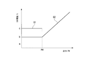
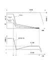
- the second opening generator 122 has a function Gx2 that defines the relationship between the output PW detected by the output meter 63 and the second opening G2 of the intake air amount adjuster 14. As shown in FIG. 3, this function Gx2 indicates a constant opening b as the second opening G2 until the output PW detected by the output meter 63 reaches a predetermined output PW1.
- the function Gx2 indicates an opening having a positive correlation with the change in the output PW as the second opening G2 when the output PW detected by the output meter 63 is equal to or greater than a predetermined output PW1. .
- the second opening generator 122 generates a second opening G2 corresponding to the output detected by the output meter 63 using the function Gx2.
- the second opening generator 122 includes a third opening generator that generates a third opening described later, a fifth opening generator that generates a fifth opening described below, and a sixth opening generator described below. It also functions as a sixth opening generator for generating the opening. However, the second opening generator 122 has a function Gx2 regardless of whether it functions as a third opening generator, a fifth opening generator, or a sixth opening generator. Is used to generate an opening corresponding to the output detected by the output meter 63.
- the first opening degree generator 121 has a function Gx1 that defines the relationship between the output PW detected by the output meter 63 and the first opening degree G1 of the intake air amount regulator 14. As shown in FIG. 3, the function Gx1 indicates the first opening G1 until the output PW detected by the output meter 63 is less than the output PW1 described above. This function Gx1 indicates a constant opening degree c as the first opening degree G1 when the output PW detected by the output meter 63 is from 0 to less than the output PW1 described above. This opening degree c is larger than the aforementioned opening degree b. The first opening degree generator 121 generates a first opening degree G1 corresponding to the output detected by the output meter 63 using this function Gx1.
- this 1st opening degree generator 121 functions also as a 4th opening degree generator which generate
- this first opening degree generator 121 functions as a fourth opening degree generator, it uses the function Gx1 to generate an opening degree.
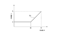
- the gas turbine startup opening generator 123 has a function Gxn that defines the relationship between the rotational speed N of the gas turbine 10 and the opening of the intake air regulator 14 at startup.
- This function Gxn indicates the opening degree of the gas turbine 10 up to the rated speed N1, as shown in FIG.
- This function Gxn indicates a constant opening a until the rotational speed N detected by the rotational speed meter 64 reaches a predetermined rotational speed N0.
- This predetermined rotation speed N0 is smaller than the rated rotation speed N1.
- the function Gxn indicates an opening having a positive correlation with a change in the rotational speed N when the rotational speed N detected by the rotational speed meter 64 becomes equal to or greater than a predetermined output NO. Is gradually increased from the degree of opening a.
- the opening degree b at which the rotational speed N detected by the rotational speed meter 64 corresponds to the rated rotational speed N1 is the aforementioned opening degree b.
- the mode recognition unit 127 recognizes whether the start mode of the steam turbine 30 is the cold mode or the normal start mode according to the temperature T2 detected by the metal thermometer 62. Specifically, when the temperature T2 of the steam contact portion of the steam turbine casing 32 detected by the metal temperature is lower than the first temperature (for example, 300 ° C.), the cold mode is recognized, and this first temperature is detected. When it is above, it recognizes that it is normal starting mode. Further, the mode recognition unit 127 recognizes whether the stop mode of the steam turbine 30 is the cooling stop mode or the normal stop mode according to the input operation of the stop mode receiver 160.
- the first temperature for example, 300 ° C.
- the first switching command generators 131a and 131b include a first a switching command generator 131a that generates a switching command “1” for opening control in the cold mode and opening control in the cooling stop mode, and an opening in the cold mode.
- the mode recognition unit 127 recognizes that the activation mode is the cold mode, the first a switching command generator 131a generates a switching command “1” for opening degree control in the cold mode.
- the first a switching command generator 131a recognizes that the stop mode is the cooling stop mode by the mode recognition unit 127 and the output PW detected by the output meter 63 is equal to or lower than the predetermined output PW1
- a switching command “1” for opening degree control in the cooling stop mode is generated.
- the first b switching command generator 131b switches the opening degree control end in the cold mode when the mode recognition unit 127 recognizes that the start mode is the cold mode and the steam flow rate control valve 22 is opened from the closed state. Command “0” is generated.
- the first switch command generator 131a When the first switch command generator 131a generates a switching command “1” for opening control in the cold mode and opening control in the cooling stop mode, the first switch 124 and the second opening command generator 131a The first opening G1 is output from the degree G2. Further, the first switch 124, when the first b switching command generator 131b generates a switching command “0” for ending the opening control in the cold mode, of the first opening G1 and the second opening G2. Two opening G2 is output.
- the second switching command generator 132 generates a switching command “1” for opening degree control at the time of starting the gas turbine when the rotational speed N detected by the rotational speed meter 64 is less than the rated rotational speed N1.
- the second switching unit 125 opens from the opening degree generator 123 at the time of starting the gas turbine.
- the degree Gn and the opening degree from the first switch 124 the gas turbine starting opening degree Gn from the gas turbine starting opening degree generator 123 is output.
- the second switching command generator 132 generates a switching command “0” for opening degree control at the time of starting the gas turbine when the rotational speed N detected by the rotational speed meter 64 becomes equal to or higher than the rated rotational speed N1.
- the second switching command generator 132 generates a switching command “0” for ending the opening degree control when the gas turbine is started, the second switching unit 125 is opened when the gas turbine starts from the opening degree generator 123 when the gas turbine starts.
- the degree Gn and the opening degree from the first switch 124 and the opening degree from the first switch 124 are output.
- the limiter 126 limits the change rate of the opening degree output from the second switch 125 to a predetermined change rate or less. This predetermined change rate is changed according to the state of the combined cycle plant.
- the command output unit 128 outputs a command indicating the opening degree at which the rate of change is limited by the limiter 126 to the intake air amount adjuster 14 as described above.
- the steam controller 140 includes an open condition determining unit 141 that determines whether or not the opening condition of the steam flow rate control valve 22 is satisfied, and a closing condition determining unit that determines whether or not the closing condition of the steam flow rate control valve 22 is satisfied. 151, an opening-time opening generator 155 that generates an opening in the process of opening the steam flow control valve 22, and a closed-time opening generator 156 that generates an opening in the process of closing the steam flow control valve 22. And a command output unit 157 for outputting a command corresponding to the opening generated by the opening-time opening generator 155 or the opening generated by the closing-time opening generator 156 to the steam flow rate control valve 22.
- the open condition determination unit 141 includes a subtractor 142, a first determiner 143, a second determiner 144, a third determiner 145, a fourth determiner 146, an OR circuit 147, and a first AND circuit 148. And a second AND circuit 149.
- T1-T2 the temperature T1 of the steam S is equal to or higher than (the current steam pressure saturation temperature + specific superheat degree) Te.
- the first determiner 143 has a lower limit value for opening the steam flow rate control valve 22. “1” is output as it is established.
- the second determiner 144 assumes that the upper limit value for opening the steam flow rate control valve 22 is established for the temperature S1 of the steam S. Is output. If the temperature deviation ⁇ T is equal to or less than a predetermined temperature deviation ⁇ Tmax, the third determiner 145 outputs “1”, assuming that the upper limit value for opening the steam flow rate control valve 22 is established. . When the temperature deviation ⁇ T is equal to or greater than a predetermined temperature deviation ⁇ Tmin ( ⁇ Tmin is a negative value), the fourth determiner 146 has a lower limit value for opening the steam flow rate control valve 22. “1” is output.
- the OR circuit 147 outputs “1” when the second determiner 144 or the third determiner 145 outputs “1”.
- the first AND circuit 148 outputs “1” when the fourth determiner 146 outputs “1” and the OR circuit 147 outputs “1”.
- the second AND circuit 149 outputs “1” when the first determiner 143 outputs “1” and the first AND circuit 148 outputs “1”.
- the second AND circuit 149 of the open condition determination unit 141 outputs “1”, assuming that the open condition of the steam flow rate control valve 22 is satisfied when the following temperature conditions (1) and (2) are satisfied. .
- Upper limit value of temperature The temperature T1 of the steam S is not more than a predetermined upper limit temperature Tmax, or the temperature deviation ⁇ T is not more than a predetermined temperature deviation ⁇ Tmax.
- Lower temperature limit The temperature T1 of the steam S is equal to or higher than (the current steam pressure saturation temperature + specific superheat degree) Te, or the temperature deviation ⁇ T is a predetermined temperature deviation ⁇ Tmin ( ⁇ Tmin is a negative value) ) That's it.
- the temperature T1 of the steam S in the steam line 21 and the steam contact portion of the steam turbine casing 32 are used as the condition for opening the steam flow rate adjusting valve 22, that is, the condition for starting steam supply to the steam turbine 30.
- the upper and lower limit values of the temperature deviation ⁇ T with respect to the temperature T2 are determined. This is to suppress the generation of thermal stress in the steam turbine 30 when the supply of steam to the steam turbine 30 is started.
- the opening-time opening generator 155 When the opening condition determination unit 141 outputs “1”, the opening-time opening generator 155 generates an opening that increases at a predetermined rate of change. This rate of change may be changed according to various conditions.
- the closing condition determination unit 151 includes a fifth determination unit 152.
- the fifth determiner 152 determines the steam flow rate control valve 22. Is output as “1”.
- the closing-time opening generator 156 When the closing condition determination unit 151 outputs “1”, the closing-time opening generator 156 generates an opening that decreases at a predetermined rate of change. This rate of change may be changed according to various conditions. For example, the change rate may be increased when the stop mode is the normal stop mode, and may be decreased when the stop mode is the cooling stop mode.
- the command output unit 157 outputs a command corresponding to the opening generated by the opening-time opening generator 155 or the opening generated by the closing-time opening generator 156 to the steam flow rate control valve 22.
- control device 100 of the present embodiment is configured by a computer, and all the processes of each part of the control device 100 are performed by an external storage device such as a hard disk drive device, a storage device such as a memory, and the storage device. And a CPU that executes a stored program.
- an external storage device such as a hard disk drive device, a storage device such as a memory, and the storage device.
- a CPU that executes a stored program.
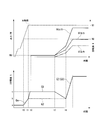
- the control device 100 When the control device 100 receives a load command indicating the start of the combined cycle plant from the outside, the control device 100 outputs a start command to a starter (not shown) and starts the starter. By starting the starter, the compressor rotor 12 and the turbine rotor 17 of the gas turbine 10 start to rotate integrally. When the compressor rotor 12 rotates, the compressed air from the compressor 11 starts to be supplied to the combustor 15. For example, when the compressor rotor 12 and the turbine rotor 17, that is, the gas turbine rotor 19 reach a predetermined rotation speed N 0 (t 0), the fuel controller 110 of the control device 100 issues an open command to the fuel flow rate adjustment valve 52. Output.
- the fuel F from the fuel line 51 starts to be supplied to the combustor 15 through the fuel flow rate adjustment valve 52.
- the fuel F burns in the compressed air supplied from the compressor 11 to the combustor 15.
- the combustion gas generated in the combustor 15 flows into the turbine 16 and rotates the gas turbine rotor 19.
- the fuel flow rate from the first fuel flow rate generator 111 of the fuel controller 110 is sent to the limiter 114 via the fuel flow rate switch 113.
- the first fuel flow rate generator 111 uses the function Fx1 to determine the fuel flow rate at which the current rotational speed can be obtained. Further, if there is a deviation between the rotational speed N detected by the rotational speed meter 64 and the current rotational speed, the first fuel flow generator 111 corrects the previously determined fuel flow rate.
- the fuel flow rate is generated.
- the limiter 114 limits the rate of change of the fuel flow rate from the first fuel flow rate generator 111 so that the rate of change of the fuel flow rate is equal to or lower than a predetermined rate of change, and outputs this.
- the command output unit 115 outputs a command indicating an opening degree corresponding to the fuel flow rate output from the limiter 114 to the fuel flow rate adjustment valve 52.
- the rotational speed N of the gas turbine rotor 19 basically increases in a predetermined pattern.
- the second switching command generator 132 of the IGV controller 120 generates a switching command “1” when the rotational speed N detected by the rotational speed meter 64 is less than the rated rotational speed N1.
- the second switch 125 of the IGV controller 120 receives the switching command “1”, and among the opening from the opening generator 123 at the time of starting the gas turbine and the opening from the first switch 124, the gas turbine The opening degree from the starting opening degree generator 123 is sent to the limiter 126. Therefore, when the fuel supply to the combustor 15 is started, that is, when the rotational speed N detected by the rotational speed meter 64 is less than the rated rotational speed N1, the opening of the IGV controller 120 from the opening degree generator 123 at the time of starting the gas turbine.
- the degree is sent to the limiter 126 via the second switch 125.
- the opening degree generator 123 at the time of starting the gas turbine uses the function Gxn to generate an opening degree corresponding to the rotational speed N detected by the rotational speed meter 64 as the opening degree Gn at the time of starting the gas turbine. As described above with reference to FIG. 4, the opening generated by the gas turbine start-up opening generator 123 is determined until the rotational speed N detected by the rotational speed meter 64 reaches a predetermined rotational speed N0 (t0). ), A constant opening a.
- the opening generated by the opening generator 123 at the time of starting the gas turbine is such that when the rotational speed N detected by the rotational speed meter 64 becomes equal to or higher than a predetermined output N0 (t0), the rotational speed N is changed. Change with positive correlation. That is, the opening generated by the opening generator 123 at the time of starting the gas turbine increases as the rotational speed N increases.
- the limiter 126 limits the rate of change of the opening from the opening generator 123 at the time of starting the gas turbine so that the rate of change of the opening of the intake air regulator 14 is not more than a predetermined rate of change.
- the command output unit 128 outputs a command indicating the opening degree output from the limiter 126 to the intake air amount adjuster 14.
- the opening degree of the intake air amount adjuster 14 becomes the opening degree b just before the rotational speed N of the gas turbine rotor 19 reaches the rated rotational speed N1.
- the mode recognition unit 127 of the IGV controller 120 recognizes whether the start mode of the steam turbine 30 is the cold mode or the normal start mode according to the temperature T2 of the steam turbine casing 32 detected by the metal thermometer 62. (Start mode recognition step).
- the mode recognition unit 127 recognizes that the startup mode is the normal startup mode
- the first a switching command generator 131a generates a switching command “0” for opening degree control in the normal startup mode.
- the first switch 124 receives the switching command “0” from the first a switching command generator 131 a
- the first switching device 124 receives the first opening G 1 from the first opening generator 121 and the second opening generator 122. Of the two opening degrees G2, the second opening degree G2 from the second opening degree generator 122 is output.
- the second opening degree G2 is detected by the output meter 63 at a constant opening degree b until the output PW detected by the output meter 63 reaches a predetermined output PW1.
- the opening has a positive correlation with the change in the output PW.
- the rotational speed N of the gas turbine rotor 19 becomes the rated rotational speed N1 before the output PW detected by the output meter 63 becomes equal to or higher than the predetermined output PW1 (t1).
- the second switching command generator 132 generates a switching command “0” when the rotational speed N detected by the rotational speed meter 64 becomes equal to or higher than the rated rotational speed N1 (t1).
- the second switching device 125 receives this switching command “0”, the first switching device 124 out of the opening from the gas turbine start-up opening generator 123 and the opening from the first switching device 124. , That is, the first opening G1 generated by the first opening generator 121 or the second opening G2 generated by the second opening generator 122 is sent to the limiter 126.
- the second switch 125 sends the second opening G2 generated by the second opening generator 122 to the limiter 126.
- the limiter 126 limits the change rate of the opening degree from the second opening degree generator 122 so that the change rate of the opening degree of the intake air amount regulator 14 is not more than a predetermined change rate, and outputs this.
- the command output unit 128 outputs a command indicating the opening degree output from the limiter 126 to the intake air amount adjuster 14 (command output step).
- the first a switching command generator 131a When the mode recognition unit 127 recognizes that the activation mode is the cold mode, the first a switching command generator 131a generates a switching command “1” for opening control in the cold mode.
- the first switching device 124 receives the switching command “1” from the first a switching command generator 131 a, the first switching device 124 receives the first opening G 1 from the first opening generator 121 and the second opening generator 122. Of the two opening degrees G2, the first opening degree G1 from the first opening degree generator 121 is output.
- the first opening degree G1 is a constant opening degree c that is larger than the opening degree b in the normal startup mode.
- the second switching command generator 132 generates the switching command “0” when the rotational speed N detected by the rotational speed meter 64 becomes equal to or higher than the rated rotational speed N1 (t1).
- the second switching device 125 receives this switching command “0”, the first switching device 124 out of the opening from the gas turbine start-up opening generator 123 and the opening from the first switching device 124.
- the first opening G1 generated by the first opening generator 121 or the second opening G2 generated by the second opening generator 122 is sent to the limiter 126.
- the second switch 125 sends the opening degree c, which is the first opening degree G1 generated by the first opening degree generator 121, to the limiter 126.
- the opening just before the second switch 125 is switched is the opening b which is the opening Gn at the time of starting the gas turbine when the gas turbine rotor 19 is at the rated rotational speed N1.
- the opening degree immediately after the second switch 125 is switched is the opening degree c which is the first opening degree G1 larger than the opening degree b.
- the limiter 126 limits the change rate of the opening degree from the second opening degree generator 122 so that the change rate of the opening degree of the intake air amount adjuster 14 is not more than a predetermined change rate. That is, the limiter 126 limits the rate of change of the opening from the second opening generator 122 so as to gradually increase from the opening b before switching of the second switch 125 to the opening c.
- the command output unit 128 outputs a command indicating the opening degree output from the limiter 126 to the intake air amount adjuster 14 (command output step).
- the control apparatus 100 When the rotational speed N of the gas turbine rotor 19 reaches the rated rotational speed N1 and a predetermined condition is satisfied, the control apparatus 100 is externally instructed to electrically connect the generator 40 and external system power. A command is input (t2). When this insertion command is input (t2), the circuit breaker is closed and the generator 40 and the external system power are electrically connected. As a result, the output PW from the output meter 63 can be obtained from this time (t2). When the generator 40 is connected to the system power line, the rotational speed of the gas turbine rotor 19 is maintained at the rated rotational speed N1 thereafter.
- the fuel flow switch 113 of the fuel controller 110 accepts the insertion command, the fuel flow switch 113 of the fuel flow from the first fuel flow generator 111 and the fuel flow from the second fuel flow generator 112
- the fuel flow rate from the dual fuel flow rate generator 112 is output.
- the second fuel flow rate generator 112 generates a fuel flow rate corresponding to the load command from the outside, the output PW detected by the output meter 63, and the like using the function Fx2.
- the fuel amount flow rate from the second fuel flow rate generator 112 is sent to the limiter 114 via the fuel flow rate switch 113.
- the limiter 114 limits the fuel flow rate change rate of the fuel flow output from the fuel flow rate switch 113 to a predetermined value or less.
- the command output unit 115 creates a command indicating the opening degree corresponding to the fuel flow rate output from the limiter 114, and outputs this command to the fuel flow rate adjustment valve 52.
- the load command from the outside is basically constant until the condition for starting the supply of steam to the steam turbine 30 is satisfied.
- the opening degree of the fuel flow control valve 52 is constant until the condition for starting the supply of steam to the steam turbine 30 is satisfied after the insertion, and the output PW during this period is also constant PW1.
- the load command from the outside when the condition for starting the supply of steam to the steam turbine 30 is satisfied (t3), the load value indicated by the load command gradually increases. For this reason, when the condition for starting the supply of steam to the steam turbine 30 is satisfied (t3), the opening of the fuel flow control valve 52 gradually increases and the output PW also gradually increases. Thereafter, until the gas turbine 10 is stopped, the fuel flow rate adjustment valve 52 is controlled to an opening degree corresponding to the fuel amount flow rate from the second fuel flow rate generator 112.
- the first b switching command generator 131b of the IGV controller 120 is recognized by the mode recognition unit 127 that the activation mode is the cold mode, and the open condition determination unit 141 of the steam controller 140 satisfies the steam supply start condition.
- a switching command “0” for terminating the opening degree control in the cold mode is generated.
- the first switch 124 receives the switching command “0” from the first b switching command generator 131 b
- the first switching device 124 receives the first opening G 1 from the first opening generator 121 and the second opening generator 122. Of the two opening degrees G2, the second opening degree G2 from the second opening degree generator 122 is output. At this time, the first switch 124 functions as a third switch.
- the second opening degree G2 is sent to the limiter 126 via the second switch 125.
- the opening just before the first switch (third switch) 124 is switched is the opening c which is the first opening G1.
- the opening degree immediately after the first switcher (third switcher) 124 is switched is the opening degree b that is the second opening degree G2 generated by the second opening degree generator 122.
- the limiter 126 limits the change rate of the opening degree from the second opening degree generator 122 so that the change rate of the opening degree of the intake air amount adjuster 14 is not more than a predetermined change rate. That is, the limiter 126 limits the rate of change of the opening from the second opening generator 122 so that the opening c before the switching of the second switch 125 gradually decreases to the opening b.
- the change rate of the opening degree at this time is the change in the opening degree when the rotation speed N detected by the revolution meter 64 becomes equal to or higher than the rated rotation speed N1 (t1) and the opening degree b is switched to the opening degree c. It may be different from the rate.
- the limiter 126 receives the switching command “0” from the first b switching command generator 131b and changes the change rate of the opening degree.
- the opening degree of the intake air amount regulator 14 is controlled to the second opening degree G2 generated by the second opening degree generator 122 until the control for stopping the steam turbine 30 together with the gas turbine 10 is started.
- the second opening generator 122 functions as the third opening generator described above.
- the second opening degree generator 122 functions as a third opening degree generator
- the second opening degree G2 is output as the third opening degree G3.
- the temperature T1 of the steam S in the steam line 21 and the steam contact portion of the steam turbine casing 32 are used as the condition for opening the steam flow rate adjusting valve 22, that is, the condition for starting steam supply to the steam turbine 30.
- the upper and lower limit values of the temperature deviation ⁇ T with respect to the temperature T2 are determined.
- a predetermined temperature for example, 300 ° C.
- the temperature T1 of the steam S in the steam line 21 and the steam of the steam turbine casing 32 are reduced.
- a temperature deviation ⁇ T from the temperature T2 of the contact portion increases. Therefore, there is a high possibility that this temperature deviation ⁇ T does not fall within the range of the upper and lower limit values, which is one of the steam supply start conditions.
- the opening amount of the intake air amount regulator 14 is made larger than that in the normal start mode.
- the flow control of the fuel supplied to the combustor 15 of the gas turbine 10 is the same in the cold mode and the normal startup mode.
- the air flow rate with respect to the fuel flow rate supplied to the gas turbine 10 is greater in the cold mode than in the normal startup mode. Therefore, in the present embodiment, the temperature of the combustion gas is lower and the temperature of the steam is lower in the cold mode than in the normal startup mode.
- the temperature of the steam contact portion of the steam turbine casing 32 in the cold mode is lower than the predetermined temperature in this way, the temperature of the steam is lower than that in the normal startup mode.
- the temperature deviation ⁇ T between the temperature T1 of S and the temperature T2 of the steam contact portion can be suppressed.
- the steam supply start condition can be easily satisfied even in the cold mode.
- the opening degree control in the cold mode is performed by properly using the first opening degree G1 from the first opening degree generator 121 and the second opening degree G2 from the second opening degree generator 122. And opening degree control in the normal start mode.
- the opening degree control of the intake air amount regulator 14 before the start of the supply of steam to the steam turbine 30 can be performed by a simple method.
- the configuration of the IGV controller 120 that executes the opening degree control of the intake air amount regulator 14 before the start of supply of steam to the steam turbine 30 can be simplified.
- the control system when switching from one opening to another opening among the opening generated from each opening generator, there is a deviation between one opening and another opening. Therefore, since the opening is gradually changed from one opening to another, the confusion of the control system at the time of opening switching can be suppressed. Therefore, in the present embodiment, as described above, even if the first opening G1 from the first opening generator 121 and the second opening G2 from the second opening generator 122 are selectively used, the control system Can reduce confusion.
- the fuel flow rate adjustment valve 52 is controlled to an opening degree corresponding to the fuel flow rate generated from the second fuel generator of the fuel controller 110. Further, the intake air flow controller is controlled to an opening corresponding to the second opening G ⁇ b> 2 generated from the second opening generator 122 of the IGV controller 120. At this time, the second opening generator 122 functions as the aforementioned third opening generator and sixth opening generator. When the second opening generator 122 functions as a third opening generator, the second opening G2 outputs the second opening G2 as the third opening G3, and functions as a sixth opening generator. In this case, the second opening G2 is output as the sixth opening G6. Further, the steam flow rate control valve 22 is basically maintained in a fully opened state.
- the operator Before stopping the combined cycle plant, the operator operates the stop mode acceptor 160 of the control device 100 to set the stop mode of the steam turbine 30 to the cooling stop mode or to the normal stop mode for the control device 100. Enter what you want to do.
- the mode recognition unit 127 recognizes whether the stop mode of the steam turbine 30 is the cooling stop mode or the normal stop mode according to the operation result of the stop mode acceptor 160 (stop mode recognition step).
- the second fuel flow rate generator 112 of the fuel controller 110 When the control device 100 receives a load command indicating the stop of the combined cycle plant from the outside (t6), the second fuel flow rate generator 112 of the fuel controller 110 outputs a fuel flow rate corresponding to the load included in the load command. To come. That is, the second fuel flow rate generator 112 outputs a fuel flow rate that gradually decreases. For this reason, while the output of the gas turbine 10 falls gradually, the output of the steam turbine 30 also falls gradually.
- the fifth determination unit 152 of the closing condition determination unit 151 in the steam controller 140 is configured to output a predetermined output PW detected by the output meter 63 after a load command indicating the stop of the combined cycle plant is input from the outside.
- PW1 or less (t7) “1” is output, assuming that the condition for closing the steam flow rate control valve 22 is satisfied.
- the closing condition determination unit 151 outputs “1”
- the closing-time opening generator 156 generates an opening that decreases at a predetermined rate of change.
- the command output unit 157 outputs a command corresponding to the opening degree generated by the closing-time opening degree generator 156 to the steam flow rate adjustment valve 22. For this reason, the opening degree of the steam flow rate control valve 22 is gradually reduced thereafter.
- the first switch 124 When the first switch 124 receives this switching command “0”, the first switch 124 outputs the second opening G2 of the first opening G1 and the second opening G2 (command output step). ). The first switch 124 outputs the second opening G2 of the first opening G1 and the second opening G2 when the gas turbine 10 and the steam turbine 30 are in steady operation. Thus, even if the first switch 124 receives the switching command “0”, the opening degree to be output is not changed before and after the switching command “0” is received, and the second opening G2 remains unchanged. In addition, immediately after the first switch 124 is switched, the second opening generator 122 functions as the fifth opening generator described above. When the second opening degree generator 122 functions as a fifth opening degree generator, the second opening degree G2 is output as the fifth opening degree G5.
- the command corresponding to the second opening G2 generated by the second opening generator 122 is issued even after the closing condition of the steam flow rate control valve 22 is satisfied. It is sent to the regulator 14.
- the function Gx2 of the second opening degree generator 122 basically has a positive correlation with the change in the output PW as the second opening degree G2, as described above with reference to FIG. Indicates the opening degree. However, this function Gx2 indicates a constant opening degree b when the output PW detected by the output meter 63 is equal to or less than a predetermined output PW1.
- the opening degree G2 is a constant opening degree b. This constant opening degree b is sent to the command output device 128 via the limiter 126.
- the command output unit 128 outputs a command indicating the constant opening degree b to the intake air amount adjuster 14.
- the mode recognition unit 127 recognizes that it is in the cooling stop mode, the output PW detected by the output meter 63 becomes equal to or less than the predetermined output PW1, and the closing condition determination unit 151 in the steam controller 140 is detected.
- the first a switching command generator 131a generates a switching command “1” for opening degree control in the cooling stop mode. To do.
- the first switch 124 receives the switching command “1”
- the first switch 124 outputs a constant opening c that is the first opening G1 out of the first opening G1 and the second opening G2.
- the first opening degree G1 is sent to the limiter 126 via the second switch 125.
- the opening just before the first switch 124 is switched is the opening b.
- the opening immediately after the first switch 124 is switched is a constant opening c that is the first opening G1 generated by the first opening generator 121.
- the limiter 126 limits the change rate of the opening degree from the first opening degree generator 121 so that the change rate of the opening degree of the intake air amount regulator 14 is not more than a predetermined change rate. That is, the limiter 126 limits the change rate of the opening from the first opening generator 121 so that the opening b before the switching of the second switch 125 gradually increases from the opening c.
- the change rate of the opening degree at this time is the change in the opening degree when the rotation speed N detected by the revolution meter 64 becomes equal to or higher than the rated rotation speed N1 (t1) and the opening degree b is switched to the opening degree c. It may be different from the rate.
- the limiter 126 receives the switching command “1” from the first a switching command generator 131a and changes the change rate of the opening degree.
- the limiter 126 continues to output the opening degree c.
- the command output unit 128 outputs a command indicating the opening degree output from the limiter 126 to the intake air amount adjuster 14 (command output step).
- the 1st opening degree generator 121 functions as the above-mentioned 4th opening degree generator.
- the first opening G1 is output as the fourth opening G4.
- the opening degree of the intake air amount regulator 14 is made larger than that in the normal stop mode.
- the flow control of the fuel supplied to the combustor 15 of the gas turbine 10 is the same in the cooling stop mode and in the normal stop mode.
- the air flow rate with respect to the fuel flow rate supplied to the gas turbine 10 is greater in the cooling stop mode than in the normal stop mode. Therefore, in this embodiment, the temperature of the combustion gas is lower and the temperature of the steam is lower in the cooling stop mode than in the normal stop mode.
- the cooling stop mode is selected as the stop mode of the steam turbine 30 as described above, the temperature of the steam is lower than that in the normal stop mode. can do.
- the first opening G1 from the first opening generator 121 and the second opening G2 from the second opening generator 122 are selectively used, so that the opening in the cooling stop mode is used.
- the control and the opening degree control in the normal stop mode are executed.
- the opening degree control of the intake air amount adjuster 14 in the process of stopping the steam turbine 30 can be performed by a simple method.
- the configuration of the IGV controller 120 that executes the opening degree control of the intake air amount adjuster 14 in the process of stopping the steam turbine 30 can be simplified.
- the opening degree generated from each opening degree generator is changed from one opening degree.
- the opening is gradually changed from one opening to the other opening. Control system confusion can be suppressed.
- the first opening G1 and the second opening from the first opening generator 121 are the same as in the opening control of the intake air amount regulator 14 before the start of steam supply to the steam turbine 30. Even if the second opening G2 from the generator 122 is properly used, the confusion of the control system can be suppressed.
- the first opening generator 121 has an original function Gx1, and the first opening G1 is generated using this function Gx1.
- the first opening generator may add a predetermined value to the second opening G2 generated by the second opening generator.
- the first opening G1 employed when the start mode is the cold mode and the first opening G1 employed when the stop mode is the cooling stop mode are the same. is there.
- the first opening degree G1 adopted when the start mode is the cold mode and the opening degree adopted when the stop mode is the cooling stop mode may not be the same.
- the temperature difference between the temperature of the steam contact portion of the steam turbine and the temperature of the inflowing steam at startup can be suppressed by simple control.
- the temperature of the steam contact part can be made low in a short time.
Landscapes
- Engineering & Computer Science (AREA)
- Chemical & Material Sciences (AREA)
- Combustion & Propulsion (AREA)
- Mechanical Engineering (AREA)
- General Engineering & Computer Science (AREA)
- Physics & Mathematics (AREA)
- Geometry (AREA)
- Fluid Mechanics (AREA)
- Engine Equipment That Uses Special Cycles (AREA)
- Control Of Turbines (AREA)
Abstract
Priority Applications (4)
| Application Number | Priority Date | Filing Date | Title |
|---|---|---|---|
| DE112015001579.5T DE112015001579B4 (de) | 2014-03-31 | 2015-02-20 | Kombikraftwerk, Steuerverfahren desselben, und Steuervorrichtung desselben |
| US15/118,320 US10526923B2 (en) | 2014-03-31 | 2015-02-20 | Combined cycle plant, control method of same, and control device of same |
| CN201580008186.8A CN106030052B (zh) | 2014-03-31 | 2015-02-20 | 复合循环设备、其控制方法、以及其控制装置 |
| KR1020167023107A KR101813430B1 (ko) | 2014-03-31 | 2015-02-20 | 복합 발전 플랜트, 그 제어 방법, 및 그 제어 장치 |
Applications Claiming Priority (2)
| Application Number | Priority Date | Filing Date | Title |
|---|---|---|---|
| JP2014071408A JP6375585B2 (ja) | 2014-03-31 | 2014-03-31 | コンバインドサイクルプラント、その制御方法、及びその制御装置 |
| JP2014-071408 | 2014-03-31 |
Publications (1)
| Publication Number | Publication Date |
|---|---|
| WO2015151641A1 true WO2015151641A1 (fr) | 2015-10-08 |
Family
ID=54239977
Family Applications (1)
| Application Number | Title | Priority Date | Filing Date |
|---|---|---|---|
| PCT/JP2015/054798 WO2015151641A1 (fr) | 2014-03-31 | 2015-02-20 | Ensemble fonctionnel à cycle combiné, procédé de commande correspondant et dispositif de commande correspondant |
Country Status (6)
| Country | Link |
|---|---|
| US (1) | US10526923B2 (fr) |
| JP (1) | JP6375585B2 (fr) |
| KR (1) | KR101813430B1 (fr) |
| CN (1) | CN106030052B (fr) |
| DE (1) | DE112015001579B4 (fr) |
| WO (1) | WO2015151641A1 (fr) |
Families Citing this family (9)
| Publication number | Priority date | Publication date | Assignee | Title |
|---|---|---|---|---|
| JP6680555B2 (ja) * | 2016-02-10 | 2020-04-15 | 三菱日立パワーシステムズ株式会社 | ガスタービン制御装置、ガスタービン制御方法及びプログラム |
| EP3318732A1 (fr) * | 2016-11-07 | 2018-05-09 | Siemens Aktiengesellschaft | Procédé de fonctionnement d'une centrale à cycle combiné à gazéification intégrée |
| JP6845675B2 (ja) * | 2016-12-08 | 2021-03-24 | 川崎重工業株式会社 | 原料ガス液化装置及びその制御方法 |
| KR102103324B1 (ko) * | 2017-07-21 | 2020-04-22 | 가부시끼가이샤 도시바 | 플랜트 제어 장치, 플랜트 제어 방법, 및 발전 플랜트 |
| JP7003000B2 (ja) * | 2017-07-21 | 2022-01-20 | 株式会社東芝 | プラント制御装置、プラント制御方法、および発電プラント |
| JP7137398B2 (ja) * | 2018-08-08 | 2022-09-14 | 川崎重工業株式会社 | コンバインドサイクル発電プラント |
| JP7247071B2 (ja) * | 2019-10-01 | 2023-03-28 | 東芝エネルギーシステムズ株式会社 | プラント制御装置、プラント制御方法、および発電プラント |
| DE102019216179A1 (de) * | 2019-10-21 | 2021-04-22 | Siemens Energy Global GmbH & Co. KG | Verfahren zur Regelung der Eintrittstemperatur eines Arbeitsfluides einer Dampfturbine bei schwankender Bereitstellung thermischer Energie |
| JP7388993B2 (ja) | 2020-08-06 | 2023-11-29 | 三菱重工業株式会社 | ガスタービンの起動方法 |
Citations (6)
| Publication number | Priority date | Publication date | Assignee | Title |
|---|---|---|---|---|
| JPH03290006A (ja) * | 1990-04-06 | 1991-12-19 | Toshiba Corp | 複合サイクルプラントのガスタービン制御装置 |
| JP2000045791A (ja) * | 1998-08-04 | 2000-02-15 | Toshiba Corp | ガスタービン吸気制御装置 |
| JP2007040171A (ja) * | 2005-08-03 | 2007-02-15 | Mitsubishi Heavy Ind Ltd | ガスタービンの入口案内翼制御装置 |
| JP2007211705A (ja) * | 2006-02-10 | 2007-08-23 | Mitsubishi Heavy Ind Ltd | ガス化複合発電システムにおける空気圧力制御装置 |
| JP2008128086A (ja) * | 2006-11-21 | 2008-06-05 | Mitsubishi Heavy Ind Ltd | ガスタービンの吸気加熱制御装置 |
| JP2012057585A (ja) * | 2010-09-13 | 2012-03-22 | Hitachi Ltd | コンバインドサイクル発電プラントの起動制御装置とその起動制御方法 |
Family Cites Families (13)
| Publication number | Priority date | Publication date | Assignee | Title |
|---|---|---|---|---|
| US3974645A (en) * | 1974-08-08 | 1976-08-17 | Westinghouse Electric Corporation | Control apparatus for matching the exhaust flow of a gas turbine employed in a combined cycle electric power generating plant to the requirements of a steam generator also employed therein |
| US4638630A (en) * | 1984-12-27 | 1987-01-27 | Westinghouse Electric Corp. | Cooldown control system for a combined cycle electrical power generation plant |
| JPH0713472B2 (ja) * | 1985-01-25 | 1995-02-15 | 株式会社日立製作所 | タービンの運転制御方法、および複合サイクル原動機プラント |
| JP2680033B2 (ja) * | 1988-05-11 | 1997-11-19 | 株式会社日立製作所 | コンバインドプラントの運転方法及び装置 |
| JPH02130202A (ja) | 1988-11-08 | 1990-05-18 | Mitsubishi Heavy Ind Ltd | コンバインドプラント |
| JP2845606B2 (ja) * | 1990-10-31 | 1999-01-13 | 株式会社東芝 | 発電プラント制御装置 |
| JP3672339B2 (ja) | 1994-05-16 | 2005-07-20 | 株式会社東芝 | 一軸型コンバインドサイクルプラントの起動方法及び起動装置 |
| JP3354776B2 (ja) * | 1996-01-19 | 2002-12-09 | 株式会社クボタ | 焼却炉複合プラント設備の運転方法 |
| US8210801B2 (en) * | 2009-01-29 | 2012-07-03 | General Electric Company | Systems and methods of reducing heat loss from a gas turbine during shutdown |
| EP2642092B1 (fr) * | 2012-03-19 | 2014-10-08 | Alstom Technology Ltd | Procédé pour faire fonctionner une centrale à cycle combiné et installation pour mettre en oeuvre un tel procédé |
| US9777641B2 (en) * | 2012-12-19 | 2017-10-03 | General Electric Company | System for turbomachine vane control |
| US9545604B2 (en) * | 2013-11-15 | 2017-01-17 | General Electric Company | Solids combining system for a solid feedstock |
| US9404426B2 (en) * | 2013-12-31 | 2016-08-02 | General Electric Company | Methods and systems for enhancing control of power plant generating units |
-
2014
- 2014-03-31 JP JP2014071408A patent/JP6375585B2/ja active Active
-
2015
- 2015-02-20 DE DE112015001579.5T patent/DE112015001579B4/de active Active
- 2015-02-20 KR KR1020167023107A patent/KR101813430B1/ko active IP Right Grant
- 2015-02-20 CN CN201580008186.8A patent/CN106030052B/zh active Active
- 2015-02-20 US US15/118,320 patent/US10526923B2/en active Active
- 2015-02-20 WO PCT/JP2015/054798 patent/WO2015151641A1/fr active Application Filing
Patent Citations (6)
| Publication number | Priority date | Publication date | Assignee | Title |
|---|---|---|---|---|
| JPH03290006A (ja) * | 1990-04-06 | 1991-12-19 | Toshiba Corp | 複合サイクルプラントのガスタービン制御装置 |
| JP2000045791A (ja) * | 1998-08-04 | 2000-02-15 | Toshiba Corp | ガスタービン吸気制御装置 |
| JP2007040171A (ja) * | 2005-08-03 | 2007-02-15 | Mitsubishi Heavy Ind Ltd | ガスタービンの入口案内翼制御装置 |
| JP2007211705A (ja) * | 2006-02-10 | 2007-08-23 | Mitsubishi Heavy Ind Ltd | ガス化複合発電システムにおける空気圧力制御装置 |
| JP2008128086A (ja) * | 2006-11-21 | 2008-06-05 | Mitsubishi Heavy Ind Ltd | ガスタービンの吸気加熱制御装置 |
| JP2012057585A (ja) * | 2010-09-13 | 2012-03-22 | Hitachi Ltd | コンバインドサイクル発電プラントの起動制御装置とその起動制御方法 |
Also Published As
| Publication number | Publication date |
|---|---|
| DE112015001579B4 (de) | 2022-12-22 |
| JP2015194086A (ja) | 2015-11-05 |
| US10526923B2 (en) | 2020-01-07 |
| JP6375585B2 (ja) | 2018-08-22 |
| DE112015001579T5 (de) | 2017-04-13 |
| US20170138220A1 (en) | 2017-05-18 |
| CN106030052A (zh) | 2016-10-12 |
| KR101813430B1 (ko) | 2017-12-28 |
| CN106030052B (zh) | 2018-11-09 |
| KR20160111510A (ko) | 2016-09-26 |
Similar Documents
| Publication | Publication Date | Title |
|---|---|---|
| JP6375585B2 (ja) | コンバインドサイクルプラント、その制御方法、及びその制御装置 | |
| US10161317B2 (en) | Gas-turbine control device, gas turbine, and gas-turbine control method | |
| US8555653B2 (en) | Method for starting a turbomachine | |
| JP5856736B2 (ja) | ターボ機関の発電機を電力グリッドに同期させる方法 | |
| WO2016052177A1 (fr) | Turbine à gaz, centrale à cycles combinés, et procédé d'activation de turbine à gaz | |
| WO2014050163A1 (fr) | Procédé de commande d'un système de refroidissement de turbine à gaz, dispositif de commande pour l'exécution de ce procédé, et installation de turbine à gaz équipée de ceux-ci | |
| US11506089B2 (en) | Combined cycle plant, control device thereof, and steam turbine startup method | |
| US10196942B2 (en) | Multi-shaft combined cycle plant, and control device and operation method thereof | |
| WO2015141458A1 (fr) | Centrale à cycle combiné, procédé pour sa commande et dispositif pour sa commande | |
| JP5694112B2 (ja) | 一軸型複合サイクル発電プラント及びその運転方法 | |
| TWI655358B (zh) | 工廠控制裝置、工廠控制方法、及發電廠 | |
| CN107614837B (zh) | 联合循环成套设备、其控制装置及启动方法 | |
| US10450900B2 (en) | Plant control apparatus, plant control method and power generating plant | |
| JP5023107B2 (ja) | 再生サイクルガスタービンシステム | |
| CN116157588A (zh) | 联合循环机组、联合循环机组的启动方法、以及用于执行该方法的启动控制程序 | |
| JP2003056309A (ja) | タービン制御装置 |
Legal Events
| Date | Code | Title | Description |
|---|---|---|---|
| 121 | Ep: the epo has been informed by wipo that ep was designated in this application |
Ref document number: 15772933 Country of ref document: EP Kind code of ref document: A1 |
|
| WWE | Wipo information: entry into national phase |
Ref document number: 15118320 Country of ref document: US |
|
| ENP | Entry into the national phase |
Ref document number: 20167023107 Country of ref document: KR Kind code of ref document: A |
|
| NENP | Non-entry into the national phase |
Ref country code: DE |
|
| WWE | Wipo information: entry into national phase |
Ref document number: 112015001579 Country of ref document: DE |
|
| 122 | Ep: pct application non-entry in european phase |
Ref document number: 15772933 Country of ref document: EP Kind code of ref document: A1 |