WO2015147297A1 - 複数の増肉部分を有する板状成形体の製造方法及び複数の増肉部を有する板状成形体 - Google Patents
複数の増肉部分を有する板状成形体の製造方法及び複数の増肉部を有する板状成形体 Download PDFInfo
- Publication number
- WO2015147297A1 WO2015147297A1 PCT/JP2015/059764 JP2015059764W WO2015147297A1 WO 2015147297 A1 WO2015147297 A1 WO 2015147297A1 JP 2015059764 W JP2015059764 W JP 2015059764W WO 2015147297 A1 WO2015147297 A1 WO 2015147297A1
- Authority
- WO
- WIPO (PCT)
- Prior art keywords
- plate
- thickness
- shaped
- cylindrical
- curved portion
- Prior art date
- Legal status (The legal status is an assumption and is not a legal conclusion. Google has not performed a legal analysis and makes no representation as to the accuracy of the status listed.)
- Ceased
Links
Images









Classifications
-
- B—PERFORMING OPERATIONS; TRANSPORTING
- B21—MECHANICAL METAL-WORKING WITHOUT ESSENTIALLY REMOVING MATERIAL; PUNCHING METAL
- B21D—WORKING OR PROCESSING OF SHEET METAL OR METAL TUBES, RODS OR PROFILES WITHOUT ESSENTIALLY REMOVING MATERIAL; PUNCHING METAL
- B21D22/00—Shaping without cutting, by stamping, spinning, or deep-drawing
- B21D22/20—Deep-drawing
- B21D22/26—Deep-drawing for making peculiarly, e.g. irregularly, shaped articles
-
- B—PERFORMING OPERATIONS; TRANSPORTING
- B21—MECHANICAL METAL-WORKING WITHOUT ESSENTIALLY REMOVING MATERIAL; PUNCHING METAL
- B21D—WORKING OR PROCESSING OF SHEET METAL OR METAL TUBES, RODS OR PROFILES WITHOUT ESSENTIALLY REMOVING MATERIAL; PUNCHING METAL
- B21D22/00—Shaping without cutting, by stamping, spinning, or deep-drawing
- B21D22/20—Deep-drawing
- B21D22/24—Deep-drawing involving two drawing operations having effects in opposite directions with respect to the blank
-
- B—PERFORMING OPERATIONS; TRANSPORTING
- B21—MECHANICAL METAL-WORKING WITHOUT ESSENTIALLY REMOVING MATERIAL; PUNCHING METAL
- B21D—WORKING OR PROCESSING OF SHEET METAL OR METAL TUBES, RODS OR PROFILES WITHOUT ESSENTIALLY REMOVING MATERIAL; PUNCHING METAL
- B21D35/00—Combined processes according to or processes combined with methods covered by groups B21D1/00 - B21D31/00
- B21D35/002—Processes combined with methods covered by groups B21D1/00 - B21D31/00
- B21D35/005—Processes combined with methods covered by groups B21D1/00 - B21D31/00 characterized by the material of the blank or the workpiece
- B21D35/006—Blanks having varying thickness, e.g. tailored blanks
Definitions
- the present invention relates to a method for manufacturing a plate-shaped molded body having a plurality of thickened portions, and particularly relates to a method including a step of molding a plate-shaped molded body by press working.
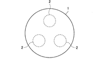
- FIG. 1 is a plan view illustrating an example of a plate member having a plurality of fastening portions.
- the plate-like member 1 has a substantially flat disk shape.
- the plate-like member 1 is bolted to another member at the fastening portion 2.
- the fastening strength is greatly influenced by the thickness of the plate-shaped member 1 near the fastening portion 2.
- the thickness is increased over the entire plate-like member, the weight of the plate-like member increases remarkably, and if there is a demand for weight reduction of the product provided with the plate-like member, this I can't respond to requests. Further, when the reinforcing plate is used, the number of parts increases, and the management cost and the assembly cost increase. Therefore, it is conceivable to increase the thickness of only the necessary portions (in the example of FIG. 1, the fastening portion 2 and the surrounding portions thereof) of the plate-like member (hereinafter also referred to as “thickening”). It is done.
- Patent Document 1 discloses a thickening press working method including a pre-process for deep-drawing a workpiece and a press-working process for thickening a predetermined portion with respect to the work after processing. Yes.
- Patent Document 2 a bent part is clamped from the outer periphery of the work against a press-made work having an end wall and a bent part bent to one side from the outer periphery of the end wall, and then in the radial direction.
- a method of increasing the thickness by compressing is disclosed.
- Patent Document 3 discloses a method of manufacturing a molded part having a bent corner, and a method of manufacturing a molded part having a thickening step of increasing the thickness of the corner by pressure molding. ing.
- Patent Documents 1 to 3 increase the thickness of a bent portion or a portion adjacent to an edge portion in a plate-like member, and other portions such as a fastening portion shown in FIG. As shown in FIG. 2, it cannot be applied to the case where the region separated from the peripheral portion is thickened in a portion that is substantially flat (that is, not bent).
- Patent Documents 1 to 3 show a method of increasing the thickness of a plurality of regions (fastening portions and surrounding portions) along the circumferential direction with respect to the center as in the plate-like member 1 shown in FIG. Not.
- the present invention has been made in view of the above problems, and the object of the present invention is to provide a novel and thickened portion in a region separated from the edge portion in a substantially flat plate-like portion.
- An object is to provide an improved plate-like molded body and a method for producing the same.
- a method for manufacturing a plate-shaped molded body having a plurality of thickened portions is a method for manufacturing a plate-shaped molded body having a plurality of thickened portions. At least a drawing step of drawing a cylindrical drawing body having a flat plate portion and a cylindrical drawing portion having a circular top portion that swells so as to protrude from the flat plate portion.
- a first step of forming a concave curved portion in the plate-shaped member by pressing a region of the plate-shaped plate member spaced from the edge with a first mold and a second mold; The outer peripheral portion of the plate-like member is sandwiched between the third die and the fourth die while the region including the concave curved portion in the member is sandwiched between the first and second dies. Relatively moving the first and second molds and the third and fourth molds; More, the area including the concave curve portion, is protruded to the outer peripheral portion, and a second step of obtaining the cylindrical aperture formed body.
- the concave curved portion is formed in a region corresponding to the top portion
- the second step includes setting a plurality of planned thickening regions along a circumferential direction with respect to a specific center while including at least a part of the concave curved portion, In a cross section that is perpendicular to the flat plate portion and includes the specific center, it may be formed by drawing so that the actual length of the increased thickness region is longer than the actual length of the increased thickness portion in the plate-shaped molded body.
- the concave curved portion further includes an annular groove-shaped curved portion that is formed around the hole-shaped curved portion so as to form a polygon as a whole when viewed perpendicular to the flat plate portion, and is curved in a groove shape. May be.
- the concave curved portion may include an annular groove-shaped curved portion that is formed so as to form a polygon as a whole when viewed perpendicularly to the flat plate portion and is curved in a groove shape.
- the thickened portion has a plate thickness of a thickness increase rate of 20% or more with respect to an initial plate thickness which is a plate thickness of the cylindrical drawn molded body, and is 5 times or more of the initial plate thickness in the cross section. It may have a length.
- a plate-like molded body having a plurality of thickened portions, which swells so as to protrude from the flat plate portion and the flat plate portion, and has a circular shape. And a reduced-thickness that is less than the reference plate thickness when the reference plate thickness is t [mm].
- a plate-like molded body is provided in which the plate thickness td [mm] of the part satisfies the following relational expression.
- FIG. 1 is a plan view showing an example of a plate-like member.
- FIG. 2 is a perspective view of a cylindrical drawn body formed and used in the first embodiment.
- FIG. 3A is a cross-sectional view for explaining a drawing process in the first embodiment.
- FIG. 3B is a cross-sectional view for explaining a drawing process in the first embodiment.
- FIG. 3C is a cross-sectional view for explaining a drawing process in the first embodiment.
- FIG. 3D is a cross-sectional view for explaining a drawing process in the first embodiment.
- FIG. 4A is a cross-sectional view for explaining a process of deforming the cylindrical throttle portion toward the central axis and increasing the thickness of the portion around the concave curved portion in the first embodiment.
- FIG. 4A is a cross-sectional view for explaining a process of deforming the cylindrical throttle portion toward the central axis and increasing the thickness of the portion around the concave curved portion in the first embodiment.
- FIG. 4B is a cross-sectional view for explaining a process of deforming the cylindrical throttle portion toward the central axis and increasing the thickness of the portion around the concave curved portion in the first embodiment.
- FIG. 4C is a cross-sectional view for explaining a process of deforming the cylindrical throttle portion toward the central axis side and increasing the thickness of the portion around the concave curved portion in the first embodiment.
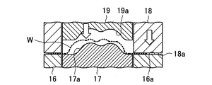
- FIG. 4D is a cross-sectional view for explaining a process of deforming the cylindrical throttle portion toward the central axis side and increasing the thickness of the portion around the concave curved portion in the first embodiment.
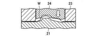
- FIG. 5A is a cross-sectional view for explaining a main thickening step in the first embodiment.
- FIG. 5B is a cross-sectional view for explaining a main thickening step in the first embodiment.
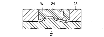
- FIG. 5C is a cross-sectional view for explaining a main thickening process in the first embodiment.
- FIG. 5D is a cross-sectional view for explaining a main thickening process in the first embodiment.
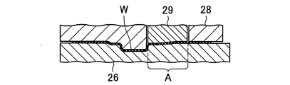
- FIG. 6A is a cross-sectional view for explaining a step of adjusting the thickness of the planned thickness increase region in the first embodiment.
- FIG. 6B is a cross-sectional view for explaining a step of adjusting the thickness of the planned thickness increase region in the first embodiment.
- FIG. 6C is a cross-sectional view for explaining a step of adjusting the thickness of the planned increase in thickness in the first embodiment.
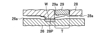
- FIG. 6D is a cross-sectional view for explaining a step of adjusting the thickness of the planned thickness increase region in the first embodiment.
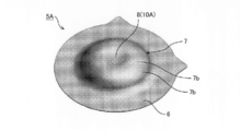
- FIG. 7 is a perspective view of a cylindrical drawn body formed and used in the second embodiment.
- FIG. 8A is a cross-sectional view for explaining a drawing process in the second embodiment.
- FIG. 8B is a cross-sectional view for explaining a drawing process in the second embodiment.
- FIG. 8C is a cross-sectional view for explaining a drawing process in the second embodiment.
- FIG. 8D is a cross-sectional view for explaining a drawing process in the second embodiment.
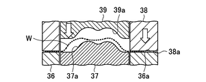
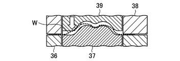
- FIG. 9A is a cross-sectional view for explaining a step of deforming the cylindrical throttle portion toward the central axis and increasing the thickness of the portion around the concave curved portion in the second embodiment.
- FIG. 9B is a cross-sectional view for explaining a process of deforming the cylindrical throttle portion toward the central axis and increasing the thickness of the portion around the concave curved portion in the second embodiment.
- FIG. 9C is a cross-sectional view for explaining a process of deforming the cylindrical throttle portion toward the central axis and increasing the thickness of the portion around the concave curved portion in the second embodiment.
- FIG. 9A is a cross-sectional view for explaining a step of deforming the cylindrical throttle portion toward the central axis and increasing the thickness of the portion around the concave curved portion in the second embodiment.
- FIG. 9B is a cross-sectional view for explaining a process of deforming the cylindrical throttle portion toward the central axis and increasing the thickness of the portion around the concave curved portion in
- 9D is a cross-sectional view for explaining a process of deforming the cylindrical throttle portion toward the central axis and increasing the thickness of the portion around the concave curved portion in the second embodiment.
- the relationship between the reference plate thickness of the cylindrical drawn body t [mm], the plate thickness ti [mm] of the increased thickness portion, and the plate thickness td [mm] of the reduced thickness portion reduced from the reference plate thickness is shown.
- the method for producing a plate-like molded body having a plurality of thickened portions is as follows.
- a planned increase in thickness is set so that the actual length of the increase in thickness region is longer than the actual length of the increased thickness portion in the plate-shaped body.
- a drawing process for drawing While increasing the actual length of each thickening planned area of the cross section, finally, the cylindrical drawing formed body is increased so that the thickening planned area and the flat plate portion are flattened as a whole.
- the meat process including.
- actual length refers to the length along the surface of the object in a predetermined cross section of the object.
- the thickening step may include a plurality of steps of pressing the cylindrical draw formed body so that the actual length of each thickening scheduled region of the cross section is shortened. In this case, at least of these plural steps, In one process, the planned thickness increase region and the flat plate portion can be made flat as a whole.
- the material of the plate member is not particularly limited, but can be, for example, a high-tensile steel plate having a tensile strength of 390 MPa or more, and may be a high-tensile steel plate having a tensile strength of 440 MPa or more, for example.
- the plate-like molded body manufactured by this manufacturing method can be, for example, a drive system component or a suspension mounting component.
- the thickened portion can be a portion for fastening the bolt.
- a plate-like molded body in which three thickened portions are formed around the center for example, a plate-like member 1 shown in FIG. To do.
- FIG. 2 is a perspective view of a cylindrical drawn body formed in the drawing process.
- the cylindrical drawn body 5 obtained in this step includes a flat plate portion 6 and a cylindrical drawn portion 7 swelled so as to protrude with respect to the flat plate portion 6.
- the cylindrical diaphragm portion 7 has a dome shape and is substantially circular when viewed perpendicularly to the flat plate portion 6.
- the cylindrical throttle portion 7 has an annular side portion 7a rising from the flat plate portion 6 and a circular top portion 7b.
- a concave curved portion 10 including a hole-shaped curved portion 8 curved in a hole shape and an annular groove-shaped curved portion 9 formed around the hole-shaped curved portion 8 and curved in a groove shape is formed on the top portion 7b. Yes.
- the annular groove-shaped curved portion 9 is substantially a regular triangle when viewed perpendicularly to the flat plate portion 6. In this embodiment, a triangular annular groove-shaped curved portion 9 is formed corresponding to the formation of three thickened portions. In the case of forming N thickened portions, an N-shaped annular groove-shaped curved portion is formed. In this embodiment, a single (one) annular groove-shaped curved portion 9 is formed around the hole-shaped curved portion 8, but a double or more annular groove-shaped curved portion may be formed.
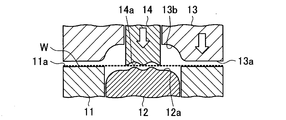
- 3A to 3D are cross-sectional views for explaining the drawing process.
- the lower die (blank holder) 11 and the punch 12 are paired with these members 11 and 12, and the upper die 13 and the pad 14 arranged above these are used for press molding ( By drawing, a cylindrical drawn body 5 that is an intermediate formed body is obtained.
- the lower die 11 is formed with a cylindrical hole penetrating in the vertical direction.
- the punch 12 is disposed in this hole. By moving the lower die 11 in the vertical direction, the relative positional relationship with the punch 12 changes.
- the upper surfaces of the lower die 11 and the punch 12 form a pressing surface 11a and a pressing surface 12a, respectively.
- the upper die 13 is formed with a columnar hole extending in the vertical direction and having a smaller width than the hole of the lower die 11.
- the pad 14 is disposed in the hole, and is attached to the upper die 13 via a press spring or a gas cylinder, and is movable along the axial direction of the hole.
- the outer peripheral portion forms a pressing surface 13 a and faces the pressing surface 11 a of the lower die 11, and the inner peripheral portion forms a pressing surface 13 b and the outer periphery of the pressing surface 12 a of the punch 12. Facing the part.
- the lower surface of the pad 14 forms a press surface 14 a and faces the central portion of the press surface 12 a of the punch 12.
- a load is applied to the pad 14 from the upper die 13 via a press spring or a gas cylinder. When such a load is not applied, the lower end of the pad 14 is at a position slightly lower than the height of the pressing surface 13a.
- the pressing surface 11a of the lower die 11 and the pressing surface 13a of the upper die 13 are flat.
- the press surface 14a of the pad 14 and the region of the press surface 12a of the punch 12 facing the press surface 14a have a shape corresponding to the concave curved portion 10 (see FIG. 2) of the cylindrical drawn body 5.
- the press surface 13b and the region facing the press surface 13b in the press surface 12a have shapes corresponding to portions other than the concave curved portion 10 in the cylindrical diaphragm portion 7.
- the height of the pressing surface 11a of the lower die 11 and the height of the upper end of the pressing surface 12a of the punch 12 are substantially the same, for example, the pressing surface 11a and the pressing surface 12a.
- the lower die 11 and the upper die 13 sandwich the workpiece W with a cushioning force in the case of a single-acting press machine and an outer load in the case of a double-acting press machine (in the case of a single-acting press).
- the lower die 11 and the upper die 13 apply a force in the in-plane direction (referred to as “blank hold force” or “wrinkle holding force”) to the workpiece W so that the workpiece W can move relative to the workpiece W.
- blade hold force or “wrinkle holding force”
- the upper die 13 is moved downward.
- the pad 14 mounted on the upper die 13 also moves downward, and the lower end of the upper die 13 first contacts the workpiece W.
- the upper die 13 is moved further downward, and the workpiece W is pressed by the punch 12 and the pad 14 by the pressure applied from the pad 14.
- the concave curved part 10 is formed in the center part of the workpiece
- work W (refer FIG. 3B).
- the height of the concave curved portion 10 in the workpiece W is substantially the same as the height of the remaining portion of the workpiece W, and the press of the upper die 13 on the press surface 13 b of the upper die 13 and the press surface 12 a of the punch 12.
- the region facing the surface 13b is substantially separated from the workpiece W.
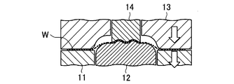
- the workpiece W is sandwiched between the punch 12 and the pad 14, and the upper die 13 is continuously moved downward to form a cylindrical surface portion on the workpiece W by drawing (see FIG. 3C).
- the workpiece W between the lower die 11 and the upper die 13 is narrowed to the inside, that is, the space between the outer peripheral portion of the press surface 12a and the press surface 13b. Since drawing is continued while the workpiece W is sandwiched between the punch 12 and the pad 14, almost no material flows out from between the punch 12 and the pad 14 in the outer peripheral direction. As a result, the thickness of the workpiece W in the space between the punch 12 and the pad 14 is hardly reduced.
- the workpiece W is appropriately pressed by the lower die 11 and the upper die 13, even if the workpiece W is pulled inward, the workpiece W is unlikely to be wrinkled.
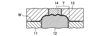
- the upper die 13 is continuously moved downward, and the workpiece W is pressed by the press surface 13b and the outer peripheral portion of the press surface 12a of the punch 12 (see FIG. 3D).
- the portion between the pressing surface 11a of the lower die 11 and the pressing surface 13a of the upper die 13 becomes the flat plate portion 6, and the press surface 12a of the punch 12 and the press surface 13b of the upper die 13
- the portion between the pad 14 and the press surface 14 a becomes the cylindrical diaphragm 7. In this way, the cylindrical drawn body 5 (see FIG. 2) is obtained.
- the planned thickening region T In the cross section shown in FIG. 3D, in the cylindrical drawn portion 7 of the workpiece W (cylindrical drawn molded body 5), approximately the right half is the planned thickening region T where the final thickening is planned.
- the planned thickness increase region T is set to a region including at least a part of the concave curved portion 10.
- three planned thickened regions T are set.
- the three thickening scheduled regions T are set so as to appear at approximately 120 ° intervals in the circumferential direction with respect to the center (specific center) of the hole-shaped curved portion 8 (see FIG. 2).
- the center of the hole-shaped curved portion 8 that forms the center of the plurality of planned thickening regions T may be at the center of the top portion 7b (on the central axis of the cylindrical throttle portion 7), and is at a position shifted from the center of the top portion 7b. May be.
- FIG. 8 shows a cross section passing through the center of FIG. 8 and perpendicular to the flat plate portion 6 (hereinafter referred to as “central cross section”). In these cross-sectional views, only one planned thickness increase region T of the three planned thickness increase regions T appears.
- the actual length of each thickening scheduled region T is made longer than the actual length of the thickened portion in the finished plate-shaped body.
- the workpiece W is pressed by the punch 12 and the pad 14, and the upper die 13 is continuously moved downward while the workpiece W is sandwiched between the punch 12 and the pad 14. Then, a cylindrical surface portion is formed on the workpiece W by drawing. For this reason, when the drawing is performed, the concave curved portion 10 is kept pressed by the punch 12 and the pad 14, so that the thickness of the workpiece W in the concave curved portion 10 is reduced during the molding process. There is nothing. Therefore, the thickness of the workpiece W can be ensured to the maximum before performing the next thickening step, and the thickening can be reliably performed.
- the lower die (blank holder) 16 and the punch 17 are paired with these members 16 and 17, and the first and second upper dies 18 and 19 disposed above these are used.
- the lower die 16 has a columnar hole penetrating in the vertical direction.
- the punch 17 is guided in the hole and is movable along the axial direction of the hole.
- the upper surfaces of the lower die 16 and the punch 17 form a pressing surface 16a and a pressing surface 17a, respectively.
- the first upper die 18 is formed with a columnar hole penetrating in the vertical direction and having substantially the same cross-sectional shape and size as the hole of the lower die 16.
- the second upper die 19 is guided in the hole and is movable along the axial direction of the hole.
- the lower surface of the first upper die 18 forms a pressing surface 18 a and faces the pressing surface 16 a of the lower die 16.
- the lower surface of the second upper die 19 forms a press surface 19 a and faces the press surface 17 a of the punch 17.
- the pressing surfaces 16a and 18a are flat.
- the center part of the press surfaces 17a and 19a has a dome shape whose diameter is smaller than that of the cylindrical throttle part 7.
- the outer peripheral part of the press surfaces 17a and 19a is a flat surface.
- the actual lengths of the press surfaces 17a and 19a are shorter than the actual lengths of the portions corresponding to the press surfaces 17a and 19a in the workpiece W which is the cylindrical drawn body 5.
- the actual length of the portion facing the concave curved portion 10 of the cylindrical drawn body 5 is particularly shorter than the actual length of the concave curved portion 10.
- the height of the pressing surface 16a of the lower die 16 and the height of the edge of the pressing surface 17a of the punch 17 are substantially the same, so that the pressing surface 16a and the pressing surface 17a
- the workpiece W that is the cylindrical drawn body 5 is placed at a predetermined position.
- the lower die 16 and the upper die 18 exert a wrinkle pressing force while sandwiching the workpiece W.
- the second upper die 19 is lowered and pressed against the workpiece W. Since the diameter of the dome-shaped portions of the press surfaces 17a and 19a is smaller than the diameter of the cylindrical throttle portion 7, the workpiece W is drawn so as to be moved toward the central axis (see FIG. 4B).
- the second upper die 19 is lowered. As a result, the workpiece W is narrowed down toward the central axis, and the second upper die 19 is pressed against the concave curved portion 10 of the workpiece W (see FIG. 4C). Then, the workpiece W is pressed by the punch 17 and the second upper die 19 (see FIG. 4D). Since the actual length of the press surfaces 17a and 19a is shorter than the actual length of the corresponding portion of the workpiece W in the central cross section, the actual length of the workpiece W, particularly the peripheral portion of the concave curved portion 10, is shortened and the thickness is increased.
- 5A to 5D are cross-sectional views for explaining this process.
- the lower die 21 and the first and second upper dies 23 and 24 disposed above the lower die 21 are used.
- a columnar hole penetrating in the vertical direction is formed in the first upper die 23.
- the second upper die 24 is guided in the hole and is movable along the axial direction of the hole.
- a truncated cone-shaped protrusion 21P is formed on the upper portion of the lower die 21.
- the upper surface of the lower die 21 forms a press surface 21a.
- the press surface 21a there is a downwardly inclined region in the direction away from the protruding portion 21P around the protruding portion 21P, and there is a flat region on the substantially same plane around the downwardly inclined region.
- the lower surface of the second upper die 24 forms a press surface 24a, and faces the surface of the protruding portion 21P and the downward inclined region on the press surface 21a.
- the lower surface of the first upper die 23 forms a flat pressing surface 23a and faces a flat region on the pressing surface 21a.
- a part of the downward sloping area on the press surface 21a and the corresponding area on the press surface 24a correspond to the planned thickness increase area T of the workpiece W.
- the planned increase in thickness T of the workpiece W is greatly curved upward, whereas the corresponding areas of the press surfaces 21a and 24a are substantially flat. Therefore, in the central cross section, the actual length of the planned thickness increase region T is longer than the actual length of the corresponding region of the press surfaces 21a and 24a.
- the actual length of the area corresponding to the planned increase area T of the press surfaces 21a and 24a is shorter than the actual length of the expected increase area T, so that the actual length of the expected increase area T is shortened by this pressing.
- the workpiece W is deformed (see FIGS. 5B to 5D).
- region T is thickened and becomes flat.
- the planned increase in thickness T includes a portion (see FIGS. 4A to 4D) that is thickened by pressing the concave curved portion 10, the planned increase in thickness T is compared to the initial thickness of the workpiece W. Remarkably increases the thickness.
- the increase in thickness is not as large as in the expected increase in thickness area T.
- 6A to 6D are cross-sectional views for explaining this process.
- the molding is carried out after the molded body of the previous process (FIGS. 5A to 5D) is reversed by a conveyor or the like.
- the lower die 26 and the first and second upper dies 28 and 29 disposed above the lower die 26 are used.
- a columnar hole penetrating in the vertical direction is formed in the first upper die 28.
- the second upper die 29 is guided in the hole and is movable along the axial direction of the hole.
- the upper surface of the lower die 26 forms a press surface 26a.
- the lower surfaces of the first and second upper dies 28 and 29 form press surfaces 28a and 29a, respectively.
- the shape of the press surface 26a is substantially the same as that of the press surface 23a and the press surface 24a shown in FIG. 5A, which are turned upside down and the actual length of the cross section is slightly shorter than that of FIG. 5A. It is set.
- the shape of the press surfaces 28a and 29a is substantially the same as that of the press surface 21a shown in FIG.
- the protrusion 21P (see FIG. 5A) of the lower die 21 has a truncated cone shape as described above, whereas the protrusion 28P corresponding to the protrusion 21P in the first upper die 28 has a cylindrical shape. It is.
- a part of the region including a portion corresponding to the planned increase in thickness region T is different from the shape of the press surfaces 24a and 21a as described below.
- the area of the press surface 29a and the press surface 26a that faces the press surface 29a corresponds to the planned thickness increase area T of the workpiece W.
- the region corresponding to the planned increase in thickness T is inclined with respect to the flat portion on the outer periphery, whereas in the press surface 26a shown in FIG.
- the corresponding region is almost not inclined with respect to the flat portion on the outer periphery, and is almost on the same plane. Due to this difference, the planned thickness increase region T of the workpiece W shown in FIGS. 6A to 6D extends with an inclination with respect to the corresponding region of the press surfaces 26a, 29a.
- the actual length of the workpiece W is longer than the actual length of the press surfaces 26a and 29a.
- the workpiece W When adjusting the shape of the workpiece W and the thickness of the planned thickness increase region T, first, the workpiece W is turned upside down with respect to the state shown in FIG. The workpiece W is placed on the lower die 26 so as to be along. Then, the workpiece W is pressed by the lower die 26 and the first upper die 28. In the workpiece W, a portion formed into a truncated cone shape by the protruding portion 21P (see FIG. 5A) is reshaped into a cylindrical shape by the protruding portion 28P (see FIGS. 6B and 6C).
- the planned increase area T of the workpiece W is pressed by the lower die 26 and the second upper die 29.
- the actual length of the region corresponding to the planned increase in thickness region T of the press surface 26a and the actual length of the press surface 29a are shorter than the actual length of the planned increase in thickness region T.
- the actual length of T is shortened.
- the thickening scheduled region T is increased in thickness to become the thickened portion A, and the thickened portion A and the flat portion of the outer peripheral portion of the workpiece W (the flat plate portion 6 of the cylindrical drawn molded body 5) As shown in FIG. 6D.
- the other two thickening planned areas T not shown in the cross sections shown in FIGS. 3A to 6D are similarly thickened to become a thickened portion A.
- a plate-like molded body 40 having a plurality of thickened portions A in a region separated from the edge in a substantially flat portion is obtained.
- the main steps for shortening the actual length of the planned increase in thickness T in the central cross section are those shown in FIGS. 5A to 5D, but the steps shown in FIGS. 4A to 4D and FIGS. Also in the step shown in 6D, the actual length is shortened, and the planned thickness increase region T is increased.
- the process of finally making the overall thickness increase region T and the flat plate portion 6 (flat portion of the outer peripheral portion of the workpiece W) substantially flat as a whole is as shown in FIGS. 6A to 6D.
- the planned thickness increase region T and the flat plate portion 6 are made to approach a flat state as a whole.
- the cylindrical drawn body 5 used in the first embodiment is formed with the hole-shaped curved portion 8 and the annular groove-shaped curved portion 9, but the hole-shaped curved portion 8 and the annular groove-shaped curved portion. You may use the cylindrical drawing molded object in which only one of 9 was formed.
- FIG. 7 is a perspective view of a cylindrical drawn body. 7, parts corresponding to those shown in FIG. 2 are given the same reference numerals as those in FIG. Only the hole-shaped curved portion 8 is formed as the concave curved portion 10A on the top portion 7b of the cylindrical drawn body 5A, and the annular groove-shaped curved portion 9 (see FIG. 2) is not formed.
- FIGS. 8A to 8D are cross-sectional views for explaining the drawing process.
- a lower die (blank holder) 31 and a punch 32 are paired with these members 31 and 32, and an upper die 33 and a pad 34 disposed above these are used to perform press molding.
- a cylindrical drawn molded body 5A which is an intermediate molded body is obtained.
- the lower die 31, punch 32, upper die 33, and pad 34 have substantially the same configuration as the lower die 11, punch 12, upper die 13, and pad 14 shown in FIGS. 3A to 3D, respectively.
- the press surface 34a of the pad 34 and the region of the press surface 32a of the punch 32 that faces the press surface 34a have a shape corresponding to the concave curved portion 10A (see FIG. 7) of the cylindrical drawn body 5A. Yes.
- the workpiece W is placed on the pressing surface 31a such that the upper end of the pressing surface 32a is lower than the pressing surface 31a of the lower die 31. Then, the work W is sandwiched between the lower die 31 and the upper die 33.
- the upper die 33 is moved downward, and the workpiece W is pressed by the punch 32 and the pad 44 by the pressure applied from the pad 34 mounted on the upper die 33.
- the concave curved part 10A is formed in the center part of the workpiece W (see FIG. 8B).
- the height of the concave curved portion 10 ⁇ / b> A in the workpiece W is substantially the same as the height of the remaining portion of the workpiece W, and the press of the upper die 33 on the press surface 33 b of the upper die 33 and the press surface 32 a of the punch 32.
- the region facing the surface 33b is substantially separated from the workpiece W.
- the workpiece W is sandwiched between the punch 32 and the pad 34, and the upper die 33 is continuously moved downward to form a cylindrical surface portion on the workpiece W by drawing (see FIG. 8C).
- the workpiece W between the lower die 31 and the upper die 33 is narrowed to the inside, that is, the space between the outer peripheral portion of the press surface 32a and the press surface 33b.
- the upper die 33 is continuously moved downward, and the workpiece W is pressed by the press surface 33b and the outer peripheral portion of the press surface 32a of the punch 32 (see FIG. 8D).
- the portion between the pressing surface 31a of the lower die 31 and the pressing surface 33a of the upper die 33 becomes the flat plate portion 6, and the press surface 32a of the punch 32, the press surface 33b of the upper die 33,
- the portion between the pad 34 and the press surface 34 a of the pad 34 is a cylindrical diaphragm 7. In this way, a cylindrical drawn body 5A (see FIG. 7) is obtained.
- the planned thickening region T where the final thickening is planned.
- three thickening planned areas T are set.
- the three thickening scheduled regions T are set so as to appear at intervals of approximately 120 ° in the circumferential direction with respect to the center (specific center) of the hole-shaped curved portion 8 (see FIG. 7).
- the actual length of each thickening scheduled region T is made longer than the actual length of the thickened portion in the finished plate-shaped product.
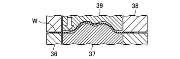
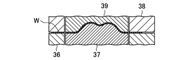
- the lower die 36 and the punch 37 are paired with the members 36 and 37, and the first and second upper dies 38 and 39 disposed above these are used.
- the lower die (blank holder) 36, the punch 37, the first upper die 38, and the second upper die 39 are respectively the lower die 16, the punch 17, the first upper die 18, and the second die shown in FIGS. 4A to 4D.
- the structure is almost the same as that of the upper die 19.
- the central portion of the press surface 37a of the punch 37 and the central portion of the press surface 39a of the second upper die 39 have a dome shape whose diameter is smaller than that of the cylindrical throttle portion 7.
- the actual lengths of the press surfaces 37a and 39a are shorter than the actual lengths of the portions corresponding to the press surfaces 37a and 39a in the workpiece W that is the cylindrical drawn body 5A.
- the actual length of the portion corresponding to the concave curved portion 10A of the cylindrical drawn body 5A is particularly shorter than the actual length of the concave curved portion 10A.
- the height of the pressing surface 36a of the lower die 36 and the height of the edge of the pressing surface 37a of the punch 37 are substantially the same so that the pressing surface 36a and the pressing surface 37a
- the workpiece W that is the cylindrical drawn body 5A is placed at a predetermined position. Then, the workpiece W is sandwiched between the lower die 36 and the first upper die 38.
- the second upper die 39 is lowered and pressed against the workpiece W. Since the diameter of the dome-shaped portions of the press surfaces 37a and 39a is smaller than the diameter of the cylindrical diaphragm 7, the workpiece W is deformed so as to be moved toward the central axis (see FIG. 9B).
- the second upper die 39 is lowered, the second upper die 39 is pressed against the concave curved portion 10A of the workpiece W (see FIG. 9C), and the workpiece W is pressed by the punch 37 and the second upper die 39 ( (See FIG. 9D). Since the actual length of the press surfaces 37a and 39a is shorter than the actual length of the corresponding portion of the workpiece W in the central section, the actual length of the workpiece W, particularly the peripheral portion of the concave curved portion 10A is shortened and the thickness is increased.
- the thickness increase rate of the planned thickness increase region T by the above steps is the same as in the steps shown in FIGS. 4B to 4D. It is smaller than the thickness increase rate of the planned thickness increase region T.
- the thickness increase rate of the thickened portion obtained by the manufacturing method of the second embodiment because the thickening by pressing the annular groove-shaped curved portion 9 is not obtained is the manufacturing method of the first embodiment. It becomes smaller than the thickness increase rate of the thickened part obtained by.
- the thickened portion has a thickness increase rate of 20% or more with respect to the initial plate thickness which is the plate thickness of the cylindrical drawn molded body, and is 5 times the initial plate thickness in the central cross section. It has the above length.
- the upper mold when pressing with the lower mold and the upper mold, instead of raising the lower mold, the upper mold may be lowered, instead of lowering the upper mold.
- the lower mold may be raised.
- the thickening step the actual length of the planned thickening region T is shortened while suppressing wrinkles caused by out-of-plane deformation during molding. Thereby, the thickening scheduled area
- region T is thickened and becomes a thickening part.
- the planned thickening region T and the flat plate portion are made flat as a whole. Therefore, according to this method, it is possible to produce a plate-like molded body having a thickened portion in a region separated from the edge portion in a substantially flat portion.
- a plurality of planned thickness increase regions T are set along the circumferential direction with respect to a specific center. For this reason, according to this method, it is possible to manufacture a plate-like molded body in which a plurality of thickened portions appear along the circumferential direction with respect to the center.
- the concave curved portion 10 has a longer actual length than a cross section having no concave curved portion. Since the thickening planned region T is formed in a region including at least a part of the concave curved portion 10, the concave curved portion 10 is thickened particularly thickly by pressing in the thickening planned region T. .
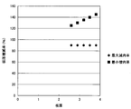
- FIG. 10 is a characteristic diagram showing the plate thickness of the cylindrical drawn compacts 5, 5A.
- the thickened portion A is thicker than the plate thickness before processing (reference plate thickness).
- material outflow from the space between the punch 12 and the pad 14 in the outer peripheral direction hardly occurs, but a slight thickness reduction may occur.
- a slight thinning occurs in a region where the thickness is not increased around the region suppressed by the pad 14. These thinned regions are referred to as thinned portions.
- the reference plate thickness is t [mm]
- the plate thickness ti [mm] of the thickened portion
- the plate thickness td of the thinned portion that is thinner than the reference plate thickness.
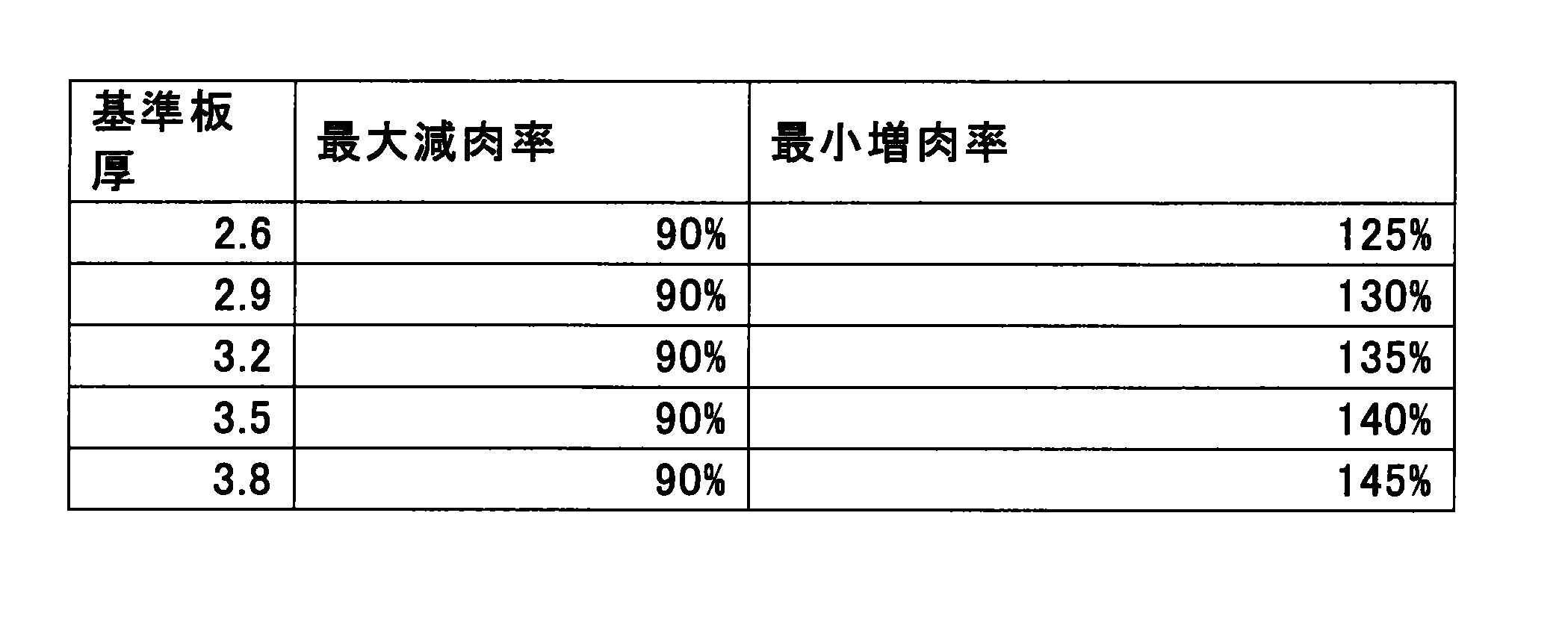
- the relationship shown in FIG. 10 and the following table was obtained between [mm].
- the reference plate thickness is a plate thickness in a region excluding the thickened portion and the thinned portion of the cylindrical drawn molded bodies 5 and 5A.
- the plate thickness ti [mm] of the thickened portion and the plate thickness td [mm] of the thinned portion are It is possible to mold a plate-shaped molded body that satisfies the following relational expression.
- ti ⁇ 1.25t When 3.0 ⁇ t ⁇ 4.0 td ⁇ 0.9t, ti ⁇ 1.35t, In the case of 4.0 ⁇ t ⁇ 5.0 td ⁇ 0.9t, ti ⁇ 1.45t
- the thickened portion increased with respect to the reference plate thickness and the thickness was slightly reduced with respect to the reference plate thickness according to the reference plate thickness.
- a thinned portion is formed.
- the maximum thinning rate in the thinned portion is about 90%, and it can be seen that the material outflow is minimized. Therefore, according to the above-described embodiment, molding is performed in a state where the material is sandwiched between the punch 12 and the pad 14, thereby minimizing the material outflow in the thinned portion and increasing the thickness by 25% or more in the thickened portion.
- the cylindrical drawn compacts 5 and 5A can be molded.
Landscapes
- Engineering & Computer Science (AREA)
- Mechanical Engineering (AREA)
- Shaping Metal By Deep-Drawing, Or The Like (AREA)
- Forging (AREA)
- Blow-Moulding Or Thermoforming Of Plastics Or The Like (AREA)
- Moulds For Moulding Plastics Or The Like (AREA)
Abstract
Description
前記第2の工程は、前記円筒絞り部に相当する領域において、前記凹湾曲部の少なくとも一部を含みつつ特定の中心に対して周方向に沿って複数の増肉予定領域を設定し、前記平板部に垂直で前記特定の中心を含む断面において、前記増肉予定領域の実長が前記板状成形体における前記増肉部の実長より長くなるように絞り成形するものであっても良い。
2.0<t<3.0の場合 td≧0.9t,ti≧1.25t
3.0<t<4.0の場合 td≧0.9t,ti≧1.35t
4.0<t<5.0の場合 td≧0.9t,ti≧1.45t
平板部と、前記平板部から突出するように膨らみ、円形の頂部を有する円筒絞り部とを備えた円筒絞り成形体を絞り成形により得る絞り成形工程であって、前記頂部に相当する領域に、穴状に湾曲した穴状湾曲部を含む凹湾曲部を形成し、前記円筒絞り部に相当する領域において、前記凹湾曲部の少なくとも一部を含みつつ特定の中心に対して周方向に複数の増肉予定領域を設定し、前記平板部に垂直で前記特定の中心を含む断面において、前記増肉予定領域の実長が前記板状成形体における前記増肉部の実長より長くなるように絞り成形する絞り成形工程と、
前記断面の各増肉予定領域の実長が短くなるようにしつつ、最終的に、前記増肉予定領域と前記平板部とを全体として平坦にするように、前記円筒絞り成形体をプレスする増肉工程と、
を含む。
〈第1の実施形態〉
この実施形態では、中心の周りに3つの増肉部が形成された板状成形体、たとえば、図1に示す板状部材1であって、締結部2およびその周辺を増肉したものを製造する。
この実施形態では、中心の周りに、3つの増肉部が形成された板状部材を製造する。
2.0<t<3.0の場合 td≧0.9t,ti≧1.25t
3.0<t<4.0の場合 td≧0.9t,ti≧1.35t
4.0<t<5.0の場合 td≧0.9t,ti≧1.45t
7b:頂部、 8:穴状湾曲部、 9:環溝状湾曲部、
10、10A:凹湾曲部、 11、31:下ダイ、 13、33:上ダイ、
12、32:パンチ、 14、34:パッド、 40:板状成形体、
A:増肉部、 T:増肉予定領域、 W:ワーク(被加工体)
Claims (8)
- 複数の増肉部を有する板状成形体の製造方法であって、
平板部と、前記平板部から突出するように膨らみ、円形の頂部を有する円筒絞り部とを備えた円筒絞り成形体を絞り成形により得る絞り成形工程を少なくとも備え、
前記絞り成形行程は、
平板状の板状部材における縁部から離間した領域を、第1の金型と第2の金型とでプレスして、前記板状部材に凹湾曲部を形成する第1の工程と、
前記板状部材における前記凹湾曲部を含む領域を、前記第1および第2の金型で挟んだまま、前記板状部材の外周部を、第3の金型と第4の金型とで挟み、前記第1および第2の金型と、前記第3および第4の金型とを相対的に移動させることにより、前記凹湾曲部を含む領域を、前記外周部に対して突出させて、前記円筒絞り成形体を得る第2の工程と
を備える、板状成形体の製造方法。 - 前記第1の工程は、前記頂部に相当する領域に前記凹湾曲部を形成し、
前記第2の工程は、前記円筒絞り部に相当する領域において、前記凹湾曲部の少なくとも一部を含みつつ特定の中心に対して周方向に沿って複数の増肉予定領域を設定し、前記平板部に垂直で前記特定の中心を含む断面において、前記増肉予定領域の実長が前記板状成形体における前記増肉部の実長より長くなるように絞り成形する、請求項1に記載の板状成形体の製造方法。 - 前記絞り成形工程の後、前記断面の各増肉予定領域の実長が短くなるようにしつつ、最終的に、前記増肉予定領域と前記平板部とを全体として平坦にするように、前記円筒絞り成形体をプレスする増肉工程を更に備える、請求項2に記載の板状成形体の製造方法。
- 前記凹湾曲部は、穴状に湾曲した穴状湾曲部を含む、請求項1~3のいずれかに記載の板状成形体の製造方法。
- 前記凹湾曲部が、前記平板部に垂直に見て全体として多角形をなすように前記穴状湾曲部の周囲に形成され溝状に湾曲した環溝状湾曲部をさらに含む、請求項4に記載の板状成形体の製造方法。
- 前記凹湾曲部は、前記平板部に垂直に見て全体として多角形をなすように形成され溝状に湾曲した環溝状湾曲部を含む、請求項1~3のいずれかに記載の板状成形体の製造方法。
- 前記増肉部が、前記円筒絞り成形体の板厚である初期板厚に対して20%以上の増肉率の板厚を有するとともに、前記断面において前記初期板厚の5倍以上の長さを有する、請求項1~6のいずれかに記載の板状成形体の製造方法。
- 複数の増肉部を有する板状成形体であって、
平板部と、
前記平板部から突出するように膨らみ、円形の頂部を有する円筒絞り部と、
を備え、
基準板厚をt[mm]とした場合に、前記増肉部の板厚ti[mm]、及び前記基準板厚よりも減肉された減肉部の板厚td[mm]が、以下の関係式を満たす、板状成形体。
2.0<t<3.0の場合 td≧0.9t,ti≧1.25t
3.0<t<4.0の場合 td≧0.9t,ti≧1.35t
4.0<t<5.0の場合 td≧0.9t,ti≧1.45t
Priority Applications (5)
| Application Number | Priority Date | Filing Date | Title |
|---|---|---|---|
| JP2016510569A JP6179665B2 (ja) | 2014-03-28 | 2015-03-27 | 複数の増肉部分を有する板状成形体の製造方法及び複数の増肉部を有する板状成形体 |
| US15/112,072 US10464116B2 (en) | 2014-03-28 | 2015-03-27 | Method of manufacturing plate-like molded body having a plurality of thickened portions, and plate-like molded body having a plurality of thickened portions |
| CN201580015372.4A CN106102948B (zh) | 2014-03-28 | 2015-03-27 | 具有多个增厚部分的板状成型体的制造方法及具有多个增厚部的板状成型体 |
| MX2016009371A MX374461B (es) | 2014-03-28 | 2015-03-27 | Método para manufacturar un componente formado en forma de lamina teniendo multiples secciones de grosor incrementado, y componente formado en forma de lamina teniendo multiples secciones de grosor incrementado. |
| KR1020167025415A KR101929643B1 (ko) | 2014-03-28 | 2015-03-27 | 복수의 두께 증가 부분을 갖는 판상 성형체의 제조 방법 및 복수의 두께 증가부를 갖는 판상 성형체 |
Applications Claiming Priority (2)
| Application Number | Priority Date | Filing Date | Title |
|---|---|---|---|
| JP2014069162 | 2014-03-28 | ||
| JP2014-069162 | 2014-03-28 |
Publications (1)
| Publication Number | Publication Date |
|---|---|
| WO2015147297A1 true WO2015147297A1 (ja) | 2015-10-01 |
Family
ID=54195801
Family Applications (1)
| Application Number | Title | Priority Date | Filing Date |
|---|---|---|---|
| PCT/JP2015/059764 Ceased WO2015147297A1 (ja) | 2014-03-28 | 2015-03-27 | 複数の増肉部分を有する板状成形体の製造方法及び複数の増肉部を有する板状成形体 |
Country Status (6)
| Country | Link |
|---|---|
| US (1) | US10464116B2 (ja) |
| JP (1) | JP6179665B2 (ja) |
| KR (1) | KR101929643B1 (ja) |
| CN (1) | CN106102948B (ja) |
| MX (1) | MX374461B (ja) |
| WO (1) | WO2015147297A1 (ja) |
Cited By (3)
| Publication number | Priority date | Publication date | Assignee | Title |
|---|---|---|---|---|
| EP3199256A1 (en) * | 2016-01-29 | 2017-08-02 | Kabushiki Kaisha Kobe Seiko Sho (Kobe Steel, Ltd.) | Manufacturing method of press-formed article, press-formed article, and press forming apparatus |
| JP2018176165A (ja) * | 2017-04-03 | 2018-11-15 | 東洋製罐株式会社 | シェルの製造方法、缶蓋の製造方法、シェル及び缶蓋 |
| CN115214782A (zh) * | 2021-04-16 | 2022-10-21 | 广州汽车集团股份有限公司 | 一种侧围a柱末端结构 |
Families Citing this family (9)
| Publication number | Priority date | Publication date | Assignee | Title |
|---|---|---|---|---|
| CA3011213C (en) * | 2016-01-26 | 2020-05-12 | Nippon Steel Corporation | A pressing machine and a method for manufacturing a press-formed product |
| JP6721544B2 (ja) * | 2017-06-28 | 2020-07-15 | 株式会社神戸製鋼所 | プレス成形品の製造方法 |
| CN108296349B (zh) * | 2018-01-15 | 2020-01-21 | 太原理工大学 | 一种镁合金板增厚的方法及装置 |
| JP7100878B2 (ja) * | 2018-01-26 | 2022-07-14 | 株式会社カネミツ | 金属板の加工方法 |
| CN108856513A (zh) * | 2018-07-08 | 2018-11-23 | 苏州华吉威自动化设备有限公司 | 一种折弯冲压模具 |
| CA3135330C (en) * | 2019-03-28 | 2023-06-27 | Honda Motor Co., Ltd. | Press forming method |
| CN114101474B (zh) * | 2020-08-31 | 2024-05-14 | 宝山钢铁股份有限公司 | 一种模组背板凸包二道次成形加工方法 |
| US12533138B2 (en) | 2021-04-20 | 2026-01-27 | Coherex Medical, Inc. | Occlusive material for medical device, system, and method thereof |
| KR20230082462A (ko) * | 2021-12-01 | 2023-06-08 | 주식회사 엘지에너지솔루션 | 파우치형 전지의 프리 폴딩장치 |
Citations (5)
| Publication number | Priority date | Publication date | Assignee | Title |
|---|---|---|---|---|
| JPS61199524A (ja) * | 1985-02-28 | 1986-09-04 | Nissan Motor Co Ltd | プレス成形方法 |
| US20070006628A1 (en) * | 2004-04-16 | 2007-01-11 | Youichi Tabei | Molding method by forging and molding method for case |
| JP2009012044A (ja) * | 2007-07-05 | 2009-01-22 | Nippon Steel Corp | 薄板のプレス金型装置及びプレス成形方法 |
| JP2010120062A (ja) * | 2008-11-20 | 2010-06-03 | Nissan Motor Co Ltd | プレス成形品の製造方法および製造装置、並びにプレス成形品 |
| JP2013018016A (ja) * | 2011-07-11 | 2013-01-31 | Kojuro Shinozaki | プレスによる寸法圧縮加工方法及び増厚加工方法 |
Family Cites Families (21)
| Publication number | Priority date | Publication date | Assignee | Title |
|---|---|---|---|---|
| US22763A (en) * | 1859-01-25 | Herman winter | ||
| US3481175A (en) * | 1968-01-11 | 1969-12-02 | Maytag Co | Method of forming and perforating a container |
| JP2714179B2 (ja) | 1989-09-22 | 1998-02-16 | 富士重工業株式会社 | プレス型の加工方法 |
| DE4294860T1 (de) * | 1992-04-20 | 1994-04-28 | Kanemitsu Akashi Kk | Verfahren zur Herstellung eines Drehkörpers aus einer Metallplatte |
| US5749257A (en) * | 1994-11-09 | 1998-05-12 | Aluminum Company Of America | Rivet in a converted can end, method of manufacture, and tooling |
| JP3594845B2 (ja) | 1999-08-10 | 2004-12-02 | 株式会社不二越 | 増肉プレス加工法 |
| US6539767B2 (en) * | 2000-08-31 | 2003-04-01 | Sequa Can Machinery, Inc. | Method and apparatus for forming a container component |
| DE602005007589D1 (de) * | 2004-02-27 | 2008-07-31 | Research In Motion Ltd | System und verfahren zum asynchronen kommunizieren mit synchronen web-diensten unter verwendung eines vermittlerdienstes |
| JP4522378B2 (ja) | 2005-04-20 | 2010-08-11 | ジヤトコ株式会社 | プレス成形方法及びその装置 |
| JP2006346703A (ja) | 2005-06-15 | 2006-12-28 | Kato Seisakusho:Kk | プレス加工方法 |
| CN100427235C (zh) | 2005-12-01 | 2008-10-22 | 日产自动车株式会社 | 具有角部的压力成形构件及其制造设备和制造方法 |
| JP4697086B2 (ja) | 2005-12-01 | 2011-06-08 | 日産自動車株式会社 | 屈曲した角部を有する成形部品およびその製造方法並びに製造装置 |
| US20090272171A1 (en) * | 2008-05-05 | 2009-11-05 | Ford Global Technologies, Llc | Method of designing and forming a sheet metal part |
| JP5237179B2 (ja) | 2009-04-17 | 2013-07-17 | 株式会社ユタカ技研 | プレス製ワークの部分増肉方法及びその増肉装置 |
| JP5416498B2 (ja) * | 2009-07-23 | 2014-02-12 | 本田技研工業株式会社 | テーラードブランク板の成形方法及びその装置 |
| EP2558229A1 (en) * | 2010-04-13 | 2013-02-20 | Crown Packaging Technology, Inc. | Can manufacture |
| CN104690137B (zh) * | 2011-01-14 | 2017-05-24 | 株式会社神户制钢所 | 钢板的冲压成形方法 |
| CN102716963A (zh) | 2012-06-08 | 2012-10-10 | 燕山大学 | 一种金属板材背压拉深成形方法及模具 |
| MX354007B (es) * | 2012-11-09 | 2018-02-08 | Nippon Steel & Sumitomo Metal Corp | Método de moldeo a presión. |
| WO2015079644A1 (ja) * | 2013-11-28 | 2015-06-04 | 新日鐵住金株式会社 | 鋼板素材、その製造方法及び製造装置、並びにその鋼板素材を用いたプレス成形品の製造方法 |
| KR101869177B1 (ko) * | 2013-12-26 | 2018-06-19 | 신닛테츠스미킨 카부시키카이샤 | 모자형 단면 부품의 제조 방법 |
-
2015
- 2015-03-27 WO PCT/JP2015/059764 patent/WO2015147297A1/ja not_active Ceased
- 2015-03-27 JP JP2016510569A patent/JP6179665B2/ja active Active
- 2015-03-27 US US15/112,072 patent/US10464116B2/en active Active
- 2015-03-27 KR KR1020167025415A patent/KR101929643B1/ko active Active
- 2015-03-27 CN CN201580015372.4A patent/CN106102948B/zh active Active
- 2015-03-27 MX MX2016009371A patent/MX374461B/es active IP Right Grant
Patent Citations (5)
| Publication number | Priority date | Publication date | Assignee | Title |
|---|---|---|---|---|
| JPS61199524A (ja) * | 1985-02-28 | 1986-09-04 | Nissan Motor Co Ltd | プレス成形方法 |
| US20070006628A1 (en) * | 2004-04-16 | 2007-01-11 | Youichi Tabei | Molding method by forging and molding method for case |
| JP2009012044A (ja) * | 2007-07-05 | 2009-01-22 | Nippon Steel Corp | 薄板のプレス金型装置及びプレス成形方法 |
| JP2010120062A (ja) * | 2008-11-20 | 2010-06-03 | Nissan Motor Co Ltd | プレス成形品の製造方法および製造装置、並びにプレス成形品 |
| JP2013018016A (ja) * | 2011-07-11 | 2013-01-31 | Kojuro Shinozaki | プレスによる寸法圧縮加工方法及び増厚加工方法 |
Cited By (6)
| Publication number | Priority date | Publication date | Assignee | Title |
|---|---|---|---|---|
| EP3199256A1 (en) * | 2016-01-29 | 2017-08-02 | Kabushiki Kaisha Kobe Seiko Sho (Kobe Steel, Ltd.) | Manufacturing method of press-formed article, press-formed article, and press forming apparatus |
| JP2017131960A (ja) * | 2016-01-29 | 2017-08-03 | 株式会社神戸製鋼所 | プレス成形品の製造方法、プレス成形品及びプレス成形装置 |
| US10300519B2 (en) | 2016-01-29 | 2019-05-28 | Kobe Steel, Ltd. | Manufacturing method of press-formed article, press-formed article, and press forming apparatus |
| JP2018176165A (ja) * | 2017-04-03 | 2018-11-15 | 東洋製罐株式会社 | シェルの製造方法、缶蓋の製造方法、シェル及び缶蓋 |
| CN115214782A (zh) * | 2021-04-16 | 2022-10-21 | 广州汽车集团股份有限公司 | 一种侧围a柱末端结构 |
| CN115214782B (zh) * | 2021-04-16 | 2023-08-15 | 广州汽车集团股份有限公司 | 一种侧围a柱末端结构 |
Also Published As
| Publication number | Publication date |
|---|---|
| KR20160120767A (ko) | 2016-10-18 |
| MX2016009371A (es) | 2016-10-13 |
| US10464116B2 (en) | 2019-11-05 |
| US20160332205A1 (en) | 2016-11-17 |
| JP6179665B2 (ja) | 2017-08-16 |
| KR101929643B1 (ko) | 2018-12-14 |
| CN106102948A (zh) | 2016-11-09 |
| MX374461B (es) | 2025-03-06 |
| JPWO2015147297A1 (ja) | 2017-04-13 |
| CN106102948B (zh) | 2018-01-26 |
Similar Documents
| Publication | Publication Date | Title |
|---|---|---|
| JP6179665B2 (ja) | 複数の増肉部分を有する板状成形体の製造方法及び複数の増肉部を有する板状成形体 | |
| CN105246611B (zh) | 成形材料制造方法 | |
| WO2015194401A1 (ja) | 冷間プレス成形(cold press forming)方法 | |
| JPWO2015199231A1 (ja) | プレス成形品の製造方法およびプレス金型 | |
| KR20190083643A (ko) | 비드형 캔 단부를 형성하기 위한 방법 및 장치 | |
| JP2017196632A (ja) | バーリング加工装置、バーリング加工方法、及びバーリング成形品 | |
| JP6429095B2 (ja) | 缶端部の被成形部の制御された薄肉化を伴って缶端部を形成するための方法および装置 | |
| JP5807293B2 (ja) | アンダーカット部の成形方法およびアンダーカット部を有する成形品の製造方法 | |
| US20250010353A1 (en) | Square can manufacturing method and square can manufacturing apparatus | |
| US20150050104A1 (en) | Method and apparatus for forming a can end with controlled thinning of formed portions of the can end | |
| JP6187238B2 (ja) | プレス成形方法及びプレス成形装置 | |
| JP2004322104A (ja) | 絞り成形金型および絞り成形方法 | |
| US20250010352A1 (en) | Square can manufacturing method and square can manufacturing apparatus | |
| KR101841233B1 (ko) | 성형제품에 볼트부 또는 너트부 성형을 위한 프레스 금형 | |
| RU61608U1 (ru) | Устройство для отбортовки отверстия | |
| JP2018176165A (ja) | シェルの製造方法、缶蓋の製造方法、シェル及び缶蓋 | |
| JP2023128492A (ja) | 鍛造用パンチおよび金型 | |
| JP2012196707A (ja) | ワークの成形方法 | |
| JPH04258339A (ja) | フランジ部材の塑性加工方法 | |
| JP2011224603A (ja) | 弾性プレス金型及び弾性プレス方法 | |
| JP2018114510A (ja) | ドグ歯鍛造成形方法 | |
| CN1970188A (zh) | 拉延方法及拉延模具 |
Legal Events
| Date | Code | Title | Description |
|---|---|---|---|
| 121 | Ep: the epo has been informed by wipo that ep was designated in this application |
Ref document number: 15768227 Country of ref document: EP Kind code of ref document: A1 |
|
| ENP | Entry into the national phase |
Ref document number: 2016510569 Country of ref document: JP Kind code of ref document: A |
|
| WWE | Wipo information: entry into national phase |
Ref document number: 15112072 Country of ref document: US |
|
| WWE | Wipo information: entry into national phase |
Ref document number: MX/A/2016/009371 Country of ref document: MX |
|
| ENP | Entry into the national phase |
Ref document number: 20167025415 Country of ref document: KR Kind code of ref document: A |
|
| WWE | Wipo information: entry into national phase |
Ref document number: IDP00201606275 Country of ref document: ID |
|
| NENP | Non-entry into the national phase |
Ref country code: DE |
|
| 122 | Ep: pct application non-entry in european phase |
Ref document number: 15768227 Country of ref document: EP Kind code of ref document: A1 |