WO2015147280A1 - 全固体二次電池、電池用電極シートの製造方法および全固体二次電池の製造方法 - Google Patents
全固体二次電池、電池用電極シートの製造方法および全固体二次電池の製造方法 Download PDFInfo
- Publication number
- WO2015147280A1 WO2015147280A1 PCT/JP2015/059678 JP2015059678W WO2015147280A1 WO 2015147280 A1 WO2015147280 A1 WO 2015147280A1 JP 2015059678 W JP2015059678 W JP 2015059678W WO 2015147280 A1 WO2015147280 A1 WO 2015147280A1
- Authority
- WO
- WIPO (PCT)
- Prior art keywords
- solid electrolyte
- active material
- electrode active
- material layer
- layer
- Prior art date
- Legal status (The legal status is an assumption and is not a legal conclusion. Google has not performed a legal analysis and makes no representation as to the accuracy of the status listed.)
- Ceased
Links
Images



Classifications
-
- H—ELECTRICITY
- H01—ELECTRIC ELEMENTS
- H01M—PROCESSES OR MEANS, e.g. BATTERIES, FOR THE DIRECT CONVERSION OF CHEMICAL ENERGY INTO ELECTRICAL ENERGY
- H01M10/00—Secondary cells; Manufacture thereof
- H01M10/05—Accumulators with non-aqueous electrolyte
- H01M10/056—Accumulators with non-aqueous electrolyte characterised by the materials used as electrolytes, e.g. mixed inorganic/organic electrolytes
- H01M10/0561—Accumulators with non-aqueous electrolyte characterised by the materials used as electrolytes, e.g. mixed inorganic/organic electrolytes the electrolyte being constituted of inorganic materials only
- H01M10/0562—Solid materials
-
- B—PERFORMING OPERATIONS; TRANSPORTING
- B05—SPRAYING OR ATOMISING IN GENERAL; APPLYING FLUENT MATERIALS TO SURFACES, IN GENERAL
- B05C—APPARATUS FOR APPLYING FLUENT MATERIALS TO SURFACES, IN GENERAL
- B05C9/00—Apparatus or plant for applying liquid or other fluent material to surfaces by means not covered by any preceding group, or in which the means of applying the liquid or other fluent material is not important
- B05C9/06—Apparatus or plant for applying liquid or other fluent material to surfaces by means not covered by any preceding group, or in which the means of applying the liquid or other fluent material is not important for applying two different liquids or other fluent materials, or the same liquid or other fluent material twice, to the same side of the work
-
- H—ELECTRICITY
- H01—ELECTRIC ELEMENTS
- H01M—PROCESSES OR MEANS, e.g. BATTERIES, FOR THE DIRECT CONVERSION OF CHEMICAL ENERGY INTO ELECTRICAL ENERGY
- H01M10/00—Secondary cells; Manufacture thereof
- H01M10/05—Accumulators with non-aqueous electrolyte
- H01M10/052—Li-accumulators
- H01M10/0525—Rocking-chair batteries, i.e. batteries with lithium insertion or intercalation in both electrodes; Lithium-ion batteries
-
- H—ELECTRICITY
- H01—ELECTRIC ELEMENTS
- H01M—PROCESSES OR MEANS, e.g. BATTERIES, FOR THE DIRECT CONVERSION OF CHEMICAL ENERGY INTO ELECTRICAL ENERGY
- H01M10/00—Secondary cells; Manufacture thereof
- H01M10/05—Accumulators with non-aqueous electrolyte
- H01M10/058—Construction or manufacture
-
- H—ELECTRICITY
- H01—ELECTRIC ELEMENTS
- H01M—PROCESSES OR MEANS, e.g. BATTERIES, FOR THE DIRECT CONVERSION OF CHEMICAL ENERGY INTO ELECTRICAL ENERGY
- H01M4/00—Electrodes
- H01M4/02—Electrodes composed of, or comprising, active material
- H01M4/04—Processes of manufacture in general
- H01M4/0402—Methods of deposition of the material
- H01M4/0404—Methods of deposition of the material by coating on electrode collectors
-
- H—ELECTRICITY
- H01—ELECTRIC ELEMENTS
- H01M—PROCESSES OR MEANS, e.g. BATTERIES, FOR THE DIRECT CONVERSION OF CHEMICAL ENERGY INTO ELECTRICAL ENERGY
- H01M4/00—Electrodes
- H01M4/02—Electrodes composed of, or comprising, active material
- H01M4/13—Electrodes for accumulators with non-aqueous electrolyte, e.g. for lithium-accumulators; Processes of manufacture thereof
- H01M4/131—Electrodes based on mixed oxides or hydroxides, or on mixtures of oxides or hydroxides, e.g. LiCoOx
-
- H—ELECTRICITY
- H01—ELECTRIC ELEMENTS
- H01M—PROCESSES OR MEANS, e.g. BATTERIES, FOR THE DIRECT CONVERSION OF CHEMICAL ENERGY INTO ELECTRICAL ENERGY
- H01M4/00—Electrodes
- H01M4/02—Electrodes composed of, or comprising, active material
- H01M4/13—Electrodes for accumulators with non-aqueous electrolyte, e.g. for lithium-accumulators; Processes of manufacture thereof
- H01M4/133—Electrodes based on carbonaceous material, e.g. graphite-intercalation compounds or CFx
-
- H—ELECTRICITY
- H01—ELECTRIC ELEMENTS
- H01M—PROCESSES OR MEANS, e.g. BATTERIES, FOR THE DIRECT CONVERSION OF CHEMICAL ENERGY INTO ELECTRICAL ENERGY
- H01M4/00—Electrodes
- H01M4/02—Electrodes composed of, or comprising, active material
- H01M4/13—Electrodes for accumulators with non-aqueous electrolyte, e.g. for lithium-accumulators; Processes of manufacture thereof
- H01M4/134—Electrodes based on metals, Si or alloys
-
- H—ELECTRICITY
- H01—ELECTRIC ELEMENTS
- H01M—PROCESSES OR MEANS, e.g. BATTERIES, FOR THE DIRECT CONVERSION OF CHEMICAL ENERGY INTO ELECTRICAL ENERGY
- H01M4/00—Electrodes
- H01M4/02—Electrodes composed of, or comprising, active material
- H01M4/13—Electrodes for accumulators with non-aqueous electrolyte, e.g. for lithium-accumulators; Processes of manufacture thereof
- H01M4/139—Processes of manufacture
- H01M4/1391—Processes of manufacture of electrodes based on mixed oxides or hydroxides, or on mixtures of oxides or hydroxides, e.g. LiCoOx
-
- H—ELECTRICITY
- H01—ELECTRIC ELEMENTS
- H01M—PROCESSES OR MEANS, e.g. BATTERIES, FOR THE DIRECT CONVERSION OF CHEMICAL ENERGY INTO ELECTRICAL ENERGY
- H01M4/00—Electrodes
- H01M4/02—Electrodes composed of, or comprising, active material
- H01M4/13—Electrodes for accumulators with non-aqueous electrolyte, e.g. for lithium-accumulators; Processes of manufacture thereof
- H01M4/139—Processes of manufacture
- H01M4/1393—Processes of manufacture of electrodes based on carbonaceous material, e.g. graphite-intercalation compounds or CFx
-
- H—ELECTRICITY
- H01—ELECTRIC ELEMENTS
- H01M—PROCESSES OR MEANS, e.g. BATTERIES, FOR THE DIRECT CONVERSION OF CHEMICAL ENERGY INTO ELECTRICAL ENERGY
- H01M4/00—Electrodes
- H01M4/02—Electrodes composed of, or comprising, active material
- H01M4/13—Electrodes for accumulators with non-aqueous electrolyte, e.g. for lithium-accumulators; Processes of manufacture thereof
- H01M4/139—Processes of manufacture
- H01M4/1395—Processes of manufacture of electrodes based on metals, Si or alloys
-
- B—PERFORMING OPERATIONS; TRANSPORTING
- B05—SPRAYING OR ATOMISING IN GENERAL; APPLYING FLUENT MATERIALS TO SURFACES, IN GENERAL
- B05C—APPARATUS FOR APPLYING FLUENT MATERIALS TO SURFACES, IN GENERAL
- B05C5/00—Apparatus in which liquid or other fluent material is projected, poured or allowed to flow on to the surface of the work
- B05C5/02—Apparatus in which liquid or other fluent material is projected, poured or allowed to flow on to the surface of the work the liquid or other fluent material being discharged through an outlet orifice by pressure, e.g. from an outlet device in contact or almost in contact, with the work
- B05C5/0254—Coating heads with slot-shaped outlet
-
- H—ELECTRICITY
- H01—ELECTRIC ELEMENTS
- H01M—PROCESSES OR MEANS, e.g. BATTERIES, FOR THE DIRECT CONVERSION OF CHEMICAL ENERGY INTO ELECTRICAL ENERGY
- H01M4/00—Electrodes
- H01M4/02—Electrodes composed of, or comprising, active material
- H01M2004/021—Physical characteristics, e.g. porosity, surface area
-
- H—ELECTRICITY
- H01—ELECTRIC ELEMENTS
- H01M—PROCESSES OR MEANS, e.g. BATTERIES, FOR THE DIRECT CONVERSION OF CHEMICAL ENERGY INTO ELECTRICAL ENERGY
- H01M2300/00—Electrolytes
- H01M2300/0017—Non-aqueous electrolytes
- H01M2300/0065—Solid electrolytes
- H01M2300/0068—Solid electrolytes inorganic
-
- H—ELECTRICITY
- H01—ELECTRIC ELEMENTS
- H01M—PROCESSES OR MEANS, e.g. BATTERIES, FOR THE DIRECT CONVERSION OF CHEMICAL ENERGY INTO ELECTRICAL ENERGY
- H01M2300/00—Electrolytes
- H01M2300/0017—Non-aqueous electrolytes
- H01M2300/0065—Solid electrolytes
- H01M2300/0068—Solid electrolytes inorganic
- H01M2300/0071—Oxides
-
- Y—GENERAL TAGGING OF NEW TECHNOLOGICAL DEVELOPMENTS; GENERAL TAGGING OF CROSS-SECTIONAL TECHNOLOGIES SPANNING OVER SEVERAL SECTIONS OF THE IPC; TECHNICAL SUBJECTS COVERED BY FORMER USPC CROSS-REFERENCE ART COLLECTIONS [XRACs] AND DIGESTS
- Y02—TECHNOLOGIES OR APPLICATIONS FOR MITIGATION OR ADAPTATION AGAINST CLIMATE CHANGE
- Y02E—REDUCTION OF GREENHOUSE GAS [GHG] EMISSIONS, RELATED TO ENERGY GENERATION, TRANSMISSION OR DISTRIBUTION
- Y02E60/00—Enabling technologies; Technologies with a potential or indirect contribution to GHG emissions mitigation
- Y02E60/10—Energy storage using batteries
-
- Y—GENERAL TAGGING OF NEW TECHNOLOGICAL DEVELOPMENTS; GENERAL TAGGING OF CROSS-SECTIONAL TECHNOLOGIES SPANNING OVER SEVERAL SECTIONS OF THE IPC; TECHNICAL SUBJECTS COVERED BY FORMER USPC CROSS-REFERENCE ART COLLECTIONS [XRACs] AND DIGESTS
- Y02—TECHNOLOGIES OR APPLICATIONS FOR MITIGATION OR ADAPTATION AGAINST CLIMATE CHANGE
- Y02P—CLIMATE CHANGE MITIGATION TECHNOLOGIES IN THE PRODUCTION OR PROCESSING OF GOODS
- Y02P70/00—Climate change mitigation technologies in the production process for final industrial or consumer products
- Y02P70/50—Manufacturing or production processes characterised by the final manufactured product
Definitions
- the present invention relates to an all solid state secondary battery, a method for producing an electrode sheet for a battery, and a method for producing an all solid state secondary battery.
- the inorganic solid electrolyte exhibits higher ionic conductivity than the polymer electrolyte.
- a further advantage of the all-solid-state secondary battery is that it is suitable for increasing the energy density by stacking electrodes. Specifically, a battery having a structure in which an electrode and an electrolyte are directly arranged in series can be obtained. At this time, since the metal package for sealing the battery cell, the copper wire and the bus bar for connecting the battery cell can be omitted, the energy density of the battery is greatly increased. In addition, good compatibility with the positive electrode material capable of increasing the potential is also mentioned as an advantage.
- Non-patent Document 1 Developed as a next-generation lithium ion secondary battery due to the above-described advantages, it has been vigorously developed (Non-patent Document 1).
- the inorganic solid electrolyte layer is a member that is not found in liquid batteries or polymer batteries, and is expected to be developed.
- This solid electrolyte layer is usually formed by heating and pressing an electrolyte material applied thereto together with a binder or the like. Thereby, the joining state between the solid electrolyte layers can be changed from point contact to surface contact, the grain boundary resistance can be reduced, and the impedance can be lowered.
- Patent Document 1 As for specific manufacturing procedures, the conventional all-solid-state secondary battery is mixed with powder or lump active material, conductive additive, binder, and other additives as necessary, and then pressed (pressure molding). (Patent Document 1). However, this method has very low productivity. Therefore, wet-on-dry processing procedures disclosed in Patent Documents 2 to 4 below have been proposed. The procedure is as follows. An organic solvent is further added to the powder mixture to prepare a slurry for the positive electrode active material layer or the negative electrode active material layer. These are each applied on a separate current collector and dried to form an electrode sheet. Next, a slurry for an inorganic solid electrolyte layer is applied on the dried / cured positive electrode active material layer or negative electrode active material layer, and dried to form an inorganic solid electrolyte layer.
- defects such as pinholes may occur in the active material layer and the inorganic solid electrolyte layer, which may cause a short circuit of the battery. I understand.
- each layer may be smoothed to hinder the improvement of ion conductivity, or interface peeling may occur due to a volume change during charging / discharging.
- the present invention provides an all-solid-state secondary battery that exhibits good ion conductivity and effectively improves the peel resistance between the active material layer and the inorganic solid electrolyte layer through the development of a manufacturing technology for the all-solid-state secondary battery. It aims at providing the manufacturing method of a battery electrode sheet, and the manufacturing method of an all-solid-state secondary battery.
- the inventors of the present invention have studied various manufacturing improvements regarding the manufacture of all-solid-state secondary batteries, and analyzed the effects through experimental confirmation.
- the active material layer and the solid electrolyte layer are formed by a coating method, the following layer is applied while the previously formed layer is wet using a paste to improve performance quality.
- I found that I can do it. Specifically, moderate unevenness can be imparted to the interface of each layer after curing. Thereby, a physical anchor effect is expressed, it contributes to the fall of interface resistance, and ionic conductivity can be raised.
- production of a pinhole is also expressed, and manufacturing quality can be improved.
- the present invention has been completed based on the above findings.
- An all-solid secondary battery having a positive electrode active material layer, a negative electrode active material layer, and an inorganic solid electrolyte layer interposed between the two layers,
- the inorganic solid electrolyte layer includes an ion conductive inorganic solid electrolyte
- An all-solid secondary battery in which the maximum height roughness Rz of at least one of the interface between the positive electrode active material layer and the inorganic solid electrolyte layer or the interface between the negative electrode active material layer and the inorganic solid electrolyte layer is 1.5 ⁇ m to 5 ⁇ m.
- the maximum height roughness means the maximum height roughness Rz of the roughness curve defined in JIS B0601-2013.
- the number of pinholes is regulated to 16 or less per 1 mm 2.
- the all-solid-state secondary battery as described in any one.
- At least one of the positive electrode active material layer, the negative electrode active material layer, and the inorganic solid electrolyte layer contains a binder.
- a production method for forming an inorganic solid electrolyte layer on a positive electrode active material layer or a negative electrode active material layer by a coating method The step of applying a slurry for forming a positive electrode active material layer or a negative electrode active material layer on a current collector, while the obtained positive electrode active material layer or negative electrode active material layer is in a wet state, an inorganic solid electrolyte layer is formed.
- the manufacturing method of the electrode sheet for batteries which has the process of apply
- a numerical range expressed using “to” means a range including numerical values described before and after “to” as a lower limit value and an upper limit value.
- the all-solid-state secondary battery of the present invention exhibits good ionic conductivity and is excellent in peel resistance between the active material layer and the inorganic solid electrolyte layer. Moreover, according to the manufacturing method of the battery electrode sheet of this invention, and the manufacturing method of an all-solid-state secondary battery, the all-solid-state secondary battery which exhibits said outstanding performance can be manufactured suitably.
- FIG. 1 is a cross-sectional view schematically showing an all solid lithium ion secondary battery according to a preferred embodiment of the present invention.
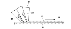
- FIG. 2 is a process explanatory view schematically showing a manufacturing process according to a preferred embodiment of the present invention.
- FIG. 3 is a process explanatory view schematically showing a manufacturing process according to another preferred embodiment of the present invention.
- FIG. 4 is a cross-sectional view of a sample schematically shown for explaining a method for measuring each parameter in the roughness curve.
- FIG. 5 is a graph for explaining the definition of each parameter in the roughness curve.
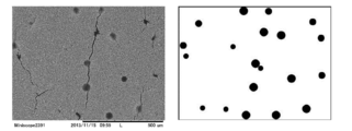
- FIG. 6 is a photomicrograph (left) and an image processed image (right) showing an example of pinhole measurement.
- the all-solid secondary battery of the present invention has specific irregularities at the interface between the inorganic solid electrolyte layer and the active material layer.
- preferred embodiments thereof will be described. First, an example of an all-solid secondary battery which is a preferred application mode thereof will be described.
- FIG. 1 is a cross-sectional view schematically showing an all solid state secondary battery (lithium ion secondary battery) according to a preferred embodiment of the present invention.
- the all-solid-state secondary battery 10 of the present embodiment includes a negative electrode current collector 1, a negative electrode active material layer 2, an inorganic solid electrolyte layer 3, a positive electrode active material layer 4, and a positive electrode current collector 5 in that order as viewed from the negative electrode side. Have in.
- Each layer is in contact with each other and has a laminated structure.
- the solid electrolyte composition is preferably used as a constituent material of the negative electrode active material layer, the positive electrode active material layer, and the inorganic solid electrolyte layer.
- the inorganic solid electrolyte layer, the positive electrode active material layer, and the negative electrode active material layer It is preferable to use as all constituent materials.
- the positive electrode active material layer and the negative electrode active material layer may be collectively referred to as an active material layer.
- the thicknesses of the positive electrode active material layer 4 and the negative electrode active material layer 3 can be determined according to the target battery capacity. In consideration of general element dimensions, it is preferably 1 ⁇ m or more, more preferably 1.5 ⁇ m or more, further preferably 3 ⁇ m or more, and particularly preferably 5 ⁇ m or more. As an upper limit, it is preferable that it is 1000 micrometers or less, It is more preferable that it is 600 micrometers or less, It is further more preferable that it is 400 micrometers or less, It is especially preferable that it is 200 micrometers or less.
- the inorganic solid electrolyte layer 3 is desirably as thin as possible while preventing a short circuit between the positive and negative electrodes.
- the effect of the present invention is remarkably exhibited.
- it is preferably 1 ⁇ m or more, more preferably 1.5 ⁇ m or more, further preferably 3 ⁇ m or more, and more preferably 5 ⁇ m or more.
- it is particularly preferred that As an upper limit, it is preferable that it is 1000 micrometers or less, It is more preferable that it is 600 micrometers or less, It is further more preferable that it is 400 micrometers or less, It is especially preferable that it is 200 micrometers or less.
- a laminate including a current collector, an active material layer, and a solid electrolyte layer is referred to as an “all-solid secondary battery”.
- the secondary battery electrode sheet may be housed in a casing (case) to be an all-solid secondary battery (for example, a coin battery, a laminate battery, or the like).
- the maximum height roughness Rz of at least one of the interface between the positive electrode active material layer and the inorganic solid electrolyte layer or the negative electrode active material layer and the inorganic solid electrolyte layer is 1.5 ⁇ m to 5 ⁇ m. This means that the interface between the two layers has irregularities with moderate roughness. That is, by setting the range of the maximum height roughness Rz to be equal to or more than the above lower limit value, the layer interface has a three-dimensional roughness, so that the active material can be activated even if a volume change occurs due to charge / discharge.
- the lower limit value of the maximum height roughness Rz is preferably 2 ⁇ m or more, and more preferably 2.3 ⁇ m or more.
- the upper limit is further preferably 4 ⁇ m or less, and particularly preferably 3 ⁇ m or less.
- the maximum height roughness Rz means Rz (maximum height roughness) in a roughness curve defined by JIS B0601-2013.
- the reference length in the present invention is 200 ⁇ m unless otherwise specified.
- the roughness curve of the layer interface and its Rz can be measured by observing a cross section perpendicular to the layer with an SEM as shown in FIG. In order to set the maximum height roughness Rz within a specific range, for example, a simultaneous multi-layer coating method or a wet-on-wet method described later can be employed.
- the manufacturing method is not limited to these.
- it is a powder laminated film or a dry cured film, after roughening the surface by pressing, it may be roughened by brushing or the like. Or it is good also as a setting which a predetermined unevenness
- the size of the solid electrolyte particles and the active material particles to be contained in the solid electrolyte layer and the active material layer is changed in consideration of the flow of particles during the drying process. And adjusting the amount of the particles, adjusting the wettability and viscosity of the composition (paste) forming the solid electrolyte layer and the active material layer, and the like.
- the density of the unevenness is not particularly limited, but it is preferably present relatively densely from the viewpoint of suitably exhibiting the effects of the present invention.
- the average length RSm of the roughness curve element it is preferably 0.01 ⁇ m or more, more preferably 0.03 ⁇ m or more, and particularly preferably 0.05 ⁇ m or more.
- the upper limit is preferably 90 ⁇ m or less, more preferably 60 ⁇ m or less, and particularly preferably 50 ⁇ m or less.
- the average length RSm of the roughness curve element can be measured by observing a cross section perpendicular to the layer with an SEM as shown in FIG. 4 unless otherwise specified.
- the reference length is set to 200 ⁇ m as in the measurement of the maximum roughness height.
- the number of pinholes is preferably regulated to 16 or less per 1 mm 2 .
- This pinhole usually occurs when a base layer is dried and solidified and has irregularities, and a paste is applied thereon and dried.
- the paste may not be placed there and may become pinholes.
- this pinhole can be suppressed or prevented by employing a multilayer coating or a wet-on-wet method.
- the pinhole is preferably not present because it may cause an electrically non-uniform state at this portion, or may cause a peeling start point or a short circuit.
- the number of pinholes is preferably 8 or less per 1 mm 2 , particularly preferably 4 or less, and particularly preferably 0.
- the positive electrode active material layer or the negative electrode active material layer is formed by applying a slurry, and the inorganic solid electrolyte layer is formed while the positive electrode active material layer or the negative electrode active material layer is in a wet state. Apply the slurry for.
- the wet state can be defined as a state where the solid content concentration is 75% by mass or less.
- the solid content concentration is preferably 70% by mass or less, more preferably 60% by mass or less, and particularly preferably 50% by mass or less.
- the nozzle (simultaneous multi-layer device) 20 shown in FIG. 2 is provided with a hole for supplying the lower layer coating liquid 2A and a hole for supplying the upper layer coating liquid 2B.
- This hole extends in the depth direction of the paper surface and forms a semi-cylindrical space.
- This one end is in a released state, and the coating liquid is applied in the direction of the support 21.
- This released portion also extends in the depth direction of the paper surface and forms a space in the form on the slit.
- the coating liquid supplied to each hole is supplied to the surface of the support (metal foil) 21 through the slit-shaped space.
- the lower layer coating solution 2 ⁇ / b> A slightly in front reaches the support 21 first to form the lower layer 22.
- the upper layer coating solution 2 ⁇ / b> B applied immediately thereafter is applied to the upper surface of the lower layer to form the upper layer 23.
- a three-layer structure in which the lower layer and the upper layer are provided on the support is realized.
- a support metal foil
- the lower layer is a positive electrode active material layer
- the middle layer is an inorganic solid electrolyte layer
- the upper layer is a negative electrode active material layer.
- the conveying speed of the support is preferably 2 to 500 m / min, more preferably 10 to 400 m / min, more preferably 30 to 360 m / min from the capability and accuracy of the conveying system of the coating machine. Is particularly preferred.
- the supply speed of the coating liquid is set by the coating width, the coating speed, the target film thickness after drying and the solid content of the coating liquid, but is preferably 1 to 10000 ml / min from the ability of the liquid feed pump and the like, and preferably 2 to 8000 ml / min. Is more preferably 3 to 6000 ml / min, particularly preferably 4 to 4000 ml / min.
- the liquid viscosity is preferably from 1 to 100,000 mPa ⁇ s, more preferably from 2 to 10,000 mPa ⁇ s, and even more preferably from 5 to 5000 mPa ⁇ s, from the viewpoint of the ability of the liquid feeding system, leveling properties after coating, and coating thickness after drying. 10 to 1000 mPa ⁇ s is particularly preferable. Further, when the viscosity of the coating solution forming each layer is greatly different, the roughness of the interface becomes large.
- the difference in the viscosity of the coating solution forming each layer is preferably 1000 mPa ⁇ s or less, more preferably 100 mPa ⁇ s or less, and 50 mPa ⁇ More preferably s or less, and particularly preferably 10 mPa ⁇ s or less.
- FIG. 3 shows an example in which three different nozzles 30A, 30B, and 30C are used.
- the apparatus is the same as the apparatus of FIG. 2, but the lower layer coating liquid 3 ⁇ / b> A is applied on the support 31, and this forms the lower layer 32.
- the intermediate layer coating solution 3B is applied at a slight interval, and this forms the intermediate layer 33.
- the upper layer coating liquid 3C is applied, and this forms the upper layer 34.
- a laminated structure having a lower positive electrode active material layer, a middle inorganic solid electrolyte layer, and an upper negative electrode active material layer is realized.
- each process condition such as the conveyance speed of the support and the supply speed of each coating liquid is the same as the conditions in the apparatus of FIG.
- the application interval of each coating liquid is not particularly limited as long as the wettability of the previously applied layer is maintained, Within 2 seconds is preferable, within 0.5 seconds is more preferable, and within 0.2 seconds is particularly preferable.
- An inorganic solid electrolyte is an inorganic solid electrolyte.
- the term “solid electrolyte” means a solid electrolyte capable of moving ions therein. From this viewpoint, the inorganic solid electrolyte may be referred to as an ion conductive inorganic solid electrolyte in consideration of the distinction from the electrolyte salt (supporting electrolyte) described later.
- the ionic conductivity of the inorganic solid electrolyte is not particularly limited, but is preferably 1 ⁇ 10 ⁇ 6 S / cm or more, more preferably 1 ⁇ 10 ⁇ 5 S / cm or more in lithium ions.
- inorganic solid electrolytes do not contain organic compounds such as polymer compounds and complex salts as electrolytes, they are clearly different from organic solid electrolytes (polymer electrolytes typified by PEO, organic electrolyte salts typified by LiTFSI, etc.). Differentiated.
- the inorganic solid electrolyte is a non-dissociable solid in a steady state, it does not dissociate or release into cations and anions even in the liquid.
- inorganic electrolyte salts LiPF 6 , LiBF 4 , LiFSI, LiCl, etc.
- the inorganic solid electrolyte has conductivity of metal ions (preferably lithium ions) belonging to Group 1 or Group 2 of the periodic table, but does not have electronic conductivity.
- the electrolyte layer or the active material layer contains a metal ion (preferably lithium ion) conductive inorganic solid electrolyte belonging to Group 1 or Group 2 of the Periodic Table.
- a metal ion preferably lithium ion
- the inorganic solid electrolyte a solid electrolyte material applied to this type of product can be appropriately selected and used.
- Typical examples of inorganic solid electrolytes include (i) sulfide-based inorganic solid electrolytes and (ii) oxide-based inorganic solid electrolytes.
- the sulfide-based inorganic solid electrolyte contains sulfur (S) and has ion conductivity of a metal belonging to Group 1 or Group 2 of the periodic table, and What has electronic insulation is preferable.
- S sulfur
- a lithium ion conductive inorganic solid electrolyte that satisfies the composition represented by the following formula (1) can be given.
- Li a Mb P c S d (1) In the formula, M represents an element selected from B, Zn, Si, Cu, Ga, and Ge. Ad represents the composition ratio of each element, and a: b: c: d represents 1 to 12, respectively. : 0 to 1: 1: 2 to 9 are satisfied.
- the composition ratio of each element can be controlled by adjusting the blending amount of the raw material compound when producing the sulfide-based inorganic solid electrolyte as described below.
- the sulfide-based inorganic solid electrolyte may be amorphous (glass) or crystallized (glass ceramic), or only part of it may be crystallized.
- the ratio of Li 2 S to P 2 S 5 in the Li—PS system glass and the Li—PS system glass ceramic is a molar ratio of Li 2 S: P 2 S 5 , preferably 65:35 to 85:15, more preferably 68:32 to 75:25.
- the lithium ion conductivity can be increased.
- the lithium ion conductivity can be preferably 1 ⁇ 10 ⁇ 4 S / cm or more, more preferably 1 ⁇ 10 ⁇ 3 S / cm or more.
- the compound include those using a raw material composition containing, for example, Li 2 S and a sulfide of an element belonging to Group 13 to Group 15.
- Li 2 S—P 2 S 5 Li 2 S—GeS 2 , Li 2 S—GeS 2 —ZnS, Li 2 S—Ga 2 S 3 , Li 2 S—GeS 2 —Ga 2 S 3 Li 2 S—GeS 2 —P 2 S 5 , Li 2 S—GeS 2 —Sb 2 S 5 , Li 2 S—GeS 2 —Al 2 S 3 , Li 2 S—SiS 2 , Li 2 S—Al 2 S 3 , Li 2 S—SiS 2 —Al 2 S 3 , Li 2 S—SiS 2 —P 2 S 5 , Li 2 S—SiS 2 —LiI, Li 2 S—SiS 2 —Li 4 SiO 4 , Li 2 Examples thereof include S—SiS 2 —Li 3
- Li 2 S—P 2 S 5 , Li 2 S—GeS 2 —Ga 2 S 3 , Li 2 SGeS 2 —P 2 S 5 , Li 2 S—SiS 2 —P 2 S 5 , Li 2 S— A crystalline and / or amorphous raw material composition made of SiS 2 —Li 4 SiO 4 or Li 2 S—SiS 2 —Li 3 PO 4 is preferable because it has high lithium ion conductivity.
- Examples of a method for synthesizing a sulfide solid electrolyte material using such a raw material composition include an amorphization method.
- the amorphization method include a mechanical milling method and a melt quenching method, and among them, the mechanical milling method is preferable. This is because processing at room temperature is possible, and the manufacturing process can be simplified.
- the sulfide-based inorganic solid electrolyte is, for example, T.M. Ohtomo, A .; Hayashi, M .; Tatsumisago, Y. et al. Tsuchida, S .; Hama, K .; Kawamoto, Journal of Power Sources, 233, (2013), pp231-235 and A.K. Hayashi, S .; Hama, H .; Morimoto, M .; Tatsumisago, T .; Minami, Chem. Lett. , (2001), pp 872-873, and the like.
- Oxide-based inorganic solid electrolyte contains oxygen (O), has an ionic conductivity of a metal belonging to Group 1 or Group 2 of the periodic table, and is an electron What has insulation is preferable.
- LISICON Lithium super ionic conductor
- LiTi 2 P 3 O 12 Al Li 1+ having a NASICON (Natium super ionic conductor) type crystal structure
- Li, P and O are also desirable.
- lithium phosphate Li 3 PO 4
- LiPON obtained by substituting part of oxygen of lithium phosphate with nitrogen
- LiPOD LiPOD
- LiPOD LiPOD
- Mo Mo
- Ru Ag
- Ta W
- Pt Au
- AON A is at least one selected from Si, B, Ge, Al, C, Ga, etc.
- Li 1 + x + y (Al, Ga) x (Ti, Ge) 2 -xSi y P 3 -yO 12 (where 0 ⁇ x ⁇ 1, 0 ⁇ y ⁇ 1) has high lithium ion conductivity. It is preferable because it is chemically stable and easy to handle. These may be used alone or in combination of two or more.
- the ionic conductivity of the lithium ion conductive oxide-based inorganic solid electrolyte is preferably 1 ⁇ 10 ⁇ 6 S / cm or more, more preferably 1 ⁇ 10 ⁇ 5 S / cm or more.
- X 10 ⁇ 5 S / cm or more is particularly preferable.
- an oxide-based inorganic solid electrolyte Since the oxide-based inorganic solid electrolyte generally has a higher hardness, the interface resistance is likely to increase in the all-solid secondary battery. By applying the present invention, the effect becomes more prominent.
- the oxide-based inorganic solid electrolyte is hard and tends to be inferior in moldability, and the roughness of the interface between the active material layer and the inorganic solid electrolyte layer after coating tends to remain after molding. Therefore, it is effective to apply the present invention or a preferred embodiment thereof whose production is controlled at the application stage.
- the said inorganic solid electrolyte may be used individually by 1 type, or may be used in combination of 2 or more type.
- the average particle size of the inorganic solid electrolyte is not particularly limited, but is preferably selected in consideration of the influence on the interface roughness of the active material layer / inorganic solid electrolyte layer. Specifically, it is preferably 0.01 ⁇ m or more, more preferably 0.1 ⁇ m or more, further preferably 0.5 ⁇ m or more, and particularly preferably 1 ⁇ m or more. As an upper limit, it is preferable that it is 100 micrometers or less, It is more preferable that it is 50 micrometers or less, It is further more preferable that it is 10 micrometers or less, It is especially preferable that it is 5 micrometers or less. Unless otherwise specified, the average particle size of the inorganic solid electrolyte is determined according to the conditions measured in Examples described later.
- the concentration of the inorganic solid electrolyte in the solid electrolyte composition is preferably 50% by mass or more and 100% by mass in 100% by mass of the solid component when considering both the battery performance and the reduction / maintenance effect of the interface resistance. % Or more is more preferable, and 90% by mass or more is particularly preferable. As an upper limit, it is preferable that it is 99.9 mass% or less from the same viewpoint, It is more preferable that it is 99.5 mass% or less, It is especially preferable that it is 99 mass% or less. However, when used together with a positive electrode active material or a negative electrode active material to be described later, the sum is preferably in the above concentration range.
- a binder can be used in the solid electrolyte composition of the present invention. Thereby, the above-described inorganic solid electrolyte particles can be bound to realize better ion conductivity.
- the type of the binder is not particularly limited, but a styrene-acrylic copolymer (see, for example, JP-A-2013-008611 and International Publication No. 2011-105574 pamphlet), and a hydrogenated butadiene copolymer (see, for example, JP-A-11-11). No. 086899, pamphlet of International Publication No.
- polyolefin polymers such as polyethylene, polypropylene, polytetrafluoroethylene (for example, see JP 2012-99315 A), compounds having polyoxyethylene chains ( JP-A-2013-008611), norbornene-based polymer (JP-A-2011-233422) and the like can be used.
- the polymer compound constituting the binder preferably has a weight average molecular weight of 5,000 or more, more preferably 10,000 or more, and particularly preferably 30,000 or more. As an upper limit, it is preferable that it is 1,000,000 or less, and it is more preferable that it is 400,000 or less.
- the molecular weight measurement method is based on the conditions measured in the examples described below unless otherwise specified.
- the glass transition temperature (Tg) of the binder polymer is preferably 100 ° C. or less from the viewpoint of improving the binding property, more preferably 30 ° C. or less, and particularly preferably 0 ° C. or less.
- the lower limit is preferably ⁇ 100 ° C. or higher, more preferably ⁇ 80 ° C. or higher, from the viewpoint of manufacturing suitability and performance stability.
- the binder polymer may be crystalline or amorphous. In the case of crystallinity, the melting point is preferably 200 ° C. or lower, more preferably 190 ° C. or lower, and particularly preferably 180 ° C. or lower. Although there is no lower limit in particular, 120 degreeC or more is preferable and 140 degreeC or more is more preferable.
- the measurement from the created all-solid-state secondary battery is, for example, disassembling the battery, placing the electrode in water and dispersing the material, filtering, collecting the remaining solid, and measuring Tg described later
- the glass transition temperature can be measured by the method.
- the average particle size of the binder polymer particles is preferably 0.01 ⁇ m or more, more preferably 0.05 ⁇ m or more, and particularly preferably 0.1 ⁇ m or more.
- As an upper limit it is preferable that it is 500 micrometers or less, It is more preferable that it is 100 micrometers or less, It is especially preferable that it is 10 micrometers or less.
- the standard deviation of the particle size distribution is preferably 0.05 or more, more preferably 0.1 or more, and particularly preferably 0.15 or more.
- the upper limit is preferably 1 or less, more preferably 0.8 or less, and particularly preferably 0.6 or less.
- the average particle diameter and the degree of particle dispersion of the polymer particles are based on the conditions (dynamic light scattering method) employed in Examples described below unless otherwise specified.
- the binder polymer particles preferably have a smaller particle size than the average particle size of the inorganic solid electrolyte particles.
- the size of the polymer particles in the above range, it is possible to realize good adhesion and suppression of interfacial resistance in combination with the inorganic solid electrolyte particles having a predetermined particle size distribution.
- the measurement from the prepared all-solid-state secondary battery for example, after disassembling the battery and peeling off the electrode, the electrode material is measured according to the method for measuring the particle size of the polymer described later, and measured in advance. This can be done by eliminating the measured value of the particle size of the particles other than the polymer.
- the blending amount of the binder is preferably 0.1 parts by mass or more, and 0.3 parts by mass or more with respect to 100 parts by mass of the inorganic solid electrolyte (including this when an active material is used). More preferred is 1 part by mass or more. As an upper limit, it is preferable that it is 50 mass parts or less, It is more preferable that it is 20 mass parts or less, It is especially preferable that it is 10 mass parts or less.
- the binder in the solid content, is preferably 0.1% by mass or more, more preferably 0.3% by mass or more, and particularly preferably 1% by mass or more. preferable.
- ⁇ Binders may be used alone or in combination of a plurality of types. Further, it may be used in combination with other particles.
- the binder particles may be composed of only a specific polymer constituting the binder particles, or may be composed in a form containing another kind of material (polymer, low molecular compound, inorganic compound, etc.).
- the solid electrolyte composition may contain a lithium salt.
- a lithium salt usually used in this type of product is preferable, and there is no particular limitation, but for example, the following are preferable.
- Inorganic lithium salts inorganic fluoride salts such as LiPF 6 , LiBF 4 , LiAsF 6 , LiSbF 6 ; perhalogenates such as LiClO 4 , LiBrO 4 , LiIO 4 ; inorganic chloride salts such as LiAlCl 4 etc.
- (L-3) Oxalatoborate salt lithium bis (oxalato) borate, lithium difluorooxalatoborate and the like.
- Rf 1 and Rf 2 each represent a perfluoroalkyl group.
- the content of the lithium salt is preferably 0.1 parts by mass or more and more preferably 0.5 parts by mass or more with respect to 100 parts by mass of the inorganic solid electrolyte.
- As an upper limit it is preferable that it is 10 mass parts or less, and it is more preferable that it is 5 mass parts or less.
- the electrolyte used for electrolyte solution may be used individually by 1 type, or may combine 2 or more types arbitrarily.
- a dispersion medium in which the above components are dispersed may be used.
- a dispersion medium When producing an all-solid secondary battery, it is preferable to add a dispersion medium to the solid electrolyte composition to make a paste from the viewpoint of uniformly coating the solid electrolyte composition to form a film.
- the dispersion medium When forming the solid electrolyte layer of the all-solid secondary battery, the dispersion medium is removed by drying.
- the dispersion medium include a water-soluble organic solvent. Specific examples include the following.
- Alcohol compound solvent Methyl alcohol, ethyl alcohol, 1-propyl alcohol, 2-propyl alcohol, 2-butanol, ethylene glycol, propylene glycol, glycerin, 1,6-hexanediol, cyclohexanediol, sorbitol, xylitol, 2-methyl- 2,4-pentanediol, 1,3-butanediol, 1,4-butanediol, etc.
- Ether compound solvents (including hydroxyl group-containing ether compounds) Dimethyl ether, diethyl ether, diisopropyl ether, dibutyl ether, t-butyl methyl ether, cyclohexyl methyl ether, anisole, tetrahydrofuran, alkylene glycol alkyl ether (ethylene glycol monomethyl ether, ethylene glycol monobutyl ether, diethylene glycol, dipropylene glycol, propylene glycol monomethyl ether , Diethylene glycol monomethyl ether, triethylene glycol, polyethylene glycol, propylene glycol monomethyl ether, dipropylene glycol monomethyl ether, tripropylene glycol monomethyl ether, diethylene glycol monobutyl ether, diethylene glycol monobutyl ether, etc.) Amide compound solvents N, N-dimethylformamide, 1-methyl-2-pyrrolidone, 2-pyrrolidinone, 1,3-dimethyl-2-imidazolid
- Ketone compound solvents Acetone, methyl ethyl ketone, methyl isobutyl ketone, cyclohexanone, etc.
- Aromatic compound solvents benzene, toluene, etc.
- Nitrile compound solvent Acetonitrile, isobutyronitrile
- the dispersion medium preferably has a boiling point at normal pressure (1 atm) of 80 ° C. or higher, more preferably 90 ° C. or higher.
- the upper limit is preferably 220 ° C. or lower, and more preferably 180 ° C. or lower.
- the solubility of the binder in the dispersion medium is preferably 20% by mass or less, more preferably 10% by mass or less, and particularly preferably 3% by mass or less at 20 ° C.
- the lower limit is practically 0.01% by mass or more.
- the said dispersion medium may be used individually by 1 type, or may be used in combination of 2 or more type.
- the viscosity of the solid electrolyte composition is adjusted in relation to simultaneous multilayer coating or a wet-on-wet manufacturing method.
- the viscosity of the composition is preferably 1 mPa ⁇ s or more, more preferably 2 mPa ⁇ s or more, and particularly preferably 5 mPa ⁇ s or more.
- the upper limit is preferably 100,000 mPa ⁇ s or less, more preferably 10,000 mPa ⁇ s or less, and particularly preferably 5000 mPa ⁇ s or less.
- the viscosity measurement method is based on the conditions measured in the examples described later.
- the quantity of the dispersion medium in a solid electrolyte composition can be made into arbitrary quantity with the balance of the viscosity of a solid electrolyte composition, and a dry load. Generally, it is preferably 20 to 99% by mass in the solid electrolyte composition.
- the solid electrolyte composition of the present invention may be prepared by a conventional method, and examples thereof include a method of treating the inorganic solid electrolyte particles by a wet dispersion method or a dry dispersion method.
- a wet dispersion method include a ball mill, a bead mill, and a sand mill.
- examples of the dry dispersion method include a ball mill, a bead mill, and a sand mill. After this dispersion, particles and aggregates other than the predetermined particle diameter can be removed by appropriately performing filtration.
- various dispersion media such as various dispersion balls and dispersion beads can be used.
- zirconia beads, titania beads, alumina beads, and steel beads, which are high specific gravity dispersion media, are suitable.
- the solid electrolyte composition of the present invention may contain a positive electrode active material. Thereby, it can be set as the composition for positive electrode materials. It is preferable to use a transition metal oxide for the positive electrode active material, and it is preferable to have a transition element M a (one or more elements selected from Co, Ni, Fe, Mn, Cu, and V). Further, mixed element M b (elements of the first (Ia) group of the metal periodic table other than lithium, elements of the second (IIa) group, Al, Ga, In, Ge, Sn, Pb, Sb, Bi, Si , P, B, etc.) may be mixed.
- transition metal oxide examples include specific transition metal oxides including those represented by any of the following formulas (MA) to (MC), or other transition metal oxides such as V 2 O 5 and MnO 2. Is mentioned.
- the positive electrode active material a particulate positive electrode active material may be used. Specifically, a transition metal oxide capable of reversibly inserting and releasing lithium ions can be used, but the specific transition metal oxide is preferably used.
- the transition metal oxides, oxides containing the above transition element M a is preferably exemplified.
- a mixed element M b (preferably Al) or the like may be mixed.
- the mixing amount is preferably 0 to 30 mol% with respect to the amount of the transition metal. That the molar ratio of li / M a was synthesized were mixed so that 0.3 to 2.2, more preferably.
- M 1 is as defined above Ma.
- a represents 0 to 1.2 (preferably 0.2 to 1.2), and preferably 0.6 to 1.1.
- b represents 1 to 3 and is preferably 2.
- a part of M 1 may be substituted with the mixed element M b .
- the transition metal oxide represented by the above formula (MA) typically has a layered rock salt structure.
- the transition metal oxide is more preferably one represented by the following formulas.
- g has the same meaning as a.
- j represents 0.1 to 0.9.
- i represents 0 to 1; However, 1-ji is 0 or more.
- k has the same meaning as b above.
- Specific examples of the transition metal compound include LiCoO 2 (lithium cobaltate [LCO]), LiNi 2 O 2 (lithium nickelate) LiNi 0.85 Co 0.01 Al 0.05 O 2 (nickel cobalt aluminum acid Lithium [NCA]), LiNi 0.33 Co 0.33 Mn 0.33 O 2 (lithium nickel manganese cobaltate [NMC]), LiNi 0.5 Mn 0.5 O 2 (lithium manganese nickelate).
- the transition metal oxide represented by the formula (MA) partially overlaps, but when represented by changing the notation, those represented by the following are also preferable examples.
- (I) Li g Ni x Mn y Co z O 2 (x> 0.2, y> 0.2, z ⁇ 0, x + y + z 1) Representative: Li g Ni 1/3 Mn 1/3 Co 1/3 O 2 Li g Ni 1/2 Mn 1/2 O 2
- (Ii) Li g Ni x Co y Al z O 2 (x> 0.7, y>0.1,0.1> z ⁇ 0.05, x + y + z 1) Representative: Li g Ni 0.8 Co 0.15 Al 0.05 O 2
- M 2 is as defined above Ma.
- c represents 0 to 2 (preferably 0.2 to 2), and preferably 0.6 to 1.5.
- d represents 3 to 5 and is preferably 4.
- the transition metal oxide represented by the formula (MB) is more preferably one represented by the following formulas.
- (MB-1) Li m Mn 2 O n
- (MB-2) Li m Mn p Al 2-p O n
- (MB-3) Li m Mn p Ni 2-p O n
- m is synonymous with c.
- n is synonymous with d.
- p represents 0-2.
- Specific examples of the transition metal compound are LiMn 2 O 4 and LiMn 1.5 Ni 0.5 O 4 .
- Preferred examples of the transition metal oxide represented by the formula (MB) include those represented by the following.
- an electrode containing Ni is more preferable from the viewpoint of high capacity and high output.
- Transition metal oxide represented by formula (MC) As the lithium-containing transition metal oxide, it is also preferable to use a lithium-containing transition metal phosphor oxide, and among them, one represented by the following formula (MC) is also preferable. Li e M 3 (PO 4 ) f ... (MC)
- e represents 0 to 2 (preferably 0.2 to 2), and is preferably 0.5 to 1.5.
- f represents 1 to 5, and preferably 0.5 to 2.
- the M 3 represents one or more elements selected from V, Ti, Cr, Mn, Fe, Co, Ni, and Cu.
- the M 3 are, in addition to the mixing element M b above, Ti, Cr, Zn, Zr, may be substituted by other metals such as Nb.
- Specific examples include, for example, olivine-type iron phosphates such as LiFePO 4 and Li 3 Fe 2 (PO 4 ) 3 , iron pyrophosphates such as LiFeP 2 O 7 , cobalt phosphates such as LiCoPO 4 , and Li 3.
- Monoclinic Nasicon type vanadium phosphate salts such as V 2 (PO 4 ) 3 (lithium vanadium phosphate) can be mentioned.
- the a, c, g, m, and e values representing the composition of Li are values that change due to charge and discharge, and are typically evaluated as values in a stable state when Li is contained.
- the composition of Li is shown as a specific value, but this also varies depending on the operation of the battery.
- the average particle size of the positive electrode active material is preferably 0.01 ⁇ m or more, more preferably 0.1 ⁇ m or more, even more preferably 0.5 ⁇ m or more in consideration of the influence on the interface roughness of the active material layer / inorganic solid electrolyte layer. 1 ⁇ m or more is particularly preferable. As an upper limit, 100 micrometers or less are preferable, 50 or less are more preferable, 10 or less are more preferable, and 5 micrometers or less are especially preferable. In order to make the positive electrode active material have a predetermined particle size, an ordinary pulverizer or classifier may be used.
- the positive electrode active material obtained by the firing method may be used after being washed with water, an acidic aqueous solution, an alkaline aqueous solution, or an organic solvent.
- the concentration of the positive electrode active material is not particularly limited, but is preferably 20 to 90% by mass, and more preferably 40 to 80% by mass in 100% by mass of the solid component in the solid electrolyte composition.
- the positive electrode active materials may be used alone or in combination of two or more.
- the solid electrolyte composition of the present invention may contain a negative electrode active material. Thereby, it can be set as the composition for negative electrode materials.
- the negative electrode active material those capable of reversibly inserting and releasing lithium ions are preferable.
- the material is not particularly limited, and is a carbonaceous material, a metal oxide such as tin oxide or silicon oxide, a metal composite oxide, a lithium alloy such as lithium alone or a lithium aluminum alloy, and an alloy with lithium such as Sn or Si. Examples thereof include metals that can be formed. Of these, carbonaceous materials or lithium composite oxides are preferably used from the viewpoint of reliability.
- the metal composite oxide is preferably capable of inserting and extracting lithium.
- the material is not particularly limited, but preferably contains titanium and / or lithium as a constituent component from the viewpoint of high current density charge / discharge characteristics.
- the carbonaceous material used as the negative electrode active material is a material substantially made of carbon.
- Examples thereof include carbonaceous materials obtained by baking various synthetic resins such as artificial pitches such as petroleum pitch, natural graphite, and vapor-grown graphite, and PAN-based resins and furfuryl alcohol resins.
- various carbon fibers such as PAN-based carbon fiber, cellulose-based carbon fiber, pitch-based carbon fiber, vapor-grown carbon fiber, dehydrated PVA-based carbon fiber, lignin carbon fiber, glassy carbon fiber, activated carbon fiber, mesophase micro
- Examples thereof include spheres, graphite whiskers, and flat graphite.
- carbonaceous materials can be divided into non-graphitizable carbon materials and graphite-based carbon materials depending on the degree of graphitization.
- the carbonaceous material preferably has a face spacing, density, and crystallite size described in JP-A-62-222066, JP-A-2-6856, and 3-45473.
- the carbonaceous material does not have to be a single material, and a mixture of natural graphite and artificial graphite described in JP-A-5-90844, graphite having a coating layer described in JP-A-6-4516, or the like is used. You can also.
- an amorphous oxide is particularly preferable, and chalcogenite, which is a reaction product of a metal element and an element of Group 16 of the periodic table, is also preferably used. It is done.
- amorphous as used herein means an X-ray diffraction method using CuK ⁇ rays, which has a broad scattering band having a peak in the region of 20 ° to 40 ° in terms of 2 ⁇ , and is a crystalline diffraction line. You may have.
- the strongest intensity of crystalline diffraction lines seen from 2 ° to 40 ° to 70 ° is 100 times the diffraction line intensity at the peak of the broad scattering band seen from 2 ° to 20 °. It is preferable that it is 5 times or less, and it is particularly preferable not to have a crystalline diffraction line.
- amorphous metal oxides and chalcogenides are more preferable, and elements in groups 13 (IIIB) to 15 (VB) of the periodic table are preferable.
- oxides and chalcogenides composed of one kind of Al, Ga, Si, Sn, Ge, Pb, Sb, Bi or a combination of two or more kinds thereof.
- preferable amorphous oxides and chalcogenides include, for example, Ga 2 O 3 , SiO, GeO, SnO, SnO 2 , PbO, PbO 2 , Pb 2 O 3 , Pb 2 O 4 , Pb 3 O 4 , Sb 2 O 3 , Sb 2 O 4 , Sb 2 O 5 , Bi 2 O 3 , Bi 2 O 4 , SnSiO 3 , GeS, SnS, SnS 2 , PbS, PbS 2 , Sb 2 S 3 , Sb 2 S 5 , such as SnSiS 3 may preferably be mentioned. Moreover, these may be a complex oxide with lithium oxide, for example, Li 2 SnO 2 .
- the average particle size of the negative electrode active material is preferably 0.01 ⁇ m or more, more preferably 0.1 ⁇ m or more, even more preferably 0.5 ⁇ m or more in consideration of the influence on the interface roughness of the active material layer / inorganic solid electrolyte layer. 1 ⁇ m or more is particularly preferable. As an upper limit, 100 micrometers or less are preferable, 50 or less are more preferable, 10 or less are more preferable, and 5 micrometers or less are especially preferable. To obtain a predetermined particle size, a well-known pulverizer or classifier is used.
- a mortar, a ball mill, a sand mill, a vibrating ball mill, a satellite ball mill, a planetary ball mill, a swirling air flow type jet mill or a sieve is preferably used.
- wet pulverization in the presence of water or an organic solvent such as methanol can be performed as necessary.
- classification is preferably performed.
- the classification method is not particularly limited, and a sieve, an air classifier, or the like can be used as necessary. Classification can be used both dry and wet.
- the chemical formula of the compound obtained by the above firing method can be calculated from an inductively coupled plasma (ICP) emission spectroscopic analysis method as a measurement method, and from a mass difference between powders before and after firing as a simple method.
- ICP inductively coupled plasma
- Examples of the negative electrode active material that can be used in combination with the amorphous oxide negative electrode active material centering on Sn, Si, and Ge include carbon materials that can occlude and release lithium ions or lithium metal, lithium, lithium alloys, lithium A metal that can be alloyed with is preferable.
- a negative electrode active material containing Si element In the all solid state secondary battery of the present invention, it is also preferable to apply a negative electrode active material containing Si element.
- a Si negative electrode can occlude more Li ions than current carbon negative electrodes (graphite, acetylene black, etc.). That is, since the amount of Li ion storage per weight increases, the battery capacity can be increased. As a result, there is an advantage that the battery driving time can be extended, and use in a battery for vehicles is expected in the future.
- the volume change associated with insertion and extraction of Li ions is large. In one example, the volume expansion of the carbon negative electrode is about 1.2 to 1.5 times, and the volume of Si negative electrode is about three times. There is also an example.
- the durability of the electrode layer is insufficient, and for example, contact shortage is likely to occur, and cycle life (battery life) is shortened.
- the solid electrolyte composition of the present invention even in an electrode layer in which such expansion / contraction increases, the high durability (strength) can be exhibited and the excellent advantages can be exhibited more effectively. .
- the concentration of the negative electrode active material is not particularly limited, but is preferably 10 to 80% by mass, more preferably 20 to 70% by mass in 100% by mass of the solid component in the solid electrolyte composition.
- the solid electrolyte composition according to the present invention contains a positive electrode active material or a negative electrode active material
- a paste containing a positive electrode active material or a negative electrode active material may be prepared as a composition that does not contain inorganic solid electrolyte particles.
- you may make the active material layer of a positive electrode and a negative electrode contain a conductive support agent suitably as needed.
- carbon fibers such as graphite, carbon black, acetylene black, ketjen black, carbon nanotubes, metal powders, metal fibers, polyphenylene derivatives, and the like can be included.
- the said negative electrode active material may be used individually by 1 type, or may be used in combination of 2 or more type.
- the positive / negative current collector an electron conductor that does not cause a chemical change is preferably used.
- the current collector of the positive electrode in addition to aluminum, stainless steel, nickel, titanium, etc., the surface of aluminum or stainless steel is preferably treated with carbon, nickel, titanium, or silver. Among them, aluminum and aluminum alloys are preferable. More preferred.
- the negative electrode current collector aluminum, copper, stainless steel, nickel, and titanium are preferable, and aluminum, copper, and a copper alloy are more preferable.
- a film sheet is usually used, but a net, a punched one, a lath body, a porous body, a foamed body, a molded body of a fiber group, and the like can also be used.
- the thickness of the current collector is not particularly limited, but is preferably 1 ⁇ m to 500 ⁇ m.
- the current collector surface is roughened by surface treatment.
- the all-solid-state secondary battery may be manufactured by a conventional method.
- the coating method for each of the above compositions is preferably the simultaneous multi-layer coating method or the wet-on-wet method described above.
- a heat treatment is performed after each application of the composition forming the positive electrode active material layer (paste), the composition forming the inorganic solid electrolyte layer (paste), and the composition forming the negative electrode active material layer (paste). It is preferable.
- heating temperature is not specifically limited, 30 degreeC or more is preferable and 60 degreeC or more is more preferable.
- the upper limit is preferably 300 ° C. or lower, and more preferably 250 ° C. or lower.
- the all solid state secondary battery according to the present invention can be applied to various uses.
- the application mode is not particularly limited, for example, when installed in an electronic device, a notebook computer, a pen input personal computer, a mobile personal computer, an electronic book player, a cellular phone, a cordless phone, a pager, a handy terminal, a portable fax machine, a portable copy.
- Examples include portable printers, headphone stereos, video movies, LCD TVs, handy cleaners, portable CDs, minidiscs, electric shavers, transceivers, electronic notebooks, calculators, memory cards, portable tape recorders, radios, backup power supplies, and memory cards.
- Other consumer products include automobiles, electric vehicles, motors, lighting equipment, toys, game equipment, road conditioners, watches, strobes, cameras, medical equipment (such as pacemakers, hearing aids, and shoulder grinders). Furthermore, it can be used for various military use and space use. Moreover, it can also combine with a solar cell.
- An all-solid secondary battery refers to a secondary battery in which the positive electrode, the negative electrode, and the electrolyte are all solid. In other words, it is distinguished from an electrolyte type secondary battery using a carbonate-based solvent as an electrolyte.
- this invention presupposes an inorganic all-solid-state secondary battery.
- the all-solid-state secondary battery is classified into a polymer all-solid-state secondary battery that uses a polymer compound such as polyethylene oxide as an electrolyte and an inorganic all-solid-state secondary battery that uses the above Li-PS, LLT, or LLZ. Is done.
- the application of the polymer compound to the inorganic all-solid secondary battery is not hindered, and the polymer compound can be applied as a binder for the positive electrode active material, the negative electrode active material, and the inorganic solid electrolyte particles.
- the inorganic solid electrolyte is distinguished from an electrolyte (polymer electrolyte) using the above-described polymer compound as an ion conductive medium, and the inorganic compound serves as an ion conductive medium. Specific examples include Li—PS, LLT, and LLZ.
- the inorganic solid electrolyte itself does not release cations (Li ions) but exhibits an ion transport function.
- a material that is added to the electrolytic solution or the solid electrolyte layer and serves as a source of ions that release cations is sometimes called an electrolyte, but it is distinguished from the electrolyte as the ion transport material.
- electrolyte salt or “supporting electrolyte”.
- the electrolyte salt include LiTFSI (lithium bistrifluoromethanesulfonimide).
- the term “composition” means a mixture in which two or more components are uniformly mixed. However, as long as the uniformity is substantially maintained, aggregation or uneven distribution may partially occur within a range in which a desired effect is achieved.
- the solid electrolyte composition basically refers to a composition (typically a paste) that is a material for forming the electrolyte layer, and the electrolyte layer formed by curing the composition includes It shall not be included.
- Lithium sulfide Li 2 S, manufactured by Aldrich, purity> 99.98%) in a glove box under an argon atmosphere (dew point of ⁇ 70 ° C.) 2.42 g and diphosphorus pentasulfide (P 2 S 5 , Aldrich, purity> 99%) 3.90 g were weighed, put into an agate mortar, and mixed for 5 minutes using an agate pestle.
- Li 2 S and P 2 S 5 at a molar ratio of Li 2 S: P 2 S 5 75: was 25.
- 66 zirconia beads having a diameter of 5 mm were introduced into a 45 mL container (manufactured by Fritsch) made of zirconia, the whole mixture of lithium sulfide and diphosphorus pentasulfide was introduced, and the container was completely sealed under an argon atmosphere.
- a container is set on a planetary ball mill P-7 manufactured by Frichtu, and mechanical milling is performed at a temperature of 25 ° C. and a rotation speed of 510 rpm for 20 hours to obtain 6.20 g of a yellow powder sulfide solid electrolyte material (Li / P / S glass). Obtained.
- the average particle size of the inorganic solid electrolyte particles was as shown in the table.
- the viscosity was 540 mPa ⁇ s (25 ° C.).
- the HSBR had a weight molecular weight of 200,000 and a Tg of ⁇ 50 ° C.
- Solid electrolyte composition S-2 was prepared in the same manner as solid electrolyte composition S-1.
- the solid electrolyte compositions S-1 and S-2 used for the solid electrolyte layer are indicated as LLT (S-1) and LLT (S-2), respectively.
- the average particle diameter of the sulfide solid electrolyte particles was as shown in the table.
- the viscosity was 600 mPa ⁇ s (25 ° C.).
- composition for secondary battery negative electrode Planetary mixer (TK Hibismix, manufactured by PRIMIX), 100 parts of graphite (Nippon Graphite Industries spheroidized graphite powder), 5 parts of acetylene black, solid electrolyte obtained above Composition S-1 (75 parts) and N-methylpyrrolidone (270 parts) were added, and the mixture was stirred at 40 rpm for 1 hour.
- the viscosity was 110 mPa ⁇ s (25 ° C.).
- the solid electrolyte composition obtained above was applied with an applicator having an arbitrary clearance, and 80 ° C. for 1 hour and further 110 ° C. Heated for 1 hour. Thereafter, the composition for a secondary battery negative electrode obtained above was further applied and heated at 80 ° C. for 1 hour and further at 110 ° C. for 1 hour.
- a stainless steel (SUS316L) foil having a thickness of 20 ⁇ m was combined on the negative electrode layer, and heated and pressurized to an arbitrary density using a heat press machine to obtain an electrode sheet for a secondary battery.
- the average particle size of the inorganic solid electrolyte particles was as shown in the table.
- Preparation Example of Secondary Battery Positive Electrode Composition A planetary mixer (TK Hibismix, manufactured by PRIMIX) was charged with 100 parts of lithium cobaltate, 5 parts of acetylene black, and 75 parts of the solid electrolyte composition S-2 obtained above. In addition, stirring was performed at 40 rpm for 1 hour.
- the positive electrode composition powder for the secondary battery together with the positive electrode current collector is heated and pressurized to a desired density using a heat press machine to form a positive electrode composition powder molding layer on the surface of the positive electrode current collector did.
- the solid electrolyte composition powder obtained above was placed on the positive electrode composition powder molding layer so as to have an arbitrary thickness.
- the positive electrode current collector and the positive electrode composition powder molding layer together with the solid electrolyte composition powder are heated and pressurized to a desired density using a heat press machine, and the solid electrolyte is applied to the surface of the positive electrode composition powder molding layer.
- a composition powder molding layer was formed.
- the negative electrode composition powder was placed on the solid electrolyte composition powder molding layer so as to have an arbitrary thickness.
- a SUS316L foil having a thickness of 20 ⁇ m as a negative electrode current collector was laminated on the surface. And it heated and pressurized so that it might become arbitrary density using a heat press machine, and the electrode sheet for secondary batteries was obtained.
- the temperature of the nozzle of the supply unit was room temperature (about 25 ° C.).
- the positive electrode composition and the negative electrode composition when the solid electrolyte composition was laminated were sampled, and the solid content concentration was measured. As a result, in all cases, the solid content was about 40% by mass (the wet state was maintained). Then, it heated at 80 degreeC for 1 hour and further 110 degreeC for 1 hour, laminated
- the thickness of the cured film (inorganic solid electrolyte layer) of a solid electrolyte composition made a difference by adjusting the supply amount of the raw material composition.
- the measurement method of each parameter is as follows. ⁇ Surface roughness measurement method> The cross section of the laminate composed of the positive electrode layer / inorganic solid electrolyte layer / negative electrode layer is photographed at 1000 times using SEM. The cross section was cut with a diamond knife manufactured by DiATOME, and a portion suitable for observation was selected. The average value was employ
- ⁇ Pinhole measurement method> For example, after applying and drying the positive electrode layer forming slurry on the current collector and then applying and drying the inorganic solid electrolyte layer forming slurry, the surface of the dried inorganic solid electrolyte layer is 200 times using SEM (Hitachi). Take a picture with High Technologies TM-1000). The target area to be measured is 900 ⁇ m ⁇ 700 ⁇ m. The following A to C were evaluated by counting the number of pinholes in 50 arbitrarily selected regions and averaging them per 1 mm 2 . A: A pinhole was not confirmed. B: 16 or less were confirmed. C: 17 or more were confirmed.
Landscapes
- Chemical & Material Sciences (AREA)
- Engineering & Computer Science (AREA)
- Electrochemistry (AREA)
- General Chemical & Material Sciences (AREA)
- Chemical Kinetics & Catalysis (AREA)
- Manufacturing & Machinery (AREA)
- Materials Engineering (AREA)
- Physics & Mathematics (AREA)
- Condensed Matter Physics & Semiconductors (AREA)
- General Physics & Mathematics (AREA)
- Inorganic Chemistry (AREA)
- Secondary Cells (AREA)
- Battery Electrode And Active Subsutance (AREA)
Abstract
正極活物質層と負極活物質層とこれらの両層の間に介在する無機固体電解質層とを有する全固体二次電池であって、上記無機固体電解質層がイオン伝導性の無機固体電解質を含み、上記正極活物質層と無機固体電解質層の界面または負極活物質層と無機固体電解質層の界面の少なくとも一方の最大高さ粗さRzが1.5μm~5μmである全固体二次電池。
Description
本発明は、全固体二次電池、電池用電極シートの製造方法および全固体二次電池の製造方法に関する。
現在、汎用されているリチウムイオン電池には、電解液が用いられているものが多い。この電解液を固体電解質に置き換え、構成材料を全て固体にする試みが進められている。なかでも、無機の固体電解質を利用する技術の利点として挙げられるのが使用時の信頼性および安定性である。リチウムイオン二次電池に用いられる電解液には、その媒体として、カーボネート系溶媒など、可燃性の材料が適用されている。様々な対策が採られているものの、過充電時などに備えたさらなる対応が望まれる。その抜本的な解決手段として、電解質を不燃性のものとしうる無機化合物からなる全固体二次電池は位置づけられる。また、高分子電解質に比し、無機固体電解質は高いイオン伝導性を示すのも利点である。
全固体二次電池のさらなる利点としては、電極のスタックによる高エネルギー密度化に適していることが挙げられる。具体的には、電極と電解質を直接並べて直列化した構造を持つ電池にすることができる。このとき、電池セルを封止する金属パッケージ、電池セルをつなぐ銅線やバスバーを省略することができるので、電池のエネルギー密度が大幅に高められる。また、高電位化が可能な正極材料との相性の良さなども利点として挙げられる。
全固体二次電池のさらなる利点としては、電極のスタックによる高エネルギー密度化に適していることが挙げられる。具体的には、電極と電解質を直接並べて直列化した構造を持つ電池にすることができる。このとき、電池セルを封止する金属パッケージ、電池セルをつなぐ銅線やバスバーを省略することができるので、電池のエネルギー密度が大幅に高められる。また、高電位化が可能な正極材料との相性の良さなども利点として挙げられる。
上記のような各利点から、次世代のリチウムイオン二次電池として、その開発は精力的に進められている(非特許文献1)。全固体二次電池の中で、特に無機固体電解質層は、液体式の電池や高分子型の電池にはない部材であり、その開発に期待が高まっている。この固体電解質層は、通常、そこに適用される電解質材料がバインダーなどとともに加熱・加圧されることにより成形される。これにより、固体電解質層間の接合状態を、点接触から面接触へ代え、粒界抵抗を減少させ、インピーダンスを下げることができる。
具体的な製造手順についてみると、従来の全固体二次電池は、粉あるいは塊状の活物質、導電助剤、バインダー、その他の添加剤を必要に応じて混合した後、プレス(加圧成形)することで製造される(特許文献1)。しかしこの方法では生産性が非常に低い。そのため、下記特許文献2~4に開示されたウエット・オン・ドライ方式の加工手順が提案されている。その手順は以下のとおりである。上記の粉末混合物に、さらに有機溶剤を加えて、正極活物質層用または負極活物質層用のスラリーを作成する。これらを、それぞれ別の集電体上に塗布、乾燥して電極シートを形成する。次いで、乾燥・硬化した正極活物質層あるいは負極活物質層の上に、無機固体電解質層用のスラリーを塗布し、乾燥して無機固体電解質層を形成する。
NEDO技術開発機構,燃料電池・水素技術開発部,蓄電技術開発室「NEDO二次電池技術開発ロードマップ2013」(2013年8月)
本発明者の確認によると、上記のウエット・オン・ドライ方式では、活物質層や無機固体電解質層にピンホールなどの欠陥が生じることがあり、電池の短絡の原因になる可能性があることが分かってきた。また、各層が平滑化してイオン伝導性の向上の妨げになったり、充電・放電時の体積変化で界面剥離が生じたりすることがあった。
そこで本発明は、全固体二次電池の製造技術の開発を通じ、良好なイオン伝導性を示し、活物質層と無機固体電解質層との耐剥離性が効果的に改善された全固体二次電池、電池用電極シートの製造方法および全固体二次電池の製造方法を提供することを目的とする。
本発明者らは、全固体二次電池の製造に関し、さまざまな製造上の改良を検討し、実験確認を通じてその影響を解析した。その結果、活物質層と固体電解質層とを塗布法で形成するにあたり、ペーストを用いて先に形成した層が湿潤状態であるうちに次の層を塗布することにより、性能品質の向上を図ることができることを見出した。具体的には、硬化したのちの各層の界面に適度な凹凸を付与することができる。これにより、物理アンカー効果を発現させ界面抵抗の低下に寄与し、イオン伝導度を高めることができる。また、ピンホールの発生に対する改善効果も発現され、製造品質を向上させることができる。本発明は、上記の知見に基づいて完成された。
〔1〕正極活物質層と負極活物質層と上記両層の間に介在する無機固体電解質層とを有する全固体二次電池であって、
上記無機固体電解質層がイオン伝導性の無機固体電解質を含み、
上記正極活物質層と無機固体電解質層の界面または負極活物質層と無機固体電解質層の界面の少なくとも一方の最大高さ粗さRzが1.5μm~5μmである全固体二次電池。
最大高さ粗さは、JIS B0601-2013で規定される粗さ曲線の最大高さ粗さRzを意味する。
〔2〕上記正極活物質層、無機固体電解質層、および負極活物質層のいずれの層においても、ピンホールの数が1mm2当たり16個以下に規制された〔1〕に記載の全固体二次電池。
〔3〕上記正極活物質層または負極活物質層がスラリーの塗布により形成され、上記正極活物質層または負極活物質層が湿潤状態であるうちに、上記無機固体電解質層を形成するためのスラリーを塗布して上記無機固体電解質層を形成した〔1〕または〔2〕に記載の全固体二次電池。
〔4〕上記正極活物質層および負極活物質層の厚さが1μm以上1000μm以下である〔1〕~〔3〕のいずれか1つに記載の全固体二次電池。
〔5〕上記無機固体電解質層の厚さが1μm以上1000μm以下である〔1〕~〔4〕のいずれか1つに記載の全固体二次電池。
〔6〕上記正極活物質層と無機固体電解質層の界面または負極活物質層と無機固体電解質層界面の少なくとも一方の最大高さ粗さRzが3μm以下である〔1〕~〔5〕のいずれか1つに記載の全固体二次電池。
〔7〕上記無機固体電解質が硫化物系無機固体電解質である〔1〕~〔6〕のいずれか1つに記載の全固体二次電池。
〔8〕上記無機固体電解質が酸化物系無機固体電解質である〔1〕~〔6〕のいずれか1つに記載の全固体二次電池。
〔9〕上記無機固体電解質が下記式の化合物から選ばれる〔8〕に記載の全固体二次電池。
・LixLayTiO3
x=0.3~0.7、y=0.3~0.7
・Li7La3Zr2O12
・Li3.5Zn0.25GeO4
・LiTi2P3O12、
・Li1+x+y(Al,Ga)x(Ti,Ge)2-xSiyP3-yO12
0≦x≦1、0≦y≦1
・Li3PO4
・LiPON
・LiPOD
Dは、Ti、V、Cr、Mn、Fe、Co、Ni、Cu、
Zr、Nb、Mo、Ru、Ag、Ta、W、Pt、及びAu
から選ばれた少なくとも1種
・LiAON
Aは、Si、B、Ge、Al、C、Ga等から選ばれた
少なくとも1種
〔10〕上記正極活物質層、負極活物質層、および無機固体電解質層の少なくとも1層がバインダーを含有する〔1〕~〔9〕のいずれか1つに記載の全固体二次電池。
〔11〕正極活物質層または負極活物質層の上側に無機固体電解質層を塗布法により形成する製造方法であって、
集電体上に正極活物質層または負極活物質層を形成するためのスラリーを塗布する工程、得られた正極活物質層または負極活物質層が湿潤状態であるうちに、無機固体電解質層を形成するためのスラリーを塗布する工程を有する電池用電極シートの製造方法。
〔12〕上記正極活物質層または負極活物質層のスラリーの塗布と、無機固体電解質層のスラリーの塗布とを同時または逐次に行う〔11〕に記載の電池用電極シートの製造方法。
〔13〕 〔11〕または〔12〕に記載の電池用電極シートの製造方法を介して、全固体二次電池を製造する全固体二次電池の製造方法。
上記無機固体電解質層がイオン伝導性の無機固体電解質を含み、
上記正極活物質層と無機固体電解質層の界面または負極活物質層と無機固体電解質層の界面の少なくとも一方の最大高さ粗さRzが1.5μm~5μmである全固体二次電池。
最大高さ粗さは、JIS B0601-2013で規定される粗さ曲線の最大高さ粗さRzを意味する。
〔2〕上記正極活物質層、無機固体電解質層、および負極活物質層のいずれの層においても、ピンホールの数が1mm2当たり16個以下に規制された〔1〕に記載の全固体二次電池。
〔3〕上記正極活物質層または負極活物質層がスラリーの塗布により形成され、上記正極活物質層または負極活物質層が湿潤状態であるうちに、上記無機固体電解質層を形成するためのスラリーを塗布して上記無機固体電解質層を形成した〔1〕または〔2〕に記載の全固体二次電池。
〔4〕上記正極活物質層および負極活物質層の厚さが1μm以上1000μm以下である〔1〕~〔3〕のいずれか1つに記載の全固体二次電池。
〔5〕上記無機固体電解質層の厚さが1μm以上1000μm以下である〔1〕~〔4〕のいずれか1つに記載の全固体二次電池。
〔6〕上記正極活物質層と無機固体電解質層の界面または負極活物質層と無機固体電解質層界面の少なくとも一方の最大高さ粗さRzが3μm以下である〔1〕~〔5〕のいずれか1つに記載の全固体二次電池。
〔7〕上記無機固体電解質が硫化物系無機固体電解質である〔1〕~〔6〕のいずれか1つに記載の全固体二次電池。
〔8〕上記無機固体電解質が酸化物系無機固体電解質である〔1〕~〔6〕のいずれか1つに記載の全固体二次電池。
〔9〕上記無機固体電解質が下記式の化合物から選ばれる〔8〕に記載の全固体二次電池。
・LixLayTiO3
x=0.3~0.7、y=0.3~0.7
・Li7La3Zr2O12
・Li3.5Zn0.25GeO4
・LiTi2P3O12、
・Li1+x+y(Al,Ga)x(Ti,Ge)2-xSiyP3-yO12
0≦x≦1、0≦y≦1
・Li3PO4
・LiPON
・LiPOD
Dは、Ti、V、Cr、Mn、Fe、Co、Ni、Cu、
Zr、Nb、Mo、Ru、Ag、Ta、W、Pt、及びAu
から選ばれた少なくとも1種
・LiAON
Aは、Si、B、Ge、Al、C、Ga等から選ばれた
少なくとも1種
〔10〕上記正極活物質層、負極活物質層、および無機固体電解質層の少なくとも1層がバインダーを含有する〔1〕~〔9〕のいずれか1つに記載の全固体二次電池。
〔11〕正極活物質層または負極活物質層の上側に無機固体電解質層を塗布法により形成する製造方法であって、
集電体上に正極活物質層または負極活物質層を形成するためのスラリーを塗布する工程、得られた正極活物質層または負極活物質層が湿潤状態であるうちに、無機固体電解質層を形成するためのスラリーを塗布する工程を有する電池用電極シートの製造方法。
〔12〕上記正極活物質層または負極活物質層のスラリーの塗布と、無機固体電解質層のスラリーの塗布とを同時または逐次に行う〔11〕に記載の電池用電極シートの製造方法。
〔13〕 〔11〕または〔12〕に記載の電池用電極シートの製造方法を介して、全固体二次電池を製造する全固体二次電池の製造方法。
本明細書において、「~」を用いて表される数値範囲は、「~」の前後に記載される数値を下限値及び上限値として含む範囲を意味する。
本発明の全固体二次電池は良好なイオン伝導性を示し、活物質層と無機固体電解質層との耐剥離性に優れる。また、本発明の電池用電極シートの製造方法および全固体二次電池の製造方法によれば、上記の優れた性能を発揮する全固体二次電池を好適に製造することができる。
本発明の上記及び他の特徴及び利点は、適宜添付の図面を参照して、下記の記載からより明らかになるであろう。
本発明の上記及び他の特徴及び利点は、適宜添付の図面を参照して、下記の記載からより明らかになるであろう。
本発明の全固体二次電池は、無機固体電解質層と活物質層との界面に、特定の凹凸を有する。以下、その好ましい実施形態について説明するが、まずその好ましい応用形態である全固体二次電池の例について説明する。
図1は、本発明の好ましい実施形態に係る全固体二次電池(リチウムイオン二次電池)を模式化して示す断面図である。本実施形態の全固体二次電池10は、負極側からみて、負極集電体1、負極活物質層2、無機固体電解質層3、正極活物質層4、正極集電体5を、その順で有する。各層はそれぞれ接触しており、積層した構造をとっている。このような構造を採用することで、充電時には、負極側に電子(e-)が供給され、そこにリチウムイオン(Li+)が蓄積される。一方、放電時には、負極に蓄積されたリチウムイオン(Li+)が正極側に戻され、作動部位6に電子が供給される。図示した例では、作動部位6に電球を採用しており、放電によりこれが点灯するようにされている。本発明において固体電解質組成物は、上記負極活物質層、正極活物質層、無機固体電解質層の構成材料として用いることが好ましく、中でも、無機固体電解質層および正極活物質層、負極活物質層のすべての構成材料として、用いることが好ましい。なお、正極活物質層と負極活物質層とを総称して、活物質層ということがある。
正極活物質層4、負極活物質層3の厚さは、目的とする電池容量に応じて定めることができる。一般的な素子の寸法を考慮すると、1μm以上であることが好ましく、1.5μm以上であることがより好ましく、3μm以上であることがさらに好ましく、5μm以上であることが特に好ましい。上限としては、1000μm以下であることが好ましく、600μm以下であることがより好ましく、400μm以下であることがさらに好ましく、200μm以下であることが特に好ましい。
一方、無機固体電解質層3は正負極の短絡を防止しつつ、できる限り薄いことが望ましい。さらに、本発明の効果が顕著に発現することが好ましく、具体的には、1μm以上であることが好ましく、1.5μm以上であることがより好ましく、3μm以上であることがさらに好ましく、5μm以上であることが特に好ましい。上限としては、1000μm以下であることが好ましく、600μm以下であることがより好ましく、400μm以下であることがさらに好ましく、200μm以下であることが特に好ましい。
図1では、上記のとおり、集電体、活物質層、および固体電解質層からなる積層体を「全固体二次電池」と称しているが、製品化する際には、この積層体を二次電池用電極シートとして、筐体(ケース)に収納して全固体二次電池(例えばコイン電池、ラミネート電池など)としてもよい。
一方、無機固体電解質層3は正負極の短絡を防止しつつ、できる限り薄いことが望ましい。さらに、本発明の効果が顕著に発現することが好ましく、具体的には、1μm以上であることが好ましく、1.5μm以上であることがより好ましく、3μm以上であることがさらに好ましく、5μm以上であることが特に好ましい。上限としては、1000μm以下であることが好ましく、600μm以下であることがより好ましく、400μm以下であることがさらに好ましく、200μm以下であることが特に好ましい。
図1では、上記のとおり、集電体、活物質層、および固体電解質層からなる積層体を「全固体二次電池」と称しているが、製品化する際には、この積層体を二次電池用電極シートとして、筐体(ケース)に収納して全固体二次電池(例えばコイン電池、ラミネート電池など)としてもよい。
本発明においては、正極活物質層と無機固体電解質層の界面または負極活物質層と無機固体電解質層界面の少なくとも一方の最大高さ粗さRzが1.5μm~5μmである。これは、両層の界面がそれなりの粗さをもって凹凸を有していることを意味している。すなわち、上記最大高さ粗さRzの範囲を上記下限値以上とすることにより、層界面が3次元的な粗さを持つことで、活物質に充放電に伴う体積変化が生じても活物質と無機固体電解質界面での剥離が起きにくくなるいわゆるアンカー効果が発現し、同時に、活物質と無機固体電解質の接触面積が増加し、結果としてイオン伝導度が良化する。上記の作用に関する観点から、最大高さ粗さRzの下限値は2μm以上であることが好ましく、2.3μm以上であることがより好ましい。上限値は、さらに4μm以下が好ましく、3μm以下が特に好ましい。
本発明において特に断らない限り、最大高さ粗さRzとは、JIS B0601-2013で規定される粗さ曲線におけるRz(最大高さ粗さ)を意味するものとする。JIS B0601-2013のRzの定義では、図5に記す通り、基準長さにおける粗さ曲線の最大山高さRpと最大谷深さRvの和(Rz=Rp+Rv)を言う。本発明における基準長さは、特に断らない限り、200μmである。層界面の粗さ曲線およびそのRz(最大高さ粗さ)は、図4のように、層と垂直方向の断面をSEMにより観察することで測定することができる。
上記最大高さ粗さRzを特定の範囲とするためには、例えば、後記同時重層塗布法やウエット・オン・ウエット法を採用することが挙げられる。このように、下地となる層に湿潤状態が保たれている状態で、上層のペーストを付与することで、下地層が適度に流動して、好適な粗さのある界面を実現することができる。ただし、本発明において、その製造方法がこれらに限定して解釈されるものではない。例えば、紛体積層膜や乾燥硬化膜であっても、その表面を押圧により平坦化した後に、ブラッシングするなどして粗面加工することが挙げられる。あるいは、粒径の大きな無機固体電解質粒子あるいは活物質粒子を適用することにより、乾燥や押圧した表面に所定の凹凸が残るような設定としてもよい。
上記の最大高さ粗さRzを調節するためには、粒子の乾燥過程での流動等を考慮し、固体電解質層と活物質層に含有させる固体電解質粒子および活物質粒子の大きさを変化させる、それらの粒子の量を調節する、固体電解質層および活物質層を形成する組成物(ペースト)の湿潤性や粘性を調節することなどが挙げられる。
本発明において特に断らない限り、最大高さ粗さRzとは、JIS B0601-2013で規定される粗さ曲線におけるRz(最大高さ粗さ)を意味するものとする。JIS B0601-2013のRzの定義では、図5に記す通り、基準長さにおける粗さ曲線の最大山高さRpと最大谷深さRvの和(Rz=Rp+Rv)を言う。本発明における基準長さは、特に断らない限り、200μmである。層界面の粗さ曲線およびそのRz(最大高さ粗さ)は、図4のように、層と垂直方向の断面をSEMにより観察することで測定することができる。
上記最大高さ粗さRzを特定の範囲とするためには、例えば、後記同時重層塗布法やウエット・オン・ウエット法を採用することが挙げられる。このように、下地となる層に湿潤状態が保たれている状態で、上層のペーストを付与することで、下地層が適度に流動して、好適な粗さのある界面を実現することができる。ただし、本発明において、その製造方法がこれらに限定して解釈されるものではない。例えば、紛体積層膜や乾燥硬化膜であっても、その表面を押圧により平坦化した後に、ブラッシングするなどして粗面加工することが挙げられる。あるいは、粒径の大きな無機固体電解質粒子あるいは活物質粒子を適用することにより、乾燥や押圧した表面に所定の凹凸が残るような設定としてもよい。
上記の最大高さ粗さRzを調節するためには、粒子の乾燥過程での流動等を考慮し、固体電解質層と活物質層に含有させる固体電解質粒子および活物質粒子の大きさを変化させる、それらの粒子の量を調節する、固体電解質層および活物質層を形成する組成物(ペースト)の湿潤性や粘性を調節することなどが挙げられる。
上記層界面の粗さ曲線においてその凹凸の密度は特に制限されないが、本発明の効果が好適に発現する観点から、比較的密に存在していることが好ましい。粗さ曲線要素の平均長さRSmで表すと、0.01μm以上であることが好ましく、0.03μm以上であることがより好ましく、0.05μm以上であることが特に好ましい。上限としては、90μm以下であることが好ましく、60μm以下であることがより好ましく、50μm以下であることが特に好ましい。
なお、粗さ曲線要素の平均長さRSmは特に断らない限り、図4のように、層と垂直方向の断面をSEMにより観察することで測定することができる。その基準長さは、最大粗さ高さの測定と同様に、200μmとする。
なお、粗さ曲線要素の平均長さRSmは特に断らない限り、図4のように、層と垂直方向の断面をSEMにより観察することで測定することができる。その基準長さは、最大粗さ高さの測定と同様に、200μmとする。
本発明においては、上記正極活物質層、無機固体電解質層、および負極活物質層のいずれの層においても、ピンホールの数が1mm2当たり16個以下に規制されていることが好ましい。このピンホールは、通常、下地となる層が乾燥固化し凹凸を有しているときに、その上にペーストを塗布しこれを乾燥することで生じる。特に、下地の層に凸部(孔状の部分)があると、そこにペーストが乗らず、ピンホールになることがある。
本発明においては、重層塗布やウエット・オン・ウエット法を採用することにより、このピンホールを抑制ないし防止することができる。ピンホールは、この部分で電気的に不均一な状態を生じたり、剥離の起点や短絡の原因となったりすることがあるため、ないことが好ましい。かかる観点から、本発明においてピンホールは1mm2当たり8個以下が好ましく、4個以下が特に好ましく、0個であることが特に好ましい。
本発明においては、重層塗布やウエット・オン・ウエット法を採用することにより、このピンホールを抑制ないし防止することができる。ピンホールは、この部分で電気的に不均一な状態を生じたり、剥離の起点や短絡の原因となったりすることがあるため、ないことが好ましい。かかる観点から、本発明においてピンホールは1mm2当たり8個以下が好ましく、4個以下が特に好ましく、0個であることが特に好ましい。
<塗工方法>
上記のとおり、本発明においては、各層の形成にその原料となるペーストを利用して、重層塗布方式またはウエット・オン・ウエット方式を採用することが好ましい。本方式において具体的には、正極活物質層または負極活物質層がスラリーの塗布により形成され、上記正極活物質層または負極活物質層が湿潤状態であるうちに、無機固体電解質層を形成するためのスラリーを塗布する。ここで湿潤状態とは、固形分濃度が75質量%以下である状態と定義することができる。その固形分濃度は、70質量%以下であることが好ましく、60質量%以下であることがより好ましく、50質量%以下であることが特に好ましい。
この具体的な方法は特に限定されないが、たとえば図2および図3に示した装置および工程が挙げられる。
上記のとおり、本発明においては、各層の形成にその原料となるペーストを利用して、重層塗布方式またはウエット・オン・ウエット方式を採用することが好ましい。本方式において具体的には、正極活物質層または負極活物質層がスラリーの塗布により形成され、上記正極活物質層または負極活物質層が湿潤状態であるうちに、無機固体電解質層を形成するためのスラリーを塗布する。ここで湿潤状態とは、固形分濃度が75質量%以下である状態と定義することができる。その固形分濃度は、70質量%以下であることが好ましく、60質量%以下であることがより好ましく、50質量%以下であることが特に好ましい。
この具体的な方法は特に限定されないが、たとえば図2および図3に示した装置および工程が挙げられる。
図2に示したノズル(同時重層装置)20は下層用塗布液2Aを供給する孔と、上層用塗布液2Bを供給する孔とが設けられている。この孔は、紙面の奥行き方向に延びるようにされ、半円柱状の空間を形成している。この一端は解放された状態にされ、支持体21の方向に上記塗布液が付与される構造とされている。この解放された部分も紙面の奥行き方向に延び、スリット上の形態で空間を形成している。
上記の各孔に供給された塗布液はスリット状の空間を伝って、支持体(金属箔)21の表面へと供給される。このとき、若干手前にある下層用塗布液2Aが先に支持体21に到達し、下層22を形成する。その直後に付与された上層用塗布液2Bは上記下層の上面に付与され、上層23を形成する。このようにして、支持体上に下層と上層とが付与された3層構造が実現される。
ここで本発明においては、図示していないが、3つの塗布液を付与するノズルを適用することが好ましい。すなわち、図2の例において、さらに先方にもうひとつの孔とスリットとが設けられた構造のノズルであり、これにより、支持体上に下層・中層・上層の3層を形成することができる。必要により、上層の上側に支持体(金属箔)を配設して、全固体二次電池の構造を得ることができる。本発明においては、この下層を正極活物質層とし、中層を無機固体電解質層とし、上層を負極活物質層とする例を挙げることができる。これにより、下層である正極活物質層の湿潤性および中層である無機固体電解質層の湿潤性が維持された状態で、上層の負極活物質層のペースト(塗布液)を付与うることができる。その結果、上述したようなピンホールの抑制効果や、イオン伝導性、結着性の良化効果を期待することができる。
本実施形態における好ましい工程条件について述べると、支持体の搬送速度は、塗布機の搬送系の能力および精度から2~500m/minが好ましく、10~400m/minがより好ましく、30~360m/minが特に好ましい。
塗布液の供給速度は、塗布幅、塗布速度、狙いの乾燥後膜厚および塗布液の固形分で設定するが送液ポンプの能力などから、1~10000ml/minが好ましく、2~8000ml/minがより好ましく、3~6000ml/minがさらに好ましく、4~4000ml/minが特に好ましい。
液粘度は、送液系の能力および塗布後のレベリング性および乾燥後塗布厚の観点から、1~100000mPa・sが好ましく、2~10000mPa・sがより好ましく、5~5000mPa・sがさらに好ましく、10~1000mPa・sが特に好ましい。
また、各層を形成する塗布液の粘度は大きく異なると界面の粗さが大きくなるため、各層を形成する塗布液の粘度の差は1000mPa・s以下が好ましく、100mPa・s以下がより好ましく、50mPa・s以下がさらに好ましく、10mPa・s以下に収めることが特に好ましい。
上記の各孔に供給された塗布液はスリット状の空間を伝って、支持体(金属箔)21の表面へと供給される。このとき、若干手前にある下層用塗布液2Aが先に支持体21に到達し、下層22を形成する。その直後に付与された上層用塗布液2Bは上記下層の上面に付与され、上層23を形成する。このようにして、支持体上に下層と上層とが付与された3層構造が実現される。
ここで本発明においては、図示していないが、3つの塗布液を付与するノズルを適用することが好ましい。すなわち、図2の例において、さらに先方にもうひとつの孔とスリットとが設けられた構造のノズルであり、これにより、支持体上に下層・中層・上層の3層を形成することができる。必要により、上層の上側に支持体(金属箔)を配設して、全固体二次電池の構造を得ることができる。本発明においては、この下層を正極活物質層とし、中層を無機固体電解質層とし、上層を負極活物質層とする例を挙げることができる。これにより、下層である正極活物質層の湿潤性および中層である無機固体電解質層の湿潤性が維持された状態で、上層の負極活物質層のペースト(塗布液)を付与うることができる。その結果、上述したようなピンホールの抑制効果や、イオン伝導性、結着性の良化効果を期待することができる。
本実施形態における好ましい工程条件について述べると、支持体の搬送速度は、塗布機の搬送系の能力および精度から2~500m/minが好ましく、10~400m/minがより好ましく、30~360m/minが特に好ましい。
塗布液の供給速度は、塗布幅、塗布速度、狙いの乾燥後膜厚および塗布液の固形分で設定するが送液ポンプの能力などから、1~10000ml/minが好ましく、2~8000ml/minがより好ましく、3~6000ml/minがさらに好ましく、4~4000ml/minが特に好ましい。
液粘度は、送液系の能力および塗布後のレベリング性および乾燥後塗布厚の観点から、1~100000mPa・sが好ましく、2~10000mPa・sがより好ましく、5~5000mPa・sがさらに好ましく、10~1000mPa・sが特に好ましい。
また、各層を形成する塗布液の粘度は大きく異なると界面の粗さが大きくなるため、各層を形成する塗布液の粘度の差は1000mPa・s以下が好ましく、100mPa・s以下がより好ましく、50mPa・s以下がさらに好ましく、10mPa・s以下に収めることが特に好ましい。
図3では3つの別のノズル30A,30B,30Cを利用する例を示している。原理的には図2の装置と同様であるが、支持体31の上に、下層用塗布液3Aを付与し、これが下層32をなす。そのあと、下層の湿潤性が保たれている状態で、若干の間隔を置いて、中層用塗布液3Bを付与し、これが中層33をなす。さらにその後、上層用塗布液3Cを塗布し、これが上層34をなす。このようにして、下層の正極活物質層、中層の無機固体電解質層、上層の負極活物質層を有する積層構造が実現される。この上層の上側に支持体(電極体)を配設して、全固体二次電池の構造を得ることができる。
支持体の搬送速度や各塗布液の供給速度などの各工程条件の好ましい範囲は、図2の装置における条件と同じである。
支持体の搬送速度や各塗布液の供給速度などの各工程条件の好ましい範囲は、図2の装置における条件と同じである。
上記の各実施形態においては、各塗布液(ペースト)が逐次に付与されていくとき、各塗布液の付与間隔は、先に付与した層の湿潤性が維持されていれば特に限定されないが、2秒以内が好ましく、0.5秒以内がより好ましく、0.2秒以内が特に好ましい。
上述した、同時重層塗布やウエット・オン・ウエット方式の製造方法あるいはその製造装置、好ましい塗布液の物性等については、例えば、特開平5-62167、特開平5-62177、特許第3181031、特開平4-325917、特開平4-271016、特開平3-8471、特開平2-105331、特開2010-113819を参照することができる。
<固体電解質組成物>
(無機固体電解質)
無機固体電解質とは、無機の固体電解質のことである。本明細書において、固体電解質というときには、その内部においてイオンを移動させることができる固体状の電解質のことを意味する。この観点から、後記電解質塩(支持電解質)との区別を考慮し、無機固体電解質を、イオン伝導性無機固体電解質と呼ぶことがある。無機固体電解質のイオン伝導度は特に限定されないが、リチウムイオンにおいて、1×10⁻⁶S/cm以上であることが好ましく、1×10-5S/cm以上であることがより好ましく、1×10-4S/cm以上であることがさらに好ましく、1×10-3S/cm以上とすることが特に好ましい。上限は特にないが、1S/cm以下が実際的である。イオン伝導度の測定方法は、特に断らない限り、後記実施例で測定した条件によるものとする。
(無機固体電解質)
無機固体電解質とは、無機の固体電解質のことである。本明細書において、固体電解質というときには、その内部においてイオンを移動させることができる固体状の電解質のことを意味する。この観点から、後記電解質塩(支持電解質)との区別を考慮し、無機固体電解質を、イオン伝導性無機固体電解質と呼ぶことがある。無機固体電解質のイオン伝導度は特に限定されないが、リチウムイオンにおいて、1×10⁻⁶S/cm以上であることが好ましく、1×10-5S/cm以上であることがより好ましく、1×10-4S/cm以上であることがさらに好ましく、1×10-3S/cm以上とすることが特に好ましい。上限は特にないが、1S/cm以下が実際的である。イオン伝導度の測定方法は、特に断らない限り、後記実施例で測定した条件によるものとする。
無機固体電解質は、高分子化合物や錯塩などの有機物を電解質としては含まないことから、有機固体電解質(PEOなどに代表される高分子電解質、LiTFSIなどに代表される有機電解質塩)とは明確に区別される。また、無機固体電解質は定常状態で非解離性の固体であるため、液中でも、カチオンおよびアニオンに解離または遊離しない。この点で、電解液やポリマー中でカチオンおよびアニオンが解離または遊離する無機電解質塩(LiPF6、LiBF4,LiFSI,LiClなど)とも明確に区別される。無機固体電解質は周期律表第一族または第二族に属する金属のイオン(好ましくはリチウムイオン)の伝導性を有する一方で、電子伝導性は有さないものが一般的である。
本発明においては、電解質層ないし活物質層に周期律表第一族または第二族に属する金属のイオン(好ましくはリチウムイオン)伝導性の無機固体電解質を含有させる。上記無機固体電解質は、この種の製品に適用される固体電解質材料を適宜選定して用いることができる。無機固体電解質は(i)硫化物系無機固体電解質と(ii)酸化物系無機固体電解質が代表例として挙げられる。
(i)硫化物系無機固体電解質
硫化物系無機固体電解質は、硫黄(S)を含有し、かつ、周期律表第一族または第二族に属する金属のイオン伝導性を有し、かつ、電子絶縁性を有するものが好ましい。例えば下記式(1)で示される組成を満たすリチウムイオン伝導性無機固体電解質が挙げられる。
LiaMbPcSd (1)
(式中、Mは、B、Zn、Si、Cu、Ga及びGeから選択される元素を示す。a~dは各元素の組成比を示し、a:b:c:dはそれぞれ1~12:0~1:1:2~9を満たす。)
硫化物系無機固体電解質は、硫黄(S)を含有し、かつ、周期律表第一族または第二族に属する金属のイオン伝導性を有し、かつ、電子絶縁性を有するものが好ましい。例えば下記式(1)で示される組成を満たすリチウムイオン伝導性無機固体電解質が挙げられる。
LiaMbPcSd (1)
(式中、Mは、B、Zn、Si、Cu、Ga及びGeから選択される元素を示す。a~dは各元素の組成比を示し、a:b:c:dはそれぞれ1~12:0~1:1:2~9を満たす。)
式(1)において、Li、M、P及びSの組成比は、好ましくはbが0であり、より好ましくはb=0で且つa、c及びdの比(a:c:d)がa:c:d=1~9:1:3~7であり、さらに好ましくはb=0で且つa:c:d=1.5~4:1:3.25~4.5である。各元素の組成比は、下記するように、硫化物系無機固体電解質を製造する際の原料化合物の配合量を調整することにより制御できる。
硫化物系無機固体電解質は、非結晶(ガラス)であっても結晶化(ガラスセラミックス化)していてもよく、一部のみが結晶化していてもよい。
Li-P-S系ガラスおよびLi-P-S系ガラスセラミックスにおける、Li2SとP2S5との比率は、Li2S:P2S5のモル比で、好ましくは65:35~85:15、より好ましくは68:32~75:25である。Li2SとP2S5との比率をこの範囲にすることにより、リチウムイオン伝導度を高いものとすることができる。具体的には、リチウムイオン伝導度を好ましくは1×10⁻⁴S/cm以上、より好ましくは1×10-3S/cm以上とすることができる。
具体的な化合物例としては、例えばLi2Sと、第13族~第15族の元素の硫化物とを含有する原料組成物を用いてなるものを挙げることができる。具体的には、Li2S-P2S5、Li2S-GeS2、Li2S-GeS2-ZnS、Li2S-Ga2S3、Li2S-GeS2-Ga2S3、Li2S-GeS2-P2S5、Li2S-GeS2-Sb2S5、Li2S-GeS2-Al2S3、Li2S-SiS2、Li2S-Al2S3、Li2S-SiS2-Al2S3、Li2S-SiS2-P2S5、Li2S-SiS2-LiI、Li2S-SiS2-Li4SiO4、Li2S-SiS2-Li3PO4、Li10GeP2S12などが挙げられる。その中でも、Li2S-P2S5、Li2S-GeS2-Ga2S3、Li2SGeS2-P2S5、Li2S-SiS2-P2S5、Li2S-SiS2-Li4SiO4、Li2S-SiS2-Li3PO4からなる結晶質およびまたは非晶質の原料組成物が高いリチウムイオン伝導性を有するので好ましい。このような原料組成物を用いて硫化物固体電解質材料を合成する方法としては、例えば非晶質化法を挙げることができる。非晶質化法としては、例えば、メカニカルミリング法および溶融急冷法を挙げることができ、中でもメカニカルミリング法が好ましい。常温での処理が可能になり、製造工程の簡略化を図ることができるからである。
硫化物系無機固体電解質は、例えば、T.Ohtomo,A.Hayashi,M.Tatsumisago,Y.Tsuchida,S.Hama,K.Kawamoto,Journal of Power Sources,233,(2013),pp231-235およびA.Hayashi,S.Hama,H.Morimoto,M.Tatsumisago,T.Minami,Chem.Lett.,(2001),pp872-873の非特許文献等を参考にして合成することができる。
(ii)酸化物系無機固体電解質
酸化物系固体電解質は、酸素(O)を含有し、かつ、周期律表第一族または第二族に属する金属のイオン伝導性を有し、かつ、電子絶縁性を有するものが好ましい。
酸化物系固体電解質は、酸素(O)を含有し、かつ、周期律表第一族または第二族に属する金属のイオン伝導性を有し、かつ、電子絶縁性を有するものが好ましい。
具体的な化合物例としては、例えばLixLayTiO3〔x=0.3~0.7、y=0.3~0.7〕(LLT)、Li7La3Zr2O12(LLZ)、LISICON(Lithium super ionic conductor)型結晶構造を有するLi3.5Zn0.25GeO4、NASICON(Natrium super ionic conductor)型結晶構造を有するLiTi2P3O12、Li1+x+y(Al,Ga)x(Ti,Ge)2-xSiyP3-yO12(ただし、0≦x≦1、0≦y≦1)、ガーネット型結晶構造を有する上記Li7La3Zr2O12等が挙げられる。またLi、P及びOを含むリン化合物も望ましい。例えばリン酸リチウム(Li3PO4)、リン酸リチウムの酸素の一部を窒素で置換したLiPON、LiPOD(Dは、Ti、V、Cr、Mn、Fe、Co、Ni、Cu、Zr、Nb、Mo、Ru、Ag、Ta、W、Pt、Au等から選ばれた少なくとも1種)等が挙げられる。また、LiAON(Aは、Si、B、Ge、Al、C、Ga等から選ばれた少なくとも1種)等も好ましく用いることができる。
その中でも、Li1+x+y(Al,Ga)x(Ti,Ge)2-xSiyP3-yO12(ただし、0≦x≦1、0≦y≦1)は、高いリチウムイオン伝導性を有し、化学的に安定して取り扱いが容易であり好ましい。これらは単独で用いてもよく、2種以上を組み合わせて用いてもよい。
その中でも、Li1+x+y(Al,Ga)x(Ti,Ge)2-xSiyP3-yO12(ただし、0≦x≦1、0≦y≦1)は、高いリチウムイオン伝導性を有し、化学的に安定して取り扱いが容易であり好ましい。これらは単独で用いてもよく、2種以上を組み合わせて用いてもよい。
リチウムイオン伝導性の酸化物系無機固体電解質としてのイオン伝導度は、1×10⁻⁶S/cm以上であることが好ましく、1×10-5S/cm以上であることがより好ましく、5×10-5S/cm以上であることが特に好ましい。
本発明においては、なかでも酸化物系の無機固体電解質を用いることが好ましい。酸化物系の無機固体電解質は総じてより硬度が高いため、全固体二次電池において界面抵抗の上昇を生じやすく、本発明を適用することにより、その対応として効果がより顕著になる。とくに、酸化物系の無機固体電解質は硬く成形性が劣る方向にあり、塗布後の活物質層と無機固体電解質層界面の粗さが成形後も残りやすい。そのため、塗布の段階で製造制御された本発明ないしその好ましい実施形態の適用が効果的である。
上記無機固体電解質は、1種を単独で用いても、2種以上を組み合わせて用いてもよい。
上記無機固体電解質は、1種を単独で用いても、2種以上を組み合わせて用いてもよい。
無機固体電解質の平均粒径は特に限定されないが、活物質層/無機固体電解質層の界面粗さへの影響を考慮して選定することが好ましい。具体的には、0.01μm以上であることが好ましく、0.1μm以上であることがより好ましく、0.5μm以上であることがさらに好ましく、1μm以上であることが特に好ましい。上限としては、100μm以下であることが好ましく、50μm以下であることがより好ましく、10μm以下であることがさらに好ましく、5μm以下であることが特に好ましい。無機固体電解質の平均粒径は特に断らない限り、後記実施例で測定した条件によるものとする。
無機固体電解質の固体電解質組成物中での濃度は、電池性能と界面抵抗の低減・維持効果の両立を考慮したとき、固形成分100質量%において、50質量%以上であることが好ましく、70質量%以上であることがより好ましく、90質量%以上であることが特に好ましい。上限としては、同様の観点から、99.9質量%以下であることが好ましく、99.5質量%以下であることがより好ましく、99質量%以下であることが特に好ましい。ただし、後記正極活物質または負極活物質とともに用いるときには、その総和が上記の濃度範囲であることが好ましい。
(バインダー)
本発明の固体電解質組成物には、バインダーを用いることができる。これにより、上記の無機固体電解質粒子を結着して、一層良好なイオン伝導性を実現することができる。バインダーの種類は特に限定されないが、スチレン-アクリル系の共重合体(例えば特開2013-008611号公報、国際公開第2011/105574号パンフレット参照)、水素化ブタジエン共重合体(例えば特開平11-086899号公報、国際公開第2013/001623号パンフレット等参照)、ポリエチレン、ポリプロピレン、ポリテトラフルオロエチレン等のポリオレフィン系のポリマー(例えば特開2012-99315号公報参照)、ポリオキシエチレン鎖を有する化合物(特開2013-008611号公報)、ノルボルネン系ポリマー(特開2011-233422号公報)などを利用することができる。
本発明の固体電解質組成物には、バインダーを用いることができる。これにより、上記の無機固体電解質粒子を結着して、一層良好なイオン伝導性を実現することができる。バインダーの種類は特に限定されないが、スチレン-アクリル系の共重合体(例えば特開2013-008611号公報、国際公開第2011/105574号パンフレット参照)、水素化ブタジエン共重合体(例えば特開平11-086899号公報、国際公開第2013/001623号パンフレット等参照)、ポリエチレン、ポリプロピレン、ポリテトラフルオロエチレン等のポリオレフィン系のポリマー(例えば特開2012-99315号公報参照)、ポリオキシエチレン鎖を有する化合物(特開2013-008611号公報)、ノルボルネン系ポリマー(特開2011-233422号公報)などを利用することができる。
バインダーを構成する高分子化合物の重量平均分子量は5,000以上であることが好ましく、10,000以上であることがより好ましく、30,000以上であることが特に好ましい。上限としては、1,000,000以下であることが好ましく、400,000以下であることがより好ましい。分子量の測定方法は、特に断らない限り、後記実施例で測定した条件によるものとする。
バインダーポリマーのガラス転移温度(Tg)は100℃以下であることが結着性向上の上で好ましく、30℃以下がより好ましく、0℃以下が特に好ましい。下限は、製造適正や性能の安定性の点から-100℃以上が好ましく、-80℃以上がより好ましい。
バインダーポリマーは結晶性でも非晶性であってもよい。結晶性の場合、融点は200℃以下であることが好ましく、190℃以下がより好ましく、180℃以下が特に好ましい。下限は特にないが、120℃以上が好ましく、140℃以上がより好ましい。
バインダーポリマーは結晶性でも非晶性であってもよい。結晶性の場合、融点は200℃以下であることが好ましく、190℃以下がより好ましく、180℃以下が特に好ましい。下限は特にないが、120℃以上が好ましく、140℃以上がより好ましい。
なお、作成された全固体二次電池からの測定は、例えば、電池を分解し電極を水に入れてその材料を分散させた後、ろ過を行い、残った固体を収集し後述するTgの測定法でガラス転移温度を測定することにより行うことができる。
バインダーポリマー粒子は平均粒子径は、0.01μm以上であることが好ましく、0.05μm以上であることがより好ましく、0.1μm以上であることが特に好ましい。上限としては、500μm以下であることが好ましく、100μm以下であることがより好ましく、10μm以下であることが特に好ましい。
粒子径分布の標準偏差は0.05以上であることが好ましく、0.1以上であることがより好ましく、0.15以上であることが特に好ましい。上限としては、1以下であることが好ましく、0.8以下であることがより好ましく、0.6以下であることが特に好ましい。
本発明においてポリマー粒子の平均粒径や粒子分散度は、特に断らない限り、後記実施例で採用した条件(動的光散乱法)によるものとする。
粒子径分布の標準偏差は0.05以上であることが好ましく、0.1以上であることがより好ましく、0.15以上であることが特に好ましい。上限としては、1以下であることが好ましく、0.8以下であることがより好ましく、0.6以下であることが特に好ましい。
本発明においてポリマー粒子の平均粒径や粒子分散度は、特に断らない限り、後記実施例で採用した条件(動的光散乱法)によるものとする。
本発明においては、無機固体電解質粒子の平均粒径より、上記バインダーポリマー粒子の粒径が小さいことが好ましい。ポリマー粒子の大きさを上記の範囲とすることにより、無機固体電解質粒子を所定の粒度分布としたことと相まって、良好な密着性と界面抵抗の抑制とを実現することができる。なお、作成された全固体二次電池からの測定は、例えば、電池を分解し電極を剥がした後、その電極材料について後述のポリマーの粒径測定の方法に準じてその測定を行い、あらかじめ測定していたポリマー以外の粒子の粒径の測定値を排除することにより行うことができる。
バインダーの配合量は、上記無機固体電解質(活物質を用いる場合はこれを含む)100質量部に対して、0.1質量部以上であることが好ましく、0.3質量部以上であることがより好ましく、1質量部以上であることが特に好ましい。上限としては、50質量部以下であることが好ましく、20質量部以下であることがより好ましく、10質量部以下であることが特に好ましい。
固体電解質組成物に対しては、その固形分中、バインダーが0.1質量%以上であることが好ましく、0.3質量%以上であることがより好ましく、1質量%以上であることが特に好ましい。上限としては、50質量%以下であることが好ましく、20質量%以下であることがより好ましく、10質量%以下であることが特に好ましい。
バインダーを上記の範囲で用いることにより、一層効果的に無機固体電解質の固着性と界面抵抗の抑制性とを両立して実現することができる。
固体電解質組成物に対しては、その固形分中、バインダーが0.1質量%以上であることが好ましく、0.3質量%以上であることがより好ましく、1質量%以上であることが特に好ましい。上限としては、50質量%以下であることが好ましく、20質量%以下であることがより好ましく、10質量%以下であることが特に好ましい。
バインダーを上記の範囲で用いることにより、一層効果的に無機固体電解質の固着性と界面抵抗の抑制性とを両立して実現することができる。
バインダーは一種を単独で用いても、複数の種類のものを組み合わせて用いてもよい。また、他の粒子と組み合わせて用いてもよい。
バインダー粒子はこれを構成する特定のポリマーのみからなっていてもよく、あるいは、別種の材料(ポリマーや低分子化合物、無機化合物など)を含む形で構成されていてもよい。
(リチウム塩[電解質塩])
本発明の全固体二次電池には、その固体電解質組成物にリチウム塩を含有させてもよい。リチウム塩としては、通常この種の製品に用いられるリチウム塩が好ましく、特に制限はないが、例えば、以下に述べるものが好ましい。
本発明の全固体二次電池には、その固体電解質組成物にリチウム塩を含有させてもよい。リチウム塩としては、通常この種の製品に用いられるリチウム塩が好ましく、特に制限はないが、例えば、以下に述べるものが好ましい。
(L-1)無機リチウム塩:LiPF6、LiBF4、LiAsF6、LiSbF6等の無機フッ化物塩;LiClO4、LiBrO4、LiIO4等の過ハロゲン酸塩;LiAlCl4等の無機塩化物塩等。
(L-2)含フッ素有機リチウム塩:LiCF3SO3等のパーフルオロアルカンスルホン酸塩;LiN(CF3SO2)2、LiN(CF3CF2SO2)2、LiN(FSO2)2、LiN(CF3SO2)(C4F9SO2)等のパーフルオロアルカンスルホニルイミド塩;LiC(CF3SO2)3等のパーフルオロアルカンスルホニルメチド塩;Li[PF5(CF2CF2CF3)]、Li[PF4(CF2CF2CF3)2]、Li[PF3(CF2CF2CF3)3]、Li[PF5(CF2CF2CF2CF3)]、Li[PF4(CF2CF2CF2CF3)2]、Li[PF3(CF2CF2CF2CF3)3]等のフルオロアルキルフッ化リン酸塩等。
(L-3)オキサラトボレート塩:リチウムビス(オキサラト)ボレート、リチウムジフルオロオキサラトボレート等。
これらのなかで、LiPF6、LiBF4、LiAsF6、LiSbF6、LiClO4、Li(Rf1SO3)、LiN(Rf1SO2)2、LiN(FSO2)2、及びLiN(Rf1SO2)(Rf2SO2)が好ましく、LiPF6、LiBF4、LiN(Rf1SO2)2、LiN(FSO2)2、及びLiN(Rf1SO2)(Rf2SO2)などのリチウムイミド塩がさらに好ましい。ここで、Rf1、Rf2はそれぞれパーフルオロアルキル基を示す。
これらのなかで、LiPF6、LiBF4、LiAsF6、LiSbF6、LiClO4、Li(Rf1SO3)、LiN(Rf1SO2)2、LiN(FSO2)2、及びLiN(Rf1SO2)(Rf2SO2)が好ましく、LiPF6、LiBF4、LiN(Rf1SO2)2、LiN(FSO2)2、及びLiN(Rf1SO2)(Rf2SO2)などのリチウムイミド塩がさらに好ましい。ここで、Rf1、Rf2はそれぞれパーフルオロアルキル基を示す。
リチウム塩の含有量は、無機固体電解質100質量部に対して0.1質量部以上であることが好ましく、0.5質量部以上であることがより好ましい。上限としては、10質量部以下であることが好ましく、5質量部以下であることがより好ましい。
なお、電解液に用いる電解質は、1種を単独で使用しても、2種以上を任意に組み合わせてもよい。
なお、電解液に用いる電解質は、1種を単独で使用しても、2種以上を任意に組み合わせてもよい。
(分散媒体)
本発明の固体電解質組成物においては、上記の各成分を分散させる分散媒体を用いてもよい。全固体二次電池を作製する際、固体電解質組成物を均一に塗布して製膜する観点から、固体電解質組成物に分散媒体を加えてペースト状にすることが好ましい。全固体二次電池の固体電解質層を形成する際には、分散媒体は乾燥によって除去される。
分散媒体としては、例えば、水溶性有機溶媒が挙げられる。具体例としては、下記のものが挙げられる。
・アルコール化合物溶媒
メチルアルコール、エチルアルコール、1-プロピルアルコール、2-プロピルアルコール、2-ブタノール、エチレングリコール、プロピレングリコール、グリセリン、1,6-ヘキサンジオール、シクロヘキサンジオール、ソルビトール、キシリトール、2-メチル-2,4-ペンタンジオール、1,3-ブタンジオール、1,4-ブタンジオールなど
・エーテル化合物溶媒(水酸基含有エーテル化合物を含む)
ジメチルエーテル、ジエチルエーテル、ジイソプロピルエーテル、ジブチルエーテル、t-ブチルメチルエーテル、シクロヘキシルメチルエーテル、アニソール、テトラヒドロフラン、アルキレングリコールアルキルエーテル(エチレングリコールモノメチルエーテル、エチレングリコールモノブチルエーテル、ジエチレングリコール、ジプロピレングリコール、プロピレングリコールモノメチルエーテル、ジエチレングリコールモノメチルエーテル、トリエチレングリコール、ポリエチレングリコール、プロピレングリコールモノメチルエーテル、ジプロピレングリコールモノメチルエーテル、トリプロピレングリコールモノメチルエーテル、ジエチレングリコールモノブチルエーテル、ジエチレングリコールモノブチルエーテル等)など
・アミド化合物溶媒
N,N-ジメチルホルムアミド、1-メチル-2-ピロリドン、2-ピロリジノン、1,3-ジメチル-2-イミダゾリジノン、2-ピロリジノン、ε-カプロラクタム、ホルムアミド、N-メチルホルムアミド、アセトアミド、N-メチルアセトアミド、N,N-ジメチルアセトアミド、N-メチルプロパンアミド、ヘキサメチルホスホリックトリアミドなど
・ケトン化合物溶媒
アセトン、メチルエチルケトン、メチルイソブチルケトン、シクロヘキサノンなど
・芳香族化合物溶媒
ベンゼン、トルエンなど
・脂肪族化合物溶媒
ヘキサン、ヘプタン、シクロヘキサン、メチルシクロヘキサン、オクタン、ペンタン、シクロペンタンなど
・ニトリル化合物溶媒
アセトニトリル、イソブチロニトリル
本発明の固体電解質組成物においては、上記の各成分を分散させる分散媒体を用いてもよい。全固体二次電池を作製する際、固体電解質組成物を均一に塗布して製膜する観点から、固体電解質組成物に分散媒体を加えてペースト状にすることが好ましい。全固体二次電池の固体電解質層を形成する際には、分散媒体は乾燥によって除去される。
分散媒体としては、例えば、水溶性有機溶媒が挙げられる。具体例としては、下記のものが挙げられる。
・アルコール化合物溶媒
メチルアルコール、エチルアルコール、1-プロピルアルコール、2-プロピルアルコール、2-ブタノール、エチレングリコール、プロピレングリコール、グリセリン、1,6-ヘキサンジオール、シクロヘキサンジオール、ソルビトール、キシリトール、2-メチル-2,4-ペンタンジオール、1,3-ブタンジオール、1,4-ブタンジオールなど
・エーテル化合物溶媒(水酸基含有エーテル化合物を含む)
ジメチルエーテル、ジエチルエーテル、ジイソプロピルエーテル、ジブチルエーテル、t-ブチルメチルエーテル、シクロヘキシルメチルエーテル、アニソール、テトラヒドロフラン、アルキレングリコールアルキルエーテル(エチレングリコールモノメチルエーテル、エチレングリコールモノブチルエーテル、ジエチレングリコール、ジプロピレングリコール、プロピレングリコールモノメチルエーテル、ジエチレングリコールモノメチルエーテル、トリエチレングリコール、ポリエチレングリコール、プロピレングリコールモノメチルエーテル、ジプロピレングリコールモノメチルエーテル、トリプロピレングリコールモノメチルエーテル、ジエチレングリコールモノブチルエーテル、ジエチレングリコールモノブチルエーテル等)など
・アミド化合物溶媒
N,N-ジメチルホルムアミド、1-メチル-2-ピロリドン、2-ピロリジノン、1,3-ジメチル-2-イミダゾリジノン、2-ピロリジノン、ε-カプロラクタム、ホルムアミド、N-メチルホルムアミド、アセトアミド、N-メチルアセトアミド、N,N-ジメチルアセトアミド、N-メチルプロパンアミド、ヘキサメチルホスホリックトリアミドなど
・ケトン化合物溶媒
アセトン、メチルエチルケトン、メチルイソブチルケトン、シクロヘキサノンなど
・芳香族化合物溶媒
ベンゼン、トルエンなど
・脂肪族化合物溶媒
ヘキサン、ヘプタン、シクロヘキサン、メチルシクロヘキサン、オクタン、ペンタン、シクロペンタンなど
・ニトリル化合物溶媒
アセトニトリル、イソブチロニトリル
本発明においては、なかでも、エーテル化合物溶媒、ケトン化合物溶媒、芳香族化合物溶媒、脂肪族化合物溶媒を用いることが好ましい。分散媒体は常圧(1気圧)での沸点が80℃以上であることが好ましく、90℃以上であることがさらに好ましい。上限は220℃以下であることが好ましく、180℃以下であることがさらに好ましい。分散媒体に対するバインダーの溶解性は、20℃において20質量%以下であることが好ましく、10質量%以下であることがより好ましく、3質量%以下であることが特に好ましい。下限は0.01質量%以上が実際的である。
上記分散媒体は、1種を単独で用いても、2種以上を組み合わせて用いてもよい。
ウエット・オン・ウエット方式(重層塗布等)においては、特に上記溶剤の沸点において適切なものを選定することが好ましい。これにより、蒸発速度が定まるからである。たとえば、下層に低沸点で乾燥が過度に速い溶媒を使用すると、上層が塗布されるときに上下層で液物性が大きく異なり、界面に乱れが発生することがある。逆に、溶剤の沸点が高すぎると乾燥負荷が大きくなり、塗布速度に制約が生じうる。
上記分散媒体は、1種を単独で用いても、2種以上を組み合わせて用いてもよい。
ウエット・オン・ウエット方式(重層塗布等)においては、特に上記溶剤の沸点において適切なものを選定することが好ましい。これにより、蒸発速度が定まるからである。たとえば、下層に低沸点で乾燥が過度に速い溶媒を使用すると、上層が塗布されるときに上下層で液物性が大きく異なり、界面に乱れが発生することがある。逆に、溶剤の沸点が高すぎると乾燥負荷が大きくなり、塗布速度に制約が生じうる。
本発明においては、同時重層塗布やウエット・オン・ウエット方式の製造方法との関係で、固体電解質組成物の粘度が調節されていることが好ましい。組成物の粘度は、1mPa・s以上であることが好ましく、2mPa・s以上であることがより好ましく、5mPa・s以上であることが特に好ましい。上限としては、100000mPa・s以下であることが好ましく、10000mPa・s以下であることがより好ましく、5000mPa・s以下であることが特に好ましい。
粘度の測定方法は特に断らない限り、後記実施例で測定した条件によるものとする。
本発明において、固体電解質組成物における分散媒体の量は、固体電解質組成物の粘度と乾燥負荷とのバランスで任意の量とすることが出来る。一般的に、固体電解質組成物中、20~99質量%であることが好ましい。
粘度の測定方法は特に断らない限り、後記実施例で測定した条件によるものとする。
本発明において、固体電解質組成物における分散媒体の量は、固体電解質組成物の粘度と乾燥負荷とのバランスで任意の量とすることが出来る。一般的に、固体電解質組成物中、20~99質量%であることが好ましい。
(固体電解質組成物の調製方法)
本発明の固体電解質組成物は常法により調製すればよいが、上記無機固体電解質粒子を湿式分散方法あるいは乾式分散方法で処理する方法が挙げられる。湿式分散方法としては、ボールミル、ビーズミル、サンドミルなどが挙げられる。乾式分散方法としては、同様に、ボールミル、ビーズミル、サンドミルなどが挙げられる。この分散後は、ろ過を適宜施すことより、所定の粒子径以外の粒子や凝集体は取り除くことができる。
また、上記無機固体電解質粒子を湿式あるいは乾式で分散させるには、各種の分散ボール、分散ビーズなどの分散メディアが使用できる。中でも高比重の分散メディアであるジルコニアビーズ、チタニアビーズ、アルミナビーズ、スチールビーズが適している。
本発明の固体電解質組成物は常法により調製すればよいが、上記無機固体電解質粒子を湿式分散方法あるいは乾式分散方法で処理する方法が挙げられる。湿式分散方法としては、ボールミル、ビーズミル、サンドミルなどが挙げられる。乾式分散方法としては、同様に、ボールミル、ビーズミル、サンドミルなどが挙げられる。この分散後は、ろ過を適宜施すことより、所定の粒子径以外の粒子や凝集体は取り除くことができる。
また、上記無機固体電解質粒子を湿式あるいは乾式で分散させるには、各種の分散ボール、分散ビーズなどの分散メディアが使用できる。中でも高比重の分散メディアであるジルコニアビーズ、チタニアビーズ、アルミナビーズ、スチールビーズが適している。
(正極活物質)
本発明の固体電解質組成物には、正極活物質を含有させてもよい。それにより、正極材料用の組成物とすることができる。正極活物質には遷移金属酸化物を用いることが好ましく、中でも、遷移元素Ma(Co、Ni、Fe、Mn、Cu、Vから選択される1種以上の元素)を有することが好ましい。また、混合元素Mb(リチウム以外の金属周期律表の第1(Ia)族の元素、第2(IIa)族の元素、Al、Ga、In、Ge、Sn、Pb、Sb、Bi、Si、P、Bなど)を混合してもよい。この、遷移金属酸化物として例えば、下記式(MA)~(MC)のいずれかで表されるものを含む特定遷移金属酸化物、あるいはその他の遷移金属酸化物としてV2O5、MnO2等が挙げられる。正極活物質には、粒子状の正極活物質を用いてもよい。具体的に、可逆的にリチウムイオンを挿入・放出できる遷移金属酸化物を用いることができるが、上記特定遷移金属酸化物を用いるのが好ましい。
本発明の固体電解質組成物には、正極活物質を含有させてもよい。それにより、正極材料用の組成物とすることができる。正極活物質には遷移金属酸化物を用いることが好ましく、中でも、遷移元素Ma(Co、Ni、Fe、Mn、Cu、Vから選択される1種以上の元素)を有することが好ましい。また、混合元素Mb(リチウム以外の金属周期律表の第1(Ia)族の元素、第2(IIa)族の元素、Al、Ga、In、Ge、Sn、Pb、Sb、Bi、Si、P、Bなど)を混合してもよい。この、遷移金属酸化物として例えば、下記式(MA)~(MC)のいずれかで表されるものを含む特定遷移金属酸化物、あるいはその他の遷移金属酸化物としてV2O5、MnO2等が挙げられる。正極活物質には、粒子状の正極活物質を用いてもよい。具体的に、可逆的にリチウムイオンを挿入・放出できる遷移金属酸化物を用いることができるが、上記特定遷移金属酸化物を用いるのが好ましい。
遷移金属酸化物としては、上記遷移元素Maを含む酸化物等が好適に挙げられる。このとき混合元素Mb(好ましくはAl)などを混合してもよい。混合量としては、遷移金属の量に対して0~30mol%が好ましい。Li/Maのモル比が0.3~2.2になるように混合して合成されたものが、より好ましい。
〔式(MA)で表される遷移金属酸化物(層状岩塩型構造)〕
リチウム含有遷移金属酸化物としては中でも下式で表されるものが好ましい。
LiaM1Ob ・・・ (MA)
リチウム含有遷移金属酸化物としては中でも下式で表されるものが好ましい。
LiaM1Ob ・・・ (MA)
式中、M1は上記Maと同義である。aは0~1.2(0.2~1.2が好ましい)を表し、0.6~1.1であることが好ましい。bは1~3を表し、2であることが好ましい。M1の一部は上記混合元素Mbで置換されていてもよい。上記式(MA)で表される遷移金属酸化物は典型的には層状岩塩型構造を有する。
本遷移金属酸化物は下記の各式で表されるものであることがより好ましい。
(MA-1) LigCoOk
(MA-2) LigNiOk
(MA-3) LigMnOk
(MA-4) LigCojNi1-jOk
(MA-5) LigNijMn1-jOk
(MA-6) LigCojNiiAl1-j-iOk
(MA-7) LigCojNiiMn1-j-iOk
(MA-1) LigCoOk
(MA-2) LigNiOk
(MA-3) LigMnOk
(MA-4) LigCojNi1-jOk
(MA-5) LigNijMn1-jOk
(MA-6) LigCojNiiAl1-j-iOk
(MA-7) LigCojNiiMn1-j-iOk
ここでgは上記aと同義である。jは0.1~0.9を表す。iは0~1を表す。ただし、1-j-iは0以上になる。kは上記bと同義である。上記遷移金属化合物の具体例を示すと、LiCoO2(コバルト酸リチウム[LCO])、LiNi2O2(ニッケル酸リチウム)LiNi0.85Co0.01Al0.05O2(ニッケルコバルトアルミニウム酸リチウム[NCA])、LiNi0.33Co0.33Mn0.33O2(ニッケルマンガンコバルト酸リチウム[NMC])、LiNi0.5Mn0.5O2(マンガンニッケル酸リチウム)である。
式(MA)で表される遷移金属酸化物は、一部重複するが、表記を変えて示すと、下記で表されるものも好ましい例として挙げられる。
(i)LigNixMnyCozO2(x>0.2,y>0.2,z≧0,x+y+z=1)
代表的なもの:
LigNi1/3Mn1/3Co1/3O2
LigNi1/2Mn1/2O2
(ii)LigNixCoyAlzO2(x>0.7,y>0.1,0.1>z≧0.05,x+y+z=1)
代表的なもの:
LigNi0.8Co0.15Al0.05O2
(i)LigNixMnyCozO2(x>0.2,y>0.2,z≧0,x+y+z=1)
代表的なもの:
LigNi1/3Mn1/3Co1/3O2
LigNi1/2Mn1/2O2
(ii)LigNixCoyAlzO2(x>0.7,y>0.1,0.1>z≧0.05,x+y+z=1)
代表的なもの:
LigNi0.8Co0.15Al0.05O2
〔式(MB)で表される遷移金属酸化物(スピネル型構造)〕
リチウム含有遷移金属酸化物としては中でも下記式(MB)で表されるものも好ましい。
LicM2 2Od ・・・ (MB)
リチウム含有遷移金属酸化物としては中でも下記式(MB)で表されるものも好ましい。
LicM2 2Od ・・・ (MB)
式中、M2は上記Maと同義である。cは0~2(0.2~2が好ましい)を表し、0.6~1.5であることが好ましい。dは3~5を表し、4であることが好ましい。
式(MB)で表される遷移金属酸化物は下記の各式で表されるものであることがより好ましい。
(MB-1) LimMn2On
(MB-2) LimMnpAl2-pOn
(MB-3) LimMnpNi2-pOn
(MB-1) LimMn2On
(MB-2) LimMnpAl2-pOn
(MB-3) LimMnpNi2-pOn
mはcと同義である。nはdと同義である。pは0~2を表す。上記遷移金属化合物の具体例を示すと、LiMn2O4、LiMn1.5Ni0.5O4である。
式(MB)で表される遷移金属酸化物はさらに下記で表されるものも好ましい例として挙げられる。
(a) LiCoMnO4
(b) Li2FeMn3O8
(c) Li2CuMn3O8
(d) Li2CrMn3O8
(e) Li2NiMn3O8
高容量、高出力の観点で上記のうちNiを含む電極が更に好ましい。
(a) LiCoMnO4
(b) Li2FeMn3O8
(c) Li2CuMn3O8
(d) Li2CrMn3O8
(e) Li2NiMn3O8
高容量、高出力の観点で上記のうちNiを含む電極が更に好ましい。
〔式(MC)で表される遷移金属酸化物〕
リチウム含有遷移金属酸化物としてはリチウム含有遷移金属リン酸化物を用いることも好ましく、中でも下記式(MC)で表されるものも好ましい。
LieM3(PO4)f ・・・ (MC)
リチウム含有遷移金属酸化物としてはリチウム含有遷移金属リン酸化物を用いることも好ましく、中でも下記式(MC)で表されるものも好ましい。
LieM3(PO4)f ・・・ (MC)
式中、eは0~2(0.2~2が好ましい)を表し、0.5~1.5であることが好ましい。fは1~5を表し、0.5~2であることが好ましい。
上記M3はV、Ti、Cr、Mn、Fe、Co、Ni、Cuから選択される一種以上の元素を表す。上記M3は、上記の混合元素Mbのほか、Ti、Cr、Zn、Zr、Nb等の他の金属で置換していてもよい。具体例としては、例えば、LiFePO4、Li3Fe2(PO4)3等のオリビン型リン酸鉄塩、LiFeP2O7等のピロリン酸鉄類、LiCoPO4等のリン酸コバルト類、Li3V2(PO4)3(リン酸バナジウムリチウム)等の単斜晶ナシコン型リン酸バナジウム塩が挙げられる。
なお、Liの組成を表す上記a,c,g,m,e値は、充放電により変化する値であり、典型的には、Liを含有したときの安定な状態の値で評価される。上記式(a)~(e)では特定値としてLiの組成を示しているが、これも同様に電池の動作により変化するものである。
なお、Liの組成を表す上記a,c,g,m,e値は、充放電により変化する値であり、典型的には、Liを含有したときの安定な状態の値で評価される。上記式(a)~(e)では特定値としてLiの組成を示しているが、これも同様に電池の動作により変化するものである。
正極活物質の平均粒子サイズは、活物質層/無機固体電解質層の界面粗さへ影響を考慮し、0.01μm以上が好ましく、0.1μm以上がより好ましく、0.5μm以上がさらに好ましく、1μm以上が特に好ましい。上限としては100μm以下が好ましく、50以下がより好ましく、10以下がさらに好ましく、5μm以下が特に好ましい。正極活物質を所定の粒子サイズにするには、通常の粉砕機や分級機を用いればよい。焼成法によって得られた正極活物質は、水、酸性水溶液、アルカリ性水溶液、有機溶剤にて洗浄した後使用してもよい。
正極活物質の濃度は特に限定されないが、固体電解質組成物中、固形成分100質量%において、20~90質量%であることが好ましく、40~80質量%であることがより好ましい。
上記正極活物質は、1種を単独で用いても、2種以上を組み合わせて用いてもよい。
上記正極活物質は、1種を単独で用いても、2種以上を組み合わせて用いてもよい。
(負極活物質)
本発明の固体電解質組成物には、負極活物質を含有させてもよい。それにより、負極材料用の組成物とすることができる。負極活物質としては、可逆的にリチウムイオンを挿入・放出できるものが好ましい。その材料は、特に制限はなく、炭素質材料、酸化錫や酸化ケイ素等の金属酸化物、金属複合酸化物、リチウム単体やリチウムアルミニウム合金等のリチウム合金、及び、SnやSi等のリチウムと合金形成可能な金属等が挙げられる。なかでも炭素質材料又はリチウム複合酸化物が信頼性の点から好ましく用いられる。また、金属複合酸化物としては、リチウムを吸蔵、放出可能であることが好ましい。その材料は、特には制限されないが、構成成分としてチタン及び/又はリチウムを含有していることが、高電流密度充放電特性の観点で好ましい。
本発明の固体電解質組成物には、負極活物質を含有させてもよい。それにより、負極材料用の組成物とすることができる。負極活物質としては、可逆的にリチウムイオンを挿入・放出できるものが好ましい。その材料は、特に制限はなく、炭素質材料、酸化錫や酸化ケイ素等の金属酸化物、金属複合酸化物、リチウム単体やリチウムアルミニウム合金等のリチウム合金、及び、SnやSi等のリチウムと合金形成可能な金属等が挙げられる。なかでも炭素質材料又はリチウム複合酸化物が信頼性の点から好ましく用いられる。また、金属複合酸化物としては、リチウムを吸蔵、放出可能であることが好ましい。その材料は、特には制限されないが、構成成分としてチタン及び/又はリチウムを含有していることが、高電流密度充放電特性の観点で好ましい。
負極活物質として用いられる炭素質材料とは、実質的に炭素からなる材料である。例えば、石油ピッチ、天然黒鉛、気相成長黒鉛等の人造黒鉛、及びPAN系の樹脂やフルフリルアルコール樹脂等の各種の合成樹脂を焼成した炭素質材料を挙げることができる。さらに、PAN系炭素繊維、セルロース系炭素繊維、ピッチ系炭素繊維、気相成長炭素繊維、脱水PVA系炭素繊維、リグニン炭素繊維、ガラス状炭素繊維、活性炭素繊維等の各種炭素繊維類、メソフェーズ微小球体、グラファイトウィスカー、平板状の黒鉛等を挙げることもできる。
これらの炭素質材料は、黒鉛化の程度により難黒鉛化炭素材料と黒鉛系炭素材料に分けることもできる。また炭素質材料は、特開昭62-22066号公報、特開平2-6856号公報、同3-45473号公報に記載される面間隔や密度、結晶子の大きさを有することが好ましい。炭素質材料は、単一の材料である必要はなく、特開平5-90844号公報記載の天然黒鉛と人造黒鉛の混合物、特開平6-4516号公報記載の被覆層を有する黒鉛等を用いることもできる。
負極活物質として適用される金属酸化物及び金属複合酸化物としては、特に非晶質酸化物が好ましく、さらに金属元素と周期律表第16族の元素との反応生成物であるカルコゲナイトも好ましく用いられる。ここでいう非晶質とは、CuKα線を用いたX線回折法で、2θ値で20°~40°の領域に頂点を有するブロードな散乱帯を有するものを意味し、結晶性の回折線を有してもよい。2θ値で40°以上70°以下に見られる結晶性の回折線の内最も強い強度が、2θ値で20°以上40°以下に見られるブロードな散乱帯の頂点の回折線強度の100倍以下であるのが好ましく、5倍以下であるのがより好ましく、結晶性の回折線を有さないことが特に好ましい。
上記非晶質酸化物及びカルコゲナイドからなる化合物群のなかでも、半金属元素の非晶質酸化物、及びカルコゲナイドがより好ましく、周期律表第13(IIIB)族~15(VB)族の元素、Al、Ga、Si、Sn、Ge、Pb、Sb、Biの一種単独あるいはそれらの2種以上の組み合わせからなる酸化物、及びカルコゲナイドが特に好ましい。好ましい非晶質酸化物及びカルコゲナイドの具体例としては、例えば、Ga2O3、SiO、GeO、SnO、SnO2、PbO、PbO2、Pb2O3、Pb2O4、Pb3O4、Sb2O3、Sb2O4、Sb2O5、Bi2O3、Bi2O4、SnSiO3、GeS、SnS、SnS2、PbS、PbS2、Sb2S3、Sb2S5、SnSiS3などが好ましく挙げられる。また、これらは、酸化リチウムとの複合酸化物、例えば、Li2SnO2であってもよい。
負極活物質の平均粒子サイズは、活物質層/無機固体電解質層の界面粗さへ影響を考慮し、0.01μm以上が好ましく、0.1μm以上がより好ましく、0.5μm以上がさらに好ましく、1μm以上が特に好ましい。上限としては100μm以下が好ましく、50以下がより好ましく、10以下がさらに好ましく、5μm以下が特に好ましい。所定の粒子サイズにするには、よく知られた粉砕機や分級機が用いられる。例えば、乳鉢、ボールミル、サンドミル、振動ボールミル、衛星ボールミル、遊星ボールミル、旋回気流型ジェットミルや篩などが好適に用いられる。粉砕時には水、あるいはメタノール等の有機溶媒を共存させた湿式粉砕も必要に応じて行うことができる。所望の粒径とするためには分級を行うことが好ましい。分級方法としては特に限定はなく、篩、風力分級機などを必要に応じて用いることができる。分級は乾式、湿式ともに用いることができる。
上記焼成法により得られた化合物の化学式は、測定方法として誘導結合プラズマ(ICP)発光分光分析法、簡便法として、焼成前後の粉体の質量差から算出できる。
Sn、Si、Geを中心とする非晶質酸化物負極活物質に併せて用いることができる負極活物質としては、リチウムイオン又はリチウム金属を吸蔵・放出できる炭素材料や、リチウム、リチウム合金、リチウムと合金可能な金属が好適に挙げられる。
本発明の全固体二次電池においては、Si元素を含有する負極活物質を適用することも好ましい。一般的にSi負極は、現行の炭素負極(黒鉛、アセチレンブラックなど)に比べて、より多くのLiイオンを吸蔵できる。すなわち、重量あたりのLiイオン吸蔵量が増加するため、電池容量を大きくすることができる。その結果、バッテリー駆動時間を長くすることができるという利点があり、車用のバッテリー等への使用が今後期待されている。一方で、Liイオンの吸蔵、放出に伴う体積変化が大きいことが知られており、一例では、炭素負極で体積膨張が1.2~1.5倍程度のところ、Si負極では約3倍になる例もある。この膨張収縮を繰り返すこと(充放電を繰り返すこと)によって、電極層の耐久性が不足し、例えば接触不足を起こしやすくなったり、サイクル寿命(電池寿命)が短くなったりすることも挙げられる。
本発明における固体電解質組成物によれば、このような膨張・収縮が大きくなる電極層においてもその高い耐久性(強度)を発揮し、より効果的にその優れた利点を発揮しうるものである。
本発明における固体電解質組成物によれば、このような膨張・収縮が大きくなる電極層においてもその高い耐久性(強度)を発揮し、より効果的にその優れた利点を発揮しうるものである。
負極活物質の濃度は特に限定されないが、固体電解質組成物中、固形成分100質量%において、10~80質量%であることが好ましく、20~70質量%であることがより好ましい。
なお、上記の実施形態では、本発明に係る固体電解質組成物に正極活物質ないし負極活物質を含有させる例を示したが、本発明はこれにより限定して解釈されるものではない。例えば、無機固体電解質粒子を含まない組成物として正極活物質ないし負極活物質を含むペーストを調製してもよい。また、正極および負極の活物質層には、適宜必要に応じて導電助剤を含有させてもよい。一般的な電子伝導性材料として、黒鉛、カーボンブラック、アセチレンブラック、ケッチェンブラック、カーボンナノチューブなどの炭素繊維や金属粉、金属繊維、ポリフェニレン誘導体などを含ませることができる。
上記負極活物質は、1種を単独で用いても、2種以上を組み合わせて用いてもよい。
上記負極活物質は、1種を単独で用いても、2種以上を組み合わせて用いてもよい。
<集電体(金属箔)>
正・負極の集電体としては、化学変化を起こさない電子伝導体が用いられることが好ましい。正極の集電体としては、アルミニウム、ステンレス鋼、ニッケル、チタンなどの他にアルミニウムやステンレス鋼の表面にカーボン、ニッケル、チタンあるいは銀を処理させたものが好ましく、その中でも、アルミニウム、アルミニウム合金がより好ましい。負極の集電体としては、アルミニウム、銅、ステンレス鋼、ニッケル、チタンが好ましく、アルミニウム、銅、銅合金がより好ましい。
正・負極の集電体としては、化学変化を起こさない電子伝導体が用いられることが好ましい。正極の集電体としては、アルミニウム、ステンレス鋼、ニッケル、チタンなどの他にアルミニウムやステンレス鋼の表面にカーボン、ニッケル、チタンあるいは銀を処理させたものが好ましく、その中でも、アルミニウム、アルミニウム合金がより好ましい。負極の集電体としては、アルミニウム、銅、ステンレス鋼、ニッケル、チタンが好ましく、アルミニウム、銅、銅合金がより好ましい。
上記集電体の形状としては、通常フィルムシート状のものが使用されるが、ネット、パンチされたもの、ラス体、多孔質体、発泡体、繊維群の成形体なども用いることができる。上記集電体の厚みとしては、特に限定されないが、1μm~500μmが好ましい。また、集電体表面は、表面処理により凹凸を付けることも好ましい。
<全固体二次電池の作製>
全固体二次電池の作製は常法によればよい。上記の各組成物の塗布方法は先に述べた同時重層塗布方式ないしウエット・オン・ウエット方式が好まし。このとき、正極活物質層をなす組成物(ペースト)、無機固体電解質層をなす組成物(ペースト)、及び負極活物質層をなす組成物(ペースト)のそれぞれの塗布の後に、加熱処理を施すことが好ましい。加熱温度は特に限定されないが、30℃以上が好ましく、60℃以上がより好ましい。上限は、300℃以下が好ましく、250℃以下がより好ましい。
全固体二次電池の作製は常法によればよい。上記の各組成物の塗布方法は先に述べた同時重層塗布方式ないしウエット・オン・ウエット方式が好まし。このとき、正極活物質層をなす組成物(ペースト)、無機固体電解質層をなす組成物(ペースト)、及び負極活物質層をなす組成物(ペースト)のそれぞれの塗布の後に、加熱処理を施すことが好ましい。加熱温度は特に限定されないが、30℃以上が好ましく、60℃以上がより好ましい。上限は、300℃以下が好ましく、250℃以下がより好ましい。
<全固体二次電池の用途>
本発明に係る全固体二次電池は種々の用途に適用することができる。適用態様は特に限定されないが、例えば、電子機器に搭載する場合、ノートパソコン、ペン入力パソコン、モバイルパソコン、電子ブックプレーヤー、携帯電話、コードレスフォン子機、ページャー、ハンディーターミナル、携帯ファックス、携帯コピー、携帯プリンター、ヘッドフォンステレオ、ビデオムービー、液晶テレビ、ハンディークリーナー、ポータブルCD、ミニディスク、電気シェーバー、トランシーバー、電子手帳、電卓、メモリーカード、携帯テープレコーダー、ラジオ、バックアップ電源、メモリーカードなどが挙げられる。その他民生用として、自動車、電動車両、モーター、照明器具、玩具、ゲーム機器、ロードコンディショナー、時計、ストロボ、カメラ、医療機器(ペースメーカー、補聴器、肩もみ機など)などが挙げられる。更に、各種軍需用、宇宙用として用いることができる。また、太陽電池と組み合わせることもできる。
本発明に係る全固体二次電池は種々の用途に適用することができる。適用態様は特に限定されないが、例えば、電子機器に搭載する場合、ノートパソコン、ペン入力パソコン、モバイルパソコン、電子ブックプレーヤー、携帯電話、コードレスフォン子機、ページャー、ハンディーターミナル、携帯ファックス、携帯コピー、携帯プリンター、ヘッドフォンステレオ、ビデオムービー、液晶テレビ、ハンディークリーナー、ポータブルCD、ミニディスク、電気シェーバー、トランシーバー、電子手帳、電卓、メモリーカード、携帯テープレコーダー、ラジオ、バックアップ電源、メモリーカードなどが挙げられる。その他民生用として、自動車、電動車両、モーター、照明器具、玩具、ゲーム機器、ロードコンディショナー、時計、ストロボ、カメラ、医療機器(ペースメーカー、補聴器、肩もみ機など)などが挙げられる。更に、各種軍需用、宇宙用として用いることができる。また、太陽電池と組み合わせることもできる。
なかでも、高容量且つ高レート放電特性が要求されるアプリケーションに適用されることが好ましい。例えば、今後大容量化が予想される蓄電設備等においては高い信頼性が必須となりさらに電池性能の両立が要求される。また、電気自動車などは高容量の二次電池を搭載し、家庭で日々充電が行われる用途が想定され、過充電時に対して一層の信頼性が求められる。本発明によれば、このような使用形態に好適に対応してその優れた効果を発揮することができる。
全固体二次電池とは、正極、負極、電解質がともに固体で構成された二次電池を言う。換言すれば、電解質としてカーボネート系の溶媒を用いるような電解液型の二次電池とは区別される。このなかで、本発明は無機全固体二次電池を前提とする。全固体二次電池には、電解質としてポリエチレンオキサイド等の高分子化合物を用いる高分子全固体二次電池と、上記のLi-P-S、LLTやLLZを用いる無機全固体二次電池とに区分される。なお、無機全固体二次電池に高分子化合物を適用することは妨げられず、正極活物質、負極活物質、無機固体電解質粒子のバインダーとして高分子化合物を適用することができる。
無機固体電解質とは、上述した高分子化合物をイオン伝導媒体とする電解質(高分子電解質)とは区別されるものであり、無機化合物がイオン伝導媒体となるものである。具体例としては、上記のLi-P-S、LLTやLLZが挙げられる。無機固体電解質は、それ自体が陽イオン(Liイオン)を放出するものではなく、イオンの輸送機能を示すものである。これに対して、電解液ないし固体電解質層に添加して陽イオン(Liイオン)を放出するイオンの供給源となる材料を電解質と呼ぶことがあるが、上記のイオン輸送材料としての電解質と区別するときにはこれを「電解質塩」または「支持電解質」と呼ぶ。電解質塩としては例えばLiTFSI(リチウムビストリフルオロメタンスルホンイミド)が挙げられる。
本発明において「組成物」というときには、2種以上の成分が均一に混合された混合物を意味する。ただし、実質的に均一性が維持されていればよく、所望の効果を奏する範囲で、一部において凝集や偏在が生じていてもよい。また、特に固体電解質組成物というときには、基本的に電解質層を形成するための材料となる組成物(典型的にはペースト状)を指し、この組成物を硬化して形成した電解質層はこれに含まれないものとする。
無機固体電解質とは、上述した高分子化合物をイオン伝導媒体とする電解質(高分子電解質)とは区別されるものであり、無機化合物がイオン伝導媒体となるものである。具体例としては、上記のLi-P-S、LLTやLLZが挙げられる。無機固体電解質は、それ自体が陽イオン(Liイオン)を放出するものではなく、イオンの輸送機能を示すものである。これに対して、電解液ないし固体電解質層に添加して陽イオン(Liイオン)を放出するイオンの供給源となる材料を電解質と呼ぶことがあるが、上記のイオン輸送材料としての電解質と区別するときにはこれを「電解質塩」または「支持電解質」と呼ぶ。電解質塩としては例えばLiTFSI(リチウムビストリフルオロメタンスルホンイミド)が挙げられる。
本発明において「組成物」というときには、2種以上の成分が均一に混合された混合物を意味する。ただし、実質的に均一性が維持されていればよく、所望の効果を奏する範囲で、一部において凝集や偏在が生じていてもよい。また、特に固体電解質組成物というときには、基本的に電解質層を形成するための材料となる組成物(典型的にはペースト状)を指し、この組成物を硬化して形成した電解質層はこれに含まれないものとする。
以下に、実施例に基づき本発明についてさらに詳細に説明するが、本発明がこれにより限定して解釈されるものではない。以下の実施例において「部」および「%」というときには、特に断らない限り質量基準である。
硫化物系無機固体電解質(Li-P-S系ガラス)の合成
アルゴン雰囲気下(露点-70℃)のグローブボックス内で、硫化リチウム(Li2S、Aldrich社製、純度>99.98%)2.42g、五硫化二リン(P2S5、Aldrich社製、純度>99%)3.90gをそれぞれ秤量し、メノウ製乳鉢に投入し、メノウ製乳棒を用いて5分間混合した。なお、Li2S及びP2S5はモル比でLi2S:P2S5=75:25とした。
ジルコニア製45mL容器(フリッチュ社製)に、直径5mmのジルコニアビーズを66個投入し、上記硫化リチウムと五硫化二リンの混合物全量を投入し、アルゴン雰囲気下で容器を完全に密閉した。フリッチュ社製遊星ボールミルP-7に容器をセットし、温度25℃、回転数510rpmで20時間メカニカルミリングを行い、黄色粉体の硫化物固体電解質材料(Li/P/Sガラス)6.20gを得た。
アルゴン雰囲気下(露点-70℃)のグローブボックス内で、硫化リチウム(Li2S、Aldrich社製、純度>99.98%)2.42g、五硫化二リン(P2S5、Aldrich社製、純度>99%)3.90gをそれぞれ秤量し、メノウ製乳鉢に投入し、メノウ製乳棒を用いて5分間混合した。なお、Li2S及びP2S5はモル比でLi2S:P2S5=75:25とした。
ジルコニア製45mL容器(フリッチュ社製)に、直径5mmのジルコニアビーズを66個投入し、上記硫化リチウムと五硫化二リンの混合物全量を投入し、アルゴン雰囲気下で容器を完全に密閉した。フリッチュ社製遊星ボールミルP-7に容器をセットし、温度25℃、回転数510rpmで20時間メカニカルミリングを行い、黄色粉体の硫化物固体電解質材料(Li/P/Sガラス)6.20gを得た。
固体電解質組成物の調製例
(i)固体電解質組成物S-1の調製
ジルコニア製45mL容器(フリッチュ社製)に、直径5mmのジルコニアビーズを160個投入し、無機固体電解質LLT(豊島製作所製)9.0g、結着材としてHSBR(JSR製ダイナロン1321P)0.3g、分散媒体としてトルエン15.0gを添加した後に、フリッチュ社製遊星ボールミルP-7に容器をセットし、回転数360rpmで90分湿式分散を行い、固体電解質組成物S-1を得た。無機固体電解質粒子の平均粒子径は表に記載のとおりであった。粘度は、540mPa・s(25℃)であった。
なお、上記HSBRの重量分子量は200,000であり、Tgは-50℃であった。
(i)固体電解質組成物S-1の調製
ジルコニア製45mL容器(フリッチュ社製)に、直径5mmのジルコニアビーズを160個投入し、無機固体電解質LLT(豊島製作所製)9.0g、結着材としてHSBR(JSR製ダイナロン1321P)0.3g、分散媒体としてトルエン15.0gを添加した後に、フリッチュ社製遊星ボールミルP-7に容器をセットし、回転数360rpmで90分湿式分散を行い、固体電解質組成物S-1を得た。無機固体電解質粒子の平均粒子径は表に記載のとおりであった。粘度は、540mPa・s(25℃)であった。
なお、上記HSBRの重量分子量は200,000であり、Tgは-50℃であった。
固体電解質組成物S-2は、固体電解質組成物S-1と同様にして調製した。
なお、下記表1において、固体電解質層に用いた固体電解質組成物S-1およびS-2を、ぞれぞれLLT(S-1)およびLLT(S-2)と記載した。
なお、下記表1において、固体電解質層に用いた固体電解質組成物S-1およびS-2を、ぞれぞれLLT(S-1)およびLLT(S-2)と記載した。
(ii)固体電解質組成物S-3の調製
ジルコニア製45mL容器(フリッチュ社製)に、直径5mmのジルコニアビーズを160個投入し、硫化物無機固体電解質(Li-P-S系ガラス)9.0g、結着材としてHSBR(JSR製ダイナロン1321P)0.3g、分散媒体としてトルエン15.0gを添加した後に、フリッチュ社製遊星ボールミルP-7に容器をセットし、回転数360rpmで90分湿式分散行い、固体電解質組成物S-3を得た。硫化物固体電解質粒子の平均粒子径は表に記載のとおりであった。粘度は、600mPa・s(25℃)であった。
なお、下記表1において、固体電解質層に用いた固体電解質組成物S-3を、硫化物(S-3)と記載した。
ジルコニア製45mL容器(フリッチュ社製)に、直径5mmのジルコニアビーズを160個投入し、硫化物無機固体電解質(Li-P-S系ガラス)9.0g、結着材としてHSBR(JSR製ダイナロン1321P)0.3g、分散媒体としてトルエン15.0gを添加した後に、フリッチュ社製遊星ボールミルP-7に容器をセットし、回転数360rpmで90分湿式分散行い、固体電解質組成物S-3を得た。硫化物固体電解質粒子の平均粒子径は表に記載のとおりであった。粘度は、600mPa・s(25℃)であった。
なお、下記表1において、固体電解質層に用いた固体電解質組成物S-3を、硫化物(S-3)と記載した。
二次電池正極用組成物の調製
プラネタリーミキサー(TKハイビスミックス、PRIMIX社製)に、コバルト酸リチウム100部、アセチレンブラック5部、上記で得られた固体電解質組成物S-1 75部、N-メチルピロリドン270部を加え、40rpmで一時間撹拌をおこなった。粘度は、120mPa・s(25℃)であった。
プラネタリーミキサー(TKハイビスミックス、PRIMIX社製)に、コバルト酸リチウム100部、アセチレンブラック5部、上記で得られた固体電解質組成物S-1 75部、N-メチルピロリドン270部を加え、40rpmで一時間撹拌をおこなった。粘度は、120mPa・s(25℃)であった。
二次電池負極用組成物の調製
プラネタリーミキサー(TKハイビスミックス、PRIMIX社製)に、グラファイト(日本黒鉛工業製の球状化黒鉛粉末)100部、アセチレンブラック5部、上記で得られた固体電解質組成物S-1 75部、N-メチルピロリドン270部を加え、40rpmで一時間撹拌をおこなった。粘度は、110mPa・s(25℃)であった。
プラネタリーミキサー(TKハイビスミックス、PRIMIX社製)に、グラファイト(日本黒鉛工業製の球状化黒鉛粉末)100部、アセチレンブラック5部、上記で得られた固体電解質組成物S-1 75部、N-メチルピロリドン270部を加え、40rpmで一時間撹拌をおこなった。粘度は、110mPa・s(25℃)であった。
(比較例) ウエット・オン・ドライ方式(c02)
二次電池用正極の作製
上記で得られた二次電池正極用組成物を厚み20μmのステンレス(SUS316L)箔、任意のクリアランスを有するアプリケーターにより塗布し、80℃1時間とさらに110℃1時間加熱し、塗布溶媒を乾燥させた。この乾燥物をサンプリングし固形分濃度を同定したところ、99質量%以上であった(湿潤状態は失われていた)。その後、ヒートプレス機を用いて、任意の密度になるように加熱および加圧し、二次電池用正極を得た。
二次電池用正極の作製
上記で得られた二次電池正極用組成物を厚み20μmのステンレス(SUS316L)箔、任意のクリアランスを有するアプリケーターにより塗布し、80℃1時間とさらに110℃1時間加熱し、塗布溶媒を乾燥させた。この乾燥物をサンプリングし固形分濃度を同定したところ、99質量%以上であった(湿潤状態は失われていた)。その後、ヒートプレス機を用いて、任意の密度になるように加熱および加圧し、二次電池用正極を得た。
二次電池用電極シートの作製
上記で得られた二次電池用正極上に、上記で得られた固体電解質組成物を、任意のクリアランスを有するアプリケーターにより塗布し、80℃1時間とさらに110℃1時間加熱した。その後、上記で得られた二次電池負極用組成物をさらに塗布し、80℃1時間とさらに110℃1時間加熱した。負極層上に厚み20μmのステンレス(SUS316L)箔を合わせ、ヒートプレス機を用いて、任意の密度になるように加熱および加圧し、二次電池用電極シートを得た。
上記で得られた二次電池用正極上に、上記で得られた固体電解質組成物を、任意のクリアランスを有するアプリケーターにより塗布し、80℃1時間とさらに110℃1時間加熱した。その後、上記で得られた二次電池負極用組成物をさらに塗布し、80℃1時間とさらに110℃1時間加熱した。負極層上に厚み20μmのステンレス(SUS316L)箔を合わせ、ヒートプレス機を用いて、任意の密度になるように加熱および加圧し、二次電池用電極シートを得た。
(比較例) 紛体積層方式(c01)
固体電解質組成物の調製例
ジルコニア製45mL容器(フリッチュ社製)に、直径5mmのジルコニアビーズを160個投入し、無機固体電解質LLT(豊島製作所製)9.0g、結着材としてHSBR(JSR製ダイナロン1321P)0.3gを添加した後に、フリッチュ社製遊星ボールミルP-7に容器をセットし、回転数360rpmで120分乾式分散を行い、固体電解質組成物S-2を得た。無機固体電解質粒子の平均粒子径は表に記載のとおりであった。
二次電池正極用組成物の調製例
プラネタリーミキサー(TKハイビスミックス、PRIMIX社製)に、コバルト酸リチウム100部、アセチレンブラック5部、上記で得られた固体電解質組成物S-2 75部を加え、40rpmで一時間撹拌をおこなった。
二次電池負極用組成物の調製例
プラネタリーミキサー(TKハイビスミックス、PRIMIX社製)に、グラファイト(日本黒鉛工業製の球状化黒鉛粉末)100部、アセチレンブラック5部、上記で得られた固体電解質組成物S-2 75部を加え、40rpmで一時間撹拌をおこなった。
二次電池用電極シートの作製
正極集電体である厚み20μmのSUS316L箔上に上記で得られた二次電池用正極組成物粉末を任意の厚みになるようにのせた。そして正極集電体ごと二次電池用正極組成物粉末をヒートプレス機を用いて、任意の密度になるように加熱および加圧し、正極集電体の表面に正極用組成物粉末成形層を形成した。
次に上記で得られた固体電解質組成物粉末を任意の厚みになるように正極用組成物粉末成形層上にのせた。そして正極集電体および正極用組成物粉末成形層ごと固体電解質組成物粉末をヒートプレス機を用いて、任意の密度になるように加熱および加圧し、正極組成物粉末成形層の表面に固体電解質組成物粉末成形層を形成した。
さらに負極用組成物粉末を任意の厚みになるように固体電解質組成物粉末成形層上にのせた。その表面に負極集電体である厚み20μmのSUS316L箔を積層した。
そしてヒートプレス機を用いて、任意の密度になるように加熱および加圧し、二次電池用電極シートを得た。
固体電解質組成物の調製例
ジルコニア製45mL容器(フリッチュ社製)に、直径5mmのジルコニアビーズを160個投入し、無機固体電解質LLT(豊島製作所製)9.0g、結着材としてHSBR(JSR製ダイナロン1321P)0.3gを添加した後に、フリッチュ社製遊星ボールミルP-7に容器をセットし、回転数360rpmで120分乾式分散を行い、固体電解質組成物S-2を得た。無機固体電解質粒子の平均粒子径は表に記載のとおりであった。
二次電池正極用組成物の調製例
プラネタリーミキサー(TKハイビスミックス、PRIMIX社製)に、コバルト酸リチウム100部、アセチレンブラック5部、上記で得られた固体電解質組成物S-2 75部を加え、40rpmで一時間撹拌をおこなった。
二次電池負極用組成物の調製例
プラネタリーミキサー(TKハイビスミックス、PRIMIX社製)に、グラファイト(日本黒鉛工業製の球状化黒鉛粉末)100部、アセチレンブラック5部、上記で得られた固体電解質組成物S-2 75部を加え、40rpmで一時間撹拌をおこなった。
二次電池用電極シートの作製
正極集電体である厚み20μmのSUS316L箔上に上記で得られた二次電池用正極組成物粉末を任意の厚みになるようにのせた。そして正極集電体ごと二次電池用正極組成物粉末をヒートプレス機を用いて、任意の密度になるように加熱および加圧し、正極集電体の表面に正極用組成物粉末成形層を形成した。
次に上記で得られた固体電解質組成物粉末を任意の厚みになるように正極用組成物粉末成形層上にのせた。そして正極集電体および正極用組成物粉末成形層ごと固体電解質組成物粉末をヒートプレス機を用いて、任意の密度になるように加熱および加圧し、正極組成物粉末成形層の表面に固体電解質組成物粉末成形層を形成した。
さらに負極用組成物粉末を任意の厚みになるように固体電解質組成物粉末成形層上にのせた。その表面に負極集電体である厚み20μmのSUS316L箔を積層した。
そしてヒートプレス機を用いて、任意の密度になるように加熱および加圧し、二次電池用電極シートを得た。
(実施例) 同時重層塗布方式(101~103、105)
図2の装置を用いて全固体二次電池の製造を行った。ただし、図2の装置では2液を供給するものを示したが、本 実施例では、3液を供給する装置(ノズル)を採用した。具体的には、支持体21として厚み20μmのステンレス(SUS316L)箔を供給した。この上に、上記で調製した正極用組成物と固体電解質組成物S-1と負極用組成物とを図示したもののように同時に塗布した。このとき、下層用塗布液2Aとして正極用組成物を供給し、上層用塗布液2Bとして固体電解質組成物S-1を供給し、さらにその上層の塗布液(図示せず)として負極用組成物を供給した。供給部のノズルの温度は室温(約25℃)であった。
固体電解質組成物が積層されるときの正極用組成物と負極用組成物とをサンプリングして、その固形分濃度を測定した。その結果、いずれも、固形分の濃度が40質量%程度であった(湿潤状態が維持されていた)。その後、80℃1時間とさらに110℃1時間加熱し、SUS316L箔を積層し、ヒートプレス機を用いて、任意の密度になるように加熱および加圧し、二次電池用電極シートを得た。
なお、固体電解質組成物の硬化膜(無機固体電解質層)の厚さは、その原料組成物の供給量を調節することにより差をつけた。
図2の装置を用いて全固体二次電池の製造を行った。ただし、図2の装置では2液を供給するものを示したが、本 実施例では、3液を供給する装置(ノズル)を採用した。具体的には、支持体21として厚み20μmのステンレス(SUS316L)箔を供給した。この上に、上記で調製した正極用組成物と固体電解質組成物S-1と負極用組成物とを図示したもののように同時に塗布した。このとき、下層用塗布液2Aとして正極用組成物を供給し、上層用塗布液2Bとして固体電解質組成物S-1を供給し、さらにその上層の塗布液(図示せず)として負極用組成物を供給した。供給部のノズルの温度は室温(約25℃)であった。
固体電解質組成物が積層されるときの正極用組成物と負極用組成物とをサンプリングして、その固形分濃度を測定した。その結果、いずれも、固形分の濃度が40質量%程度であった(湿潤状態が維持されていた)。その後、80℃1時間とさらに110℃1時間加熱し、SUS316L箔を積層し、ヒートプレス機を用いて、任意の密度になるように加熱および加圧し、二次電池用電極シートを得た。
なお、固体電解質組成物の硬化膜(無機固体電解質層)の厚さは、その原料組成物の供給量を調節することにより差をつけた。
(実施例) ウエット・オン・ウエット方式(104)
図3の装置を用いて全固体二次電池の製造を行った。具体的には、支持体31として厚み20μmのステンレス(SUS316L)箔を供給した。この上に、上記で調製した正極用組成物と固体電解質組成物(S-1)と負極用組成物とを図示したもののように同時に塗布した。このとき、先の塗布液3Aとして正極用組成物を供給し、後の塗布液3Bとして固体電解質組成物(S-1)を供給し、さらにその後の塗布液3Cとして負極用組成物を供給した。供給部のノズルの温度は室温(約25℃)であった。その後、80℃1時間とさらに110℃1時間加熱し、SUS316L箔を積層し、ヒートプレス機を用いて、任意の密度になるように加熱および加圧し、二次電池用電極シートを得た。
図3の装置を用いて全固体二次電池の製造を行った。具体的には、支持体31として厚み20μmのステンレス(SUS316L)箔を供給した。この上に、上記で調製した正極用組成物と固体電解質組成物(S-1)と負極用組成物とを図示したもののように同時に塗布した。このとき、先の塗布液3Aとして正極用組成物を供給し、後の塗布液3Bとして固体電解質組成物(S-1)を供給し、さらにその後の塗布液3Cとして負極用組成物を供給した。供給部のノズルの温度は室温(約25℃)であった。その後、80℃1時間とさらに110℃1時間加熱し、SUS316L箔を積層し、ヒートプレス機を用いて、任意の密度になるように加熱および加圧し、二次電池用電極シートを得た。
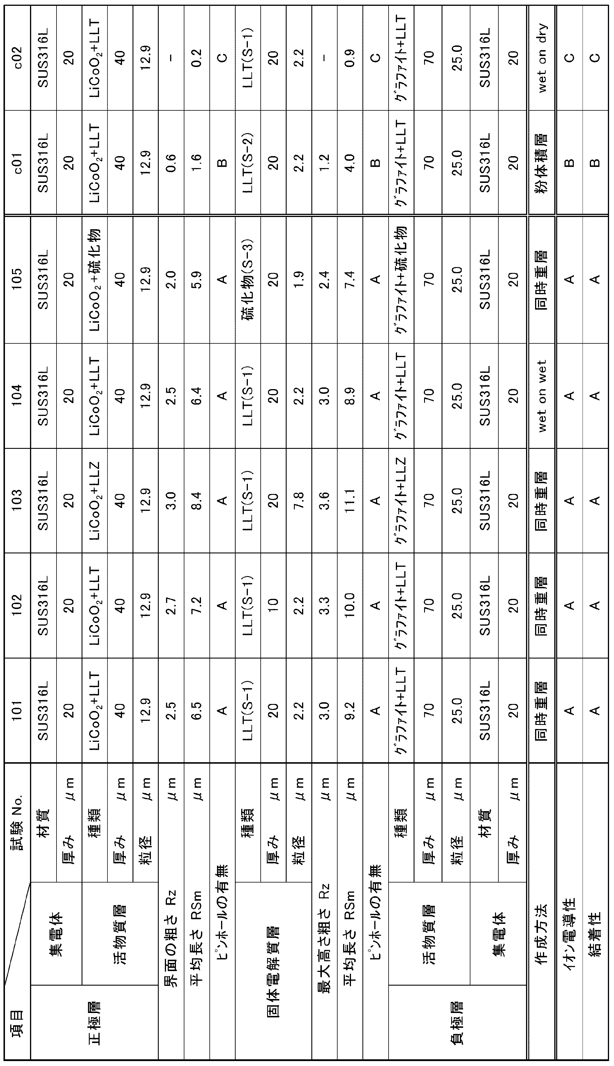
SUS316L:Ni/Cr/Mo/Fe=12/17/2.5/68.5(質量比)
LLT :Li0.33La0.55TiO3
LLZ :Li7La3Zr2O12
硫化物 :硫化物系無機固体電解質(Li-P-S系ガラス)
同時重層:同時重層方式
wet on wet:ウエット・オン・ウエット方式
wet on dry:ウエット・オン・ドライ方式
紛体積層:紛体積層方式
粒径:平均粒径
平均長さ:粗さ曲線要素の平均長さ
各パラメータの測定方法は下記のとおりである。
<表面粗さ測定法>
正極層/無機固体電解質層/負極層からなる積層体の断面をSEMを用いて1000倍で撮影する。断面はDiATOME社製ダイヤモンドナイフで切断し、観察に適した部分を選定した。測定箇所は、20箇所として、その平均値を採用した。得られた画像の正極層あるいは負極層と無機固体電解質層の界面の曲線を求める(図4では正極層の例で求める曲線を線で例示した)。得られた粗さ曲線についてJIS B0601-2013の最大高さ粗さRzの定義(図5)に従い基準長さ200μmにおける粗さ曲線の最大山高さRpと最大谷深さRvの和(Rz=Rp+Rv)を求めた。
RSmも同様にJIS B0601-2013に沿うこととし、長さ200μmの範囲の線分を任意に50箇所選定して測定した。評価結果はその平均値を採用した。
<表面粗さ測定法>
正極層/無機固体電解質層/負極層からなる積層体の断面をSEMを用いて1000倍で撮影する。断面はDiATOME社製ダイヤモンドナイフで切断し、観察に適した部分を選定した。測定箇所は、20箇所として、その平均値を採用した。得られた画像の正極層あるいは負極層と無機固体電解質層の界面の曲線を求める(図4では正極層の例で求める曲線を線で例示した)。得られた粗さ曲線についてJIS B0601-2013の最大高さ粗さRzの定義(図5)に従い基準長さ200μmにおける粗さ曲線の最大山高さRpと最大谷深さRvの和(Rz=Rp+Rv)を求めた。
RSmも同様にJIS B0601-2013に沿うこととし、長さ200μmの範囲の線分を任意に50箇所選定して測定した。評価結果はその平均値を採用した。
<ピンホールの測定法>
例えば集電体上に正極層形成用スラリーを塗布、乾燥した後、無機固体電解質層形成用スラリーを塗布、乾燥した場合、乾燥後の無機固体電解質層の表面をSEMを用いて200倍(日立ハイテクノロジーズ製 TM-1000)で撮影する。測定する対象領域は900μm×700μmである。
任意に選択した50箇所の領域についてピンホールの数を数え、1mm2あたりに平均化して下記A~Cの評価を行った。
A:ピンホールが確認されなかった。
B:16個以下確認された。
C:17個以上確認された。
例えば集電体上に正極層形成用スラリーを塗布、乾燥した後、無機固体電解質層形成用スラリーを塗布、乾燥した場合、乾燥後の無機固体電解質層の表面をSEMを用いて200倍(日立ハイテクノロジーズ製 TM-1000)で撮影する。測定する対象領域は900μm×700μmである。
任意に選択した50箇所の領域についてピンホールの数を数え、1mm2あたりに平均化して下記A~Cの評価を行った。
A:ピンホールが確認されなかった。
B:16個以下確認された。
C:17個以上確認された。
<粒径、粒度分布の測定方法>
JIS8826:2005に準じた動的光散乱式粒径分布測定装置(株式会社堀場製作所製LB-500)を用いて、無機固体電解質粒子分散物を20mlサンプル瓶に分取し、トルエンにより固形分濃度が0.2質量%になるように希釈調整し、温度25℃で2mlの測定用石英セルを使用してデータ取り込みを50回行い、得られた体積基準の算術平均を平均粒子径とした。
JIS8826:2005に準じた動的光散乱式粒径分布測定装置(株式会社堀場製作所製LB-500)を用いて、無機固体電解質粒子分散物を20mlサンプル瓶に分取し、トルエンにより固形分濃度が0.2質量%になるように希釈調整し、温度25℃で2mlの測定用石英セルを使用してデータ取り込みを50回行い、得られた体積基準の算術平均を平均粒子径とした。
<電極結着性の評価>
二次電池用電極シート作製工程において、負極集電体SUS316L箔を付与する前の電極シート(負極用組成物を塗布・乾燥させた状態)の電極シートを用いて結着性の評価を行った。乾燥後の負極用組成物に粘着テープ(セロハンテープ(「CT24」,ニチバン(株)製))を貼り、一定速度で引き剥がした際に、剥離した面積を目視で確認した。剥離しなかった部分の面積の比率を下記のように評価した。
A:100%
B:95%以上100%未満
C:95%未満
二次電池用電極シート作製工程において、負極集電体SUS316L箔を付与する前の電極シート(負極用組成物を塗布・乾燥させた状態)の電極シートを用いて結着性の評価を行った。乾燥後の負極用組成物に粘着テープ(セロハンテープ(「CT24」,ニチバン(株)製))を貼り、一定速度で引き剥がした際に、剥離した面積を目視で確認した。剥離しなかった部分の面積の比率を下記のように評価した。
A:100%
B:95%以上100%未満
C:95%未満
<イオン伝導度の測定>
上記で得られた二次電池用電極シートを直径14.5mmの円板状に打ち抜き、スペーサーとワッシャーを組み込んだステンレス製の2032型コインケースに入れてコイン電池を作製した。コイン電池の外部より、電極間に500kgf/cm2の圧力をかけることができるジグに挟み、30℃の恒温槽中で交流インピーダンス法により求めた。結果を下記の評価基準に沿って表1に示した。
A:比較例c01を基準としこの+10%を超えるもの
B:比較例c01を基準としこの伝導度以上であり+10%以下のもの
C:比較例c01を基準としこの伝導度以下のもの
上記で得られた二次電池用電極シートを直径14.5mmの円板状に打ち抜き、スペーサーとワッシャーを組み込んだステンレス製の2032型コインケースに入れてコイン電池を作製した。コイン電池の外部より、電極間に500kgf/cm2の圧力をかけることができるジグに挟み、30℃の恒温槽中で交流インピーダンス法により求めた。結果を下記の評価基準に沿って表1に示した。
A:比較例c01を基準としこの+10%を超えるもの
B:比較例c01を基準としこの伝導度以上であり+10%以下のもの
C:比較例c01を基準としこの伝導度以下のもの
<分子量の測定>
ゲルパーミエーションクロマトグラフィー(GPC)によって標準ポリスチレン換算の重量平均分子量を計測した。測定法としては、下記条件の方法により測定した。
(条件)
カラム:TOSOH TSKgel Super HZM-H、TOSOH TSKgel Super HZ4000、TOSOH TSKgel Super HZ2000をつないだカラムを用いる
キャリア:テトラヒドロフラン
ゲルパーミエーションクロマトグラフィー(GPC)によって標準ポリスチレン換算の重量平均分子量を計測した。測定法としては、下記条件の方法により測定した。
(条件)
カラム:TOSOH TSKgel Super HZM-H、TOSOH TSKgel Super HZ4000、TOSOH TSKgel Super HZ2000をつないだカラムを用いる
キャリア:テトラヒドロフラン
<粘度の測定方法>
固体電解質組成物 50mLを東京計器社製のB型粘度計BL2で測定した。サンプルは予め測定開始温度にて温度が一定となるまで保温しておき、測定はその後に開始した。測定温度は25℃とした。
固体電解質組成物 50mLを東京計器社製のB型粘度計BL2で測定した。サンプルは予め測定開始温度にて温度が一定となるまで保温しておき、測定はその後に開始した。測定温度は25℃とした。
<ペーストの固形分濃度の測定方法>
島津製作所製赤外線加熱乾燥質量測定機MOC-102Hを用いてペーストの加熱乾燥前後の重量から減少分を溶剤として固形分を算出した。
島津製作所製赤外線加熱乾燥質量測定機MOC-102Hを用いてペーストの加熱乾燥前後の重量から減少分を溶剤として固形分を算出した。
本発明をその実施態様とともに説明したが、我々は特に指定しない限り我々の発明を説明のどの細部においても限定しようとするものではなく、添付の請求の範囲に示した発明の精神と範囲に反することなく幅広く解釈されるべきであると考える。
本願は、2014年3月28日に日本国で特許出願された特願2014-070093及び2015年2月19日に日本国で特許出願された特願2015-030377に基づく優先権を主張するものであり、これらはここに参照してその内容を本明細書の記載の一部として取り込む。
1 負極集電体
2 負極活物質層
3 無機固体電解質層
4 正極活物質層
5 正極集電体
6 作動部位
10 全固体二次電池
20 ノズル
2A 下層用塗布液
2B 上層用塗布液
21 支持体(金属箔)
22 塗布膜下層
23 塗布膜上層
30A,30B,30C ノズル
3A 下層用塗布液
3B 中層用塗布液
3C 上層用塗布液
31 支持体(金属箔)
32 塗布膜下層
33 塗布膜中層
34 塗布膜上層
2 負極活物質層
3 無機固体電解質層
4 正極活物質層
5 正極集電体
6 作動部位
10 全固体二次電池
20 ノズル
2A 下層用塗布液
2B 上層用塗布液
21 支持体(金属箔)
22 塗布膜下層
23 塗布膜上層
30A,30B,30C ノズル
3A 下層用塗布液
3B 中層用塗布液
3C 上層用塗布液
31 支持体(金属箔)
32 塗布膜下層
33 塗布膜中層
34 塗布膜上層
Claims (13)
- 正極活物質層と負極活物質層と前記両層の間に介在する無機固体電解質層とを有する全固体二次電池であって、
上記無機固体電解質層がイオン伝導性の無機固体電解質を含み、
上記正極活物質層と無機固体電解質層の界面または負極活物質層と無機固体電解質層の界面の少なくとも一方の最大高さ粗さRzが1.5μm~5μmである全固体二次電池。
最大高さ粗さは、JIS B0601-2013で規定される粗さ曲線の最大高さ粗さRzを意味する。 - 上記正極活物質層、無機固体電解質層、および負極活物質層のいずれの層においても、ピンホールの数が1mm2当たり16個以下に規制された請求項1に記載の全固体二次電池。
- 上記正極活物質層または負極活物質層がスラリーの塗布により形成され、上記正極活物質層または負極活物質層が湿潤状態であるうちに、上記無機固体電解質層を形成するためのスラリーを塗布して上記無機固体電解質層を形成した請求項1または2に記載の全固体二次電池。
- 上記正極活物質層および負極活物質層の厚さが1μm以上1000μm以下である請求項1~3のいずれか1項に記載の全固体二次電池。
- 上記無機固体電解質層の厚さが1μm以上1000μm以下である請求項1~4のいずれか1項に記載の全固体二次電池。
- 上記正極活物質層と無機固体電解質層の界面または負極活物質層と無機固体電解質層界面の少なくとも一方の最大高さ粗さRzが3μm以下である請求項1~5のいずれか1項に記載の全固体二次電池。
- 上記無機固体電解質が硫化物系無機固体電解質である請求項1~6のいずれか1項に記載の全固体二次電池。
- 上記無機固体電解質が酸化物系無機固体電解質である請求項1~6のいずれか1項に記載の全固体二次電池。
- 上記無機固体電解質が下記式の化合物から選ばれる請求項8に記載の全固体二次電池。
・LixLayTiO3
x=0.3~0.7、y=0.3~0.7
・Li7La3Zr2O12
・Li3.5Zn0.25GeO4
・LiTi2P3O12、
・Li1+x+y(Al,Ga)x(Ti,Ge)2-xSiyP3-yO12
0≦x≦1、0≦y≦1
・Li3PO4
・LiPON
・LiPOD
Dは、Ti、V、Cr、Mn、Fe、Co、Ni、Cu、
Zr、Nb、Mo、Ru、Ag、Ta、W、Pt、及びAu
から選ばれた少なくとも1種
・LiAON
Aは、Si、B、Ge、Al、C、Ga等から選ばれた
少なくとも1種 - 上記正極活物質層、負極活物質層、および無機固体電解質層の少なくとも1層がバインダーを含有する請求項1~9のいずれか1項に記載の全固体二次電池。
- 正極活物質層または負極活物質層の上側に無機固体電解質層を塗布法により形成する製造方法であって、
集電体上に正極活物質層または負極活物質層を形成するためのスラリーを塗布する工程、得られた正極活物質層または負極活物質層が湿潤状態であるうちに、無機固体電解質層を形成するためのスラリーを塗布する工程を有する電池用電極シートの製造方法。 - 上記正極活物質層または負極活物質層のスラリーの塗布と、無機固体電解質層のスラリーの塗布とを同時または逐次に行う請求項11に記載の電池用電極シートの製造方法。
- 請求項11または12に記載の電池用電極シートの製造方法を介して、全固体二次電池を製造する全固体二次電池の製造方法。
Applications Claiming Priority (4)
| Application Number | Priority Date | Filing Date | Title |
|---|---|---|---|
| JP2014070093 | 2014-03-28 | ||
| JP2014-070093 | 2014-03-28 | ||
| JP2015-030377 | 2015-02-19 | ||
| JP2015030377A JP2015195183A (ja) | 2014-03-28 | 2015-02-19 | 全固体二次電池、電池用電極シートの製造方法および全固体二次電池の製造方法 |
Publications (1)
| Publication Number | Publication Date |
|---|---|
| WO2015147280A1 true WO2015147280A1 (ja) | 2015-10-01 |
Family
ID=54195784
Family Applications (1)
| Application Number | Title | Priority Date | Filing Date |
|---|---|---|---|
| PCT/JP2015/059678 Ceased WO2015147280A1 (ja) | 2014-03-28 | 2015-03-27 | 全固体二次電池、電池用電極シートの製造方法および全固体二次電池の製造方法 |
Country Status (2)
| Country | Link |
|---|---|
| JP (1) | JP2015195183A (ja) |
| WO (1) | WO2015147280A1 (ja) |
Cited By (9)
| Publication number | Priority date | Publication date | Assignee | Title |
|---|---|---|---|---|
| WO2018062264A1 (ja) * | 2016-09-29 | 2018-04-05 | 日本電気株式会社 | 電極および二次電池 |
| CN110165300A (zh) * | 2018-02-14 | 2019-08-23 | 丰田自动车株式会社 | 全固体电池的制造方法 |
| US10446841B2 (en) | 2017-03-23 | 2019-10-15 | Kabushiki Kaisha Toshiba | Electrode composite, secondary battery, battery pack and vehicle |
| CN110383559A (zh) * | 2017-06-28 | 2019-10-25 | 日本电气硝子株式会社 | 全固体钠离子二次电池 |
| CN111668535A (zh) * | 2020-07-03 | 2020-09-15 | 清陶(昆山)能源发展有限公司 | 一种固态电解质粗糙度调整方法 |
| CN112385069A (zh) * | 2018-07-13 | 2021-02-19 | 日立造船株式会社 | 全固态二次电池的制造设备 |
| CN112448024A (zh) * | 2019-09-02 | 2021-03-05 | 中南大学 | 锂金属电池的人造固体电解质界面膜、复合集流体、锂金属负极及其制备方法 |
| CN113363593A (zh) * | 2020-03-03 | 2021-09-07 | 太阳诱电株式会社 | 全固态电池及其制造方法 |
| US12183881B2 (en) | 2016-12-21 | 2024-12-31 | Corning Incorporated | Doped-zirconia ceramic ribbon |
Families Citing this family (23)
| Publication number | Priority date | Publication date | Assignee | Title |
|---|---|---|---|---|
| JP6819941B2 (ja) * | 2014-12-16 | 2021-01-27 | エルジー・ケム・リミテッド | Ptc物質を含む二次電池用電極を製造する方法及びそれにより製造される電極 |
| JP6264350B2 (ja) * | 2015-09-24 | 2018-01-24 | トヨタ自動車株式会社 | 電極積層体及び全固体電池の製造方法 |
| JP6761992B2 (ja) * | 2015-12-11 | 2020-09-30 | 国立大学法人豊橋技術科学大学 | 電極及びその製造方法並びに全固体型リチウムイオン電池 |
| JP6786231B2 (ja) | 2016-03-16 | 2020-11-18 | 株式会社東芝 | リチウムイオン二次電池用積層体、リチウムイオン二次電池、電池パック及び車両 |
| JP6654769B2 (ja) * | 2017-02-01 | 2020-02-26 | 平井工業株式会社 | 塗工装置、塗工方法、電池の製造方法 |
| JP6955881B2 (ja) * | 2017-03-28 | 2021-10-27 | Fdk株式会社 | 全固体電池、および全固体電池の製造方法 |
| JP6729796B2 (ja) | 2017-04-04 | 2020-07-22 | 株式会社村田製作所 | 全固体電池、電子機器、電子カード、ウェアラブル機器および電動車両 |
| JP7075726B2 (ja) * | 2017-05-30 | 2022-05-26 | 三星電子株式会社 | 全固体二次電池及び全固体二次電池の製造方法 |
| US10886515B2 (en) | 2017-05-30 | 2021-01-05 | Samsung Electronics Co., Ltd. | All-solid secondary battery and method of preparing the same |
| JP6985426B2 (ja) * | 2018-02-05 | 2021-12-22 | 富士フイルム株式会社 | 固体電解質含有シート、全固体二次電池用電極シート、全固体二次電池、電子機器及び電気自動車、並びに、これらの製造方法 |
| JP6808667B2 (ja) | 2018-03-01 | 2021-01-06 | 株式会社東芝 | 積層体、積層体の製造方法及び二次電池 |
| JP6965839B2 (ja) * | 2018-07-12 | 2021-11-10 | トヨタ自動車株式会社 | 二次電池の充電方法 |
| WO2020059550A1 (ja) * | 2018-09-18 | 2020-03-26 | 富士フイルム株式会社 | 全固体二次電池用積層部材の製造方法及び全固体二次電池の製造方法 |
| KR102745343B1 (ko) * | 2018-10-30 | 2024-12-23 | 삼성전자주식회사 | 전고체 이차전지, 및 전고체 이차전지의 제조 방법 |
| CN111799437B (zh) * | 2019-04-08 | 2021-07-09 | 宁德时代新能源科技股份有限公司 | 正极极片及钠离子电池 |
| CN111554967B (zh) * | 2020-03-06 | 2021-02-23 | 清陶(昆山)能源发展有限公司 | 一种全固态电池及其制备方法 |
| JP2021180074A (ja) * | 2020-05-11 | 2021-11-18 | 株式会社アルバック | 薄膜リチウム二次電池及び薄膜リチウム二次電池の製造方法 |
| KR102899216B1 (ko) * | 2020-11-19 | 2025-12-11 | 삼성전자주식회사 | 전고체 전지 및 그 제조방법 |
| JP7708571B2 (ja) * | 2021-03-29 | 2025-07-15 | Tdk株式会社 | 固体電解質材および全固体電池 |
| JP2022158106A (ja) * | 2021-04-01 | 2022-10-17 | マクセル株式会社 | 全固体二次電池及びその製造方法 |
| JP7582245B2 (ja) * | 2022-04-25 | 2024-11-13 | トヨタ自動車株式会社 | 全固体電池 |
| JP2024122257A (ja) * | 2023-02-28 | 2024-09-09 | 三桜工業株式会社 | 全固体電池の製造方法 |
| KR20260016073A (ko) * | 2024-07-26 | 2026-02-03 | 주식회사 엘지에너지솔루션 | 전고체 전지용 양극 및 이를 포함하는 전고체 전지 |
Citations (8)
| Publication number | Priority date | Publication date | Assignee | Title |
|---|---|---|---|---|
| JPH11214034A (ja) * | 1998-01-23 | 1999-08-06 | Sony Corp | 固体電解質電池及びその製造方法 |
| JP2000340257A (ja) * | 1998-12-03 | 2000-12-08 | Sumitomo Electric Ind Ltd | リチウム二次電池 |
| JP2003530659A (ja) * | 1999-04-09 | 2003-10-14 | ビーエーエスエフ アクチェンゲゼルシャフト | リチウムイオンバッテリーでの使用に適当な複合材料を製造するウェット・オン・ウェット塗布法 |
| JP2009289534A (ja) * | 2008-05-28 | 2009-12-10 | Idemitsu Kosan Co Ltd | 全固体リチウム電池用電極、全固体リチウム電池および装置 |
| JP2010113819A (ja) * | 2008-11-04 | 2010-05-20 | Konica Minolta Holdings Inc | 二次電池、その製造方法、及びラミネート型二次電池 |
| JP2012221749A (ja) * | 2011-04-08 | 2012-11-12 | Sumitomo Electric Ind Ltd | 非水電解質電池 |
| WO2013035387A1 (ja) * | 2011-09-09 | 2013-03-14 | ファイラックインターナショナル株式会社 | 固体型二次電池の製造方法及び当該製造方法に基づく固体型二次電池 |
| JP2014035818A (ja) * | 2012-08-07 | 2014-02-24 | Tdk Corp | 全固体リチウムイオン二次電池 |
-
2015
- 2015-02-19 JP JP2015030377A patent/JP2015195183A/ja active Pending
- 2015-03-27 WO PCT/JP2015/059678 patent/WO2015147280A1/ja not_active Ceased
Patent Citations (8)
| Publication number | Priority date | Publication date | Assignee | Title |
|---|---|---|---|---|
| JPH11214034A (ja) * | 1998-01-23 | 1999-08-06 | Sony Corp | 固体電解質電池及びその製造方法 |
| JP2000340257A (ja) * | 1998-12-03 | 2000-12-08 | Sumitomo Electric Ind Ltd | リチウム二次電池 |
| JP2003530659A (ja) * | 1999-04-09 | 2003-10-14 | ビーエーエスエフ アクチェンゲゼルシャフト | リチウムイオンバッテリーでの使用に適当な複合材料を製造するウェット・オン・ウェット塗布法 |
| JP2009289534A (ja) * | 2008-05-28 | 2009-12-10 | Idemitsu Kosan Co Ltd | 全固体リチウム電池用電極、全固体リチウム電池および装置 |
| JP2010113819A (ja) * | 2008-11-04 | 2010-05-20 | Konica Minolta Holdings Inc | 二次電池、その製造方法、及びラミネート型二次電池 |
| JP2012221749A (ja) * | 2011-04-08 | 2012-11-12 | Sumitomo Electric Ind Ltd | 非水電解質電池 |
| WO2013035387A1 (ja) * | 2011-09-09 | 2013-03-14 | ファイラックインターナショナル株式会社 | 固体型二次電池の製造方法及び当該製造方法に基づく固体型二次電池 |
| JP2014035818A (ja) * | 2012-08-07 | 2014-02-24 | Tdk Corp | 全固体リチウムイオン二次電池 |
Cited By (19)
| Publication number | Priority date | Publication date | Assignee | Title |
|---|---|---|---|---|
| US11469408B2 (en) | 2016-09-29 | 2022-10-11 | Nec Corporation | Electrode and secondary battery |
| CN109792038A (zh) * | 2016-09-29 | 2019-05-21 | 日本电气株式会社 | 电极和二次电池 |
| JPWO2018062264A1 (ja) * | 2016-09-29 | 2019-07-11 | 日本電気株式会社 | 電極および二次電池 |
| WO2018062264A1 (ja) * | 2016-09-29 | 2018-04-05 | 日本電気株式会社 | 電極および二次電池 |
| JP7319008B2 (ja) | 2016-09-29 | 2023-08-01 | 日本電気株式会社 | 電極および二次電池 |
| US12537225B2 (en) | 2016-12-21 | 2026-01-27 | Corning Incorporated | Roll to roll sintering system for wide inorganic tape material and sintered articles |
| US12183881B2 (en) | 2016-12-21 | 2024-12-31 | Corning Incorporated | Doped-zirconia ceramic ribbon |
| US10446841B2 (en) | 2017-03-23 | 2019-10-15 | Kabushiki Kaisha Toshiba | Electrode composite, secondary battery, battery pack and vehicle |
| CN110383559B (zh) * | 2017-06-28 | 2023-05-26 | 日本电气硝子株式会社 | 全固体钠离子二次电池 |
| CN110383559A (zh) * | 2017-06-28 | 2019-10-25 | 日本电气硝子株式会社 | 全固体钠离子二次电池 |
| CN110165300B (zh) * | 2018-02-14 | 2022-06-14 | 丰田自动车株式会社 | 全固体电池的制造方法 |
| CN110165300A (zh) * | 2018-02-14 | 2019-08-23 | 丰田自动车株式会社 | 全固体电池的制造方法 |
| CN112385069A (zh) * | 2018-07-13 | 2021-02-19 | 日立造船株式会社 | 全固态二次电池的制造设备 |
| CN112448024A (zh) * | 2019-09-02 | 2021-03-05 | 中南大学 | 锂金属电池的人造固体电解质界面膜、复合集流体、锂金属负极及其制备方法 |
| CN113363593A (zh) * | 2020-03-03 | 2021-09-07 | 太阳诱电株式会社 | 全固态电池及其制造方法 |
| CN113363593B (zh) * | 2020-03-03 | 2024-04-26 | 太阳诱电株式会社 | 全固态电池及其制造方法 |
| US12119454B2 (en) | 2020-03-03 | 2024-10-15 | Taiyo Yuden Co., Ltd. | All solid battery and manufacturing method of the same |
| CN111668535B (zh) * | 2020-07-03 | 2021-02-19 | 清陶(昆山)能源发展有限公司 | 一种固态电解质粗糙度调整方法 |
| CN111668535A (zh) * | 2020-07-03 | 2020-09-15 | 清陶(昆山)能源发展有限公司 | 一种固态电解质粗糙度调整方法 |
Also Published As
| Publication number | Publication date |
|---|---|
| JP2015195183A (ja) | 2015-11-05 |
Similar Documents
| Publication | Publication Date | Title |
|---|---|---|
| WO2015147280A1 (ja) | 全固体二次電池、電池用電極シートの製造方法および全固体二次電池の製造方法 | |
| US11817548B2 (en) | All solid-state secondary battery, inorganic solid electrolyte particles, solid electrolyte composition, electrode sheet for battery, and method for manufacturing all solid-state secondary battery | |
| JP6721669B2 (ja) | 固体電解質組成物、全固体二次電池用電極シートおよび全固体二次電池、並びに、全固体二次電池用電極シートおよび全固体二次電池の製造方法 | |
| US11605833B2 (en) | Solid electrolyte composition and method of manufacturing the same, solid electrolyte-containing sheet, electrode sheet for all-solid state secondary battery, and method of manufacturing all-solid state secondary battery | |
| JP6318099B2 (ja) | 固体電解質組成物およびこれを用いた電池用電極シートならびに電池用電極シートおよび全固体二次電池の製造方法 | |
| JP5333184B2 (ja) | 全固体二次電池 | |
| JP6452814B2 (ja) | 正極用材料、全固体二次電池用電極シートおよび全固体二次電池ならびに全固体二次電池用電極シートおよび全固体二次電池の製造方法 | |
| JP6295333B2 (ja) | 全固体二次電池、固体電解質組成物、これを用いた電池用電極シート、電池用電極シートの製造方法および全固体二次電池の製造方法 | |
| US20160359194A1 (en) | Solid electrolyte composition, method for manufacturing the same, and electrode sheet for battery and all-solid-state secondary battery in which solid electrolyte composition is used | |
| JP6876820B2 (ja) | 活物質層形成用組成物及びその製造方法、並びに、全固体二次電池用電極シート及び全固体二次電池の製造方法 | |
| CN112602209B (zh) | 负极用组合物、全固态二次电池、全固态二次电池用负极片以及后两者的制造方法 | |
| JPWO2018168550A1 (ja) | 全固体二次電池及びその製造方法、並びに全固体二次電池用固体電解質シート及び全固体二次電池用正極活物質シート | |
| JPWO2020059550A1 (ja) | 全固体二次電池用積層部材の製造方法及び全固体二次電池の製造方法 | |
| JP7119214B2 (ja) | 全固体二次電池及びその製造方法 | |
| KR102757586B1 (ko) | 전고체 이차 전지용 시트 및 전고체 이차 전지의 제조 방법, 및, 전고체 이차 전지용 시트 및 전고체 이차 전지 | |
| CN115917818B (zh) | 全固态二次电池、该电池用片材和两者的制造方法 | |
| JP2021068621A (ja) | 固体電池、固体電池の正極活物質層製造用組成物、および固体電池の正極活物質層の製造方法 | |
| US12040445B2 (en) | Solid electrolyte composition, solid electrolyte-containing sheet, all-solid state secondary battery, and methods for manufacturing solid electrolyte-containing sheet and all-solid state secondary battery | |
| CN116504913A (zh) | 正极 | |
| CN121014116A (zh) | 非水电解液二次电池的制造方法及非水电解液二次电池 | |
| CN121153120A (zh) | 电极形成用浆料、非水电解液二次电池及其制造方法、以及分散剂 |
Legal Events
| Date | Code | Title | Description |
|---|---|---|---|
| 121 | Ep: the epo has been informed by wipo that ep was designated in this application |
Ref document number: 15769332 Country of ref document: EP Kind code of ref document: A1 |
|
| NENP | Non-entry into the national phase | ||
| 122 | Ep: pct application non-entry in european phase |
Ref document number: 15769332 Country of ref document: EP Kind code of ref document: A1 |