WO2015146753A1 - 走行装置 - Google Patents
走行装置 Download PDFInfo
- Publication number
- WO2015146753A1 WO2015146753A1 PCT/JP2015/058126 JP2015058126W WO2015146753A1 WO 2015146753 A1 WO2015146753 A1 WO 2015146753A1 JP 2015058126 W JP2015058126 W JP 2015058126W WO 2015146753 A1 WO2015146753 A1 WO 2015146753A1
- Authority
- WO
- WIPO (PCT)
- Prior art keywords
- rolling wheel
- width direction
- projection
- drive
- guide
- Prior art date
- Legal status (The legal status is an assumption and is not a legal conclusion. Google has not performed a legal analysis and makes no representation as to the accuracy of the status listed.)
- Ceased
Links
Images


Classifications
-
- B—PERFORMING OPERATIONS; TRANSPORTING
- B62—LAND VEHICLES FOR TRAVELLING OTHERWISE THAN ON RAILS
- B62D—MOTOR VEHICLES; TRAILERS
- B62D55/00—Endless track vehicles
- B62D55/08—Endless track units; Parts thereof
- B62D55/18—Tracks
- B62D55/24—Tracks of continuously flexible type, e.g. rubber belts
- B62D55/244—Moulded in one piece, with either smooth surfaces or surfaces having projections, e.g. incorporating reinforcing elements
-
- B—PERFORMING OPERATIONS; TRANSPORTING
- B62—LAND VEHICLES FOR TRAVELLING OTHERWISE THAN ON RAILS
- B62D—MOTOR VEHICLES; TRAILERS
- B62D55/00—Endless track vehicles
- B62D55/08—Endless track units; Parts thereof
- B62D55/12—Arrangement, location, or adaptation of driving sprockets
- B62D55/125—Final drives
-
- B—PERFORMING OPERATIONS; TRANSPORTING
- B62—LAND VEHICLES FOR TRAVELLING OTHERWISE THAN ON RAILS
- B62D—MOTOR VEHICLES; TRAILERS
- B62D55/00—Endless track vehicles
- B62D55/08—Endless track units; Parts thereof
- B62D55/14—Arrangement, location, or adaptation of rollers
Definitions
- the present disclosure relates to a traveling device including a sprocket that is rotatably supported, a rubber crawler that is rotatable around the sprocket, and a plurality of rolling wheels that roll on the inner circumferential surface of the rubber crawler. Concerned.
- Such a traveling device is provided, for example, as a pair on both sides in the width direction of the vehicle, and the vehicle travels by driving the pair of traveling devices, and the vehicle is divided by providing a difference in the number of rotations of the pair of traveling devices. It can be turned.
- the rubber crawler of the traveling device provided in such a vehicle is generally used in a vehicle for high-speed traveling because it is lightweight and has low traveling resistance and vibration as compared with a metal crawler.
- This rubber crawler is provided, for example, with a gap on the inner peripheral surface of the center portion in the width direction of an endless rubber elastic body to prevent separation of the rolling wheels, and both side portions in the width direction of the rubber elastic body.
- the rubber crawler is less rigid than a metal crawler because there is no metallic reinforcing core inside.
- the steel cord row reinforces the tensile force acting in the circumferential direction of the rubber elastic body, and the bias cord row reinforces the force (for example, twist) acting in the lateral direction of the rubber elastic body.
- a plurality of rolling wheels are rollably provided on the inner peripheral surface of such a rubber crawler. Loads such as an impact received from the ground are absorbed by the rolling wheels to reduce vibration.
- the roller has a disk-shaped first roller main body portion and a second roller main body integrated integrally opposed to each other so as to straddle the guide projections in the width direction of the rubber crawler.
- the first rolling wheel main body portion is disposed between one of the pair of drive protrusions and the guide protrusion
- the second rolling wheel main body portion is disposed between the other of the pair of drive protrusions and the guide protrusion
- the ring rolls on the inner circumferential surface of the rubber elastic body while sandwiching the guide projection between the first rolling wheel main body portion and the second rolling wheel main body portion.
- the rubber crawler rotates while circulating between a sprocket serving as a driving wheel and a driven wheel, and as the rubber crawler rotates, the rolling wheels roll on the inner circumferential surface of the rubber crawler.
- the guide projection sandwiched between the first rolling wheel main body portion and the second rolling wheel main body portion of the rolling wheel There is a risk that the rubber crawler may be damaged from the load in the width direction of the rubber crawler from the wheel. Therefore, there is a risk that the rolling wheels will be released from the rubber crawler.
- At least some embodiments of the present invention aim to provide a traveling device without fear that the guide projections of the rubber crawler are damaged and the rolling wheels are disengaged when the vehicle turns. Do.
- a traveling device A rolling wheel disposed on a widthwise central portion of an inner circumferential surface of an endless rubber crawler and straddling a guide projection and rolling on the inner circumferential surface of the rubber crawler is a side surface of the guide projection and A traveling device in surface contact with side surfaces of driving protrusions provided on both sides in the width direction of the inner circumferential surface of the rubber crawler, Side surfaces which can be surface-contacted with the side surfaces of the guide protrusion and the drive protrusion are formed at the width direction end of the rolling wheel, The side surfaces of the rolling wheel are disposed opposite to the side surfaces of the guide projection and the driving projection so that the side surfaces of the guiding projection and the side surfaces of the driving projection are brought into surface contact by swinging of the rolling wheel in the crawler width direction. Configured to be.
- the side surface of the rolling wheel comes into surface contact with the side surface of the driving protrusion along with the side surface of the guide protrusion due to the swinging of the rolling wheel in the crawler width direction.
- the guide projections and the drive projections are disposed to face each side, when a load in the rubber crawler width direction is applied to the guide projections from the rolling wheels when the rolling wheels swing, this load is Can be received by two projections. Therefore, since the load can be dispersed to the guide projection and the drive projection, it is possible to realize a traveling device capable of preventing the possibility of the wheel being detached from being damaged by damage of the guide projection.
- the rolling wheel includes a pair of rolling wheel main portions disposed opposite to each other in the width direction of the guide protrusion, Side surfaces are formed at peripheral portions on both sides in the width direction of the pair of roller main body portions, By swinging of the rolling wheel, one of the side surfaces of the pair of rolling wheel main body portions comes into surface contact with the side surface of the guide projection, and the other side surface comes into surface contact with the side surface of the driving projection.
- a gap between any one side surface of the pair of rolling wheel main portions and a side surface of the guide protrusion is a gap between any other side surface of the pair of rolling wheel main portions and a side surface of the drive protrusion. It is configured to have the same size as
- the gap between any one side surface of the pair of rolling wheel main portions and the side surface of the guide protrusion is between the other side surface of the pair of rolling wheel main portions and the side surface of the driving protrusion. Since it has the same size as the gap, the pair of rolling wheel main body portions simultaneously contact the drive protrusion and the guide protrusion, so that the deformation amounts of the drive protrusion and the guide protrusion can be made equal. In addition, it is possible to equalize the amount of wear of the contact portions of the pair of roller main body portions in contact with the drive protrusion and the guide protrusion.
- the guide protrusion and the drive protrusion disposed adjacent to each other in the width direction of the rubber crawler are formed such that the rigidity in the width direction to a load directed in the width direction is lower than that of any one of the other.
- the gap between the side surface of the guide protrusion and the drive protrusion having the lower width direction rigidity and the side surface of the rolling wheel is the side surface of the guide protrusion and the drive protrusion having the higher width direction rigidity and the side surface It is configured to be smaller than the gap between the roller and the side surface.
- the gap between the side surface of the guide protrusion and the drive protrusion having the lower rigidity in the width direction and the side surface of the rotating wheel is the same as the side surface of the guide protrusion and the drive protrusion having the higher rigidity in the width direction. Since it is smaller than the gap with the side of the ring, when the rolling wheel is swinging, if a load from the rolling wheel to the widthwise direction acts on the guide projection, the rolling wheel first strikes the low width direction rigid projection It is elastically deformed and then hits a protrusion with high width direction rigidity. Thus, the load can be received by the two guide protrusions and the drive protrusions. Therefore, the load can be dispersed to the guide protrusions and the drive protrusions, and the possibility of damage to the guide protrusions can be suppressed.
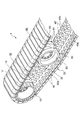
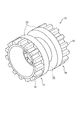
- FIG. 6 is a partial perspective view of the traveling device on the side on which the sprockets of the traveling device are disposed. It is a perspective view of a sprocket. It is a perspective view of a rolling wheel.
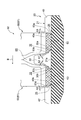
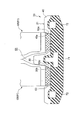
- FIG. 7 is a cross-sectional view of a portion corresponding to the II arrow view of FIG. 1 when the clearances between the rotating wheel and the rubber crawler are equal.
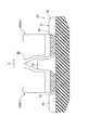
- FIG. 5 is a cross-sectional view of the rolling wheel and the rubber crawler when the rubber crawler receives a lateral load from the rolling wheel.
- FIG. 12 is a cross-sectional view of a portion corresponding to the II arrow view of FIG. 1 when the clearance between the rotating wheel and the rubber crawler is different in another embodiment. In other embodiment, it is sectional drawing of a rolling wheel and a rubber crawler when a rubber crawler is receiving the side load from a rolling wheel.
- FIGS. 1 to 8 a traveling device provided in a vehicle will be described as an example.
- the material of the component described in this embodiment, the shape, the relative arrangement, etc. are not the meaning which limits the scope of the present invention to this, but are only a mere illustration example.
- the traveling device 1 is, as shown in FIG. 1 (side view), a driving wheel 10 rotatably supported at one end in the front-rear direction of a side portion of the vehicle body (not shown).
- a driven wheel 17 rotatably supported at an end, a rubber crawler 20 wound around the driving wheel 10 and the driven wheel 17, and a plurality of rolls rolling on the lower inner peripheral surface of the rubber crawler 20 And a wheel 60.
- the drive wheel 10 is rotatable in response to a drive force from an engine or the like provided in the vehicle.
- the drive wheel 10 is provided with a pair of sprockets 11 disposed opposite to each other with a predetermined interval in the width direction, and the pair of sprockets 11 are attached to the tip of a drive shaft extending from the vehicle to form the drive wheel 10 ing.
- the teeth 12 mesh with the drive projections 40 of the rubber crawler 20 to transmit rotational force to the rubber crawler 20.
- a guide roller 13 disposed concentrically with the sprocket 11 to prevent the rubber crawler 20 from coming off the wheel. Between the guide rollers 13 of the pair of sprockets 11, there is provided a gap 15 through which the guide projection 30 provided at the center of the rubber crawler 20 in the width direction can pass. For this reason, the drive wheel 10 can transmit the rotational force of the drive wheel 10 to the rubber crawler 20 without being disengaged from the rubber crawler 20 by the pair of guide rollers 13.
- the rolling wheel 60 includes a pair of rolling wheel main body portions 61 which are disposed opposite to each other with a constant interval in the width direction, and the pair of rolling wheel main body portions 61 Is rotatably attached to the tip of a support shaft (not shown) extending from the vehicle body of the vehicle.
- the support shaft is supported movably in the vertical direction with respect to the vehicle body of the vehicle.
- An annular body 63 made of rubber is mounted on the outer peripheral surface of the wheel body 61. The annular body 63 can absorb an impact received from the road surface.
- a gap 65 through which the guide projection 30 of the rubber crawler 20 can pass is provided between the pair of roller main body portions 61.
- first rolling wheel main portion 68 the rolling wheel main portion 61 disposed outside the vehicle is referred to as “first rolling wheel main portion 68"
- second rolling wheel main portion 69 the rolling wheel main portion 61 disposed inside the vehicle is It describes as “the 2nd rolling-wheel main-body part 69.”
- a first outer sliding contact surface 63 a annularly formed along the peripheral edge portion is formed at the outer peripheral edge portion in the width direction of the annular body 63 of the first rolling wheel main body portion 68.
- the first outer sliding contact surface 63 a is formed as a flat inclined surface which is inclined inward of the first rolling wheel main body 68 as it proceeds radially outward of the first rolling wheel main body 68.
- the first outer sliding contact surface 63 a is inclined at an angle of about 80 degrees with respect to the inner peripheral surface 21 a of the rubber elastic body 21.
- the first outer sliding contact surface 63 a is disposed to face the inner surface of the drive projection 40. Details of the inner surface of the drive projection 40 will be described later.
- a first inner sliding contact surface 63b annularly formed along the peripheral edge portion is formed at the inner peripheral edge portion in the width direction of the annular body 63 of the first rolling wheel main body portion 68.
- the first inner sliding contact surface 63 b is formed as a flat inclined surface which inclines inward of the first rolling wheel main body 68 as it proceeds radially outward of the first rolling wheel main body 68.
- the first inner sliding contact surface 63 b is inclined at an angle of about 50 degrees with respect to the inner peripheral surface 21 a of the rubber elastic body 21.
- the first inner sliding contact surface 63 b is disposed to face the outer surface of the guide protrusion 30. Details of the outer surface of the guide protrusion 30 will be described later.
- a second outer sliding contact surface 63c annularly formed along the peripheral edge portion is formed at the outer peripheral edge portion in the width direction of the annular body 63 of the second roller main body portion 69.
- the second outer sliding contact surface 63 c is formed as a flat inclined surface which is inclined inward of the second rolling wheel main body 69 as it proceeds radially outward of the second rolling wheel main body 69.
- the second outer sliding contact surface 63c is inclined at an angle of about 50 degrees with respect to the inner peripheral surface 21a of the rubber elastic body 21.
- the second outer sliding contact surface 63 c is disposed to face the inner surface of the guide projection 30. Details of the inner surface of the guide protrusion 30 will be described later.
- a second inner sliding contact surface 63 d annularly formed along the peripheral edge portion is formed at the outer peripheral edge portion in the width direction of the annular body 63 of the second roller main body portion 69.
- the second inner sliding contact surface 63 d is formed as a flat inclined surface which inclines inward of the second rolling wheel main body portion 69 as it proceeds radially outward of the second rolling wheel main body portion 69.
- the second inner sliding contact surface 63 d is inclined at an angle of about 80 degrees with respect to the inner peripheral surface 21 a of the rubber elastic body 21.
- the second inner sliding contact surface 63 d is disposed to face the inner surface of the drive projection 40. Details of the inner surface of the drive projection 40 will be described later.
- the rubber crawler 20 as shown in FIG. 2 and FIG. 5, is provided with a constant interval in the circumferential direction at the central portion in the width direction of the endless rubber elastic body 21 and the inner peripheral surface 21a of the rubber elastic body 21. Are provided with a constant pitch in the circumferential direction on both widthwise outer side portions of the inner peripheral surface 21a of the rubber elastic body 21 so as to mesh with the sprocket 11 And a driving protrusion 40.
- the rubber elastic body 21 is made of rubber, is endless, and is formed in a band shape.
- a plurality of lugs 22 are provided on the outer peripheral surface 21 b of the rubber elastic body 21 so as to protrude radially outward and have an interval in the circumferential direction of the rubber elastic body 21.
- the guide projection 30 provided on the inner circumferential surface 21 a of the rubber elastic body 21 is formed in a substantially rectangular parallelepiped shape extending in a direction substantially orthogonal to the inner circumferential surface 21 a.
- the guide protrusion 30 is formed to be gradually tapered as it deviates from the inner circumferential surface 21 a of the rubber elastic body 21 in a side view. For this reason, when the rubber crawler 20 rotates while being bent to the sprocket 11, the guide projections 30 adjacent in the circumferential direction of the rubber crawler 20 are prevented from coming in contact with each other.
- a guide protrusion outer side surface 30a is formed on the outer side in the width direction of the root side of the guide protrusion 30 so as to face the first inner sliding contact surface 63b of the first rolling wheel main body 68 of the rolling wheel 60.
- the guide projection outer side surface 30a is formed to extend substantially in parallel with the first inner sliding contact surface 63b.
- a predetermined gap 32 is formed between the guide protrusion outer side surface 30a and the first inner sliding contact surface 63b. Details of the size A1 of the gap 32 will be described later.
- a guide projection inner side surface 30b is formed opposite to the second outer sliding contact surface 63c of the second rolling wheel main body 69 of the rolling wheel 60.
- the guide projection inner side surface 30b is formed to extend substantially in parallel with the second outer sliding contact surface 63c.
- a predetermined gap 33 is formed between the guide projection inner side surface 30b and the second outer sliding contact surface 63c. Details of the size A2 of the gap 33 will be described later.
- the guide projection 30 has such a size that it can pass in the gap 15 between the pair of sprockets 11 and in the gap 65 between the pair of rolling wheel bodies 61 of the rolling wheels 60, and the rolling wheel 60 is removed from the rubber crawler 20. It has a height that can be restricted from turning.
- the drive protrusions 40 and 40 'provided on both sides in the width direction of the inner peripheral surface 21a of the rubber elastic body 21 are formed to be gradually tapered as they move away from the inner peripheral surface 21a of the rubber elastic body 21 in side view It is formed in a horizontally long rectangular shape in plan view.
- the drive protrusion inner side outer surface 40a extending in the vertical direction is formed.
- the drive projection inner side surface outside 40 a is formed in a planar shape, and is disposed to face the first outer sliding contact surface 63 a of the first rolling wheel main body 68.
- the drive projection inner side surface outside 40a is inclined so as to be inclined outward in the width direction as it moves upward, is formed in a planar shape, and is disposed to face the first outer sliding contact surface 63a of the first rolling wheel main body 68.
- the drive projection inner side surface outside 40a extends substantially parallel to the first outer sliding contact surface 63a, and a gap 64 is formed between the drive projection inner side outer surface 40a and the first outer sliding contact surface 63a. Details of the size A3 of the gap 33 will be described later.
- an inner side surface 40 b of the drive protrusion inner side extending in the vertical direction is formed at the width direction inner end of the drive protrusion 40 ′ provided on the inner side in the width direction of the rubber elastic body 21.
- the inner side 40b of the drive projection inner surface is formed in a planar shape, and is disposed to face the second inner sliding contact surface 63d of the second rolling wheel main body 69.
- the inner side 40b of the drive projection is inclined so as to be inclined outward in the width direction as it moves upward, is formed in a planar shape, and is disposed to face the second inner sliding contact surface 63d of the second rolling wheel main body 69.
- the inner side 40b of the drive projection inner side extends substantially parallel to the second inner sliding contact surface 63d, and a gap 35 is formed between the inner side 40b of the drive projection inner surface and the second inner slide contact surface 63d. Details of the size A4 of the gap 35 will be described later.
- the drive projections 40 and 40 ' are provided on the inner circumferential surface 21a with the same pitch as the teeth 12 of the sprocket 11. Therefore, the drive protrusions 40 and 40 'mesh well with the teeth 12 of the sprocket 11, and the driving force of the sprocket 11 is transmitted to the rubber elastic body 21 through the drive protrusions 40 and 40'.
- the pair of drive projections 40 and 40 'provided on both sides in the width direction of the inner peripheral surface 21a of the rubber elastic body 21 together with the guide projections 30 provided on the central part in the width direction of the inner peripheral surface 21a Are arranged in a straight line in the direction orthogonal to the circumferential direction.
- the size A1 of the gap 32 between the guide projection outer surface 30a and the first inner sliding contact surface 63b is the size A4 of the gap 35 between the drive projection inner side surface 40b and the second inner sliding contact surface 63d. equal.
- the size A2 of the gap 33 between the guide projection inner side surface 30b and the second outer sliding contact surface 63c is the size of the gap 64 between the drive projection inner side outer surface 40a and the first outer sliding contact surface 63a. It is formed to be equal to A3.
- the traveling device 1 when the drive wheel 10 rotates, the rubber crawler 20 rotates between the drive wheel 10 and the driven wheel 17 as the drive wheel 10 rotates.
- the rolling wheels 60 roll on the inner circumferential surface 21 a of the rubber elastic body 21 of the rubber crawler 20.
- the traveling devices 1 provided on the left and right of the vehicle operate so as to turn the vehicle at the time of rotation of the rubber crawler 20, for example, as shown in FIG. A load is directed to one side of the rubber crawler 20 in the width direction of the rubber crawler from the rolling wheel 60 while swinging to the one side (the direction of arrow A).
- the first outer sliding contact surface 63a of the first rolling wheel main body 68 contacts the drive projection inner side outer surface 40a of the drive projection 40
- the second outer sliding contact of the second rolling wheel main body 69 The surface 63 c contacts the inner surface 30 b of the guide projection 30. Moreover, these contacts are performed substantially simultaneously.
- the size A2 of the gap 33 between the guide projection inner side surface 30b and the second outer sliding contact surface 63c is the size of the gap 64 between the drive projection inner side outer surface 40a and the first outer sliding contact surface 63a. Since it is equal to A3, the first rolling wheel main body 68 and the second rolling wheel main body 69 of the rolling wheel 60 simultaneously hit the drive projection 40 and the guide projection 30, and the deformation amounts of the drive projection 40 and the guide projection 30 are made equal. be able to. Further, the wear amount of the contact portion (annular body 63) of the first rolling wheel main body portion 68 and the second rolling wheel main body portion 69 of the rolling wheel 60 in contact with the drive projection 40 and the guide projection 30 can be made equal.
- the size A1 of the gap 32 between the guide projection outer surface 30a and the first inner sliding contact surface 63b is the size A4 of the gap 35 between the drive projection inner side surface 40b and the second inner sliding contact surface 63d. Since they are equal, the first rolling wheel main body 68 and the second rolling wheel main body 69 of the rolling wheel 60 simultaneously contact the drive projection 40 'and the guide projection 30, and equalize the deformation amounts of the drive projection 40' and the guide projection 30. be able to. Further, the wear amount of the contact portion (annular body 63) of the first rolling wheel main body portion 68 and the second rolling wheel main body portion 69 of the rolling wheel 60 in contact with the drive projection 40 'and the guide projection 30 can be made equal. .
- the size A3 of the gap 34 between the drive projection inner side outer surface 40a and the first outer sliding contact surface 63a is equal to that of the guide projection inner side 30b and the second outer sliding contact surface 63c.
- the widthwise rigidity of the drive projection 40 may be smaller than the widthwise rigidity of the guide projection 30.
- the adjustment of the rigidity in the width direction may be performed by adjusting the installation position of the core metal 71, 72 embedded in the rubber elastic body in the rubber elastic body, with the rubber hardness of the rubber elastic body 21 unchanged. it can.
- the first wheel main body 68 of the wheel 60 is first lowered It strikes the drive projection 40 which is rigid in the width direction and elastically deforms the drive projection 40. And after that, the 2nd rolling wheel main-body part 69 of the rolling wheel 60 hits the high elastic guide protrusion 30. As shown in FIG. Therefore, the load can be received by the two guide protrusions 30 and the drive protrusions 40. Therefore, the load can be dispersed to the guide projection 30 and the drive projection 40, and the possibility of damage to the guide projection 30 can be suppressed.
Landscapes
- Engineering & Computer Science (AREA)
- Chemical & Material Sciences (AREA)
- Combustion & Propulsion (AREA)
- Transportation (AREA)
- Mechanical Engineering (AREA)
- Harvester Elements (AREA)
Priority Applications (1)
| Application Number | Priority Date | Filing Date | Title |
|---|---|---|---|
| US15/128,498 US10668964B2 (en) | 2014-03-24 | 2015-03-18 | Running device |
Applications Claiming Priority (2)
| Application Number | Priority Date | Filing Date | Title |
|---|---|---|---|
| JP2014-059842 | 2014-03-24 | ||
| JP2014059842A JP6305145B2 (ja) | 2014-03-24 | 2014-03-24 | 走行装置 |
Publications (1)
| Publication Number | Publication Date |
|---|---|
| WO2015146753A1 true WO2015146753A1 (ja) | 2015-10-01 |
Family
ID=54195274
Family Applications (1)
| Application Number | Title | Priority Date | Filing Date |
|---|---|---|---|
| PCT/JP2015/058126 Ceased WO2015146753A1 (ja) | 2014-03-24 | 2015-03-18 | 走行装置 |
Country Status (3)
| Country | Link |
|---|---|
| US (1) | US10668964B2 (enExample) |
| JP (1) | JP6305145B2 (enExample) |
| WO (1) | WO2015146753A1 (enExample) |
Families Citing this family (4)
| Publication number | Priority date | Publication date | Assignee | Title |
|---|---|---|---|---|
| EP4013667A4 (en) * | 2019-08-12 | 2023-09-06 | Camso Inc. | WHEEL OF A RAIL SYSTEM FOR DRIVING A VEHICLE |
| SE544798C2 (en) * | 2020-10-13 | 2022-11-15 | Bae Systems Haegglunds Ab | Fastening arrangement of a drive wheel member for an endless track of a tracked vehicle |
| CN112389556B (zh) * | 2020-11-28 | 2023-05-05 | 哈尔滨北方防务装备股份有限公司 | 双节履带车滚齿啮合驱动结构 |
| JP7767827B2 (ja) * | 2021-10-21 | 2025-11-12 | 住友ゴム工業株式会社 | 弾性クローラ |
Citations (7)
| Publication number | Priority date | Publication date | Assignee | Title |
|---|---|---|---|---|
| JPH05162667A (ja) * | 1991-12-16 | 1993-06-29 | Bridgestone Corp | ゴムクロ−ラ用芯金及びゴムクロ−ラ走行装置 |
| JPH0632262A (ja) * | 1992-07-10 | 1994-02-08 | Bridgestone Corp | ゴムクロ−ラ |
| JPH08119161A (ja) * | 1994-10-24 | 1996-05-14 | Ohtsu Tire & Rubber Co Ltd :The | 弾性クローラの脱輪防止構造 |
| JP2005225367A (ja) * | 2004-02-13 | 2005-08-25 | Sumitomo Rubber Ind Ltd | ゴムクローラ |
| JP2005271658A (ja) * | 2004-03-23 | 2005-10-06 | Sumitomo Rubber Ind Ltd | 弾性クローラ |
| JP2007145096A (ja) * | 2005-11-24 | 2007-06-14 | Bridgestone Corp | 芯金レスゴムクロ−ラ |
| JP2007216837A (ja) * | 2006-02-16 | 2007-08-30 | Bridgestone Corp | ゴムクロ−ラ |
Family Cites Families (4)
| Publication number | Priority date | Publication date | Assignee | Title |
|---|---|---|---|---|
| JPS63258276A (ja) * | 1987-04-16 | 1988-10-25 | Bridgestone Corp | ゴムクロ−ラ |
| US5295741A (en) * | 1991-01-30 | 1994-03-22 | Bridgestone Corporation | Core bar for rubber track and rubber track traveling device |
| US6983812B2 (en) * | 2003-09-17 | 2006-01-10 | Tucker Sno-Cat Corporation | Tracked vehicle with improved track drive unit |
| JP2007191089A (ja) | 2006-01-20 | 2007-08-02 | Bridgestone Corp | 芯金レスゴムクロ−ラ |
-
2014
- 2014-03-24 JP JP2014059842A patent/JP6305145B2/ja active Active
-
2015
- 2015-03-18 US US15/128,498 patent/US10668964B2/en active Active
- 2015-03-18 WO PCT/JP2015/058126 patent/WO2015146753A1/ja not_active Ceased
Patent Citations (7)
| Publication number | Priority date | Publication date | Assignee | Title |
|---|---|---|---|---|
| JPH05162667A (ja) * | 1991-12-16 | 1993-06-29 | Bridgestone Corp | ゴムクロ−ラ用芯金及びゴムクロ−ラ走行装置 |
| JPH0632262A (ja) * | 1992-07-10 | 1994-02-08 | Bridgestone Corp | ゴムクロ−ラ |
| JPH08119161A (ja) * | 1994-10-24 | 1996-05-14 | Ohtsu Tire & Rubber Co Ltd :The | 弾性クローラの脱輪防止構造 |
| JP2005225367A (ja) * | 2004-02-13 | 2005-08-25 | Sumitomo Rubber Ind Ltd | ゴムクローラ |
| JP2005271658A (ja) * | 2004-03-23 | 2005-10-06 | Sumitomo Rubber Ind Ltd | 弾性クローラ |
| JP2007145096A (ja) * | 2005-11-24 | 2007-06-14 | Bridgestone Corp | 芯金レスゴムクロ−ラ |
| JP2007216837A (ja) * | 2006-02-16 | 2007-08-30 | Bridgestone Corp | ゴムクロ−ラ |
Also Published As
| Publication number | Publication date |
|---|---|
| US10668964B2 (en) | 2020-06-02 |
| JP2015182547A (ja) | 2015-10-22 |
| JP6305145B2 (ja) | 2018-04-04 |
| US20170106923A1 (en) | 2017-04-20 |
Similar Documents
| Publication | Publication Date | Title |
|---|---|---|
| WO2015146753A1 (ja) | 走行装置 | |
| JP5851546B2 (ja) | クローラ | |
| JP2015182547A5 (enExample) | ||
| CN102686475A (zh) | 链轮和具有该链轮的橡胶履带组装体 | |
| JP2008502524A (ja) | クローラ走行体のクローラチェーンのためのトラックローラアセンブリ | |
| JP6479318B2 (ja) | ゴムクローラ | |
| US20050104449A1 (en) | Mid-roller wheels for endless drive track system | |
| JP5415894B2 (ja) | 弾性履帯車両 | |
| JP5001997B2 (ja) | 汚泥掻き寄せ装置 | |
| JP5213377B2 (ja) | ゴムクローラ | |
| US10308297B2 (en) | Elastic crawler drive mechanism | |
| JP5939762B2 (ja) | 弾性クローラ | |
| JP6799926B2 (ja) | 軸受装置およびローラ装置 | |
| JP6479319B2 (ja) | ゴムクローラ | |
| KR102540507B1 (ko) | 마사지모듈 이송용 이중롤러 가이드장치 | |
| US20170129553A1 (en) | Crawler Device | |
| JP2018177072A (ja) | 弾性クローラ | |
| KR20190026919A (ko) | 가이드 롤러 및 여러 개의 롤러들을 포함하는 운송 디바이스 | |
| JP2009150490A (ja) | 車軸用軸受装置 | |
| US10633043B2 (en) | Elastic crawler and elastic crawler drive mechanism | |
| JP2017001430A (ja) | クローラ | |
| JP6220055B2 (ja) | アイドラ、履帯式走行装置及び摩耗プレート | |
| JP6505042B2 (ja) | クローラ | |
| JP2007040752A (ja) | ベルト駆動装置 | |
| JP6558041B2 (ja) | ころ軸受用保持器、及びころ軸受 |
Legal Events
| Date | Code | Title | Description |
|---|---|---|---|
| 121 | Ep: the epo has been informed by wipo that ep was designated in this application |
Ref document number: 15770032 Country of ref document: EP Kind code of ref document: A1 |
|
| WWE | Wipo information: entry into national phase |
Ref document number: 15128498 Country of ref document: US |
|
| NENP | Non-entry into the national phase |
Ref country code: DE |
|
| 122 | Ep: pct application non-entry in european phase |
Ref document number: 15770032 Country of ref document: EP Kind code of ref document: A1 |