WO2015146392A1 - 電動車両及び車両給電方法 - Google Patents
電動車両及び車両給電方法 Download PDFInfo
- Publication number
- WO2015146392A1 WO2015146392A1 PCT/JP2015/054663 JP2015054663W WO2015146392A1 WO 2015146392 A1 WO2015146392 A1 WO 2015146392A1 JP 2015054663 W JP2015054663 W JP 2015054663W WO 2015146392 A1 WO2015146392 A1 WO 2015146392A1
- Authority
- WO
- WIPO (PCT)
- Prior art keywords
- power
- control
- voltage
- vehicle
- unit
- Prior art date
Links
Images


Classifications
-
- B—PERFORMING OPERATIONS; TRANSPORTING
- B60—VEHICLES IN GENERAL
- B60L—PROPULSION OF ELECTRICALLY-PROPELLED VEHICLES; SUPPLYING ELECTRIC POWER FOR AUXILIARY EQUIPMENT OF ELECTRICALLY-PROPELLED VEHICLES; ELECTRODYNAMIC BRAKE SYSTEMS FOR VEHICLES IN GENERAL; MAGNETIC SUSPENSION OR LEVITATION FOR VEHICLES; MONITORING OPERATING VARIABLES OF ELECTRICALLY-PROPELLED VEHICLES; ELECTRIC SAFETY DEVICES FOR ELECTRICALLY-PROPELLED VEHICLES
- B60L53/00—Methods of charging batteries, specially adapted for electric vehicles; Charging stations or on-board charging equipment therefor; Exchange of energy storage elements in electric vehicles
- B60L53/10—Methods of charging batteries, specially adapted for electric vehicles; Charging stations or on-board charging equipment therefor; Exchange of energy storage elements in electric vehicles characterised by the energy transfer between the charging station and the vehicle
- B60L53/14—Conductive energy transfer
- B60L53/16—Connectors, e.g. plugs or sockets, specially adapted for charging electric vehicles
-
- B—PERFORMING OPERATIONS; TRANSPORTING
- B60—VEHICLES IN GENERAL
- B60L—PROPULSION OF ELECTRICALLY-PROPELLED VEHICLES; SUPPLYING ELECTRIC POWER FOR AUXILIARY EQUIPMENT OF ELECTRICALLY-PROPELLED VEHICLES; ELECTRODYNAMIC BRAKE SYSTEMS FOR VEHICLES IN GENERAL; MAGNETIC SUSPENSION OR LEVITATION FOR VEHICLES; MONITORING OPERATING VARIABLES OF ELECTRICALLY-PROPELLED VEHICLES; ELECTRIC SAFETY DEVICES FOR ELECTRICALLY-PROPELLED VEHICLES
- B60L5/00—Current collectors for power supply lines of electrically-propelled vehicles
- B60L5/36—Current collectors for power supply lines of electrically-propelled vehicles with means for collecting current simultaneously from more than one conductor, e.g. from more than one phase
-
- B—PERFORMING OPERATIONS; TRANSPORTING
- B60—VEHICLES IN GENERAL
- B60L—PROPULSION OF ELECTRICALLY-PROPELLED VEHICLES; SUPPLYING ELECTRIC POWER FOR AUXILIARY EQUIPMENT OF ELECTRICALLY-PROPELLED VEHICLES; ELECTRODYNAMIC BRAKE SYSTEMS FOR VEHICLES IN GENERAL; MAGNETIC SUSPENSION OR LEVITATION FOR VEHICLES; MONITORING OPERATING VARIABLES OF ELECTRICALLY-PROPELLED VEHICLES; ELECTRIC SAFETY DEVICES FOR ELECTRICALLY-PROPELLED VEHICLES
- B60L50/00—Electric propulsion with power supplied within the vehicle
- B60L50/50—Electric propulsion with power supplied within the vehicle using propulsion power supplied by batteries or fuel cells
- B60L50/51—Electric propulsion with power supplied within the vehicle using propulsion power supplied by batteries or fuel cells characterised by AC-motors
-
- B—PERFORMING OPERATIONS; TRANSPORTING
- B60—VEHICLES IN GENERAL
- B60L—PROPULSION OF ELECTRICALLY-PROPELLED VEHICLES; SUPPLYING ELECTRIC POWER FOR AUXILIARY EQUIPMENT OF ELECTRICALLY-PROPELLED VEHICLES; ELECTRODYNAMIC BRAKE SYSTEMS FOR VEHICLES IN GENERAL; MAGNETIC SUSPENSION OR LEVITATION FOR VEHICLES; MONITORING OPERATING VARIABLES OF ELECTRICALLY-PROPELLED VEHICLES; ELECTRIC SAFETY DEVICES FOR ELECTRICALLY-PROPELLED VEHICLES
- B60L53/00—Methods of charging batteries, specially adapted for electric vehicles; Charging stations or on-board charging equipment therefor; Exchange of energy storage elements in electric vehicles
- B60L53/10—Methods of charging batteries, specially adapted for electric vehicles; Charging stations or on-board charging equipment therefor; Exchange of energy storage elements in electric vehicles characterised by the energy transfer between the charging station and the vehicle
- B60L53/11—DC charging controlled by the charging station, e.g. mode 4
-
- B—PERFORMING OPERATIONS; TRANSPORTING
- B60—VEHICLES IN GENERAL
- B60L—PROPULSION OF ELECTRICALLY-PROPELLED VEHICLES; SUPPLYING ELECTRIC POWER FOR AUXILIARY EQUIPMENT OF ELECTRICALLY-PROPELLED VEHICLES; ELECTRODYNAMIC BRAKE SYSTEMS FOR VEHICLES IN GENERAL; MAGNETIC SUSPENSION OR LEVITATION FOR VEHICLES; MONITORING OPERATING VARIABLES OF ELECTRICALLY-PROPELLED VEHICLES; ELECTRIC SAFETY DEVICES FOR ELECTRICALLY-PROPELLED VEHICLES
- B60L53/00—Methods of charging batteries, specially adapted for electric vehicles; Charging stations or on-board charging equipment therefor; Exchange of energy storage elements in electric vehicles
- B60L53/20—Methods of charging batteries, specially adapted for electric vehicles; Charging stations or on-board charging equipment therefor; Exchange of energy storage elements in electric vehicles characterised by converters located in the vehicle
-
- B—PERFORMING OPERATIONS; TRANSPORTING
- B60—VEHICLES IN GENERAL
- B60L—PROPULSION OF ELECTRICALLY-PROPELLED VEHICLES; SUPPLYING ELECTRIC POWER FOR AUXILIARY EQUIPMENT OF ELECTRICALLY-PROPELLED VEHICLES; ELECTRODYNAMIC BRAKE SYSTEMS FOR VEHICLES IN GENERAL; MAGNETIC SUSPENSION OR LEVITATION FOR VEHICLES; MONITORING OPERATING VARIABLES OF ELECTRICALLY-PROPELLED VEHICLES; ELECTRIC SAFETY DEVICES FOR ELECTRICALLY-PROPELLED VEHICLES
- B60L53/00—Methods of charging batteries, specially adapted for electric vehicles; Charging stations or on-board charging equipment therefor; Exchange of energy storage elements in electric vehicles
- B60L53/30—Constructional details of charging stations
- B60L53/35—Means for automatic or assisted adjustment of the relative position of charging devices and vehicles
-
- B—PERFORMING OPERATIONS; TRANSPORTING
- B60—VEHICLES IN GENERAL
- B60M—POWER SUPPLY LINES, AND DEVICES ALONG RAILS, FOR ELECTRICALLY- PROPELLED VEHICLES
- B60M1/00—Power supply lines for contact with collector on vehicle
- B60M1/30—Power rails
-
- H—ELECTRICITY
- H02—GENERATION; CONVERSION OR DISTRIBUTION OF ELECTRIC POWER
- H02J—CIRCUIT ARRANGEMENTS OR SYSTEMS FOR SUPPLYING OR DISTRIBUTING ELECTRIC POWER; SYSTEMS FOR STORING ELECTRIC ENERGY
- H02J3/00—Circuit arrangements for ac mains or ac distribution networks
- H02J3/28—Arrangements for balancing of the load in a network by storage of energy
- H02J3/32—Arrangements for balancing of the load in a network by storage of energy using batteries with converting means
- H02J3/322—Arrangements for balancing of the load in a network by storage of energy using batteries with converting means the battery being on-board an electric or hybrid vehicle, e.g. vehicle to grid arrangements [V2G], power aggregation, use of the battery for network load balancing, coordinated or cooperative battery charging
-
- H—ELECTRICITY
- H02—GENERATION; CONVERSION OR DISTRIBUTION OF ELECTRIC POWER
- H02J—CIRCUIT ARRANGEMENTS OR SYSTEMS FOR SUPPLYING OR DISTRIBUTING ELECTRIC POWER; SYSTEMS FOR STORING ELECTRIC ENERGY
- H02J7/00—Circuit arrangements for charging or depolarising batteries or for supplying loads from batteries
- H02J7/0042—Circuit arrangements for charging or depolarising batteries or for supplying loads from batteries characterised by the mechanical construction
- H02J7/0045—Circuit arrangements for charging or depolarising batteries or for supplying loads from batteries characterised by the mechanical construction concerning the insertion or the connection of the batteries
-
- H—ELECTRICITY
- H02—GENERATION; CONVERSION OR DISTRIBUTION OF ELECTRIC POWER
- H02J—CIRCUIT ARRANGEMENTS OR SYSTEMS FOR SUPPLYING OR DISTRIBUTING ELECTRIC POWER; SYSTEMS FOR STORING ELECTRIC ENERGY
- H02J7/00—Circuit arrangements for charging or depolarising batteries or for supplying loads from batteries
- H02J7/007—Regulation of charging or discharging current or voltage
-
- B—PERFORMING OPERATIONS; TRANSPORTING
- B60—VEHICLES IN GENERAL
- B60L—PROPULSION OF ELECTRICALLY-PROPELLED VEHICLES; SUPPLYING ELECTRIC POWER FOR AUXILIARY EQUIPMENT OF ELECTRICALLY-PROPELLED VEHICLES; ELECTRODYNAMIC BRAKE SYSTEMS FOR VEHICLES IN GENERAL; MAGNETIC SUSPENSION OR LEVITATION FOR VEHICLES; MONITORING OPERATING VARIABLES OF ELECTRICALLY-PROPELLED VEHICLES; ELECTRIC SAFETY DEVICES FOR ELECTRICALLY-PROPELLED VEHICLES
- B60L2210/00—Converter types
- B60L2210/10—DC to DC converters
- B60L2210/14—Boost converters
-
- B—PERFORMING OPERATIONS; TRANSPORTING
- B60—VEHICLES IN GENERAL
- B60L—PROPULSION OF ELECTRICALLY-PROPELLED VEHICLES; SUPPLYING ELECTRIC POWER FOR AUXILIARY EQUIPMENT OF ELECTRICALLY-PROPELLED VEHICLES; ELECTRODYNAMIC BRAKE SYSTEMS FOR VEHICLES IN GENERAL; MAGNETIC SUSPENSION OR LEVITATION FOR VEHICLES; MONITORING OPERATING VARIABLES OF ELECTRICALLY-PROPELLED VEHICLES; ELECTRIC SAFETY DEVICES FOR ELECTRICALLY-PROPELLED VEHICLES
- B60L2210/00—Converter types
- B60L2210/30—AC to DC converters
-
- B—PERFORMING OPERATIONS; TRANSPORTING
- B60—VEHICLES IN GENERAL
- B60L—PROPULSION OF ELECTRICALLY-PROPELLED VEHICLES; SUPPLYING ELECTRIC POWER FOR AUXILIARY EQUIPMENT OF ELECTRICALLY-PROPELLED VEHICLES; ELECTRODYNAMIC BRAKE SYSTEMS FOR VEHICLES IN GENERAL; MAGNETIC SUSPENSION OR LEVITATION FOR VEHICLES; MONITORING OPERATING VARIABLES OF ELECTRICALLY-PROPELLED VEHICLES; ELECTRIC SAFETY DEVICES FOR ELECTRICALLY-PROPELLED VEHICLES
- B60L2210/00—Converter types
- B60L2210/40—DC to AC converters
- B60L2210/44—Current source inverters
-
- B—PERFORMING OPERATIONS; TRANSPORTING
- B60—VEHICLES IN GENERAL
- B60L—PROPULSION OF ELECTRICALLY-PROPELLED VEHICLES; SUPPLYING ELECTRIC POWER FOR AUXILIARY EQUIPMENT OF ELECTRICALLY-PROPELLED VEHICLES; ELECTRODYNAMIC BRAKE SYSTEMS FOR VEHICLES IN GENERAL; MAGNETIC SUSPENSION OR LEVITATION FOR VEHICLES; MONITORING OPERATING VARIABLES OF ELECTRICALLY-PROPELLED VEHICLES; ELECTRIC SAFETY DEVICES FOR ELECTRICALLY-PROPELLED VEHICLES
- B60L2220/00—Electrical machine types; Structures or applications thereof
- B60L2220/10—Electrical machine types
-
- B—PERFORMING OPERATIONS; TRANSPORTING
- B60—VEHICLES IN GENERAL
- B60L—PROPULSION OF ELECTRICALLY-PROPELLED VEHICLES; SUPPLYING ELECTRIC POWER FOR AUXILIARY EQUIPMENT OF ELECTRICALLY-PROPELLED VEHICLES; ELECTRODYNAMIC BRAKE SYSTEMS FOR VEHICLES IN GENERAL; MAGNETIC SUSPENSION OR LEVITATION FOR VEHICLES; MONITORING OPERATING VARIABLES OF ELECTRICALLY-PROPELLED VEHICLES; ELECTRIC SAFETY DEVICES FOR ELECTRICALLY-PROPELLED VEHICLES
- B60L2240/00—Control parameters of input or output; Target parameters
- B60L2240/10—Vehicle control parameters
- B60L2240/12—Speed
-
- B—PERFORMING OPERATIONS; TRANSPORTING
- B60—VEHICLES IN GENERAL
- B60L—PROPULSION OF ELECTRICALLY-PROPELLED VEHICLES; SUPPLYING ELECTRIC POWER FOR AUXILIARY EQUIPMENT OF ELECTRICALLY-PROPELLED VEHICLES; ELECTRODYNAMIC BRAKE SYSTEMS FOR VEHICLES IN GENERAL; MAGNETIC SUSPENSION OR LEVITATION FOR VEHICLES; MONITORING OPERATING VARIABLES OF ELECTRICALLY-PROPELLED VEHICLES; ELECTRIC SAFETY DEVICES FOR ELECTRICALLY-PROPELLED VEHICLES
- B60L2240/00—Control parameters of input or output; Target parameters
- B60L2240/40—Drive Train control parameters
- B60L2240/54—Drive Train control parameters related to batteries
-
- B—PERFORMING OPERATIONS; TRANSPORTING
- B60—VEHICLES IN GENERAL
- B60L—PROPULSION OF ELECTRICALLY-PROPELLED VEHICLES; SUPPLYING ELECTRIC POWER FOR AUXILIARY EQUIPMENT OF ELECTRICALLY-PROPELLED VEHICLES; ELECTRODYNAMIC BRAKE SYSTEMS FOR VEHICLES IN GENERAL; MAGNETIC SUSPENSION OR LEVITATION FOR VEHICLES; MONITORING OPERATING VARIABLES OF ELECTRICALLY-PROPELLED VEHICLES; ELECTRIC SAFETY DEVICES FOR ELECTRICALLY-PROPELLED VEHICLES
- B60L2270/00—Problem solutions or means not otherwise provided for
- B60L2270/20—Inrush current reduction, i.e. avoiding high currents when connecting the battery
-
- H—ELECTRICITY
- H02—GENERATION; CONVERSION OR DISTRIBUTION OF ELECTRIC POWER
- H02J—CIRCUIT ARRANGEMENTS OR SYSTEMS FOR SUPPLYING OR DISTRIBUTING ELECTRIC POWER; SYSTEMS FOR STORING ELECTRIC ENERGY
- H02J2310/00—The network for supplying or distributing electric power characterised by its spatial reach or by the load
- H02J2310/40—The network being an on-board power network, i.e. within a vehicle
- H02J2310/48—The network being an on-board power network, i.e. within a vehicle for electric vehicles [EV] or hybrid vehicles [HEV]
-
- Y—GENERAL TAGGING OF NEW TECHNOLOGICAL DEVELOPMENTS; GENERAL TAGGING OF CROSS-SECTIONAL TECHNOLOGIES SPANNING OVER SEVERAL SECTIONS OF THE IPC; TECHNICAL SUBJECTS COVERED BY FORMER USPC CROSS-REFERENCE ART COLLECTIONS [XRACs] AND DIGESTS
- Y02—TECHNOLOGIES OR APPLICATIONS FOR MITIGATION OR ADAPTATION AGAINST CLIMATE CHANGE
- Y02T—CLIMATE CHANGE MITIGATION TECHNOLOGIES RELATED TO TRANSPORTATION
- Y02T10/00—Road transport of goods or passengers
- Y02T10/60—Other road transportation technologies with climate change mitigation effect
- Y02T10/70—Energy storage systems for electromobility, e.g. batteries
-
- Y—GENERAL TAGGING OF NEW TECHNOLOGICAL DEVELOPMENTS; GENERAL TAGGING OF CROSS-SECTIONAL TECHNOLOGIES SPANNING OVER SEVERAL SECTIONS OF THE IPC; TECHNICAL SUBJECTS COVERED BY FORMER USPC CROSS-REFERENCE ART COLLECTIONS [XRACs] AND DIGESTS
- Y02—TECHNOLOGIES OR APPLICATIONS FOR MITIGATION OR ADAPTATION AGAINST CLIMATE CHANGE
- Y02T—CLIMATE CHANGE MITIGATION TECHNOLOGIES RELATED TO TRANSPORTATION
- Y02T10/00—Road transport of goods or passengers
- Y02T10/60—Other road transportation technologies with climate change mitigation effect
- Y02T10/7072—Electromobility specific charging systems or methods for batteries, ultracapacitors, supercapacitors or double-layer capacitors
-
- Y—GENERAL TAGGING OF NEW TECHNOLOGICAL DEVELOPMENTS; GENERAL TAGGING OF CROSS-SECTIONAL TECHNOLOGIES SPANNING OVER SEVERAL SECTIONS OF THE IPC; TECHNICAL SUBJECTS COVERED BY FORMER USPC CROSS-REFERENCE ART COLLECTIONS [XRACs] AND DIGESTS
- Y02—TECHNOLOGIES OR APPLICATIONS FOR MITIGATION OR ADAPTATION AGAINST CLIMATE CHANGE
- Y02T—CLIMATE CHANGE MITIGATION TECHNOLOGIES RELATED TO TRANSPORTATION
- Y02T10/00—Road transport of goods or passengers
- Y02T10/60—Other road transportation technologies with climate change mitigation effect
- Y02T10/72—Electric energy management in electromobility
-
- Y—GENERAL TAGGING OF NEW TECHNOLOGICAL DEVELOPMENTS; GENERAL TAGGING OF CROSS-SECTIONAL TECHNOLOGIES SPANNING OVER SEVERAL SECTIONS OF THE IPC; TECHNICAL SUBJECTS COVERED BY FORMER USPC CROSS-REFERENCE ART COLLECTIONS [XRACs] AND DIGESTS
- Y02—TECHNOLOGIES OR APPLICATIONS FOR MITIGATION OR ADAPTATION AGAINST CLIMATE CHANGE
- Y02T—CLIMATE CHANGE MITIGATION TECHNOLOGIES RELATED TO TRANSPORTATION
- Y02T90/00—Enabling technologies or technologies with a potential or indirect contribution to GHG emissions mitigation
- Y02T90/10—Technologies relating to charging of electric vehicles
- Y02T90/12—Electric charging stations
-
- Y—GENERAL TAGGING OF NEW TECHNOLOGICAL DEVELOPMENTS; GENERAL TAGGING OF CROSS-SECTIONAL TECHNOLOGIES SPANNING OVER SEVERAL SECTIONS OF THE IPC; TECHNICAL SUBJECTS COVERED BY FORMER USPC CROSS-REFERENCE ART COLLECTIONS [XRACs] AND DIGESTS
- Y02—TECHNOLOGIES OR APPLICATIONS FOR MITIGATION OR ADAPTATION AGAINST CLIMATE CHANGE
- Y02T—CLIMATE CHANGE MITIGATION TECHNOLOGIES RELATED TO TRANSPORTATION
- Y02T90/00—Enabling technologies or technologies with a potential or indirect contribution to GHG emissions mitigation
- Y02T90/10—Technologies relating to charging of electric vehicles
- Y02T90/14—Plug-in electric vehicles
Definitions
- the present invention relates to an electric vehicle that travels on a trackless and a vehicle power feeding method using the electric vehicle. More specifically, the present invention relates to an electric vehicle that enables super-high-speed power supply by bringing an energizing arm into contact with an external power line during traveling and a vehicle power supply method using the electric vehicle.
- contact type charging in which a charging nozzle is connected to the electric vehicle while the electric vehicle is stopped, and non-contact charging in which the electric vehicle is charged through magnetic force in a non-contact state are known.
- the charging device currently installed takes about 30 minutes to fully charge the electric vehicle, and it must be said that it is less practical than a gasoline vehicle.
- JP 2006-246568 A and JP 2001-128304 A a technique for charging during driving has been proposed in order to increase the convenience of the electric vehicle.
- JP 2006-246568 A and JP 2001-128304 A a technique for charging during driving has been proposed in order to increase the convenience of the electric vehicle.
- all of them are in the conceptual stage, and there has never been anything that has actually been deeply studied and embodied.
- the electrified section travels at a predetermined vehicle speed from the beginning to the end, so it is sufficient if the power storage device can be fully charged in the electrified section, and the electrification is performed accordingly.
- the length of the section and the non-electrified section and the charging speed should be set.
- the charging time is not guaranteed in an environment where the vehicle speed and contact with the overhead line within the electrified section are controlled according to the driver's intention, as in a car traveling on a trackless track. For this reason, the idea was fundamentally different, and it was not possible to simply divert the hybrid train technology.
- JP 2013-208008A Japanese Patent Laid-Open No. 2013-208008
- precharging is performed in “II: immediately before feeding” before the power receiving arm AM contacts the overhead wire contact terminal CT.
- the control is performed so that the current (battery current Ib) flowing through the high-voltage battery 24 gradually increases during “III: initial power supply” after the power receiving arm AM contacts the overhead wire contact terminal CT.
- Ib battery current flowing through the high-voltage battery 24 gradually increases during “III: initial power supply” after the power receiving arm AM contacts the overhead wire contact terminal CT.
- IV power feeding
- JP 2013-208008A As described above, in JP 2013-208008A, the control is changed by dividing into “II: immediately before power supply”, “III: initial power supply”, and “IV: power supply”. JP 2013-208008 A takes a long current increase section (“III: initial power supply”) in which the battery current Ib is limited during charging (FIG. 6). For this reason, since the charging time is still long and the overhead wire section has to be made longer accordingly, there is a problem for practical use.
- the present invention has been made in consideration of the above-described problems, and an object of the present invention is to provide an electric vehicle and a vehicle power feeding method capable of performing ultra-high speed charging of a power storage device of an electric vehicle that runs on a trackless track.
- the electric vehicle according to the present invention travels on a trackless, and includes a travel motor, a power storage device that supplies power to the travel motor, and a power supply unit that is in contact with the power supply unit and the power storage device.
- a voltage converter that adjusts the supply of power from the power supply unit to the power storage device via the power supply unit, and a control device that controls the voltage converter,
- a control device configured to control the voltage converter to charge the power storage device by controlling the voltage converter so as to limit an input current from the power supply unit to the power storage device or a change amount of the input current per unit time;
- the voltage converter is stopped based on a target power that is a target value of power to stop the voltage transformation operation of the voltage converter and charge the power storage device without power transformation to the power storage device or to supply the power storage device.
- Control Performing the second charging control for charging the power storage device, and further, the control device performs the first charging control and the second charging control while moving a contact point between the energization unit and the power feeding unit,
- the first charging control is executed when the energization unit comes into contact with the power feeding unit
- the second charging control is executed after the first charging control for a longer time than the first charging control.
- the first charging control is performed on the control target of the input current (including the amount of change per unit time) to the power storage device.
- the second charge control is executed to execute power supply without transformation or power supply using target power (that is, power supply in which the input current and the input voltage to the power storage device are not directly limited). It is performed for a longer time than the first charge control. Therefore, it is possible to charge in an extremely short time by combining the first charging control and the second charging control.
- the contact between the power supply unit and the energization unit is moved and moved in a control environment ranging from the first charge control to the second charge control, so that heat generation at the contact is not concentrated in one place.
- a high current is applied in the second charge control that is performed longer than the first charge control, it is possible to prevent welding between the power supply unit and the power supply unit or damage to the electric circuit on the power supply unit side or the power supply unit side. It becomes.
- the first charging control and the second charging control enable charging in an extremely short time, the contact position to the power supply unit and the power supply are determined by the driver's intention, which becomes a problem when traveling on a trackless track.
- the power storage device can be reliably charged even in the situation where the charging time is unpredictable due to the change in the position of separation from the unit and the high speed traveling in the power feeding section defined by the power feeding unit. Is possible.
- the control device When the input voltage to the power storage device reaches the full charge voltage of the power storage device in the second charge control, the control device operates the voltage converter to maintain the input voltage at the full charge voltage.
- the third charging control may be executed. Thereby, the power storage device can be fully charged more reliably.
- a roller-shaped terminal that contacts the power feeding unit may be formed at the tip of the energizing unit. Thereby, it becomes possible to reduce the damage of the contact part of the electricity supply part with respect to a power supply part.
- the electric vehicle may include an arm displacement mechanism that causes the energization part to protrude on the side of the vehicle body during traveling.
- a vehicle power feeding method is a vehicle power feeding method in which a power storage unit of an electric powered vehicle is charged with electric power of the external power feeding device in a state where a power feeding unit of the electric powered vehicle is in contact with a power feeding unit of the external power feeding device.
- the electric vehicle travels on a trackless state.
- the voltage converter is configured to limit an input current from the power feeding unit to the power storage device or a change amount of the input current per unit time.
- a second charging control for controlling the voltage converter based on a target power value that is a target value of power to charge the power storage device, and in the electric vehicle, the energization unit and the power feeding unit The first charging control and the second charging control are performed while moving the contact, and the first charging control is performed when the energization unit comes into contact with the power feeding unit, and the second charging is performed after the first charging control.
- the power supply unit can start contact with the power supply unit at an arbitrary position and can be separated, the remaining capacity of the power storage device is a predetermined value, and the vehicle speed of the electric vehicle or the movement of the power supply unit
- the first charging control and the second charging control are shorter than half of the total length of the power supply unit when the power supply unit comes into contact with the power supply unit in a state where the speed is an assumed speed or within an assumed speed range.
- the second charge control is executed in a range, and the execution time of the second charge control is longer than that of the first charge control.
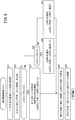
- FIG. 4 is a schematic block diagram of a charging system provided with the electric vehicle which concerns on one Embodiment of this invention. It is a top view which emphasizes and shows a part of the said charging system in the said embodiment. It is a front view which emphasizes and shows a part of the said charging system in the said embodiment. It is an external view which shows roughly a part of external power feeder in the said embodiment. 4 is a flowchart of energization arm control in the embodiment. 4 is a flowchart of power reception control in the electric vehicle in the embodiment. It is a figure which shows an example of the voltage between terminals of a battery, and input-output current at the time of performing the flowchart of FIG. It is a flowchart (details of S13 of FIG.
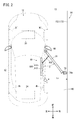
- FIG. 1 is a schematic configuration diagram of a charging system 10 including an electric vehicle 12 according to an embodiment of the present invention.
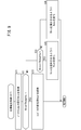
- FIG. 2 is a plan view showing a part of the charging system 10 with emphasis.
- FIG. 3 is a front view showing a part of the charging system 10 with emphasis.
- charging system 10 includes an external power feeding device 14 (hereinafter also referred to as “power feeding device 14”) in addition to electric vehicle 12 (hereinafter also referred to as “vehicle 12”).
- power feeding device 14 hereinafter also referred to as “power feeding device 14”
- vehicle 12 electric vehicle 12
- the directions in FIGS. 2 and 3 (“front”, “back”, “left”, “right”, “up” and “down”) are all based on the vehicle 12 (the same applies to FIG. 4). .)
- electric power is supplied from the power supply device 14 to the vehicle 12, and the traveling battery 24 (FIG. 1) of the vehicle 12 is charged. Conversely, power may be supplied from the vehicle 12 to an external device (such as the power feeding device 14).
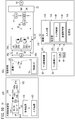
- FIGS. 1 to 3 the vehicle 12 is energized with a travel motor 20 (hereinafter also referred to as “motor 20”), an inverter 22, a travel battery 24 (hereinafter also referred to as “battery 24”). Arm 26, DC / DC converter 28, capacitors 30, 32, voltage sensors 34, 36, 38, 40, current sensors 42, 44, SOC sensor 46, arm deployment mechanism 48 (hereinafter “deployment mechanism 48”). And an arm deployment switch 50, and an energization electronic control device 52 (hereinafter referred to as “energization ECU 52” or “ECU 52”).
- the vehicle 12 travels on a trackless track.
- the electric vehicle 12 can freely change the track, unlike a vehicle that travels on a track such as a railway vehicle.
- the motor 20 is a three-phase AC brushless type, and generates the driving force F [N] (or torque [N ⁇ m]) of the vehicle 12 based on the electric power supplied from the battery 24 via the inverter 22. Further, the motor 20 charges the battery 24 by outputting power (regenerative power Preg) [W] generated by performing regeneration to the battery 24.
- the regenerative power Preg may be output to a step-down converter, a low voltage battery, and an auxiliary machine (not shown).
- the inverter 22 has a three-phase full-bridge configuration, converts the direct current from the battery 24 into a three-phase alternating current and supplies it to the motor 20, while supplying the direct current after the alternating current / direct current conversion accompanying the regenerative operation to the battery 24. Etc.
- the battery 24 is a power storage device (energy storage) including a plurality of battery cells.
- a lithium ion secondary battery, a nickel hydrogen battery, or the like can be used.
- a power storage device such as a capacitor can be used instead of or in addition to the battery 24.
- a DC / DC converter (not shown) may be provided between the inverter 22 and the battery 24 to increase or decrease the output voltage of the battery 24 or the output voltage of the motor 20.
- the energization arm 26 (hereinafter also referred to as “arm 26”) is a part (energization unit) that contacts the power supply device 14 when the battery 24 is charged with electric power from the power supply device 14. As shown in FIG. 2, the energizing arm 26 is connected to the vehicle body 62 so that one end (fixed end) of the energizing arm 26 is rotatable about the rotation shaft 60 between the front wheel Wf and the rear wheel Wr. For this reason, the energization arm 26 can be deployed (displaced) toward the vehicle width direction or the side (right side in the present embodiment) of the vehicle 12 when in contact with the power feeding device 14.
- the power receiving unit 72 includes a positive terminal 76p and a negative terminal 76n.
- the positive terminal 76p and the negative terminal 76n are electrically connected to the fixed end side through a conductive member (not shown).
- the positive electrode terminal 76p and the negative electrode terminal 76n of the present embodiment have a roller shape (see FIGS. 2 and 3).
- the contact sensor 74 detects contact between the energization head 70 and the external power feeding device 14 (external power line 170 described later), and includes, for example, a pressure sensor disposed in a part of the energization head 70.
- the contact sensor 74 may be configured as a voltage sensor disposed between the power reception unit 72 and the converter 28.
- the main configuration of the energizing arm 26 for example, the one described in JP 2013-233037 A can be used.
- the DC / DC converter 28 transforms the output voltage of the power feeding device 14 (hereinafter referred to as “output voltage Vs” or “power feeding voltage Vs”). Output to the inverter 22 and the battery 24.
- the converter 28 can transform the output voltage from the battery 24 and supply the voltage to the outside (for example, the external power supply device 14) via the power receiving unit 72.
- the converter 28 of the present embodiment steps down the power supply voltage Vs and outputs it to the vehicle 12 side, and steps up the output voltage of the battery 24 and outputs it to the outside.
- the converter 28 may perform only boosting of the power supply voltage Vs, or may perform boosting and stepping down.
- the converter 28 includes an upper arm 80, a lower arm 82, and a reactor 84.
- the upper arm 80 includes a switching element 86u and a diode 88u arranged in antiparallel thereto.
- the lower arm 82 includes a switching element 86l and a diode 88l disposed in antiparallel thereto.
- power switching elements such as MOSFETs (including SiC (silicon carbide) type MOSFETs) or IGBTs are employed.
- the switching element 86u is switched by a drive signal Su supplied from the ECU 52, and the switching element 86l is switched by a drive signal S1 supplied from the ECU 52.
- the drive signals Su and Sl are PWM (pulse width modulation) signals.
- one switching element 86u and 86l is shown, but each may be constituted by a plurality of switching elements arranged in parallel.
- a plurality of switching elements 86u arranged in parallel and a plurality of switching elements 86l arranged in parallel may be provided.
- one or more of them may be SiC MOSFETs, and the rest may be constituted by IGBTs.
- the diodes 88u and 88l may be composed of a plurality of diodes arranged in parallel.
- Capacitor 30 is arranged between power reception unit 72 of arm 26 and converter 28.
- the capacitor 32 is disposed between the converter 28 and the branch points 90p and 90n.
- the capacitors 30 and 32 for example, temporarily store power from the power supply device 14 to suppress voltage fluctuation.
- the voltage sensor 34 is disposed between the power receiving unit 72 and the DC / DC converter 28, and is a voltage on the primary side (input side) of the DC / DC converter 28 (hereinafter referred to as “converter input voltage Vc1”, “converter primary voltage”). Vc1 ”or“ primary voltage Vc1 ”).
- the voltage sensor 36 is disposed between the DC / DC converter 28 and the branch points 90p and 90n, and is a secondary side (output side) voltage of the DC / DC converter 28 (hereinafter referred to as “converter output voltage Vc2”, “converter 2”). Next voltage Vc2 "or" secondary voltage Vc2 ”) is detected.
- the voltage sensor 38 is disposed between the branch points 90p and 90n and the battery 24, and the input / output voltage of the battery 24 (hereinafter referred to as “battery input / output voltage Vbio”, “input / output voltage Vbio” or “voltage Vbio”). Is detected.
- the voltage sensor 40 detects a voltage between terminals of the battery 24 (hereinafter referred to as “battery voltage Vbat” or “voltage Vbat”).
- the current sensor 42 is disposed between the DC / DC converter 28 and the branching point 90p, and the current on the secondary side of the DC / DC converter 28 (hereinafter referred to as “converter output current Ic2”, “converter secondary current Ic2” or “ Secondary current Ic2 ").
- the current sensor 44 is disposed between the battery 24 and the branch point 90p, and detects an input / output current of the battery 24 (hereinafter referred to as “battery input / output current Ibio”, “input / output current Ibio” or “current Ibio”). To do.
- the SOC sensor 46 detects the remaining capacity (SOC: State of Charge) of the battery 24 and outputs it to the ECU 52.
- the arm deployment mechanism 48 deploys the arm 26, and includes a slider unit 100 and a damper unit 102 as shown in FIG.
- the slider unit 100 includes a slider 110 and a slider support portion 112.
- the slider 110 can slide with respect to the slider support portion 112 based on a command from the ECU 52.
- the slider 110 is, for example, an electromagnetic or pneumatic linear actuator.
- the damper unit 102 has one end (first end) rotatably connected to the slider 110 and the other end (second end) rotatably connected to the arm 26.
- first end When the arm 26 is deployed, the slider 110 is displaced to the front side of the vehicle 12 and the first end of the damper unit 102 is displaced forward.
- the slider 110 When the arm 26 is housed, the slider 110 is displaced rearward of the vehicle 12 and the first end of the damper unit 102 is displaced rearward.
- the arm deployment switch 50 (hereinafter also referred to as “switch 50”) instructs deployment of the arm 26 by a user operation.
- the switch 50 is formed on a part of a steering wheel (not shown), for example. When the switch 50 is on, the arm 26 is deployed via the deployment mechanism 48, and when the switch 50 is off, the arm 26 is stored via the deployment mechanism 48.
- the ECU 52 receives or controls input from each part of the vehicle 12 via the vehicle-side communication line 120 (FIG. 1), and includes an input / output unit 130, a calculation unit 132, and a storage unit 134.
- the calculation unit 132 of the ECU 52 includes an arm control unit 140 and an energization control unit 142.
- the arm control unit 140 controls the energizing arm 26 via the arm deployment mechanism 48.
- the energization control unit 142 controls charging to the battery 24 or feeding from the battery 24.
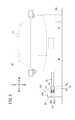
- FIG. 4 is an external view schematically showing a part of the external power supply device 14.
- the power supply device 14 includes a DC power supply 150, a contact power supply unit 152, a DC / DC converter 154 (hereinafter also referred to as “converter 154” or “external converter 154”), a diode 156, a voltage.
- a sensor 158, an input device 160, and a control device 162 are included.
- the DC power supply 150, the converter 154, the diode 156, the voltage sensor 158, the input device 160, and the control device 162 are also referred to as a voltage application unit 164.
- the voltage application unit 164 is a part that applies a voltage to the contact power feeding unit 152.
- DC power supply 150 DC power supply 150 (hereinafter also referred to as “power supply 150”) supplies electric power to vehicle 12.
- the power supply 150 of the present embodiment is configured by connecting a plurality of batteries in series, for example.
- the power source 150 may be configured as a single battery.
- the power source 150 can be configured by a combination (not shown) of an AC commercial power source and an AC / DC converter.
- the contact power supply unit 152 (hereinafter also referred to as “power supply unit 152”) is a part that contacts the arm 26 of the vehicle 12 and supplies power from the power source 150 to the vehicle 12 side. As shown in FIGS. 1 to 4, the contact power feeding unit 152 of the present embodiment includes an external power line 170 (hereinafter also referred to as “power line 170”), a power line holding unit 172, and a plurality of columns 174.
- the external power line 170 includes a positive terminal 180p and a negative terminal 180n. As shown in FIGS. 3 and 4, the positive terminal 180 p and the negative terminal 180 n are formed in a groove 182 formed in the power line holding part 172. For this reason, the external power line 170 is configured as an overhead line disposed above the travel path 190 (FIGS. 2 and 3). Further, as shown in FIG. 2, the positive terminal 180 p and the negative terminal 180 n are disposed along the traveling path 190 of the vehicle 12 on the side of the traveling path 190. In particular, the positive electrode terminal 180p and the negative electrode terminal 180n of the present embodiment are arranged linearly. The length (full length) of the positive electrode terminal 180p and the negative electrode terminal 180n in the traveling direction of the vehicle 12 can be any value in the range of 20 to 300 m, for example.
- the power line holding unit 172 holds the external power line 170 in the groove 182.
- the support column 174 is provided vertically on the side of the travel path 190 and supports the external power line 170 and the power line holding unit 172.
- Converter 154 transforms the input voltage (power supply voltage Vcc) from power supply 150 and outputs it to external power line 170.
- the converter 154 is, for example, a buck-boost converter. Alternatively, depending on the power supply voltage Vcc, the converter 154 can be a step-up or step-down converter.
- the control device 162 controls the transformation rate of the converter 154. That is, the power supply voltage Vs is controlled by transforming the power supply voltage Vcc by adjusting the duty ratio of the drive signal Sd to the converter 154.
- the power supply voltage Vcc of this embodiment is relatively high, and the converter 154 steps down the power supply voltage Vcc to obtain the power supply voltage Vs.
- converter 154 may perform only boosting of power supply voltage Vcc, or may perform boosting and stepping down. After the power supply voltage Vs reaches the target value, the control device 162 keeps the power supply voltage Vs constant.
- the diode 156 is disposed between the converter 154 and the positive terminal 180p, and prevents current from flowing from the vehicle 12 side to the power feeding device 14 side.
- the voltage sensor 158 is arranged on the secondary side (output side) of the DC / DC converter 154, detects the output voltage Vs of the converter 154, and outputs it to the control device 162.
- the input device 160 is for inputting a command from the administrator of the power supply device 14 to the control device 162.
- the input device 160 can be configured by input means such as a plurality of operation buttons and a keyboard, for example.
- Control device 162 The control device 162 controls the entire power feeding device 14 and mainly controls the external converter 154 in this embodiment.
- the energization arm control is control of the energization arm 26 before, during and after the battery 24 is charged, and is executed by the arm control unit 140 of the energization ECU 52.
- the charging control is control for charging the battery 24 of the vehicle 12.
- the charge control includes power supply control executed by the control device 162 of the power supply device 14 and power reception control executed by the power supply control unit 142 of the ECU 52 of the vehicle 12.
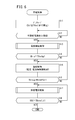
- FIG. 5 is a flowchart of energization arm control in the present embodiment.
- the ECU 52 determines whether or not a deployment start condition for the energization arm 26 is satisfied.
- An example of the deployment start condition is that the deployment switch 50 is turned on.
- the deployment start condition may be that the distance (traveling direction distance) between the vehicle 12 and the contact power feeding unit 152 in the traveling direction of the vehicle 12 is equal to or less than a predetermined threshold (distance threshold).
- a predetermined threshold for example, a vehicle 12 is provided with a current position detection device (for example, a navigation device) (not shown) and a map database that stores position information of the power feeding device 14 (contact power feeding unit 152). deep. Then, the travel direction distance can be calculated as the distance between the current position of the vehicle 12 and the position of the contact power feeding unit 152.
- step S2 If the deployment start condition is not satisfied (S1: NO), the current process is terminated, and the process starts again from step S1 after a predetermined period. If the expansion start condition is satisfied (S1: YES), the process proceeds to step S2.
- step S2 the ECU 52 executes a deployment process for deploying the energizing arm 26 in the stored state.
- the energizing arm 26 is displaced to the position where it protrudes most from the vehicle body 62 of the vehicle 12.
- the driver adjusts the distance Ls (FIG. 2) between the vehicle 12 and the contact power feeding unit 152 by steering, so that the arm 26 approaches the external power line 170.
- step S3 the ECU 52 determines whether or not a condition for ending the deployment of the energizing arm 26 is satisfied.
- the expansion end condition for example, the expansion switch 50 can be turned off.
- the completion of charging of the battery 24 may be set as the deployment end condition. Completion of charging can be determined by the SOC reaching a predetermined threshold (SOC threshold) or the battery voltage Vbat reaching a predetermined threshold (battery voltage threshold).
- SOC threshold a predetermined threshold
- Vbat battery voltage threshold
- a communication device for near field communication is provided in each of the vehicle 12 and the power feeding device 14, and after communication is established between the two communication devices, it is determined that the deployment end condition is satisfied when communication is interrupted. Is also possible.
- step S3 is repeated.
- step S4 the ECU 52 executes a storing process for storing the energizing arm 26 in the expanded state.
- the process starts again from step S1 after a predetermined period has elapsed.
- the control device 162 of the external power supply device 14 sets the external power line 170 in a power supply enabled state based on a command from the administrator input via the input device 160. Specifically, control device 162 intermittently or continuously outputs drive signal Sd (FIG. 1) to a switching element (not shown) of external converter 154 to connect power supply 150 and power line 170. As a result, the power line 170 is in a power feedable state. When the power reception unit 72 of the arm 26 comes into contact with the power line 170, power is supplied from the power supply device 14 to the vehicle 12 through the power line 170.
- FIG. 6 is a flowchart of power reception control in the vehicle 12 in the present embodiment.
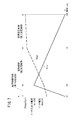
- FIG. 7 is a diagram showing an example of the voltage Vbat between terminals of the battery 24 and the input / output current Ibio when the flowchart of FIG. 6 is executed.
- the control in FIG. 6 is performed when the arm 26 is deployed.
- the ECU 52 starts power reception control when the deployment switch 50 is pressed.
- the ECU 52 performs precharge for boosting the primary voltage Vc1 of the converter 28 to a threshold value (primary voltage threshold value THvc1). Specifically, ECU 52 turns on switching element 86l with switching element 86u turned off, and accumulates electric power from battery 24 in reactor 84. Thereafter, with the switching element 86l turned off, the switching element 86u is turned on to charge the capacitor 30 to increase the primary voltage Vc1.
- a threshold value primary voltage threshold value THvc1
- step S ⁇ b> 12 the ECU 52 determines whether or not the power receiving unit 72 of the arm 26 is in contact with the power feeding unit 152 of the power feeding device 14. This determination is made based on the output of the contact sensor 74.
- step S12 is repeated.
- the process proceeds to step S13.
- step S13 the ECU 52 executes current limit control for limiting the input / output current Ibio (in particular, the input current here) to the battery 24 (time points t1 to t2 in FIG. 7).
- the current limit control will be described later with reference to FIG.
- step S14 the ECU 52 determines whether or not the battery input / output voltage Vbio (in particular, the input voltage (charging voltage) here) is equal to or higher than a threshold (hereinafter referred to as “first charging voltage threshold THvchg1” or “first threshold THvchg1”). Determine whether.
- the threshold value THvchg1 is, for example, such that the voltage difference between the output voltage Vs from the power supply device 14 and the voltage on the vehicle 12 side (primary voltage Vc1) is sufficient to reduce the inrush current from the power supply device 14 to the vehicle 12. It is a threshold value for determining whether or not it is small.
- the threshold value THvchg1 is set to a value lower than the full charge voltage THvbatfull of the battery 24.
- the process returns to step S13 to continue the current limit control.
- the voltage Vbio is equal to or higher than the threshold value THvchg1 (S14: YES)
- the current limit control is terminated and the process proceeds to step S15.
- the determination in step S14 may be a comparison between the battery input / output current Ibio and its threshold (input current threshold THichg1) instead of the comparison between the battery input / output voltage Vbio and the threshold THvchg1.
- the current threshold THichg1 is a threshold for ensuring that the current (current Ibio or current Ic2) input to the battery 24 does not become an inrush current.
- step S15 the ECU 52 stops the transformation by the converter 28 and executes direct connection control for directly supplying the electric power from the power feeding device 14 to the battery 24 or the like (time points t2 to t3 in FIG. 7).
- ECU 52 continuously outputs drive signal Su to switching element 86u of converter 28 (that is, duty ratio 100%).
- the direct connection control is a control (voltage / current unlimited control) in which the combination of the battery input / output voltage Vbio and the battery input / output current Ibio (or the combination of the output voltage Vc2 and the output current Ic2 of the converter 28) is not directly controlled. is there.
- the output voltage Vs of the power feeding unit 152 is applied to the battery 24 without transformation in the converter 28.
- the battery voltage Vbat gradually increases while the battery input / output current Ibio decreases (see time points t2 to t3 in FIG. 7).
- step S16 the ECU 52 determines whether or not the voltage Vbio is equal to or higher than the full charge voltage THvbatfull of the battery 24.
- the process returns to step S15 and the direct connection control is continued.
- the direct connection process is terminated and the process proceeds to step S17.
- step S17 the ECU 52 executes target voltage control for matching the battery input / output voltage Vbio with a target value (hereinafter referred to as “target voltage Vbiotar”) (time points t3 to t4 in FIG. 7).
- target voltage Vbiotar is set to the full charge voltage THvbatfull of the battery 24. That is, ECU 52 sets the duty of converter 28 so that voltage Vbio after transformation by converter 28 becomes full charge voltage THvbatfull.
- the battery voltage Vbat gradually rises toward the full charge voltage THvbatfull, while the battery input / output current Ibio decreases (see time points t3 to t4 in FIG. 7).
- step S18 the ECU 52 determines whether or not the SOC of the battery 24 is equal to or greater than a threshold (hereinafter referred to as “full charge threshold THsocfull” or “threshold THsocfull”).
- the threshold value THsocfull is an SOC threshold value indicating that the battery 24 is fully charged.
- the voltage Vbio and the full charge voltage THvbatfull may be compared instead of comparing the SOC and the threshold value.
- the process returns to step S17, and the target voltage control is continued. If the SOC is equal to or greater than the threshold THsocfull (S18: YES), the ECU 52 ends the target voltage control and ends the current process.
- FIG. 8 is a flowchart of the current limiting control (details of S13 in FIG. 6).
- the execution time of the current limit control in this embodiment is significantly shorter than the execution time of the direct connection control. Thereby, it is possible to realize ultra-high speed charging in the vehicle 12.
- the time relationship between the current limit control and the direct connection control will be described in detail later. In the following, “(current)” is added to the value in the current calculation cycle, and “(previous)” is added to the value in the previous calculation cycle.
- the ECU 52 acquires the battery input / output current Ibio (this time)).
- step S22 the ECU 52 calculates a current difference ⁇ Ibio.
- the current difference ⁇ Ibio is a difference between the battery input / output current Ibio (current) and the battery input / output current Ibio (previous).
- step S23 the ECU 52 determines whether or not the current difference ⁇ Ibio is below a threshold value (hereinafter, also referred to as “current difference threshold value TH ⁇ ibio” or “threshold value TH ⁇ ibio”).
- the threshold value TH ⁇ ibio is a threshold value for ensuring that the current (current Ibio or current Ic2) input to the battery 24 does not become an inrush current.
- the threshold value TH ⁇ ibio is set to a value corresponding to 10 to 100 times (for example, 60 times or more) of the discharge capacity Wb [Ah] as the specification of the battery 24.
- the threshold value TH ⁇ ibio is set to a value that realizes 20 to 200 [Ah].
- the threshold value TH ⁇ ibio is set depending on the calculation cycle in which the flowchart of FIG. 8 is performed.
- step S24 the ECU 52 increases the added value ⁇ DUTu of the duty DUTu of the upper arm 80.
- the positive fixed value ⁇ is added to the added value ⁇ DUTu (previous) of the duty DUTu to obtain the added value ⁇ DUTu (current).
- step S28 the ECU 52 calculates the duty DUTu (current) by adding the added value ⁇ DUTu (current) to the duty DUTu (previous).
- step S25 the ECU 52 determines whether or not the current difference ⁇ Ibio exceeds the threshold value TH ⁇ ibio.
- the threshold value in step S25 may be another value larger than the threshold value in step S23.
- the ECU 52 decreases the added value ⁇ DUTu of the duty DUTu of the upper arm 80. That is, the positive fixed value ⁇ is subtracted from the added value ⁇ DUTu (previous) of the duty DUTu to obtain the added value ⁇ DUTu (current).
- step S27 the ECU 52 maintains the added value ⁇ DUTu. That is, the added value ⁇ DUTu (previous) is directly used as the added value ⁇ DUTu (current).
- step S28 the ECU 52 calculates the duty DUTu (current) by adding the addition value ⁇ DUTu (current) to the duty DUTu (previous).
- FIG. 9 is a flowchart of the target voltage control (details of S17 in FIG. 6).
- step S31 the ECU 52 acquires the battery input / output voltage Vbio in the current calculation cycle (control cycle) from the voltage sensor 38.
- step S32 the ECU 52 determines whether or not the voltage Vbio is equal to the full charge voltage THvbatfull of the battery 24.
- step S33 ECU 52 maintains conversion rate Rcon of converter 28.
- the process proceeds to step S34.
- step S34 the ECU 52 determines whether or not the voltage Vbio is lower than the full charge voltage THvbatfull.
- voltage Vbio is lower than full charge voltage THvbatfull (S34: YES)
- step S35 ECU 52 changes conversion ratio Rcon of converter 28 so as to increase input / output voltage Vbio. For example, in the case of step-down, increasing the duty DUTu of the switching element 86u of the upper arm 80 decreases the step-down rate, and decreasing the duty DUTu increases the step-down rate.
- step S36 the ECU 52 changes the transformation rate Rcon of the converter 28 so as to decrease the input / output voltage Vbio.
- the vehicle 12 according to the present embodiment travels on a trackless. For this reason, compared with the vehicle which drive
- the travel path 190 is composed of a plurality of lanes and a plurality of electric vehicles are traveling on the same travel path 190, the tendency becomes stronger. In particular, this tendency becomes more prominent in scenes where automobile races are held.
- the energization head 70 can be contacted and separated at any position of the external power line 170.
- the execution time of the current limit control (first charge control) is shortened as much as possible, and the execution time of the direct connection control (second charge control) is extended as much as possible.
- the time ratio relative to the execution time of the direct connection control is also reduced by shortening the execution time (absolute value) of the current limiting control.
- the discharge capacity of the DC power supply 150 is first made relatively high on the power supply device 14 side.
- the power supply voltage Vs is equal to or equal to the full charge voltage THvbatfull of the battery 24 (a margin). Set to a value that takes into account voltage drop, etc.).
- the total length Llp (length) of the external power line 170 is such that the SOC of the battery 24 is a predetermined value (for example, a fixed value consisting of any value of 0 to 30%) and the vehicle 12 is at an assumed speed (for example, 20 Current limit control when power is applied from the front end to the back end of the external power line 170 in a state (or any value of ⁇ 150 km / h) (or in an assumed speed range) It is set to be performed in a range shorter than half of the length of 170.
- a predetermined value for example, a fixed value consisting of any value of 0 to 30%
- the vehicle 12 is at an assumed speed (for example, 20 Current limit control when power is applied from the front end to the back end of the external power line 170 in a state (or any value of ⁇ 150 km / h) (or in an assumed speed range) It is set to be performed in a range shorter than half of the length of 170.
- the current limit control is completed with a contact length of 1 to 10 m
- the direct connection control is completed with a contact length of 19 to 150 m.
- the current limit control and the direct connection control are completed without contacting the power line 170 over the entire length Llp of the external power line 170.
- the current limit control and the direct connection control can be completed by contacting with half or less of the total length Llp.
- the threshold value TH ⁇ bio of the current difference ⁇ Ibio in the current limit control (S13 in FIG. 6, FIG. 8) (the current Ibio of (Increase rate) (S23, S25 in FIG. 8) is set to a value corresponding to 10 to 100 times (for example, 60 times or more) of the discharge capacity Wb of the battery 24.
- a switching element for example, a SiC MOSFET having a high current passing speed as the switching elements 86u and 86l (at least the switching element 86u).
- direct connection control is used as control following current limit control (however, other control can be used as will be described later).
- current limit control (however, other control can be used as will be described later).
- direct connection control for performing power feeding without voltage transformation is performed for a longer time than the current limit control (S15 in FIG. 6, FIG. 7). Therefore, charging in an extremely short time is possible by combining the current limit control and the direct connection control.
- the external power line 170 and the energizing arm 26 are brought into contact while moving the contact in a control environment ranging from current limit control to direct connection control, so that heat generation at the contact is not concentrated in one place. This prevents welding of the external power line 170 and the energizing arm 26 or damage of the electric circuit on the external power line 170 side or the energizing arm 26 side even if a high current is energized in the direct connection control that is longer than the current limiting control. It becomes possible.
- the contact position to the external power line 170 and the external power line 170 are determined by the driver's intention, which is a problem when traveling on a trackless track.
- Battery 24 power storage device reliably even in a situation in which the charging time is unpredictable due to a change in the position of separation from the vehicle and traveling at a high speed in the power feeding section defined by the external power line 170 Can be charged.
- the ECU 52 causes the battery input / output voltage Vbio (or the output voltage Vc2 of the converter 28 (voltage converter)) to reach the full charge voltage THvbatfull of the battery 24 in the direct connection control (second charge control). Then (S16 in FIG. 6: YES), target voltage control (third charge control) for operating the converter 28 so as to maintain the voltage Vbio at the full charge voltage THvbatfull is executed (S17 in FIG. 6, FIG. 9). Thereby, the battery 24 can be fully charged more reliably.
- a roller-shaped positive electrode terminal 76p and a negative electrode terminal 76n that are in contact with the external power line 170 are formed at the tip of the energization arm 26 (FIGS. 2 and 3).
- the electric vehicle 12 includes an arm deployment mechanism 48 (arm displacement mechanism) that causes the energizing arm 26 to protrude on the side of the vehicle body 62 during traveling (FIG. 2).
- the external power line 170 can be disposed on the side of the traveling path 190, so that the external power line 170 can be installed at a low cost. That is, since the external power line 170 can be provided at a lower position as compared with the case where the external power line 170 is disposed above the vehicle body 62, the equipment for supporting the external power line 170 can be simplified. it can.
- the external power line 170 is disposed below the vehicle body 62, it is necessary to embed the external power line 170 in the travel path 190. However, when the external power line 170 is disposed on the side of the travel path 190, the external power line 170 travels. There is no need to embed in the path 190. For this reason, the external power line 170 can be easily arranged.
- Vehicle 12 [2A-1. Types of vehicles 12]
- the vehicle 12 that is an automobile is described (FIG. 2).
- the present invention can be applied to vehicles other than automobiles.
- the vehicle 12 can be any one of a motorcycle, an automatic tricycle, and an automatic six-wheeled vehicle.
- the present invention can be applied to a moving object (for example, a ship) other than the vehicle 12.
- the vehicle 12 is assumed to be a so-called battery vehicle having only the traveling motor 20 as a drive source (FIG. 1).
- the vehicle 12 may be an electric vehicle other than an electric vehicle.
- the vehicle 12 may be a hybrid vehicle or a fuel cell vehicle.
- FIG. 10 is a schematic configuration diagram of a charging system 10A including an electric vehicle 12a (hereinafter also referred to as “vehicle 12a”) according to a modification of the present invention.
- vehicle 12a an electric vehicle 12a (hereinafter also referred to as “vehicle 12a”) according to a modification of the present invention.
- the converter 28 of the vehicle 12 according to the above embodiment is disposed between the power reception unit 72 and the branch points 90p and 90n (FIG. 1).
- the converter 28a of the vehicle 12a according to the modification is disposed between the battery 24 and the branch points 90p and 90n (FIG. 10).
- the arm 26 is disposed on the right side of the vehicle body 62 so as to be deployable (FIGS. 2 and 3).
- the arm 26 may be arranged on the left side, upper side, or lower side of the vehicle body 62 without being limited to this. Note that when the arrangement of the arm 26 is changed, the arrangement of the external power line 170 of the power feeding device 14 also needs to be changed.
- External power supply device 14 [2B-1. External power line 170]
- the external power lines 170 are arranged in a straight line (see FIG. 2). However, for example, if attention is paid to power reception control (FIG. 6) in the vehicle 12, the vehicle 12 may be arranged along a curved road.
- the power supply voltage Vs of the external power line 170 is controlled by controlling the external converter 154 by the control device 162.
- the power supply 150 is configured as an assembly in which a plurality of DC power supplies (for example, batteries) are connected in series, the converter 154 and the control device 162 can be omitted.
- the power reception control in the above embodiment includes current limit control, direct connection control (voltage / current unrestricted control), and target voltage control (FIG. 6). However, for example, if attention is paid to the current limit control and the direct connection control, the target voltage control can be omitted.
- the converter output voltage Vc2 can be used in the process using the battery input / output voltage Vbio as a control target (for example, S14 in FIG. 6).
- the converter output current Ic2 can be used in the process using the battery input / output current Ibio as a control target (for example, S22, S23, S25 in FIG. 8).
- the direct connection control is used as the control (second charge control) following the current limiting control (S15 in FIG. 6).
- the present invention is not limited to this.
- a target value (target power Pbiotar) of power supplied to the battery 24 hereinafter referred to as “supply power Pbio”, “battery input / output power Pbio” or “power Pbio” is set, and the supply power Pbio is the target power Pbiotar. It is also possible to perform target power control for controlling to match.
- FIG. 11 is a flowchart of target power control.
- the target power control is used instead of the direct connection control (S15 in FIG. 6).
- step S41 the ECU 52 acquires the battery input / output voltage Vbio and the battery input / output current Ibio.
- step S42 the ECU 52 multiplies the voltage Vbio and the current Ibio to calculate the battery input / output power Pbio.
- step S43 the ECU 52 determines whether or not the electric power Pbio is equal to a threshold value (hereinafter referred to as “threshold value THpbio”).
- the threshold value THpbio can be set to a value at which the converter 28 can perform voltage conversion with relatively high efficiency, for example.
- ECU 52 maintains conversion rate Rcon of converter 28 in step S44. If the power Pbio is not equal to the threshold value THpbio (S43: NO), the process proceeds to step S45. Note that the determination in step S43 can use a certain range including the threshold THpbio instead of using the threshold THpbio (single value).
- step S45 the ECU 52 determines whether or not the electric power Pbio is lower than the threshold value THpbio.
- ECU 52 changes conversion ratio Rcon of converter 28 so as to increase input / output electric power Pbio (and input / output voltage Vbio).
- step S47 the ECU 52 changes the transformation ratio Rcon of the converter 28 so as to decrease the input / output power Pbio (and the input / output voltage Vbio).
- the present invention is applied when power is supplied from the power supply device 14 to the vehicle 12 with direct current.
- the present invention can also be applied to the case where power is supplied from the power supply device 14 to the vehicle 12 with alternating current.
- charging is performed while moving the contact point of the vehicle 12 by moving the energizing arm 26 (the energizing unit) of the vehicle 12 with respect to the external power line 170 (the feeding unit or the feeding line) of the power feeding device 14.
- the external power line 170 was in a stationary state, and charging was performed while the arm 26 was in a moving state.
- the present invention is not limited to this.
- a configuration in which the power feeding unit of the power feeding device 14 is displaced with respect to the power feeding unit of the vehicle 12 is also possible.
- an energization section displacement mechanism that displaces the energization section (for example, the external power line 170) of the power feeding device 14 is provided with respect to the stationary energization section.
- the displacement of the energization unit can be, for example, a linear unidirectional movement or a reciprocating movement.
- the energization part is formed in an arc shape or an annular shape, the energization part can be rotated.
Abstract
Description
1A.構成
[1A-1.全体構成]
図1は、本発明の一実施形態に係る電動車両12を備える充電システム10の概略構成図である。図2は、充電システム10の一部を強調して示す平面図である。図3は、充電システム10の一部を強調して示す正面図である。図1~図3に示すように、充電システム10は、電動車両12(以下「車両12」ともいう。)に加え、外部給電装置14(以下「給電装置14」ともいう。)を含む。図2及び図3における方向(「前」、「後」、「左」、「右」、「上」及び「下」)は、いずれも車両12を基準とした方向である(図4も同様である。)。
(1A-2-1.車両12の全体構成)
図1~図3に示すように、車両12は、走行モータ20(以下「モータ20」ともいう。)と、インバータ22と、走行用バッテリ24(以下「バッテリ24」ともいう。)と、通電アーム26と、DC/DCコンバータ28と、コンデンサ30、32と、電圧センサ34、36、38、40と、電流センサ42、44と、SOCセンサ46と、アーム展開機構48(以下「展開機構48」ともいう。)と、アーム展開スイッチ50と、通電電子制御装置52(以下「通電ECU52」又は「ECU52」という。)とを有する。
モータ20は、3相交流ブラシレス式であり、インバータ22を介してバッテリ24から供給される電力に基づいて車両12の駆動力F[N](又はトルク[N・m])を生成する。また、モータ20は、回生を行うことで生成した電力(回生電力Preg)[W]をバッテリ24に出力することでバッテリ24の充電を行う。回生電力Pregは、図示しない降圧型コンバータ、低電圧バッテリ及び補機に出力してもよい。
インバータ22は、3相フルブリッジ型の構成とされて、バッテリ24からの直流を3相の交流に変換してモータ20に供給する一方、回生動作に伴う交流/直流変換後の直流をバッテリ24等に供給する。
バッテリ24は、複数のバッテリセルを含む蓄電装置(エネルギストレージ)であり、例えば、リチウムイオン2次電池、ニッケル水素電池等を利用することができる。或いは、バッテリ24の代わりに又はバッテリ24に加えて、キャパシタ等の蓄電装置を用いることも可能である。なお、インバータ22とバッテリ24との間に図示しないDC/DCコンバータを設け、バッテリ24の出力電圧又はモータ20の出力電圧を昇圧又は降圧してもよい。
通電アーム26(以下「アーム26」ともいう。)は、給電装置14からの電力によりバッテリ24を充電する際に給電装置14と接触する部位(通電部)である。図2に示すように、通電アーム26は、前輪Wf及び後輪Wrの間において、その一端(固定端)が回転軸60を中心として回動可能に車体62に連結されている。このため、通電アーム26は、給電装置14との接触時に車両12の車幅方向又は側方(本実施形態では右側)に向かって展開(変位)可能である。
DC/DCコンバータ28(以下「コンバータ28」又は「車両側コンバータ28」ともいう。)は、給電装置14の出力電圧(以下「出力電圧Vs」又は「給電電圧Vs」という。)を変圧してインバータ22及びバッテリ24に出力する。加えて、コンバータ28は、バッテリ24からの出力電圧を変圧して受電部72を介して外部(例えば、外部給電装置14)に供給することができる。
コンデンサ30は、アーム26の受電部72とコンバータ28との間に配置される。コンデンサ32は、コンバータ28と分岐点90p、90nとの間に配置される。コンデンサ30、32は、例えば、給電装置14からの電力を一時的に蓄えて電圧変動を抑制する。
電圧センサ34は、受電部72とDC/DCコンバータ28との間に配置され、DC/DCコンバータ28の1次側(入力側)の電圧(以下「コンバータ入力電圧Vc1」、「コンバータ1次電圧Vc1」又は「1次電圧Vc1」という。)を検出する。電圧センサ36は、DC/DCコンバータ28と分岐点90p、90nとの間に配置され、DC/DCコンバータ28の2次側(出力側)の電圧(以下「コンバータ出力電圧Vc2」、「コンバータ2次電圧Vc2」又は「2次電圧Vc2」という。)を検出する。
電流センサ42は、DC/DCコンバータ28と分岐点90pとの間に配置され、DC/DCコンバータ28の2次側の電流(以下「コンバータ出力電流Ic2」、「コンバータ2次電流Ic2」又は「2次電流Ic2」という。)を検出する。電流センサ44は、バッテリ24と分岐点90pとの間に配置され、バッテリ24の入出力電流(以下「バッテリ入出力電流Ibio」、「入出力電流Ibio」又は「電流Ibio」という。)を検出する。
SOCセンサ46は、バッテリ24の残容量(SOC:State of Charge)を検出してECU52に出力する。
アーム展開機構48は、アーム26を展開させるものであり、図2に示すように、スライダユニット100と、ダンパユニット102とを有する。スライダユニット100は、スライダ110及びスライダ支持部112を含む。スライダ110は、ECU52からの指令に基づき、スライダ支持部112に対して摺動可能である。スライダ110は、例えば、電磁式又は空気圧式のリニアアクチュエータである。
ECU52は、車両側通信線120(図1)を介して車両12の各部からの入力を受け付け又は各部を制御するものであり、入出力部130、演算部132及び記憶部134を含む。本実施形態において、ECU52の演算部132は、アーム制御部140及び通電制御部142を有する。アーム制御部140は、アーム展開機構48を介して通電アーム26を制御する。通電制御部142は、バッテリ24への充電又はバッテリ24からの給電を制御する。
図4は、外部給電装置14の一部を概略的に示す外観図である。図1~図4に示すように、給電装置14は、直流電源150、接触給電部152、DC/DCコンバータ154(以下「コンバータ154」又は「外部コンバータ154」ともいう。)、ダイオード156、電圧センサ158、入力装置160及び制御装置162を有する。以下では、直流電源150、コンバータ154、ダイオード156、電圧センサ158、入力装置160及び制御装置162を電圧印加部164ともいう。電圧印加部164は、接触給電部152に対して電圧を印加する部位である。
直流電源150(以下「電源150」ともいう。)は、車両12に対して電力を供給する。本実施形態の電源150は、例えば、複数のバッテリが直列に接続されて構成される。或いは、電源150は、単一のバッテリとして構成されてもよい。或いは、電源150は、交流の商用電源とAC/DCコンバータとの組合せ(図示せず)により構成することも可能である。
(1A-3-2-1.接触給電部152の全体)
接触給電部152(以下「給電部152」ともいう。)は、車両12のアーム26と接触して電源150からの電力を車両12側に供給する部位である。図1~図4に示すように、本実施形態の接触給電部152は、外部電力線170(以下「電力線170」ともいう。)と、電力線保持部172と、複数の支柱174とを含む。
外部電力線170は、正極端子180p及び負極端子180nを備える。図3及び図4に示すように、正極端子180p及び負極端子180nは、電力線保持部172に形成された溝部182内に形成される。このため、外部電力線170は、走行路190(図2及び図3)の上方に配置された架線として構成される。また、図2に示すように、正極端子180p及び負極端子180nは、車両12の走行路190に沿って走行路190の側方に配置されている。特に本実施形態の正極端子180p及び負極端子180nは、直線状に配置される。車両12の進行方向における正極端子180p及び負極端子180nの長さ(全長)は、例えば、20~300mの範囲におけるいずれかの値とすることができる。
上記のように、電力線保持部172は、その溝部182において外部電力線170を保持する。支柱174は、走行路190の側方において垂直に設けられ、外部電力線170及び電力線保持部172を支持する。
コンバータ154は、電源150からの入力電圧(電源電圧Vcc)を変圧して外部電力線170に出力する。コンバータ154は、例えば、昇降圧式コンバータである。或いは、電源電圧Vccに依存して、コンバータ154は、昇圧式又は降圧式のコンバータとすることも可能である。
ダイオード156は、コンバータ154と正極端子180pの間に配置され、車両12側から給電装置14側に電流が流れることを防止する。
電圧センサ158は、DC/DCコンバータ154の2次側(出力側)に配置され、コンバータ154の出力電圧Vsを検出して、制御装置162に出力する。
入力装置160は、給電装置14の管理者の指令を制御装置162に入力するためのものである。入力装置160は、例えば、複数の操作ボタン、キーボード等の入力手段により構成することができる。
制御装置162は、給電装置14全体を制御するものであり、本実施形態では、主として外部コンバータ154を制御する。
[1B-1.概要]
次に、給電装置14から車両12に対して電力を供給し、車両12のバッテリ24を充電する際の各種制御について説明する。ここでの制御には、通電アーム制御及び充電制御が含まれる。
図5は、本実施形態における通電アーム制御のフローチャートである。ステップS1において、ECU52は、通電アーム26の展開開始条件が成立したか否かを判定する。当該展開開始条件としては、例えば、展開スイッチ50がオンされたことを挙げることができる。
外部給電装置14の制御装置162は、入力装置160を介して入力された管理者からの指令に基づいて外部電力線170を給電可能状態とする。具体的には、制御装置162は、外部コンバータ154のスイッチング素子(図示せず)に駆動信号Sd(図1)を断続的に又は連続的に出力して電源150と電力線170とを接続する。これにより、電力線170は給電可能状態となる。そして、アーム26の受電部72が電力線170に接触したとき、当該電力線170を介して給電装置14から車両12への給電が行われる。
(1B-4-1.受電制御の全体的な流れ)
図6は、本実施形態における車両12での受電制御のフローチャートである。図7は、図6のフローチャートを実行した場合におけるバッテリ24の端子間電圧Vbat及び入出力電流Ibioの一例を示す図である。図6の制御は、アーム26が展開しているときに行われる。例えば、ECU52は、展開スイッチ50が押されたことを契機として受電制御を開始する。
図8は、電流制限制御のフローチャート(図6のS13の詳細)である。本実施形態における電流制限制御の実行時間は、直結制御の実行時間と比較して大幅に短い。これにより、車両12での超高速充電を実現することが可能となる。電流制限制御と直結制御との時間的関係については後に詳述する。以下では、今回の演算周期における値には「(今回)」を付し、前回の演算周期における値には「(前回)」を付す。
図9は、目標電圧制御のフローチャート(図6のS17の詳細)である。ステップS31において、ECU52は、今回の演算周期(制御周期)におけるバッテリ入出力電圧Vbioを電圧センサ38から取得する。ステップS32において、ECU52は、電圧Vbioが、バッテリ24の満充電電圧THvbatfullと等しいか否かを判定する。電圧Vbioが満充電電圧THvbatfullと等しい場合(S32:YES)、ステップS33において、ECU52は、コンバータ28の変圧率Rconを維持する。電圧Vbioが満充電電圧THvbatfullと等しくない場合(S32:NO)、ステップS34に進む。
以下では、電流制限制御と直結制御との時間的関係について説明する。上記のように、本実施形態における電流制限制御の実行時間は、直結制御の実行時間と比較して大幅に短く、車両12での超高速充電を実現することが可能となる。
本実施形態に係る車両12は、無軌道上を走行するものである。このため、鉄道車両のように軌道上を走行する車両と比較して、外部電力線170との接触開始位置及び接触後の離間位置の自由度が高い。軌道上を走行する車両であれば、外部電力線170との接触開始位置及び接触後の離間位置は、基本的に同じとなる。これに対し、車両12のような無軌道上を走行する電動車両は、接触開始位置及び離間位置を運転者の意思に委ねることが好ましい。走行路190が複数車線から構成され、複数の電動車両が同一の走行路190を走行している場合、その傾向が強くなる。特に、自動車レースが開催されている場面ではさらにその傾向が顕著となる。
電流制限制御の実行時間を極力短くし、直結制御の実行時間を極力長くするため、給電装置14側では、まず直流電源150の放電容量を比較的高くする。加えて、直結制御においてコンバータ28での電力損失(スイッチング損失等)を回避しつつ高効率での充電を行うため、給電電圧Vsをバッテリ24の満充電電圧THvbatfullと等しい値又はこれに余裕分(電圧降下等を考慮した値)に設定する。
電流制限制御の実行時間を極力短くし、直結制御の実行時間を極力長くするため、車両12側では、電流制限制御(図6のS13、図8)における電流差ΔIbioの閾値THΔibio(電流Ibioの増加率)(図8のS23、S25)を、バッテリ24の放電容量Wbの10~100倍(例えば、60倍又はそれ以上)に対応する値に設定する。この際、閾値THΔibioを実現するため、スイッチング素子86u、86l(少なくともスイッチング素子86u)について、電流の通過速度が速いスイッチング素子(例えば、SiC型MOSFET)を用いることが好ましい。
以上のように、本実施形態によれば、通電アーム26(通電部)が外部電力線170(給電部又は給電線)に接触すると、バッテリ24(蓄電装置)への入力電流(入出力電流Ibio)を制御対象とする電流制限制御(第1充電制御)を行う(図6のS13、図8)。これにより、通電開始時の瞬間的なサージ電流を防止して外部電力線170と通電アーム26との溶着又は外部電力線170側若しくは通電アーム26側の電気回路の破損を防ぐことが可能となる。また、電流制限制御の後に、変圧なしでの給電を実行する直結制御(第2充電制御)を電流制限制御よりも長時間行う(図6のS15、図7)。従って、電流制限制御と直結制御を組み合わせることで極短時間での充電が可能になる。
なお、本発明は、上記実施形態に限らず、本明細書の記載内容に基づき、種々の構成を採り得ることはもちろんである。例えば、以下の構成を採用することができる。
[2A-1.車両12の種類]
上記実施形態では、自動四輪車である車両12について説明した(図2)。しかしながら、例えば、車両12での受電制御(図6)に着目すれば、自動四輪車以外の車両にも本発明を適用可能である。例えば、車両12は、自動二輪車、自動三輪車及び自動六輪車のいずれかとすることも可能である。或いは、車両12以外の移動物体(例えば、船舶)に対して本発明を適用することもできる。
上記実施形態では、車両12の電気的な回路構成を図1に示すものとした。しかしながら、例えば、車両12での受電制御(図6)に着目すれば、これに限らない。例えば、車両側コンバータ28の位置を変更することも可能である。
上記実施形態では、車体62の右側方に展開可能にアーム26を配置した(図2及び図3)。しかしながら、例えば、車両12での受電制御(図6)に着目すれば、これに限らず、車体62の左側方又は上側若しくは下側にアーム26を配置してもよい。なお、アーム26の配置を変更した場合、給電装置14の外部電力線170の配置も変更する必要が生じる。
[2B-1.外部電力線170]
上記実施形態では、外部電力線170を直線状に配置した(図2参照)。しかしながら、例えば、車両12での受電制御(図6)に着目すれば、カーブ路に沿って配置してもよい。
上記実施形態では、制御装置162により外部コンバータ154を制御することで外部電力線170の給電電圧Vsを制御した。しかしながら、例えば、複数の直流電源(例えば、バッテリ)が直列に接続された集合体として電源150が構成される場合、コンバータ154及び制御装置162を省略することも可能である。
[2C-1.全般]
上記実施形態における受電制御は、電流制限制御、直結制御(電圧・電流無制限制御)及び目標電圧制御を含んでいた(図6)。しかしながら、例えば、電流制限制御及び直結制御に着目すれば、目標電圧制御を省略することも可能である。
上記実施形態の電流制限制御では、バッテリ入出力電流Ibioの増加率を所定値(閾値THΔibio)以下に抑制する制御を用いた(図8)。しかしながら、例えば、電流Ibio又はその変化を制限する観点からすれば、これに限らない。例えば、定電流制御も可能である。すなわち、ECU52は、電流Ibioの目標値(目標電流Ibiotar)を設定し、電流Ibioが目標電流Ibiotarと一致するようにコンバータ28の変圧率Rconを制御してもよい。
上記実施形態では、電流制限制御に続く制御(第2充電制御)として、直結制御を用いた(図6のS15)。しかしながら、例えば、電圧Vbio及び電流Ibioを直接的には制限しない制御(電圧・電流無制限制御)としての観点からすれば、これに限らない。例えば、バッテリ24に供給される電力(以下「供給電力Pbio」、「バッテリ入出力電力Pbio又は「電力Pbio」という。)の目標値(目標電力Pbiotar)を設定し、供給電力Pbioが目標電力Pbiotarと一致するように制御する目標電力制御を行うことも可能である。
上記実施形態(図1)及び上記変形例(図10)では、給電装置14から車両12への給電のみを行う構成について説明した。しかしながら、これとは反対に、車両12から給電装置14への給電を行う構成に本発明を適用することも可能である。その場合、車両12においてガソリン等により発電機で発電を行うことができるのであれば、走行モータ20に電力を供給するためのバッテリ24又は蓄電装置を設けないことも可能である。
Claims (5)
- 無軌道上を走行する電動車両(12、12a)であって、
前記電動車両(12、12a)は、
走行モータ(20)と、
前記走行モータ(20)に電力を供給する蓄電装置(24)と、
給電部(152)と接触して前記給電部(152)と前記蓄電装置(24)との間を電気的に接続させる通電部(26)と、
前記通電部(26)を介して前記給電部(152)から前記蓄電装置(24)への電力の供給を調整する電圧変換器(28、28a)と、
前記電圧変換器(28、28a)を制御する制御装置(52)と
を備え、
前記制御装置(52)は、
前記給電部(152)から前記蓄電装置(24)への入力電流又は単位時間当たりの前記入力電流の変化量を制限するように前記電圧変換器(28、28a)を制御して前記蓄電装置(24)を充電させる第1充電制御と、
前記電圧変換器(28、28a)の変圧動作を停止させて変圧なしに前記給電部(152)からの電力を前記蓄電装置(24)に充電させる又は前記蓄電装置(24)に供給する電力の目標値である目標電力に基づいて前記電圧変換器(28、28a)を制御して前記蓄電装置(24)に充電させる第2充電制御と
を実行し、
さらに、前記制御装置(52)は、
前記通電部(26)と前記給電部(152)の接点を移動させながら前記第1充電制御及び前記第2充電制御を実行し、
前記通電部(26)が前記給電部(152)に接触すると前記第1充電制御を実行し、
前記第1充電制御の後に、前記第1充電制御よりも長い時間、前記第2充電制御を実行する
ことを特徴とする電動車両(12、12a)。 - 請求項1記載の電動車両(12、12a)において、
前記制御装置(52)は、前記第2充電制御において前記蓄電装置(24)への入力電圧が前記蓄電装置(24)の満充電電圧に到達すると、前記入力電圧を前記満充電電圧に維持するように前記電圧変換器(28、28a)を動作させる第3充電制御を実行する
ことを特徴とする電動車両(12、12a)。 - 請求項1又は2記載の電動車両(12、12a)において、
前記通電部(26)の先端には、前記給電部(152)と接触するローラ形状の端子(76n、76p)が形成される
ことを特徴とする電動車両(12、12a)。 - 請求項1~3のいずれか1項に記載の電動車両(12、12a)において、
前記電動車両(12、12a)は、走行中に前記通電部(26)を車体(62)の側方において突出させるアーム変位機構(48)を備える
ことを特徴とする電動車両(12、12a)。 - 外部給電装置(14)の給電部(152)に対して電動車両(12、12a)の通電部(26)が接触した状態で前記外部給電装置(14)の電力により前記電動車両(12、12a)の蓄電装置(24)を充電する車両給電方法であって、
前記電動車両(12、12a)は、無軌道上を走行するものであり、
前記電動車両(12、12a)では、
前記給電部(152)から前記蓄電装置(24)への入力電流又は単位時間当たりの前記入力電流の変化量を制限するように電圧変換器(28、28a)を制御して前記蓄電装置(24)を充電させる第1充電制御と、
前記電圧変換器(28、28a)の変圧動作を停止させて変圧なしに前記給電部(152)からの電力を前記蓄電装置(24)に充電させる又は前記蓄電装置(24)に供給する電力の目標値である目標電力値に基づいて前記電圧変換器(28、28a)を制御して前記蓄電装置(24)に充電させる第2充電制御と
を実行し、
さらに、前記電動車両(12、12a)では、
前記通電部(26)と前記給電部(152)の接点を移動させながら前記第1充電制御及び前記第2充電制御を実行し、
前記通電部(26)が前記給電部(152)に接触すると前記第1充電制御を実行し、
前記第1充電制御の後に前記第2充電制御を実行し、
前記給電部(152)は、任意の位置で前記通電部(26)と接触開始可能且つ離間可能であり、
前記蓄電装置(24)の残容量が所定値であり且つ前記電動車両(12、12a)の車速若しくは前記給電部(152)の移動速度が想定速度である又は想定速度範囲内である状態で前記通電部(26)が前記給電部(152)と接触したとき、前記第1充電制御及び前記第2充電制御は、前記給電部(152)の全長の半分よりも短い範囲で完了すると共に、前記第2充電制御の実行時間は、前記第1充電制御よりも長くする
ことを特徴とする車両給電方法。
Priority Applications (4)
| Application Number | Priority Date | Filing Date | Title |
|---|---|---|---|
| CN201580016306.9A CN106132761B (zh) | 2014-03-27 | 2015-02-19 | 电动车辆以及车辆供电方法 |
| EP15769812.7A EP3124311A4 (en) | 2014-03-27 | 2015-02-19 | Electric vehicle and vehicle power feeding method |
| JP2016510130A JP6193475B2 (ja) | 2014-03-27 | 2015-02-19 | 車両給電方法 |
| US15/128,944 US10232719B2 (en) | 2014-03-27 | 2015-02-19 | Electric vehicle and vehicle power feeding method |
Applications Claiming Priority (2)
| Application Number | Priority Date | Filing Date | Title |
|---|---|---|---|
| JP2014064912 | 2014-03-27 | ||
| JP2014-064912 | 2014-03-27 |
Publications (1)
| Publication Number | Publication Date |
|---|---|
| WO2015146392A1 true WO2015146392A1 (ja) | 2015-10-01 |
Family
ID=54194927
Family Applications (1)
| Application Number | Title | Priority Date | Filing Date |
|---|---|---|---|
| PCT/JP2015/054663 WO2015146392A1 (ja) | 2014-03-27 | 2015-02-19 | 電動車両及び車両給電方法 |
Country Status (5)
| Country | Link |
|---|---|
| US (1) | US10232719B2 (ja) |
| EP (1) | EP3124311A4 (ja) |
| JP (1) | JP6193475B2 (ja) |
| CN (1) | CN106132761B (ja) |
| WO (1) | WO2015146392A1 (ja) |
Cited By (2)
| Publication number | Priority date | Publication date | Assignee | Title |
|---|---|---|---|---|
| CN111231687A (zh) * | 2018-11-29 | 2020-06-05 | 比亚迪股份有限公司 | 一种充电系统 |
| WO2023228596A1 (ja) * | 2022-05-23 | 2023-11-30 | トヨタ自動車株式会社 | 車両、車両の制御装置及び車両制御方法 |
Families Citing this family (15)
| Publication number | Priority date | Publication date | Assignee | Title |
|---|---|---|---|---|
| JP6741904B2 (ja) * | 2016-12-09 | 2020-08-19 | 株式会社デンソー | 駆動装置および自動車 |
| WO2018149478A1 (en) * | 2017-02-14 | 2018-08-23 | Volvo Truck Corporation | A sensing arrangement for determining a displacement of a vehicle with respect to an electrical road system |
| US10899231B2 (en) * | 2019-03-14 | 2021-01-26 | Ford Global Technologies, Llc | System and method for avoiding inrush current in a vehicle microgrid |
| DE202019102347U1 (de) * | 2019-04-26 | 2019-05-06 | Igus Gmbh | Einrichtung zur Versorgung eines Verbrauchers |
| EP4027912A4 (en) | 2019-09-12 | 2023-08-16 | Relievant Medsystems, Inc. | TISSUE MODULATION SYSTEMS AND METHODS |
| KR102267043B1 (ko) * | 2020-09-22 | 2021-06-18 | (주)시그넷이브이 | 복수의 충전 모듈들을 이용한 전기 자동차 충전 방법 및 이를 위한 장치 |
| US11855470B2 (en) * | 2021-09-23 | 2023-12-26 | Fluidity Power LLC | Mobile generator charging system and method |
| US11859370B2 (en) | 2021-11-24 | 2024-01-02 | Caterpillar Inc. | Multi-tiered interface between conductor rod and work machine |
| US11855379B2 (en) | 2021-11-24 | 2023-12-26 | Caterpillar Inc. | Slidable nested conductors |
| US11894631B2 (en) | 2021-11-24 | 2024-02-06 | Caterpillar Inc. | Concentric conductor |
| US11688973B2 (en) | 2021-11-24 | 2023-06-27 | Caterpillar Inc. | Connector assembly for conductor rod having multiple degrees of freedom |
| US11923632B2 (en) | 2021-11-24 | 2024-03-05 | Caterpillar Inc. | Terminal assembly for conductor rod having multiple degrees of freedom |
| US11881653B2 (en) | 2021-11-24 | 2024-01-23 | Caterpillar Inc. | System and method for positioning a conductive rod powering a work machine |
| FR3133346A1 (fr) * | 2022-03-11 | 2023-09-15 | Psa Automobiles Sa | Procede de protection contre les sous-tensions d’un chargeur embarque de vehicule electrifie pour une recharge de la batterie de traction |
| WO2024002492A1 (en) * | 2022-06-30 | 2024-01-04 | Volvo Truck Corporation | Charging system for charging a high-voltage battery of a vehicle and method of controlling the charging system |
Citations (3)
| Publication number | Priority date | Publication date | Assignee | Title |
|---|---|---|---|---|
| JP2010233317A (ja) * | 2009-03-26 | 2010-10-14 | Fujitsu Ten Ltd | 車両の制御装置及び制御方法 |
| JP2013208008A (ja) * | 2012-03-29 | 2013-10-07 | Honda Motor Co Ltd | 電気自動車 |
| JP2013233037A (ja) * | 2012-04-27 | 2013-11-14 | Honda Motor Co Ltd | 電動車両の接触充電方法及び接触充電システム |
Family Cites Families (17)
| Publication number | Priority date | Publication date | Assignee | Title |
|---|---|---|---|---|
| US6421600B1 (en) * | 1994-05-05 | 2002-07-16 | H. R. Ross Industries, Inc. | Roadway-powered electric vehicle system having automatic guidance and demand-based dispatch features |
| DE19602121C1 (de) * | 1996-01-22 | 1997-06-05 | Siemens Ag | Strombegrenzungsschaltung |
| JP2001128304A (ja) | 1999-10-27 | 2001-05-11 | Toshiba Corp | 電気自動車の走行充電システム |
| JP4369382B2 (ja) | 2005-03-01 | 2009-11-18 | 三菱電機株式会社 | 交通システム |
| JP5048384B2 (ja) | 2007-04-13 | 2012-10-17 | 川崎重工業株式会社 | 鉄道車両におけるバッテリ充電装置 |
| JP4875633B2 (ja) | 2008-01-17 | 2012-02-15 | 三菱重工業株式会社 | 車両及びその充電制御方法 |
| CN102123882A (zh) * | 2008-07-01 | 2011-07-13 | 普罗特拉公司 | 用于电动车辆的充电站 |
| WO2010022059A1 (en) * | 2008-08-18 | 2010-02-25 | Austin Christopher B | Vehicular battery charger, charging system, and method |
| JP5016121B2 (ja) * | 2010-02-19 | 2012-09-05 | Jfeエンジニアリング株式会社 | 急速充電装置及び移動式充電装置 |
| JP4848038B2 (ja) * | 2010-02-26 | 2011-12-28 | 幸男 高橋 | 充電器及び充電装置 |
| US8169186B1 (en) * | 2010-04-19 | 2012-05-01 | Interim Designs Inc. | Automated electric vehicle charging system and method |
| JP5621845B2 (ja) * | 2010-06-23 | 2014-11-12 | トヨタ自動車株式会社 | 車両用制御装置および車両用制御方法 |
| WO2013003344A2 (en) * | 2011-06-27 | 2013-01-03 | Bloom Energy Corporation | Electric vehicle charging using fuel cell system |
| JP5392334B2 (ja) * | 2011-10-07 | 2014-01-22 | 日産自動車株式会社 | 充電装置 |
| US9627951B2 (en) * | 2012-06-23 | 2017-04-18 | Kevin Schawitsch | Electric power system with regeneration |
| US9931946B2 (en) * | 2013-05-15 | 2018-04-03 | Volvo Truck Corporation | Method and arrangement for controlling charging of an energy storage system |
| KR102199469B1 (ko) * | 2013-12-09 | 2021-01-06 | 한화디펜스 주식회사 | 전기차량에서 외부 차량과 상호 전력 공급을 수행하는 방법 및 장치 |
-
2015
- 2015-02-19 CN CN201580016306.9A patent/CN106132761B/zh active Active
- 2015-02-19 WO PCT/JP2015/054663 patent/WO2015146392A1/ja active Application Filing
- 2015-02-19 US US15/128,944 patent/US10232719B2/en active Active
- 2015-02-19 EP EP15769812.7A patent/EP3124311A4/en not_active Withdrawn
- 2015-02-19 JP JP2016510130A patent/JP6193475B2/ja active Active
Patent Citations (3)
| Publication number | Priority date | Publication date | Assignee | Title |
|---|---|---|---|---|
| JP2010233317A (ja) * | 2009-03-26 | 2010-10-14 | Fujitsu Ten Ltd | 車両の制御装置及び制御方法 |
| JP2013208008A (ja) * | 2012-03-29 | 2013-10-07 | Honda Motor Co Ltd | 電気自動車 |
| JP2013233037A (ja) * | 2012-04-27 | 2013-11-14 | Honda Motor Co Ltd | 電動車両の接触充電方法及び接触充電システム |
Non-Patent Citations (1)
| Title |
|---|
| See also references of EP3124311A4 * |
Cited By (3)
| Publication number | Priority date | Publication date | Assignee | Title |
|---|---|---|---|---|
| CN111231687A (zh) * | 2018-11-29 | 2020-06-05 | 比亚迪股份有限公司 | 一种充电系统 |
| CN111231687B (zh) * | 2018-11-29 | 2022-05-13 | 比亚迪股份有限公司 | 一种充电系统 |
| WO2023228596A1 (ja) * | 2022-05-23 | 2023-11-30 | トヨタ自動車株式会社 | 車両、車両の制御装置及び車両制御方法 |
Also Published As
| Publication number | Publication date |
|---|---|
| CN106132761A (zh) | 2016-11-16 |
| US20170106761A1 (en) | 2017-04-20 |
| EP3124311A1 (en) | 2017-02-01 |
| US10232719B2 (en) | 2019-03-19 |
| EP3124311A4 (en) | 2017-11-29 |
| JP6193475B2 (ja) | 2017-09-06 |
| JPWO2015146392A1 (ja) | 2017-04-13 |
| CN106132761B (zh) | 2018-10-09 |
Similar Documents
| Publication | Publication Date | Title |
|---|---|---|
| JP6193475B2 (ja) | 車両給電方法 | |
| JP6170615B2 (ja) | 外部給電装置及び車両給電方法 | |
| JP4989793B2 (ja) | 電気車の推進制御装置 | |
| CN103561993B (zh) | 车辆和车辆的控制方法 | |
| KR101220367B1 (ko) | 플러그인 하이브리드 자동차의 충전장치 및 방법 | |
| US9180781B2 (en) | Electric automobile | |
| JP6139019B2 (ja) | 電動車両 | |
| JP5542242B2 (ja) | 電気車の推進制御装置 | |
| US8710702B2 (en) | Regenerative power storage system mounted on DC electric railway car | |
| TW201540572A (zh) | 電車控制裝置 | |
| CN103303155A (zh) | 控制装置、控制方法以及电动车辆 | |
| US9948217B2 (en) | Synchronous energy source switching controller and method of operation thereof | |
| JP2014039415A (ja) | 充電制御装置 | |
| JP2011109850A (ja) | 電源システムの制御装置およびそれを搭載する車両 | |
| JP5808707B2 (ja) | 電気自動車 | |
| JP2014204541A (ja) | 制御装置 | |
| JP2011109852A (ja) | 電源システムの制御装置およびそれを搭載する車両 | |
| JP2018152172A (ja) | 電源システム | |
| JP2008079436A (ja) | 電源制御装置 | |
| JP2006335289A (ja) | 電気駆動車への給電方法及び装置 | |
| KR102005028B1 (ko) | 전기스쿠터 회생제동 전력제어 장치 |
Legal Events
| Date | Code | Title | Description |
|---|---|---|---|
| 121 | Ep: the epo has been informed by wipo that ep was designated in this application |
Ref document number: 15769812 Country of ref document: EP Kind code of ref document: A1 |
|
| ENP | Entry into the national phase |
Ref document number: 2016510130 Country of ref document: JP Kind code of ref document: A |
|
| WWE | Wipo information: entry into national phase |
Ref document number: 15128944 Country of ref document: US |
|
| NENP | Non-entry into the national phase |
Ref country code: DE |
|
| REEP | Request for entry into the european phase |
Ref document number: 2015769812 Country of ref document: EP |
|
| WWE | Wipo information: entry into national phase |
Ref document number: 2015769812 Country of ref document: EP |