WO2015145739A1 - 搬送コンベヤ及び搬送ユニット(transport conveyor and transport unit) - Google Patents
搬送コンベヤ及び搬送ユニット(transport conveyor and transport unit) Download PDFInfo
- Publication number
- WO2015145739A1 WO2015145739A1 PCT/JP2014/059191 JP2014059191W WO2015145739A1 WO 2015145739 A1 WO2015145739 A1 WO 2015145739A1 JP 2014059191 W JP2014059191 W JP 2014059191W WO 2015145739 A1 WO2015145739 A1 WO 2015145739A1
- Authority
- WO
- WIPO (PCT)
- Prior art keywords
- winding body
- conveyor
- transfer
- transport
- relay
- Prior art date
Links
Images


Classifications
-
- B—PERFORMING OPERATIONS; TRANSPORTING
- B65—CONVEYING; PACKING; STORING; HANDLING THIN OR FILAMENTARY MATERIAL
- B65G—TRANSPORT OR STORAGE DEVICES, e.g. CONVEYORS FOR LOADING OR TIPPING, SHOP CONVEYOR SYSTEMS OR PNEUMATIC TUBE CONVEYORS
- B65G15/00—Conveyors having endless load-conveying surfaces, i.e. belts and like continuous members, to which tractive effort is transmitted by means other than endless driving elements of similar configuration
- B65G15/60—Arrangements for supporting or guiding belts, e.g. by fluid jets
-
- B—PERFORMING OPERATIONS; TRANSPORTING
- B65—CONVEYING; PACKING; STORING; HANDLING THIN OR FILAMENTARY MATERIAL
- B65G—TRANSPORT OR STORAGE DEVICES, e.g. CONVEYORS FOR LOADING OR TIPPING, SHOP CONVEYOR SYSTEMS OR PNEUMATIC TUBE CONVEYORS
- B65G21/00—Supporting or protective framework or housings for endless load-carriers or traction elements of belt or chain conveyors
- B65G21/10—Supporting or protective framework or housings for endless load-carriers or traction elements of belt or chain conveyors movable, or having interchangeable or relatively movable parts; Devices for moving framework or parts thereof
- B65G21/14—Supporting or protective framework or housings for endless load-carriers or traction elements of belt or chain conveyors movable, or having interchangeable or relatively movable parts; Devices for moving framework or parts thereof to allow adjustment of length or configuration of load-carrier or traction element
-
- B—PERFORMING OPERATIONS; TRANSPORTING
- B65—CONVEYING; PACKING; STORING; HANDLING THIN OR FILAMENTARY MATERIAL
- B65G—TRANSPORT OR STORAGE DEVICES, e.g. CONVEYORS FOR LOADING OR TIPPING, SHOP CONVEYOR SYSTEMS OR PNEUMATIC TUBE CONVEYORS
- B65G41/00—Supporting frames or bases for conveyors as a whole, e.g. transportable conveyor frames
- B65G41/001—Supporting frames or bases for conveyors as a whole, e.g. transportable conveyor frames with the conveyor adjustably mounted on the supporting frame or base
- B65G41/002—Pivotably mounted
-
- B—PERFORMING OPERATIONS; TRANSPORTING
- B65—CONVEYING; PACKING; STORING; HANDLING THIN OR FILAMENTARY MATERIAL
- B65G—TRANSPORT OR STORAGE DEVICES, e.g. CONVEYORS FOR LOADING OR TIPPING, SHOP CONVEYOR SYSTEMS OR PNEUMATIC TUBE CONVEYORS
- B65G47/00—Article or material-handling devices associated with conveyors; Methods employing such devices
- B65G47/52—Devices for transferring articles or materials between conveyors i.e. discharging or feeding devices
- B65G47/64—Switching conveyors
- B65G47/644—Switching conveyors by a pivoting displacement of the switching conveyor
- B65G47/648—Switching conveyors by a pivoting displacement of the switching conveyor about a vertical axis
Definitions
- the present invention is provided with an endless belt wound around a plurality of wound bodies and a driving rotator, and a conveying drive device that rotationally drives the driving rotator.
- a transport conveyor that transports articles placed on a transport surface facing upward in the endless belt along the transport direction by being rotationally driven by the transport driving device and moving the endless belt in the longitudinal direction; And it is related with the conveyance unit provided with the conveyance conveyor.
- the conveyor as described above is provided on the upstream side in the conveyance direction with respect to the downstream conveyor arranged downstream in the conveyance direction, and conveys the article so that the article conveyed by the conveyance conveyor is delivered to the downstream conveyor. It is used when And a downstream conveyor may be provided in the state used as the conveyance direction in which a conveyance direction differs from a conveyance conveyor. Some conveyors are configured to be compatible with the downstream conveyor even when the conveyance direction of the downstream conveyor is different from its own conveyance direction (see, for example, FIGS. 1 and 2 of Patent Document 1). Incidentally, in patent document 1, the mainstream conveyor 12 and the branch side conveyor 13 are provided as a downstream conveyor, and the mainstream conveyor 12 and the branch side conveyor 13 mutually differ in the conveyance direction by 30 degrees.
- the conveyance conveyor (belt junction conveyor 10) of patent document 1 is the 1st conveyance state which can deliver articles
- FIG. It is configured to be switchable to a state so that articles can be appropriately conveyed to both the main-stream conveyor 12 and the branch-side conveyor 13 having different conveyance directions.
- the transport conveyor described in Patent Document 1 is a transport part that forms a transport surface in an endless belt as a plurality of wound bodies.
- the first transport wound body located at the end of the first direction which is one side of the transport direction, and the second transport positioned at the end of the second direction which is the other side of the transport portion in the transport direction
- a wound body and a position below the first and second transport winding bodies, and between the first and second transport winding bodies in the transport direction.
- a first relay winding body that is positioned below the first transfer winding body and the second transfer winding body and that is positioned on the second direction side from the first relay winding body in the transfer direction. 2 relay winding bodies.
- the first transfer winding body and the first relay winding body are swingably supported around a vertical axis along the vertical direction located at the end portion on the second direction side. Then, the transport conveyor is provided in a state where the downstream conveyor is positioned on the first direction side. From the first transport state, the first transport winding body is swung clockwise by 30 ° around the vertical axis, The expansion and contraction of the transport portion of the endless belt caused by the swing of the one transport winding body is absorbed by swinging the first relay winding body about 30 degrees counterclockwise around the longitudinal axis. It is configured to switch to the two transport state.
- the first transport wound body positioned at the end portion on the first direction side is swung around the vertical axis positioned at the end portion on the second direction side. Therefore, the rocking radius of the first transport winding body is long, and the amount of movement in the lateral width direction of the first transport winding body when the first transport winding body is swung by a set angle increases. Therefore, a large space in the lateral width direction is required to swing the first transfer winding body around the longitudinal axis.
- the transport conveyor according to the present invention is provided with an endless belt wound around a plurality of wound bodies and a driving rotating body, and a transport driving device that rotationally drives the driving rotating body.
- the rotating body is driven to rotate by the transport driving device, and the endless belt moves in the longitudinal direction thereof, so that the article placed on the transport surface facing upward in the endless belt is transported along the transport direction.
- a conveying conveyor As the plurality of wound bodies, a first transport wound body positioned at an end portion on the first direction side, which is one side of the transport direction of the transport portion forming the transport surface of the endless belt, and the transport portion A second transport winding body located at the end of the second direction, which is the other side of the transport direction, and a position below the first transport winding body and the second transport winding body, and A first relay winding body positioned between the first transfer winding body and the second transfer winding body in the transfer direction, the first transfer winding body, and the second transfer winding.
- a second relay winding body that is positioned below the winding body and that is positioned on the second direction side of the first relay winding body in the transport direction, and the endless belt includes the first transport belt Winding body, second winding body, first relay winding body, second relay winding body, first transport winding
- the second transfer winding body, the first relay winding body, and the second relay winding body are aligned in the up-down direction positioned at the end portion on the second direction side.
- the second conveying winding body and the second relay winding body are integrally swung around the vertical axis and supported by the second conveying winding.
- the first relay winding body More than the swinging amount of the second transfer winding body and the second relay winding body in the direction in which the winding body and the second relay winding body swing, the first relay winding body An interlocking mechanism for interlockingly swinging the second transfer winding body, the first relay winding body, and the second relay winding body is provided to swing around the longitudinal axis.
- the second transfer winding body, the first relay winding body, and the second relay winding body are swingable about the vertical axis along the vertical direction located at the end portion on the second direction side. It is supported.
- the interlocking mechanism that interlocks and swings the second transfer winding body, the first relay winding body, and the second relay winding body includes the second transfer winding body and the second relay winding body. And the second transfer winding body and the second relay winding in the direction in which the second transfer winding body and the second relay winding body swing.
- the first relay winding body is configured to swing around the longitudinal axis more than the swinging amount of the rotating body.
- the shape of the end portion on the second direction side in the transport portion of the endless belt can be changed by swinging the second transport winding body around the longitudinal axis. Therefore, when a downstream conveyor is adjacent to the downstream side of the conveyor, the shape of the conveyor part can be made to correspond to the downstream conveyor conveyance direction adjacent to the downstream side, and there is a gap between the conveyor and the downstream conveyor. Is less likely to occur, and articles can be easily delivered from the conveyor to the downstream conveyor. Further, the first relay winding body is moved in the direction in which the second transport winding body and the second relay winding body swing.
- the 2nd winding body for conveyance is located in the edge part by the side of the 2nd direction of the conveyance part in an endless belt, and the vertical axis center is located in the edge part by the side of the 2nd direction of a conveyance conveyor, Compared with the case where the vertical axis is located at the end of the transport conveyor on the first direction side, the swing radius of the second transport winding body becomes shorter. For this reason, the amount of movement of the second transport winding body when the second transport winding body is swung by a set angle is reduced in the lateral width direction of the transport conveyor, and the second transport winding body is around the longitudinal axis. Can be swung in a small space. Accordingly, it has become possible to provide a transport conveyor that can be configured compactly in the lateral width direction even when the transport direction of the downstream conveyor provided on the downstream side is different from its own transport direction.
- each of the first transfer winding body, the second transfer winding body, the first relay winding body, and the second relay winding body is provided.
- the endless belt is preferably provided so as to be rotatable around a rotation axis along the horizontal direction as the endless belt moves in the longitudinal direction.
- each of the first transfer winding body, the second transfer winding body, the first relay winding body, and the second relay winding body rotates as the endless belt moves in the longitudinal direction. Rotate around the axis. Therefore, the endless belt and the first transfer winding body, the second transfer winding body, the first relay winding body, and the second relay winding body are hardly rubbed, and heat generation can be suppressed. At the same time, the durability of the conveyor can be improved.
- the first support frame that supports these winding bodies It is only necessary to swing the second support frame about the longitudinal axis with respect to the base frame, and the base frame that supports the driving rotating body and the transport driving device does not swing. Therefore, it is not necessary to provide a power supply line for supplying power to the transport driving device so as to be able to swing around the vertical axis, and it becomes easier to provide the transport driving device.
- the interlock mechanism includes a first interlocking member that interlocks the first relay winding body with an oscillation drive device, the second transport winding body, and the first A second interlocking member that interlocks the winding body for relay with the driving device for swinging, and the first interlocking member and the second interlocking member are moved by driving the swinging driving device to move the first interlocking member. It is preferable that the relay winding body, the second transfer winding body, and the second relay winding body be configured to swing together.
- the first interlocking member and the second interlocking member are moved by driving the swing drive device, and the first relay winding body, the second transfer winding body, and the second relay winding body are interlocked. Can be moved. That is, only one driving device is required to move the first interlocking member and the second interlocking member, and the driving device that drives the first interlocking member and the driving device that drives the second interlocking member are separately provided. Compared with the case where it provides, while the number of drive devices can be reduced, it becomes easy to perform the synchronized driving of the first interlocking member and the second interlocking member.
- the transport unit according to the present invention is a transport unit provided with any one of the transport conveyors of the above-described configurations, An adjacent conveyor adjacent to the transfer conveyor in the second direction side is provided, and the interlocking mechanism connects the adjacent conveyor, the second transfer winding body, and the second relay winding body to the longitudinal direction.
- the adjacent conveyor, the second transfer winding body, and the second relay winding body are configured to be interlocked and swung in order to swing integrally around the axis.
- the adjacent conveyor swings around the vertical axis, for example, a plurality of a pair of downstream conveyors are arranged in the width direction on the second direction side of the adjacent conveyor (opposite to the transfer conveyor in the transfer direction). The article can be delivered to each of the pair of downstream conveyors.
- the adjacent conveyor does not need to be configured as a special conveyor that swings a part of the plurality of wound bodies such as the transport conveyor, so the first relay winding in the transport conveyor is not necessary.
- the first relay winding in the transport conveyor is not necessary.
- the interlocking mechanism can be arranged below the adjacent conveyor, and the size of the entire conveyor unit in a plan view can be configured compactly. can do.
- the rotation directions of the second transfer winding body, the first relay winding body, the second relay winding body, and the adjacent conveyor around the longitudinal axis are all the same, so that they are shaken. It becomes easy to simplify the configuration for dynamic operation.
- the adjacent conveyor is provided so as to be swingable about the longitudinal axis, and the interlocking mechanism interlocks the first relay winding body with the swinging drive device.
- a third interlocking member to be moved, and the first interlocking member, the second interlocking member, and the third interlocking member are moved by driving the swing drive device, and the first relay winding body and the It is preferable that the second transfer winding body, the second relay winding body, and the adjacent conveyor are configured to swing together.
- first interlocking member, the second interlocking member, and the third interlocking member are moved by driving of the swing driving device, and the first relay winding body, the second transfer winding body, and the second relay winding are moved.
- the body and the adjacent conveyor can be rocked in conjunction with each other. That is, only one driving device is required to move the first interlocking member, the second interlocking member, and the third interlocking member, and the driving device that drives the first interlocking member and the drive that drives the second interlocking member.
- the number of driving devices can be reduced and the first interlocking member, the second interlocking member, and the third interlocking member can be driven synchronously as compared with the case where the device and the driving device that drives the third interlocking member are provided separately. It becomes easy to let.
- the second transfer winding body and the second relay winding body are integrally swung around the adjacent conveyor and the vertical axis.
- the second interlocking member is configured by the third interlocking member and the adjacent conveyor attached to the adjacent conveyor, and the first interlocking member and the third interlocking member are provided below the adjacent conveyor. It is preferable.
- the second interlocking member is composed of the third interlocking member and the adjacent conveyor, the interlocking for swinging the second transfer winding body and the second relay winding body about the longitudinal axis. Since it is not necessary to provide a separate member, the structure of the interlocking mechanism can be simplified.
- the first interlocking member and the third interlocking member using the lower space of the adjacent conveyor that is configured to have a compact width in the vertical direction, the first interlocking member and the third interlocking member are transported by the conveyor. Compared with the case where it is provided on the side of the adjacent conveyor, the transport unit can be configured compactly in plan view.
- a first support frame that supports the first relay winding body is provided so as to be swingable about the longitudinal axis, and the second transport winding body.
- a second support frame for supporting the second relay winding body is connected to the adjacent conveyor in a state of swinging integrally with the adjacent conveyor around the longitudinal axis, and the third interlocking member and the The second interlocking member is configured with an adjacent conveyor, a portion where the first interlocking member is connected to the first support frame is a first connecting portion, and a portion where the third interlocking member is connected to the adjacent conveyor is As the second connecting portion, the first connecting member and the second connecting member are moved by moving the first interlocking member and the third interlocking member when the interlocking mechanism is driven by a set amount of the swing drive device.
- the point is in the same direction and straight around the longitudinal axis.
- a first swing radius that is a distance from the vertical axis to the first connection point and a second swing that is a distance from the vertical axis to the second connection point. It is preferable that the relationship of the moving radii is set based on the relationship between the swing amount of the first support frame and the swing amount of the second support frame.
- the second interlocking member is composed of the third interlocking member and the adjacent conveyor, the interlocking for swinging the second transfer winding body and the second relay winding body about the longitudinal axis. Since it is not necessary to provide a separate member, the structure of the interlocking mechanism can be simplified. Then, the second support frame is moved by moving the first interlocking member and the third interlocking member and moving the first connecting portion and the second connecting portion around the longitudinal axis in the same direction and the same linear distance. Further, the first support frame can be swung around the vertical axis by a desired amount of swing relative to the second support frame and the adjacent conveyor in the direction in which the adjacent conveyor swings.
- the first support frame is moved around the vertical axis more in the direction in which the second support frame and the adjacent conveyor swing than the swing amount of the second support frame and the adjacent conveyor (for example, twice the swing amount).
- the swinging direction and the moving distance of the first connecting part moved by the first interlocking member are the same as the swinging direction and the moving distance of the second connecting part moved by the third interlocking member. It becomes easy to design the interlocking mechanism provided with the first interlocking member and the third interlocking member.
- the first connection point and the second connection point are moved by the same distance by a linear distance (string length)
- the first support frame is swung by ⁇ 1
- the second support frame and the adjacent conveyor are swung by ⁇ 2.
- the unit of angle is radians.
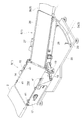
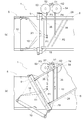
- FIG. 1 Perspective view of transfer device with branch conveyor switched to straight Perspective view of the transfer device with the branch conveyor switched to the branch state
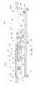
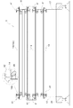
- Front view of the receiving conveyor The top view of the conveying apparatus which shows the state which conveys the articles
- the top view of the conveying apparatus which shows the state which conveys the article
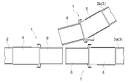
- the transport device is provided with a branch conveyor 1, an upstream conveyor 2, and a downstream conveyor 3 as transport units, and the upstream conveyor 2 is installed on the transport upstream side of the branch conveyor 1.
- a pair of downstream conveyors 3 including a straight downstream conveyor 3 a and a downstream downstream conveyor 3 b are installed on the downstream side of the branch conveyor 1.
- the conveying device switches the branch conveyor 1 to the straight traveling state (see FIG. 1) or the branching state (see FIG. 2), thereby transferring the articles transported from the upstream conveyor 2 to the downstream straight conveyor 3a or the downstream downstream conveyor 3b. It is configured to be selectively transportable.
- the conveyance direction (branch direction) of the branching downstream conveyor 3b is 30 ° counterclockwise in plan view with respect to the conveyance direction (straight direction) of the upstream conveyor 2 and the straight downstream conveyor 3a. Tilted.
- the horizontal direction orthogonal to the straight direction may be referred to as a lateral width direction.
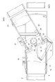
- the branch conveyor 1 includes a receiving conveyor 5 (corresponding to the conveying conveyor of the present invention) and a swing conveyor 6 (corresponding to the adjacent conveyor of the present invention) provided in a state adjacent to the conveying downstream side of the receiving conveyor 5. It is prepared for.
- the branch conveyor 1 has the upstream side of the receiving conveyor 5 as a first direction side that is one side in the conveying direction, and the downstream side of the receiving conveyor 5 that is the other side in the conveying direction. The direction side.
- the branching conveyor 1 has a straight traveling state in which articles are transported to the straight downstream conveyor 3 a and a branch in which articles are transported to the branching downstream conveyor 3 b as shown in FIGS. 2 and 5. It is configured to be switchable between states.
- the branch conveyor 1 is transported from the upstream conveyor 2 to the downstream conveyor 3a when it is switched to the straight state, and is transported from the upstream conveyor 2 when it is switched to the branch state.
- the articles are conveyed to the branching downstream conveyor 3b. 4 and 5 show a state in which a part is cut away.
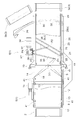
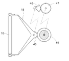
- the receiving conveyor 5 includes a plurality of rotating bodies 8 to 11 (a first conveying rotating body 8, a second conveying rotating body 9, a first relay rotating body) as a plurality of wound bodies.
- An acceptance conveyance motor 15 is provided as a conveyance drive device.
- the receiving conveyor 5 is configured such that the driving rotating body 12 is rotationally driven by the receiving and conveying motor 15 and the receiving endless belt 14 moves in the longitudinal direction thereof, whereby the receiving endless belt 14 faces upward.
- the article placed on is transported along the transport direction (straight direction).
- the first transfer rotator 8 is provided at the upstream end of the receiving conveyor 5 (one end in the transfer direction (first direction side) of the transfer portion 14a of the receiving endless belt 14).
- the two transport rotators 9 are provided at the transport downstream end of the receiving conveyor 5 (the end of the transport end portion 14a of the receiving endless belt 14 on the other side (second direction side) in the transport direction).
- the first relay rotator 10 is positioned below the first transfer rotator 8 and the second transfer rotator 9 and in the transfer direction, the first transfer rotator 8 and the second transfer rotator 9. Between the two.
- the second relay rotator 11 is provided below the first transfer rotator 8 and the second transfer rotator 9 and at the downstream side of the first relay rotator 10. .
- the second relay rotator 11 is located immediately below the second transfer rotator 9 (the same position in plan view).
- the driving rotator 12 is provided between the first transport rotator 8 and the first relay rotator 10 in the transport direction.
- the tension rotating body 13 is provided so as to be positioned upstream of the driving rotator 12 in the transport direction, and specifically, the first transport rotator 8 and the driving rotator 12 in the transport direction. Between.
- the first transfer rotator 8 and the second transfer rotator 9 are located at the same height, the first relay rotator 10 and the drive rotator 12 are located at the same height, and the second The relay rotating body 11 and the tension rotating body 13 are located at the same height.
- the receiving endless belt 14 includes a first transport rotator 8, a second transport rotator 9, a first relay rotator 10, a second relay rotator 11, a tension rotator 13, and a drive rotator 12.
- the first transfer rotator 8 is wound in this order, and the transfer surface is the surface facing the upper side of the transfer portion 14 a located between the first transfer rotator 8 and the second transfer rotator 9. Is formed.
- Each of the first transfer rotator 8, the second transfer rotator 9, the first relay rotator 10, the second relay rotator 11, the drive rotator 12, and the tension rotator 13 is rotatable. In the state, it is provided on the receiving conveyor 5, and the rotating bodies 8 to 13 rotate as the receiving endless belt 14 moves in the longitudinal direction.
- the first transfer rotator 8 corresponds to a first transfer roll
- the second transfer rotator 9 corresponds to a second transfer roll
- the first relay rotator 10 is a first transfer roll. It corresponds to the winding body for relay
- the second relay rotating body 11 corresponds to the second winding body for relay.
- the first conveying rotating body 8 In a state where the receiving conveyor 5 is installed in a state where the conveying surface is horizontal and the branch conveyor 1 is switched to the straight traveling state, the first conveying rotating body 8, the second conveying rotating body 9, and the first relay rotating
- the body 10 the second relay rotator 11, the drive rotator 12, and the tension rotator 13 has a rotation axis along the horizontal width direction, and the rotation axis direction of these rotators 8 to 13 is They are in a state of being parallel to each other.
- the receiving conveyor 5 includes a base frame 17 that supports the first transfer rotator 8, the drive rotator 12, and the tension rotator 13 around the rotation axis along the horizontal direction, and a first relay.
- the first support frame 18 that rotatably supports the rotating body 10 for rotation around the rotation axis along the horizontal direction, and the rotation axis 9 along the horizontal direction for the second transfer rotating body 9 and the second relay rotating body 11
- a second support frame 19 that is rotatably supported.
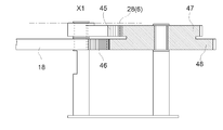
- the base frame 17 is connected and fixed to a base 20 that is fixed to the floor on which the receiving conveyor 5 (branch conveyor 1) is installed, and the first support frame 18 and the second support frame 19 are transported in the receiving conveyor 5. It is connected to the base 20 in a swingable manner around a first axis X1 (corresponding to a vertical axis) along the vertical direction located at the downstream end of the base.
- the receiving and conveying motor 15 is supported by the base frame 17.
- a support member 20a is erected on the base 20, and the first support frame 18 is connected to the support member 20a of the base 20 in a swingable manner around the first axis X1.
- the frame member 28 of the swing conveyor 6 is connected to the support member 20a so as to be swingable around the first axis X1
- the second support frame 19 is connected to the frame member 28.
- the support member 20a is connected to the support member 20a via the frame body 28 in a swingable manner around the first axis X1.
- the second transport rotator 9, the first relay rotator 10, and the second relay rotator 11 are around the first axis X1 located at the downstream end in the transport direction of the receiving conveyor 5. Is swingably supported.
- the first axial center X1 is located in the center in the lateral width direction of the receiving endless belt 14 in a plan view and is located downstream of the second conveying rotating body 9 in the conveying direction.
- the second transfer rotator 9 is shifted in the transfer direction by a radius shorter than the diameter of the second transfer rotator 9.
- the swing conveyor 6 includes an upstream rotating body 22, a downstream rotating body 23, a driving rotating body 24, a tension rotating body 25, a swing endless belt 26 wound around these rotating bodies 22 to 25, and a swing conveyance.
- a motor 27 is provided.
- the drive rotary body 24 is rotationally driven by the swing conveyance motor 27, so that the portion forming the conveyance surface of the endless belt 26 for swing moves in the conveyance direction.
- Each of the bodies 25 has a rotational axis along the lateral width direction, and the rotational axis directions of the rotary bodies 22 to 25 are parallel to each other.
- the swing conveyor 6 is provided with a frame body 28 that rotatably supports the upstream rotating body 22, the downstream rotating body 23, the driving rotating body 24, and the tension rotating body 25 around a rotation axis along the horizontal direction.
- the frame body 28 is connected to the base 20 so as to be swingable around the first axis X1 along the vertical direction.
- the first axis X1 is located on the upstream side of the frame 28 of the swing conveyor 6 (on the side where the receiving conveyor 5 is located in the transport direction).
- the swing conveyor 6 is connected to and supported by the base 20 and guides the end of the frame body 28 on the downstream side (the side opposite to the side where the receiving conveyor 5 is positioned in the transport direction) around the first axis X1.
- An arc-shaped guide rail 29 and a guide roller 30 connected to and supported by the frame body 28 and guided by the guide rail 29 are provided.
- the swing conveyor 6 is moved laterally from within the lateral width of the swing endless belt 26 of the branch conveyor 1 when the downstream end of the swing conveyor 6 is in the straight traveling state. It is configured to be out of the length.
- the branching conveyor 1 (receiving conveyor 5) is provided with an interlocking mechanism 33 (see FIG. 3) that interlocks the first support frame 18, the second support frame 19, and the frame body 28. It has been.
- the interlocking mechanism 33 swings the first support frame 18 around the first axis X1 as the second support frame 19 and the frame body 28 swing around the first axis X1.
- the first support frame 18, the second support frame 19, and the frame body 28 are interlocked so as to swing in the same direction as the direction and more than the swing amount by which the second support frame 19 swings (twice in this embodiment). I am letting.
- the second support frame 19 and the frame body 28 are integrally connected, and the second support frame 19 swings integrally with the swing conveyor 6 around the first axis X1. It is connected to the frame body 28. Therefore, as the frame body 28 swings around the first axis X1, the second support frame 19 has the same swing amount as the swing amount that the frame body 28 swings in the same direction as the swing direction of the frame body 28. It swings.
- the interlock mechanism 33 swings the swing conveyor 6 about the first axis X1 by the same swing amount as the swing amount of the second support frame 19 as the second support frame 19 swings around the first axis X1. Therefore, the swing conveyor 6 is configured to be interlocked with the first support frame 18 and the second support frame 19.
- the interlocking mechanism 33 includes a connecting member 38 that is driven to rotate about the second axis X2 along the vertical direction by a swinging motor 34 as a swinging drive device, and a base end portion connected to the connecting member 38 and a distal end.
- a first link body 35 having a portion connected to the first support frame 18, and a second link body 36 having a base end portion connected to the connection member 38 and a distal end portion connected to the frame body 28.
- the first interlocking member a for interlocking the first relay rotating body 10 with the swinging motor 34 is composed of a first link body 35 and a first support frame 18, and the swing conveyor 6 is connected to the swinging motor 34.
- the third interlocking member c to be interlocked with the second link body 36 is configured.
- the second interlocking member b for interlocking the second transport rotator 9 and the second relay rotator 11 with the swing motor 34 includes the second link body 36, the frame body 28 (swing conveyor 6), and the second support. It consists of a frame 19.
- connection location between the tip of the first link body 35 and the first support frame 18 is the first connection location P1
- connection location between the tip of the second link body 36 and the frame 28 is the second connection location P2.
- the linear distance in plan view from the second connection location P2 to the first axis X1 is approximately twice the linear distance in plan view from the first connection location P1 to the first axis X1. Is set. In such a distance relationship, the first link body 35 is connected to the first support frame 18, and the second link body 36 is connected to the frame body 28.
- the first connection point P1 and the second connection point P2 are moved by the same distance by a linear distance (string length), and the first support frame 18 is moved by 60 °, the second support frame. 19 and the frame body 28 are swung by 30 °, a linear distance (first swing radius r1) in a plan view from the first axis X1 to the first connection point P1, and a second distance from the first axis X1.
- the unit of angle (unit of “60” or “30” in the above formula) is degree.
- the first support frame 18 is moved while moving the first connection location P1 and the second connection location P2 by the same distance by a linear distance.
- the second support frame 19 and the frame body 28 can be doubled, and the winding path length at each position in the belt width direction when the posture of the branch conveyor 1 is switched can be reduced. Change can be suppressed.
- the base end portions of the first link body 35 and the second link body 36 are connected to a location eccentric from the second axis X2 in the connection member 38, and the base end portion of the first link body 35 and the connection member are connected.
- 38 as a third connection point P3
- the linear distance in plan view is equal to the linear distance in plan view from the fourth connecting point P4 to the second axis X2.
- the first link body 35 and the second link body 36 are connected to the connecting member 38.
- the first link body 35 is formed longer than the second link body 36.
- the first axial center X1 and the second connecting point P2 are located in the center of the receiving endless belt 14 and the swinging endless belt 26 in the lateral direction, and the first connecting point P1 is the receiving endless belt 14 and the swinging endless belt 26. Although it is located within the lateral width of the endless belt 26, the endless belts 14 and 26 are biased to one side (the side opposite to the side where the branching downstream conveyor 3b is located) from the central portion in the lateral width direction. positioned. Further, the swinging motor 34 and the connecting member 38 are located on the other side in the lateral width direction (the side where the branching downstream conveyor 3b is located) with respect to the receiving endless belt 14 and the swinging endless belt 26.
- the 1st connection location P1 is located in the conveyance downstream rather than the 1st axial center X1
- the 2nd connection location P2 is located in the conveyance downstream further than the 1st connection location P1.
- the swinging motor 34 and the connecting member 38 are provided so that at least a part is located between the first connecting point P1 and the second connecting point P2 in the transport direction.
- the first link body 35 and the second link body 36 are located between the base 20 and the frame body 28 in the vertical direction, and the frame body 28 (swing conveyor 6) It is arranged below.
- the first link body 35, the second link body 36, and the frame body 28 are disposed within the vertical width of the receiving conveyor 5 (within the vertical winding width of the receiving endless belt 14).
- the first connection point P1 when the branch conveyor 1 is switched to the straight traveling state, the first connection point P1 when the branch conveyor 1 is switched to the branch state, and the branch conveyor 1 are The third connection point P3 when switched to the straight travel state, the third connection point P3 when the branch conveyor 1 is switched to the branch state, and the second axis X2 are arranged in a straight line in a plan view. . Further, in the intermediate state between the straight traveling state and the branching state (the state in which the first support frame 18 is swung 30 ° counterclockwise from the straight traveling state), the first axial center X1 and the first connecting point P1 are connected.
- connection point P4 when the branching conveyor 1 is switched to the straight traveling state
- second connecting point P2 when the branching conveyor 1 is switched to the branching state and the fourth when the branching conveyor 1 is switched to the straight traveling state.
- the connection point P4, the fourth connection point P4 when the branch conveyor 1 is switched to the branched state, and the second axis X2 are arranged in a straight line in plan view.
- a line segment connecting the first axis X1 and the second connecting point P2 is used.
- a line segment connecting the second connection point P2 and the fourth connection point P4 are orthogonal to each other in plan view.
- the interlocking mechanism 33 includes the position of the first axis X1, the position of the second axis X2, the connection position of the first link body 35 with the connecting member 38 and the first support frame 18, and the second link body 36.
- the connecting member 38 Due to the relationship of the connecting position with the connecting member 38 and the frame body 28, the connecting member 38 is swung around the second axis X2 by driving the swinging motor 34, and the first link body 35 and the second link body 36 are moved.
- the first support frame 18 is configured to swing around the first axis X1 by twice the amount of swing of the second support frame 19 and the frame body 28.
- the interlocking mechanism 33 rotates the connecting member 38 from the state shown in FIG. 4 to the state shown in FIG.
- chord length is moved counterclockwise around X1 so that the chord length is the same distance, and the frame body 28 (swing conveyor 6) and the second support frame 19 connected thereto (the second transport rotary body 9 and the second The second relay rotator 11) is swung counterclockwise by 30 °, and the first support frame 18 (first relay rotator 10) is swung counterclockwise by 60 °.
- the receiving conveyor 5 is provided with a meandering prevention mechanism 41 for preventing the receiving endless belt 14 from meandering.
- the meandering prevention mechanism 41 is provided for each of both ends in the width direction of the receiving endless belt 14, and the pair of meandering prevention mechanisms 41 provided in this way is the longitudinal direction of the receiving endless belt 14. A plurality of sets are provided along the line.
- one side of the width direction of the pair of meander prevention mechanisms 41 (the side where the downstream downstream conveyor 3b is located) Only the meandering prevention mechanism 41 on the opposite side is provided so that the first support frame 18 and the meandering prevention mechanism 41 do not interfere when the receiving conveyor 5 is switched to the branched state.
- each of the meandering prevention mechanisms 41 is provided on the surface roller 42 that contacts the surface of the receiving endless belt 14 (the surface on the side on which the conveying surface is formed) and the back surface of the receiving endless belt 14.
- the roller 42 for back surface is comprised, and the roller 42 for surface and the roller 43 for back surface are provided in the state which pinches
- a chevron-shaped protrusion 14b is formed along the longitudinal direction of the receiving endless belt 14 at both ends of the receiving endless belt 14 in the width direction.
- the back roller 43 is provided in a posture in which the rotation axis is inclined corresponding to the inner inclined surface in the lateral width direction of the protrusion 14b.
- the surface roller 42 is provided in a posture in which the rotation axis is horizontal.
- the front roller 42 and the back roller 43 are provided at an interval narrower than the thickness of the portion of the receiving endless belt 14 where the projections 14b are formed, and the back roller 43 has a lateral width with respect to the projections 14b. The contact from the inner side in the direction prevents the receiving endless belt 14 from moving inward in the lateral width direction, thereby restricting the receiving endless belt 14 from meandering.
- the meandering prevention mechanism 41 that regulates the meandering of the transport portion 14a is supported by the base frame 17.
- the meandering prevention mechanism 41 that regulates the meandering of the transport portion 14a is supported by the base frame 17.
- the mechanism 41 does not swing around the first axis X1. Therefore, even if the branching conveyor 1 is switched from the straight traveling state to the branching state, the transporting portion 14a is maintained in a posture along the straight traveling direction, so that the transporting direction of the branching conveyor 1 is the same in the straight traveling state and the branching state. Yes.
- the branch conveyor 1 includes a first transfer rotor 9, a first relay rotor 10, and a second relay rotor 11 that are positioned along the vertical direction at the downstream end in the transport direction of the receiving conveyor 5. It is supported so as to be swingable around the axis X1.
- the second transport rotator 9 is located at the downstream end of the transport end portion 14a of the receiving endless belt 14 in the transport direction.
- the interlocking mechanism 33 causes the second transport rotator 9 and the second relay rotator 11 to swing integrally around the first axis X1, and the second transport rotator 9 and the second relay rotator.
- one branch conveyor 1 is provided between the upstream conveyor 2 and the downstream conveyor 3, but between the upstream conveyor 2 and the downstream conveyor 3, these upstream conveyor 2 and downstream conveyor.
- a plurality of branch conveyors 1 may be provided according to the number of three. That is, for example, as shown in FIGS. 7 and 8, in the case where one upstream conveyor 2 is provided and two downstream conveyors 3 are provided, the first branch conveyor 1 is disposed adjacent to the transport downstream side of the upstream conveyor 2.
- the second branch conveyor 1 may be provided in a state adjacent to the upstream conveyance side of the downstream straight conveyor 3a, and the third branch conveyor 1 may be provided in the state adjacent to the downstream conveyance downstream of the branch downstream conveyor 3b.
- the first to third branch conveyors 1 are configured in the same manner as the branch conveyor 1 of the above embodiment except that the length of the swing conveyor 6 in the transport direction is short.
- first branch conveyor 1 When three branch conveyors 1 are thus provided, for the first branch conveyor 1, one side in the transport direction (first direction side) is located on the upstream side of the transport, and the other side in the transport direction (second direction).
- the second branch conveyor 1 and the third branch conveyor 1 are located on the downstream side of the transport direction, and the transport direction The other side (second direction side) is provided on the upstream side of conveyance. Then, the first branch conveyor 1 and the second branch conveyor 1 are switched to the straight traveling state, the third branch conveyor 1 is switched to the branching state, and the articles conveyed from the upstream conveyor 2 are transferred to the straight downstream conveyor 3a.
- the first branch conveyor 1 and the second branch conveyor 1 are switched to the branched state, the third branch conveyor 1 is switched to the straight traveling state, and the articles conveyed from the upstream conveyor 2 are branched to the downstream downstream conveyor 3b. Can be conveyed.
- the transport equipment By configuring the transport equipment in this way, the length of the swing conveyor 6 in the transport direction can be shortened.
- the interlocking mechanism 33 is configured by including a plurality of link bodies 35 and 36, but the configuration of the interlocking mechanism 33 can be changed as appropriate. That is, the interlocking mechanism 33 may be configured as follows. As shown in FIGS. 9 to 11, the frame body 28 is provided with a sector gear 45 that rotates integrally around the frame body 28 and the first axis X 1, and the gear portion 46 is formed on the first support frame 18. A small-diameter gear 47 that meshes with the sector gear 45 and a large-diameter gear 48 that has a larger diameter than the small-diameter gear 47 and meshes with the gear portion 46 are provided so as to rotate integrally.
- Such a fan-shaped gear 45, a gear portion 46, a small-diameter gear 47, and a large-diameter gear 48 constitute the interlock mechanism 33, and an operator manually rotates the swing conveyor 6 around the first axis X1.
- the small-diameter gear 47 and the large-diameter gear 48 rotate so that the first support frame 18 swings in the same direction as the swing conveyor 6 swings, and the swing amount by which the swing conveyor 6 swings is swung. It is configured to swing by a swing amount twice as large as that.
- the second support frame 19 swings by the same amount as the swing amount of the swing conveyor 6 in the same direction as the swing conveyor 6 swings.
- the configuration of the interlocking mechanism 33 can be changed as appropriate. That is, as shown in FIG. 14, the reversing relay gear 52 is engaged with the output gear 51 that is driven to rotate about the second axis X2 by the unillustrated swinging motor 34, and the reversing relay gear 52 is engaged with the first reversing relay gear 52.
- the swinging rotation gear 53 is meshed, and the output gear 51 is meshed with the second swinging rotation gear 54.
- the base end portion of the first link body 35 is connected to the first swinging rotation gear 53
- the base end portion of the second link body 36 is connected to the second swinging rotation gear 54 to constitute the interlocking mechanism 33. May be.
- first support frame 18 (first relay rotator 10) is swung counterclockwise by 60 ° to bring the branch conveyor 1 into a branched state as shown in FIG. 14 (b). It is configured to switch.
- the swing motor 34 is provided as the swing drive device.
- another drive device such as a cylinder may be provided as the swing drive device.
- the swing drive device is provided and the first support frame 18 and the second support frame 19 are swung by the driving force of the swing drive device.
- the first support frame 18 and the second support frame 19 may be swung.
- the swing conveyor 6 is swung around the first axis X1 by a swinging drive device such as a cylinder, so that the interlocking mechanism 33 interlocks the connection.
- the first support frame 18 and the second support frame 19 may be swung, and the interlocking mechanism 33 can be operated by swinging the swing conveyor 6 around the first axis X1 manually by the operator.
- the first support frame 18 and the second support frame 19 that are linked and connected may be swung.
- the downstream conveyor 3a and the branching downstream conveyor 3b are provided as the downstream conveyor 3, and the branching conveyor 1 is switched between the straight traveling state and the branching state, whereby the articles are moved to the downstream downstream conveyor 3a.
- it is configured to selectively convey to the branching downstream conveyor 3b.
- the downstream conveyor 3 only one of the straight traveling downstream conveyor 3a and the branching downstream conveyor 3b is provided, and the downstream conveyor 3
- the branch conveyor 1 may be provided in a posture corresponding to the posture so that the state of the branch conveyor 1 is not switched during article conveyance.
- the branching conveyor 1 may be installed in a state of switching to the branching state, or only the downstream downstream conveyor 3a as the downstream conveyor 3 may be installed. It may be provided and installed with the branch conveyor 1 switched to the straight traveling state.
- the receiving conveyor 5 is provided on both sides of the upstream side and the downstream side of the swing conveyor 6.
- the branch conveyor 1 may be composed of two receiving conveyors 5 and one swing conveyor 6.
- the branching conveyor 1 may be composed of only one receiving conveyor 5, and in this case, it is necessary to install the downstream conveyor 3 on the upstream side of the conveyance as much as the swing conveyor 6 is not provided.
- the branching conveyor 1 is constituted by only one receiving conveyor 5 as described above, as shown in FIG. 13, the fan-shaped gear 45 is arranged around the first axis X1 in the first support frame 18.
- the second support frame 19 that is interlocked and connected by the interlocking mechanism 33 can be configured to swing by providing the first support frame 18 around the first axis X ⁇ b> 1.
- the second link body 36 may be directly connected to the second support frame 19, and the third interlocking member c may not be provided in the interlocking mechanism 33.
- one straight traveling downstream conveyor 3a and one branching downstream conveyor 3b are provided.
- one straight traveling downstream conveyor 3a and two branching downstream conveyors 3b are provided. It may be provided, and two downstream conveyors 3b may be provided without providing the straight downstream conveyor 3a.
- the second support frame 19 is swung by 30 ° when the branch conveyor 1 is switched from the straight travel state to the branch state.
- the swing angle of the support frame 19 can be changed as appropriate.
- the swing angle of the second support frame 19 when the branch conveyor 1 is switched from the straight traveling state to the branching state can be changed within a range of 15 ° to 40 °.
- a plurality of angles within a set angle range for example, 40 °.
- the second support frame 19 is swung by 15 ° from the straight traveling state to the first branch state, and the second support frame 19 is further moved from the first branch state. You may comprise so that it may rock
- the second conveyor frame 19 is swung to the one side (swung counterclockwise) from the state where the branch conveyor 1 is switched to the straight traveling state, but this branching is performed.
- the second support frame 19 may be switched to the branched state by swinging the second support frame 19 to the other side (clockwise) from the state where the branch conveyor 1 is switched to the straight traveling state. .
- meandering prevention mechanisms 41 are provided, but the number of meandering prevention mechanisms 41 may be changed as appropriate.
- the five meandering prevention mechanisms 41 provided for the conveyance portion 14a two (meandering prevention mechanisms 41 provided near the second conveyance rotating body 9) located on the conveyance downstream side Only the meandering prevention mechanism 41) provided near the receiving and conveying motor 15 may be provided.
- the receiving endless belt 14 is assumed to meander on only one side in the width direction, the end of the receiving endless belt 14 opposite to the direction in which the meandering in the width direction is assumed.
- the meandering prevention mechanism 41 may be provided only for the portion.
- the meandering of the receiving endless belt 14 only on one side by configuring the receiving conveyor 5 as follows. That is, in the state where the branch conveyor 1 is switched to the straight traveling state, the posture of a part of the wound body provided in the receiving conveyor 5 (for example, the first relay rotating body 10) is set to the other wound body. It is conceivable to set the direction of meandering by adopting a posture inclined about the vertical axis or the horizontal axis.
- the protrusion 14b is formed only on the back surface of the receiving endless belt 14, but the protrusion 14b may be formed only on the surface of the receiving endless belt 14, or the receiving endless belt.
- the protrusions 14 b may be formed on both the front surface and the back surface of 14.
- the surface roller 42 is provided in a posture in which the rotation axis is inclined corresponding to the inclined surface on the inner side of the protrusion 14b in the lateral width direction.
- one side (first direction side) in the transport direction is the transport upstream side
- the other side (second direction side) in the transport direction is the transport downstream side
- the first direction side) may be the downstream side of conveyance
- the other side (second direction side) of the conveyance direction may be the upstream side of conveyance.
- the first transfer winding body, the second transfer winding body, the first relay winding body, and the second relay winding body are rotatably provided, and these winding bodies are provided.
- the endless belt is rotated along with the movement of the endless belt, but part or all of these winding bodies are provided so as not to rotate, and the endless belt moves along the winding body along with the movement of the endless belt. You may make it slide.
- the driving rotator 12 and the transport driving device are supported by the base frame 17.
- the first relay rotator 10 is used as a driving rotator, and the first relay rotation is performed.
- the body 10 may be configured to be rotationally driven by the transport driving device, and the driving rotating body and the transport driving device may be supported by the first support frame 18.
Landscapes
- Engineering & Computer Science (AREA)
- Mechanical Engineering (AREA)
- Branching, Merging, And Special Transfer Between Conveyors (AREA)
- Framework For Endless Conveyors (AREA)
- Structure Of Belt Conveyors (AREA)
- Tyre Moulding (AREA)
Abstract
Description
ちなみに、特許文献1では、下流コンベヤとして本流コンベヤ12と分岐側コンベヤ13とが設けられており、これら本流コンベヤ12と分岐側コンベヤ13とは、搬送方向が互いに30°異なっている。そして、特許文献1に記載の搬送コンベヤ(ベルトジャンクションコンベヤ10)は、物品を本流コンベヤ12に受け渡すことができる第1搬送状態や、物品を分岐側コンベヤ13に受け渡すことができる第2搬送状態に切り換え自在に構成して、搬送方向が異なる本流コンベヤ12と分岐側コンベヤ13との両方に物品を適切に搬送できるようになっている。
そして、搬送コンベヤを、第一方向側に下流コンベヤが位置する状態で設け、第1搬送状態から、第1搬送用巻回体を縦軸心周りに時計回りに30°揺動させ、その第1搬送用巻回体の揺動により生じた無端ベルトにおける搬送部分の伸縮を、第1中継用巻回体を縦軸心周りに反時計回りに30°揺動させることで吸収して、第2搬送状態に切り換えるように構成されている。
前記複数の巻回体として、前記無端ベルトにおける前記搬送面を形成する搬送部分の搬送方向の一方側である第一方向側の端部に位置する第1搬送用巻回体と、前記搬送部分の搬送方向の他方側である第二方向側の端部に位置する第2搬送用巻回体と、前記第1搬送用巻回体及び前記第2搬送用巻回体より下方に位置し且つ搬送方向において前記第1搬送用巻回体と前記第2搬送用巻回体との間に位置する第1中継用巻回体と、前記第1搬送用巻回体及び前記第2搬送用巻回体より下方に位置し且つ搬送方向において前記第1中継用巻回体より前記第二方向側に位置する第2中継用巻回体と、が設けられ、前記無端ベルトは、前記第1搬送用巻回体、前記第2搬送用巻回体、前記第1中継用巻回体、前記第2中継用巻回体、前記第1搬送用巻回体の順に巻回され、前記第2搬送用巻回体、前記第1中継用巻回体及び前記第2中継用巻回体が、前記第二方向側の端部に位置する上下方向に沿う縦軸心周りに揺動自在に支持され、前記第2搬送用巻回体と前記第2中継用巻回体とを前記縦軸心周りに一体的に揺動させ且つ前記第2搬送用巻回体及び前記第2中継用巻回体が揺動する方向にこれら前記第2搬送用巻回体及び前記第2中継用巻回体の揺動量より多く前記第1中継用巻回体を前記縦軸心周りに揺動させるべく、前記第2搬送用巻回体と前記第1中継用巻回体と前記第2中継用巻回体とを連動揺動させる連動機構が設けられている。
また、第1中継用巻回体を、第2搬送用巻回体及び第2中継用巻回体が揺動する方向にこれら第2搬送用巻回体及び第2中継用巻回体の揺動量に対して所望の揺動量だけ多く縦軸心周りに揺動させることで、第2搬送用巻回体及び第2中継用巻回体を縦軸心周りに揺動させることで生じた無端ベルトにおける搬送部分の伸縮を吸収して、ベルト幅方向での各位置での巻回経路長の変化を抑制できる。特に、第1中継用巻回体の揺動量を、第2搬送用巻回体及び第2中継用巻回体の揺動量の2倍に設定することで、ベルト幅方向での各位置での巻回経路長の変化を適切に抑制できる。
従って、下流側に設けられた下流コンベヤの搬送方向が自身の搬送方向とは異なる場合でも対応できながら横幅方向にコンパクトに構成できる搬送コンベヤを提供することができるに至った。
前記搬送コンベヤに対して前記第二方向側に隣接する隣接コンベヤが設けられ、前記連動機構が、前記隣接コンベヤと前記第2搬送用巻回体及び前記第2中継用巻回体とを前記縦軸心周りに一体的に揺動させるべく、前記隣接コンベヤと前記第2搬送用巻回体と前記第2中継用巻回体とを連動揺動させるように構成されている点にある。
そして、隣接コンベヤが縦軸心周りに揺動することで、例えば、隣接コンベヤの第二方向側(搬送方向における搬送コンベヤとは反対側)に一対の下流コンベヤを横幅方向に並ぶ状態で複数設けた場合に、それら一対の下流コンベヤの夫々に対して物品を受け渡すことができる。
また、隣接コンベヤは、搬送コンベヤのような複数の巻回体のうちの一部の巻回体を揺動させるような特殊なコンベヤに構成する必要がないため、搬送コンベヤにおける第1中継用巻回体や第2中継用巻回体に相当するものを備える必要がなく、これにより隣接コンベヤの上下方向での幅を搬送コンベヤよりコンパクトで且つ軽量に構成し易い。また、隣接コンベヤの上下方向での幅を搬送コンベヤよりコンパクトに構成することで、隣接コンベヤの下方に連動機構を配置することができ、搬送ユニット全体での平面視での大きさをコンパクトに構成することができる。さらに、第2搬送用巻回体、第1中継用巻回体、第2中継用巻回体及び隣接コンベヤの前記縦軸心周りでの回転方向が、すべて同じ方向となるため、これらを揺動操作する構成の簡素化を図り易くなる。
また、上下方向での幅がコンパクトに構成されている隣接コンベヤの下方空間を利用して第1連動部材及び第3連動部材を設けることで、これら第1連動部材及び第3連動部材を搬送コンベヤや隣接コンベヤの横側方に設ける場合に比べて、搬送ユニットを平面視でコンパクトに構成することができる。
そして、第1連動部材と第3連動部材とを移動させて、第1連結箇所及び第2連結箇所を縦軸心周りに同じ方向で且つ直線距離で同じ距離移動させることで、第2支持枠及び隣接コンベヤが揺動する方向にこれら第2支持枠及び隣接コンベヤに対して所望の揺動量だけ多く第1支持枠を縦軸心周りに揺動させることができる。
このように、第2支持枠及び隣接コンベヤが揺動する方向にこれら第2支持枠及び隣接コンベヤの揺動量より多く(例えば当該揺動量の2倍だけ)第1支持枠を縦軸心周りに揺動させるときに、第1連動部材により移動させる第1連結箇所の揺動方向及び移動距離と、第3連動部材により移動させる第2連結箇所の揺動方向と移動距離とが同じであるため、これら第1連動部材及び第3連動部材を備えた連動機構を設計し易くなる。
ちなみに、上述の如く、第1連結箇所及び第2連結箇所を直線距離(弦長)で同じ距離移動させて、第1支持枠をθ1、第2支持枠及び隣接コンベヤをθ2で揺動させる場合、縦軸心から第1連結箇所までの距離である第1揺動半径r1と、縦軸心から第2連結箇所までの距離である第2揺動半径r2との関係は、
2・r1・sin(θ1/2)=2・r2・sin(θ2/2)
となる。なお、角度の単位はラジアンである。
図1及び図2に示すように、搬送装置には、搬送ユニットとしての分岐コンベヤ1、上流コンベヤ2及び下流コンベヤ3が設けられており、分岐コンベヤ1の搬送上流側に上流コンベヤ2が設置され、分岐コンベヤ1の搬送下流側に直進用下流コンベヤ3aと分岐用下流コンベヤ3bとの一対の下流コンベヤ3が設置されている。
尚、本実施形態では、分岐用下流コンベヤ3bの搬送方向(分岐方向)は、上流コンベヤ2及び直進用下流コンベヤ3aの搬送方向(直進方向)に対して、平面視で反時計回りに30°傾いている。また、直進方向に対して直交する水平方向を横幅方向と称して説明する場合がある。
図3~図5に示すように、受入コンベヤ5には、複数の巻回体としての回転体8~11(第1搬送用回転体8、第2搬送用回転体9、第1中継用回転体10、第2中継用回転体11)と駆動用回転体12とテンション用回転体13とに亘って巻回された無端ベルトとしての受入用無端ベルト14と、駆動用回転体12を回転駆動させる搬送用駆動装置としての受入搬送用モータ15と、が設けられている。そして、受入コンベヤ5は、駆動用回転体12が受入搬送用モータ15にて回転駆動されて受入用無端ベルト14がその長手方向に移動することで、受入用無端ベルト14における上方を向く搬送面に載置された物品を搬送方向(直進方向)に沿って搬送するように構成されている。
また、第1中継用回転体10は、第1搬送用回転体8及び第2搬送用回転体9より下方に位置し且つ搬送方向において第1搬送用回転体8と第2搬送用回転体9との間に位置するように設けられている。第2中継用回転体11は、第1搬送用回転体8及び第2搬送用回転体9より下方に位置し且つ第1中継用回転体10より搬送下流側に位置するように設けられている。本実施形態では、第2中継用回転体11は、第2搬送用回転体9の直下(平面視で同じ位置)に位置している。駆動用回転体12は、搬送方向において第1搬送用回転体8と第1中継用回転体10との間に設けられている。テンション用回転体13は、搬送方向において駆動用回転体12より搬送上流側に位置するように設けられており、具体的には、搬送方向において第1搬送用回転体8と駆動用回転体12との間に設けられている。
また、第1搬送用回転体8と第2搬送用回転体9とは同じ高さに位置し、第1中継用回転体10と駆動用回転体12とは同じ高さに位置し、第2中継用回転体11とテンション用回転体13とは同じ高さに位置している。
このようにして、第2搬送用回転体9、第1中継用回転体10及び第2中継用回転体11が、受入コンベヤ5における搬送方向の下流側端部に位置する第1軸心X1周りに揺動自在に支持されている。
ちなみに、第1軸心X1は、平面視において受入用無端ベルト14の横幅方向の中央に位置し且つ第2搬送用回転体9より搬送方向下流側に位置しており、第1軸心X1と第2搬送用回転体9とは、第2搬送用回転体9の直径より短い半径程度だけ搬送方向にずれている。
スイングコンベヤ6には、上流側回転体22、下流側回転体23、駆動回転体24、テンション回転体25、これらの回転体22~25に巻回されたスイング用無端ベルト26、及び、スイング搬送用モータ27が設けられている。そして、スイング搬送用モータ27にて駆動回転体24が回転駆動されることで、スイング用無端ベルト26の搬送面を形成する部分が搬送方向に移動するように構成されている。また、搬送面が水平となる状態でスイングコンベヤ6が設置され且つ分岐コンベヤ1が直進状態に切り換えられている状態では、上流側回転体22、下流側回転体23、駆動回転体24、テンション回転体25の夫々は、回転軸心が横幅方向に沿っており、これらの回転体22~25の回転軸心方向が互いに平行となる状態となっている。
ちなみに、スイングコンベヤ6は、分岐コンベヤ1が分岐状態に切り換えられたときに、スイングコンベヤ6の搬送下流側の端部が直進状態での分岐コンベヤ1のスイング用無端ベルト26の横幅内から横側方に外れる長さに構成されている。
図4及び図5に示すように、分岐コンベヤ1(受入コンベヤ5)には、第1支持枠18と第2支持枠19と枠体28とを連動させる連動機構33(図3参照)が設けられている。
この連動機構33は、第2支持枠19及び枠体28が第1軸心X1周りに揺動するに伴って第1支持枠18を第1軸心X1周りに第2支持枠19の揺動方向と同じ方向で且つ第2支持枠19が揺動する揺動量より多く(本実施形態では2倍)揺動させるべく、第1支持枠18と第2支持枠19と枠体28とを連動させている。
連動機構33には、揺動用駆動装置としての揺動用モータ34にて上下方向に沿う第2軸心X2周りに回転駆動される連結部材38と、基端部が連結部材38に連結され且つ先端部が第1支持枠18に連結された第1リンク体35と、基端部が連結部材38に連結され且つ先端部が枠体28に連結された第2リンク体36と、を備えて構成されている。尚、第1中継用回転体10を揺動用モータ34に連動させる第1連動部材aは、第1リンク体35と第1支持枠18とで構成されており、スイングコンベヤ6を揺動用モータ34に連動させる第3連動部材cは、第2リンク体36にて構成されている。また、第2搬送用回転体9及び第2中継用回転体11を揺動用モータ34に連動させる第2連動部材bは、第2リンク体36と枠体28(スイングコンベヤ6)と第2支持枠19とで構成されている。
ちなみに、図4及び図5で示すように、第1連結箇所P1及び第2連結箇所P2を直線距離(弦長)で同じ距離移動させて、第1支持枠18を60°、第2支持枠19及び枠体28を30°揺動させる場合では、第1軸心X1から第1連結箇所P1の平面視での直線距離(第1揺動半径r1)と、第1軸心X1から第2連結箇所P2の平面視での直線距離(第2揺動半径r2)との関係は、
2・r1・sin(60/2)=2・r2・sin(30/2)
となる。なお、角度の単位(上記の式中の“60”や“30”の単位)は度である。
第1揺動半径r1と第2揺動半径r2とをこのような関係とすることで、第1連結箇所P1及び第2連結箇所P2を直線距離で同じ距離移動させながら、第1支持枠18の揺動量を第2支持枠19及び枠体28の揺動量の2倍とすることができ、分岐コンベヤ1の姿勢を切り換えたときの、ベルト幅方向での各位置での巻回経路長の変化を抑制することができる。
また、図4及び図5に示すように、第1リンク体35は、第2リンク体36より長く形成されている。
また、揺動用モータ34及び連結部材38は、受入用無端ベルト14やスイング用無端ベルト26に対して横幅方向の他方側(分岐用下流コンベヤ3bが位置する側)に位置している。
また、第1連結箇所P1は、第1軸心X1よりも搬送下流側に位置しており、第2連結箇所P2は、第1連結箇所P1よりもさらに搬送下流側に位置している。そして、搬送方向において第1連結箇所P1と第2連結箇所P2との間に少なくとも一部が位置するように、揺動用モータ34及び連結部材38が設けられている。
また、図3に示すように、第1リンク体35及び第2リンク体36は、上下方向において基台20と枠体28との間に位置しており、枠体28(スイングコンベヤ6)の下方に配設されている。そして、第1リンク体35、第2リンク体36及び枠体28は、受入コンベヤ5の上下幅内(受入用無端ベルト14の上下方向での巻回幅内)に配設されている。
同様に、分岐コンベヤ1を直進状態に切り換えたときの第2連結箇所P2、分岐コンベヤ1を分岐状態に切り換えたときの第2連結箇所P2、分岐コンベヤ1を直進状態に切り換えたときの第4連結箇所P4、分岐コンベヤ1を分岐状態に切り換えたときの第4連結箇所P4、及び第2軸心X2が、平面視で一直線上に並ぶようになっている。また、直進状態と分岐状態との中間の状態(直進状態から枠体28を反時計回りに15°揺動させた状態)において、第1軸心X1と第2連結箇所P2とを結ぶ線分と第2連結箇所P2と第4連結箇所P4とを結ぶ線分とが平面視で直交するようになっている。
そして、連動機構33は、第1軸心X1の位置、第2軸心X2の位置、第1リンク体35の連結部材38や第1支持枠18との連結位置、及び第2リンク体36の連結部材38や枠体28との連結位置等の関係から、揺動用モータ34の駆動により連結部材38を第2軸心X2周りに揺動させて第1リンク体35及び第2リンク体36を動かすことで、第1連結箇所P1及び第2連結箇所P2を第1軸心X1周りに同じ方向で且つ直線距離で同じ距離移動させて、第2支持枠19及び枠体28が揺動する方向に第2支持枠19及び枠体28の揺動量の2倍だけ第1支持枠18を第1軸心X1周りに揺動させるように構成されている。
具体的には、連動機構33は、図4に示す状態から図5に示す状態に、連結部材38が180°回転することで、第1連結箇所P1及び第2連結箇所P2を第1軸心X1周りに反時計回りに弦長が同じ距離となるように移動させて、枠体28(スイングコンベヤ6)及びこれに連結されている第2支持枠19(第2搬送用回転体9及び第2中継用回転体11)を反時計回りに30°揺動させるとともに、第1支持枠18(第1中継用回転体10)を反時計回りに60°揺動させるように構成されている。
この蛇行防止機構41は、受入用無端ベルト14の横幅方向の両端部の夫々に対して設けられており、このように設けられた一対の蛇行防止機構41は、受入用無端ベルト14の長手方向に沿って複数組設けられている。尚、搬送部分14aの搬送下流側端部に対して設けられている蛇行防止機構41については、一対の蛇行防止機構41のうちの横幅方向の一方側(分岐用下流コンベヤ3bが位置する側とは反対側)の蛇行防止機構41のみが設けられており、受入コンベヤ5を分岐状態に切り換えたときに第1支持枠18と蛇行防止機構41とが干渉しないようになっている。
連動機構33により、第2搬送用回転体9と第2中継用回転体11とを第1軸心X1周りに一体的に揺動させ且つ第2搬送用回転体9及び第2中継用回転体11が揺動する方向に第2搬送用回転体9及び第2中継用回転体11の揺動量の2倍だけ第1中継用回転体10を第1軸心X1周りに揺動させるべく、第2搬送用回転体9と第1中継用回転体10と第2中継用回転体11とが連動揺動されている。
そして、第1軸心X1が、第2搬送用回転体9が設けられている搬送方向の下流側端部に位置しているため、第2搬送用回転体9の揺動半径が小さくなり、第2搬送用回転体9を小さなスペースで揺動させることができる。
(1)上記実施形態では、上流コンベヤ2と下流コンベヤ3との間に、分岐コンベヤ1を1台設けたが、上流コンベヤ2と下流コンベヤ3との間に、これらの上流コンベヤ2及び下流コンベヤ3の台数に応じて分岐コンベヤ1を複数台設けてもよい。
つまり、例えば、図7及び8に示すように、上流コンベヤ2を1台設け、下流コンベヤ3を2台設ける場合では、上流コンベヤ2の搬送下流側に隣接する状態で第1の分岐コンベヤ1を設け、直進用下流コンベヤ3aの搬送上流側に隣接する状態で第2の分岐コンベヤ1を設け、分岐用下流コンベヤ3bの搬送下流側に隣接する状態で第3の分岐コンベヤ1を設けてもよい。
ちなみに、第1~第3の分岐コンベヤ1は、スイングコンベヤ6の搬送方向での長さが短い以外は、上記実施形態の分岐コンベヤ1と同様に構成されている。
このように搬送設備を構成することで、スイングコンベヤ6の搬送方向での長さを短くすることができる。
つまり、連動機構33を次のように構成してもよい。
図9~図11に示すように、枠体28に、この枠体28と第1軸心X1周りに一体回転する扇形ギヤ45を設け、第1支持枠18に、ギヤ部分46を形成する。そして、扇形ギヤ45に噛合する小径ギヤ47と、この小径ギヤ47より大径で且つギヤ部分46に噛合する大径ギヤ48とを、一体回転する状態で設ける。
このような扇形ギヤ45、ギヤ部分46、小径ギヤ47、及び大径ギヤ48を備えて連動機構33を構成し、作業者が手作業でスイングコンベヤ6を第1軸心X1周りに回転操作することで、小径ギヤ47及び大径ギヤ48が回転して、第1支持枠18が、スイングコンベヤ6を揺動させた方向と同じ方向に揺動するとともに、スイングコンベヤ6が揺動した揺動量の倍の揺動量だけ揺動するように構成されている。また、第2支持枠19は、スイングコンベヤ6を揺動させた方向と同じ方向にスイングコンベヤ6の揺動量と同じ量だけ揺動する。
つまり、図14に示すように、図外の揺動用モータ34にて第2軸心X2周りに回転駆動される出力ギヤ51に反転用中継ギヤ52を咬合させ、反転用中継ギヤ52に第1揺動用回転ギヤ53を噛合させ、出力ギヤ51に第2揺動用回転ギヤ54を噛合させる。そして、第1リンク体35の基端部を第1揺動用回転ギヤ53に連結し、第2リンク体36の基端部を第2揺動用回転ギヤ54に連結させて、連動機構33を構成してもよい。
図14(a)に示すように分岐コンベヤ1を直進状態に切り換えた状態から、揺動用モータ34にて出力ギヤ51及び反転用中継ギヤ52を所定量だけ回転駆動させることで、第1揺動用回転ギヤ53が反時計回りに回転し、第2揺動用回転ギヤ54が時計回りに回転する。これにより、連動機構33は、第1リンク体35及び第2リンク体36が移動して、第1連結箇所P1及び第2連結箇所P2が第1軸心X1周りに反時計回りに弦長が同じ距離となるように移動し、枠体28(スイングコンベヤ6)及びこれに連結されている第2支持枠19(第2搬送用回転体9及び第2中継用回転体11)を反時計回りに30°揺動させるとともに、第1支持枠18(第1中継用回転体10)を反時計回りに60°揺動させて、図14(b)に示すように分岐コンベヤ1を分岐状態に切り換えるように構成されている。
また、上記実施形態では、揺動用駆動装置を設けて、揺動用駆動装置の駆動力により、第1支持枠18及び第2支持枠19を揺動させたが、作業者の手作業により、これら第1支持枠18及び第2支持枠19を揺動させてもよい。
具体例を挙げると、上記した別実施形態(2)において、シリンダ等の揺動用駆動装置にてスイングコンベヤ6を第1軸心X1周りに揺動させることで、連動機構33にて連動連結された第1支持枠18及び第2支持枠19を揺動させてもよく、また、作業者の手作業でスイングコンベヤ6を第1軸心X1周りに揺動させることで、連動機構33にて連動連結された第1支持枠18及び第2支持枠19を揺動させてもよい。
具体的には、例えば、下流コンベヤ3として分岐用下流コンベヤ3bのみを設けて、分岐コンベヤ1を分岐状態に切り換えた状態で設置してもよく、また、下流コンベヤ3として直進用下流コンベヤ3aのみ設けて、分岐コンベヤ1を直進状態に切り換えた状態で設置してもよい。
また、上記実施形態では、分岐コンベヤ1を直進状態に切り換えられている状態から第2支持枠19を一方側に揺動(反時計回りに揺動)させて分岐状態に切り換えたが、この分岐状態に加えて又は代えて、分岐コンベヤ1を直進状態に切り換えられている状態から第2支持枠19を他方側に揺動(時計回りに揺動)させて分岐状態に切り換えるようにしてもよい。
また、受入用無端ベルト14が横幅方向の一方側のみに受入用無端ベルト14の蛇行が想定される場合は、受入用無端ベルト14の横幅方向における蛇行が想定される方向とは反対側の端部に対してのみ蛇行防止機構41を設けてもよい。ちなみに、例えば、受入コンベヤ5を次のように構成することで受入用無端ベルト14の蛇行を一方側のみに設定することが考えられる。すなわち、分岐コンベヤ1を直進状態に切り換えた状態において、受入コンベヤ5に設けられている巻回体の一部(例えば、第1中継用回転体10)の姿勢を、他の巻回体に対して上下軸心又は左右軸心周りに傾けた姿勢とすることで、蛇行の方向を設定することが考えられる。
5 搬送コンベヤ
6 隣接コンベヤ
8 第1搬送用巻回体
9 第2搬送用巻回体
10 第1中継用巻回体
11 第2中継用巻回体
12 駆動用回転体
14 無端ベルト
15 搬送用駆動装置
17 基枠
18 第1支持枠
19 第2支持枠
33 連動機構
a 第1連動部材
b 第2連動部材
c 第3連動部材
X 縦軸心
Claims (8)
- 複数の巻回体と駆動用回転体とに亘って巻回された無端ベルトと、前記駆動用回転体を回転駆動させる搬送用駆動装置とが設けられ、前記駆動用回転体が前記搬送用駆動装置にて回転駆動されて前記無端ベルトがその長手方向に移動することで、前記無端ベルトにおける上方を向く搬送面に載置された物品を搬送方向に沿って搬送する搬送コンベヤであって、
前記複数の巻回体として、
前記無端ベルトにおける前記搬送面を形成する搬送部分の搬送方向の一方側である第一方向側の端部に位置する第1搬送用巻回体と、
前記搬送部分の搬送方向の他方側である第二方向側の端部に位置する第2搬送用巻回体と、
前記第1搬送用巻回体及び前記第2搬送用巻回体より下方に位置し且つ搬送方向において前記第1搬送用巻回体と前記第2搬送用巻回体との間に位置する第1中継用巻回体と、
前記第1搬送用巻回体及び前記第2搬送用巻回体より下方に位置し且つ搬送方向において前記第1中継用巻回体より前記第二方向側に位置する第2中継用巻回体と、が設けられ、
前記無端ベルトは、前記第1搬送用巻回体、前記第2搬送用巻回体、前記第1中継用巻回体、前記第2中継用巻回体、前記第1搬送用巻回体の順に巻回され、
前記第2搬送用巻回体、前記第1中継用巻回体及び前記第2中継用巻回体が、搬送コンベヤの前記第二方向側の端部に位置する上下方向に沿う縦軸心周りに揺動自在に支持され、
前記第2搬送用巻回体と前記第2中継用巻回体とを前記縦軸心周りに一体的に揺動させ且つ前記第2搬送用巻回体及び前記第2中継用巻回体が揺動する方向に前記第2搬送用巻回体及び前記第2中継用巻回体の揺動量より多く前記第1中継用巻回体を前記縦軸心周りに揺動させるべく、前記第2搬送用巻回体と前記第1中継用巻回体と前記第2中継用巻回体とを連動揺動させる連動機構が設けられている搬送コンベヤ。 - 前記第1搬送用巻回体、前記第2搬送用巻回体、前記第1中継用巻回体及び前記第2中継用巻回体の夫々が、前記無端ベルトがその長手方向に移動するに伴って水平方向に沿う回転軸心周りに回転自在に設けられている請求項1記載の搬送コンベヤ。
- 前記第1中継用巻回体を支持し且つ前記縦軸心周りに揺動自在な第1支持枠と、
前記第2搬送用巻回体及び前記第2中継用巻回体を支持し且つ前記縦軸心周りに揺動自在な第2支持枠と、
前記第1搬送用巻回体を支持し且つ前記縦軸心周りに対して位置固定状態で設けられた基枠と、が設けられ、
前記駆動用回転体及び前記搬送用駆動装置が、前記基枠に支持されている請求項1又は2記載の搬送コンベヤ。 - 前記連動機構が、前記第1中継用巻回体を揺動用駆動装置に連動させる第1連動部材と、前記第2搬送用巻回体及び前記第2中継用巻回体を前記揺動用駆動装置に連動させる第2連動部材とを備え、前記揺動用駆動装置の駆動により前記第1連動部材及び前記第2連動部材を移動させて、前記第1中継用巻回体と前記第2搬送用巻回体と前記第2中継用巻回体とを連動揺動させるように構成されている請求項1~3のいずれか1項に記載の搬送コンベヤ。
- 請求項1~4のいずれか1項に記載の搬送コンベヤが備えられている搬送ユニットであって、
前記搬送コンベヤに対して前記第二方向側に隣接する隣接コンベヤが設けられ、
前記連動機構が、前記隣接コンベヤと前記第2搬送用巻回体及び前記第2中継用巻回体とを前記縦軸心周りに一体的に揺動させるべく、前記隣接コンベヤと前記第2搬送用巻回体と前記第2中継用巻回体とを連動揺動させるように構成されている搬送ユニット。 - 前記隣接コンベヤが、前記縦軸心周りに揺動自在に設けられ、
前記連動機構が、前記第1中継用巻回体を揺動用駆動装置に連動させる第1連動部材と、前記第2搬送用巻回体及び前記第2中継用巻回体を前記揺動用駆動装置に連動させる第2連動部材と、前記隣接コンベヤを前記揺動用駆動装置に連動させる第3連動部材と、を備え、前記揺動用駆動装置の駆動により前記第1連動部材、前記第2連動部材及び前記第3連動部材を移動させて、前記第1中継用巻回体と前記第2搬送用巻回体と前記第2中継用巻回体と前記隣接コンベヤとを連動揺動させるように構成されている請求項5記載の搬送ユニット。 - 前記第2搬送用巻回体及び前記第2中継用巻回体が、前記隣接コンベヤと前記縦軸心周りに一体的に揺動する状態で前記隣接コンベヤに取り付けられ、
前記第3連動部材と前記隣接コンベヤとで、前記第2連動部材が構成され、
前記第1連動部材及び前記第3連動部材が、前記隣接コンベヤの下方に設けられている請求項6記載の搬送ユニット。 - 前記第1中継用巻回体を支持する第1支持枠が、前記縦軸心周りに揺動自在に設けられ、
前記第2搬送用巻回体及び前記第2中継用巻回体を支持する第2支持枠が、前記縦軸心周りに前記隣接コンベヤと一体的に揺動する状態で前記隣接コンベヤに連結され、
前記第3連動部材と前記隣接コンベヤとで、前記第2連動部材が構成され、
前記第1連動部材を前記第1支持枠に連結した箇所を第1連結箇所とし、
前記第3連動部材を前記隣接コンベヤに連結した箇所を第2連結箇所として、
前記連動機構が、
前記揺動用駆動装置の設定量の駆動により、前記第1連動部材及び前記第3連動部材が移動することで、前記第1連結箇所及び前記第2連結箇所が前記縦軸心周りに同じ方向で且つ直線距離で同じ距離移動するように構成され、
前記縦軸心から前記第1連結箇所までの距離である第1揺動半径及び前記縦軸心から前記第2連結箇所までの距離である第2揺動半径の関係が、前記第1支持枠の揺動量及び第2支持枠の揺動量の関係に基づいて設定されている請求項6又は7記載の搬送ユニット。
Priority Applications (11)
| Application Number | Priority Date | Filing Date | Title |
|---|---|---|---|
| PCT/JP2014/059191 WO2015145739A1 (ja) | 2014-03-28 | 2014-03-28 | 搬送コンベヤ及び搬送ユニット(transport conveyor and transport unit) |
| AU2014388617A AU2014388617B2 (en) | 2014-03-28 | 2014-03-28 | Transport conveyor and transport unit |
| ES14886779T ES2716125T3 (es) | 2014-03-28 | 2014-03-28 | Cinta transportadora y unidad de transporte |
| CN201480077671.6A CN106458456B (zh) | 2014-03-28 | 2014-03-28 | 输送传送器及输送单元 |
| RU2016142219A RU2637854C1 (ru) | 2014-03-28 | 2014-03-28 | Транспортный конвейер и транспортное устройство |
| DK14886779.9T DK3124406T3 (en) | 2014-03-28 | 2014-03-28 | Conveyor belt and conveyor unit |
| SG11201607994YA SG11201607994YA (en) | 2014-03-28 | 2014-03-28 | Transport conveyor and transport unit |
| NZ724962A NZ724962A (en) | 2014-03-28 | 2014-03-28 | Transport conveyor and transport unit |
| EP14886779.9A EP3124406B1 (en) | 2014-03-28 | 2014-03-28 | Transport conveyor and transport unit |
| CA2944353A CA2944353C (en) | 2014-03-28 | 2014-03-28 | Transport conveyor and transport unit |
| US15/129,994 US9725245B2 (en) | 2014-03-28 | 2014-03-28 | Transport conveyor and transport unit |
Applications Claiming Priority (1)
| Application Number | Priority Date | Filing Date | Title |
|---|---|---|---|
| PCT/JP2014/059191 WO2015145739A1 (ja) | 2014-03-28 | 2014-03-28 | 搬送コンベヤ及び搬送ユニット(transport conveyor and transport unit) |
Publications (1)
| Publication Number | Publication Date |
|---|---|
| WO2015145739A1 true WO2015145739A1 (ja) | 2015-10-01 |
Family
ID=54194327
Family Applications (1)
| Application Number | Title | Priority Date | Filing Date |
|---|---|---|---|
| PCT/JP2014/059191 WO2015145739A1 (ja) | 2014-03-28 | 2014-03-28 | 搬送コンベヤ及び搬送ユニット(transport conveyor and transport unit) |
Country Status (11)
| Country | Link |
|---|---|
| US (1) | US9725245B2 (ja) |
| EP (1) | EP3124406B1 (ja) |
| CN (1) | CN106458456B (ja) |
| AU (1) | AU2014388617B2 (ja) |
| CA (1) | CA2944353C (ja) |
| DK (1) | DK3124406T3 (ja) |
| ES (1) | ES2716125T3 (ja) |
| NZ (1) | NZ724962A (ja) |
| RU (1) | RU2637854C1 (ja) |
| SG (1) | SG11201607994YA (ja) |
| WO (1) | WO2015145739A1 (ja) |
Families Citing this family (10)
| Publication number | Priority date | Publication date | Assignee | Title |
|---|---|---|---|---|
| CN109928166B (zh) * | 2017-12-15 | 2021-03-02 | 中车齐齐哈尔车辆有限公司 | 传送带转向装置及装卸机 |
| CN110626769A (zh) * | 2018-06-25 | 2019-12-31 | 安徽省宁国市宁星耐磨材料有限公司 | 铸钢件包装箱传送装置及其方法 |
| KR102604693B1 (ko) * | 2018-10-04 | 2023-11-20 | 엘지전자 주식회사 | 의류 처리 장치 |
| EP3750403B1 (en) * | 2019-06-12 | 2023-08-02 | Radie B.V. | Device for aligning dough pieces |
| CN110654824A (zh) * | 2019-10-28 | 2020-01-07 | 广州市贝云科技有限公司 | 流水线输运装置 |
| CN111301928B (zh) * | 2020-02-27 | 2021-03-09 | 中车齐齐哈尔车辆有限公司 | 输送装置及具有其的输送机 |
| CN111301942B (zh) * | 2020-02-27 | 2021-03-09 | 中车齐齐哈尔车辆有限公司 | 输送机 |
| CN112320213B (zh) * | 2020-11-23 | 2022-06-21 | 西安重装渭南橡胶制品有限公司 | 一种桥式拼接传送带 |
| CN112374028B (zh) * | 2020-12-02 | 2022-02-01 | 淮北合众机械设备有限公司 | 一种三摆动轴辊皮带输送机 |
| CN115583490B (zh) * | 2022-09-08 | 2024-05-07 | 合肥哈工龙延智能装备有限公司 | 一种托盘自动连续分栈供给装置 |
Citations (5)
| Publication number | Priority date | Publication date | Assignee | Title |
|---|---|---|---|---|
| JPS6082524A (ja) * | 1983-10-13 | 1985-05-10 | Toyo Kanetsu Kk | ベルト式分岐合流装置 |
| JPH085143Y2 (ja) * | 1989-02-20 | 1996-02-14 | トーヨーカネツ株式会社 | 高速仕分機 |
| JP2009029620A (ja) * | 2007-06-26 | 2009-02-12 | Sanki Eng Co Ltd | ベルトジャンクションコンベヤ |
| JP2010163243A (ja) * | 2009-01-15 | 2010-07-29 | Sanki Eng Co Ltd | ベルトジャンクションコンベヤ |
| US20110315514A1 (en) * | 2010-06-28 | 2011-12-29 | Pteris Global Limited | Belt conveyor system |
Family Cites Families (11)
| Publication number | Priority date | Publication date | Assignee | Title |
|---|---|---|---|---|
| EP0144355B1 (en) * | 1983-06-01 | 1988-08-17 | Timalara Pty. Limited | A belt-conveyor frame |
| EP0358830A1 (en) * | 1988-09-12 | 1990-03-21 | Instruments S.A. - Division Jobin-Yvon | Low noise optical system |
| US5083657A (en) * | 1989-06-12 | 1992-01-28 | Richard W. Kelsey | Spur conveyor assembly |
| US5743379A (en) * | 1994-04-19 | 1998-04-28 | Transnorm System Gmbh | Conveyor belt feed/discharge insert |
| DE4413137A1 (de) * | 1994-04-19 | 1995-10-26 | Transnorm System Gmbh | Bandförderer mit Ein- und Ausschleuseinrichtung |
| DE20103758U1 (de) * | 2001-03-03 | 2001-07-05 | Transnorm System Gmbh | Vorrichtung zum Ein- und/oder Ausschleusen von Fördergut |
| JP4468725B2 (ja) * | 2003-08-27 | 2010-05-26 | マルヤス機械株式会社 | 振分けコンベヤ |
| JP4546120B2 (ja) * | 2004-03-17 | 2010-09-15 | 三機工業株式会社 | ベルトジャンクションコンベヤ |
| US7234588B1 (en) * | 2005-12-13 | 2007-06-26 | Fki Logistex Inc. | Merge conveyor |
| US20110315523A1 (en) * | 2010-06-28 | 2011-12-29 | Pteris Global Limited | Baggage handling system |
| WO2012147169A1 (ja) * | 2011-04-26 | 2012-11-01 | トーヨーカネツソリューションズ株式会社 | ベルトジャンクションコンベヤ及びローラ |
-
2014
- 2014-03-28 CN CN201480077671.6A patent/CN106458456B/zh not_active Expired - Fee Related
- 2014-03-28 NZ NZ724962A patent/NZ724962A/en not_active IP Right Cessation
- 2014-03-28 EP EP14886779.9A patent/EP3124406B1/en not_active Not-in-force
- 2014-03-28 CA CA2944353A patent/CA2944353C/en not_active Expired - Fee Related
- 2014-03-28 SG SG11201607994YA patent/SG11201607994YA/en unknown
- 2014-03-28 AU AU2014388617A patent/AU2014388617B2/en not_active Ceased
- 2014-03-28 WO PCT/JP2014/059191 patent/WO2015145739A1/ja active Application Filing
- 2014-03-28 DK DK14886779.9T patent/DK3124406T3/en active
- 2014-03-28 ES ES14886779T patent/ES2716125T3/es active Active
- 2014-03-28 RU RU2016142219A patent/RU2637854C1/ru not_active IP Right Cessation
- 2014-03-28 US US15/129,994 patent/US9725245B2/en not_active Expired - Fee Related
Patent Citations (5)
| Publication number | Priority date | Publication date | Assignee | Title |
|---|---|---|---|---|
| JPS6082524A (ja) * | 1983-10-13 | 1985-05-10 | Toyo Kanetsu Kk | ベルト式分岐合流装置 |
| JPH085143Y2 (ja) * | 1989-02-20 | 1996-02-14 | トーヨーカネツ株式会社 | 高速仕分機 |
| JP2009029620A (ja) * | 2007-06-26 | 2009-02-12 | Sanki Eng Co Ltd | ベルトジャンクションコンベヤ |
| JP2010163243A (ja) * | 2009-01-15 | 2010-07-29 | Sanki Eng Co Ltd | ベルトジャンクションコンベヤ |
| US20110315514A1 (en) * | 2010-06-28 | 2011-12-29 | Pteris Global Limited | Belt conveyor system |
Also Published As
| Publication number | Publication date |
|---|---|
| DK3124406T3 (en) | 2019-04-15 |
| CN106458456B (zh) | 2019-02-12 |
| US20170144840A1 (en) | 2017-05-25 |
| CA2944353C (en) | 2018-05-15 |
| EP3124406A4 (en) | 2017-12-06 |
| EP3124406B1 (en) | 2019-01-09 |
| ES2716125T3 (es) | 2019-06-10 |
| AU2014388617B2 (en) | 2018-02-15 |
| EP3124406A1 (en) | 2017-02-01 |
| NZ724962A (en) | 2017-12-22 |
| RU2637854C1 (ru) | 2017-12-07 |
| CN106458456A (zh) | 2017-02-22 |
| US9725245B2 (en) | 2017-08-08 |
| CA2944353A1 (en) | 2015-10-01 |
| SG11201607994YA (en) | 2016-11-29 |
| AU2014388617A1 (en) | 2016-10-27 |
Similar Documents
| Publication | Publication Date | Title |
|---|---|---|
| WO2015145739A1 (ja) | 搬送コンベヤ及び搬送ユニット(transport conveyor and transport unit) | |
| JP4715663B2 (ja) | 分岐設備 | |
| JP6199087B2 (ja) | 仕分け装置 | |
| JP5907059B2 (ja) | 搬送コンベヤ及び搬送ユニット | |
| US9266677B2 (en) | Transport conveyer and transport facility | |
| JP5372532B2 (ja) | ベルトジャンクションコンベヤ | |
| JP2014122093A5 (ja) | ||
| JP5733569B2 (ja) | 搬送コンベヤ及び搬送設備 | |
| JP6584163B2 (ja) | 分岐装置 | |
| JP5872978B2 (ja) | 幅寄せ搬送装置 | |
| JP5800965B1 (ja) | 搬送装置 | |
| JP6126320B1 (ja) | 分岐装置 | |
| JP5424449B2 (ja) | 物品搬送装置 | |
| JP4314941B2 (ja) | 搬送設備 | |
| JP2000264413A (ja) | 搬送物の方向変換装置 | |
| JP2002211723A (ja) | ベルトコンベア | |
| WO2001055012A1 (fr) | Dispositif transporteur a rouleaux | |
| JP2006290489A (ja) | 果菜類センタリング装置 | |
| JPH11208881A (ja) | 分岐合流用コンベヤ設備 | |
| JP2015093751A (ja) | 搬送装置 |
Legal Events
| Date | Code | Title | Description |
|---|---|---|---|
| 121 | Ep: the epo has been informed by wipo that ep was designated in this application |
Ref document number: 14886779 Country of ref document: EP Kind code of ref document: A1 |
|
| ENP | Entry into the national phase |
Ref document number: 2944353 Country of ref document: CA |
|
| NENP | Non-entry into the national phase |
Ref country code: DE |
|
| WWE | Wipo information: entry into national phase |
Ref document number: 15129994 Country of ref document: US |
|
| ENP | Entry into the national phase |
Ref document number: 2014388617 Country of ref document: AU Date of ref document: 20140328 Kind code of ref document: A |
|
| ENP | Entry into the national phase |
Ref document number: 2016142219 Country of ref document: RU Kind code of ref document: A |
|
| REEP | Request for entry into the european phase |
Ref document number: 2014886779 Country of ref document: EP |
|
| WWE | Wipo information: entry into national phase |
Ref document number: 2014886779 Country of ref document: EP |
|
| NENP | Non-entry into the national phase |
Ref country code: JP |