WO2015141589A1 - 筆記具 - Google Patents
筆記具 Download PDFInfo
- Publication number
- WO2015141589A1 WO2015141589A1 PCT/JP2015/057521 JP2015057521W WO2015141589A1 WO 2015141589 A1 WO2015141589 A1 WO 2015141589A1 JP 2015057521 W JP2015057521 W JP 2015057521W WO 2015141589 A1 WO2015141589 A1 WO 2015141589A1
- Authority
- WO
- WIPO (PCT)
- Prior art keywords
- writing instrument
- cylindrical
- joint member
- pattern
- shaft cylinder
- Prior art date
- Legal status (The legal status is an assumption and is not a legal conclusion. Google has not performed a legal analysis and makes no representation as to the accuracy of the status listed.)
- Ceased
Links
Images






Classifications
-
- B—PERFORMING OPERATIONS; TRANSPORTING
- B43—WRITING OR DRAWING IMPLEMENTS; BUREAU ACCESSORIES
- B43K—IMPLEMENTS FOR WRITING OR DRAWING
- B43K7/00—Ball-point pens
- B43K7/005—Pen barrels
-
- B—PERFORMING OPERATIONS; TRANSPORTING
- B43—WRITING OR DRAWING IMPLEMENTS; BUREAU ACCESSORIES
- B43K—IMPLEMENTS FOR WRITING OR DRAWING
- B43K8/00—Pens with writing-points other than nibs or balls
- B43K8/003—Pen barrels
Definitions
- the present invention relates to a writing instrument.
- writing instruments for example, shafts
- the molded shaft tube or the like needs to have a certain thickness, and as a result, an increase in the weight of the writing instrument is inevitable.
- the writing instrument is light.
- a paper writing instrument is known for weight reduction (Patent Document 1).
- Patent Document 1 The writing instrument described in Patent Document 1 has a drawback of low rigidity and durability due to the material of paper.
- the present invention provides a writing instrument that is lightweight and highly rigid.
- a writing instrument including a cylindrical member having a cylindrical portion in which a plurality of concave portions and convex portions are formed, wherein the cylindrical portion has a substantially uniform thickness.
- a writing instrument is provided.
- a writing instrument in which the concave portion and the convex portion are formed by a combination of three-dimensional unit patterns having a substantially uniform thickness.
- a writing instrument characterized in that the unit pattern combination includes unit patterns having different surface areas.
- the unit pattern having a larger surface area is arranged on the front side of the cylindrical part, and the unit pattern having a smaller surface area is arranged on the rear side of the cylindrical part.
- a characteristic writing instrument is provided.
- a writing instrument in which the tubular portion is formed from a sheet material.
- a writing instrument characterized in that the thickness of the cylindrical portion is less than 1 mm.
- a writing instrument wherein the cylindrical member is 2 g or less per 100 mm in total length.
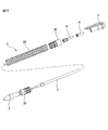
- FIG. 9 is an exploded view of the writing instrument in FIG. 8. It is a perspective view of the front joint member of the writing instrument of FIG. It is a longitudinal cross-sectional view of the front joint member of FIG. It is a perspective view of the rear joint member of the writing instrument of FIG. It is a longitudinal cross-sectional view of the rear joint member of FIG.
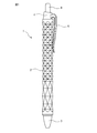
- FIG. 1 is a front view of a writing instrument 1 according to an embodiment of the present invention
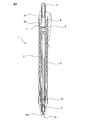
- FIG. 2 is a longitudinal sectional view of the writing instrument 1 of FIG.
- the writing instrument 1 includes a shaft cylinder 2 which is a cylindrical member formed in a cylindrical shape, a front shaft cylinder 3 which is attached to the front end portion of the shaft cylinder 2 and formed in a tapered cylinder shape, and a rear end of the shaft cylinder 2
- the rear shaft cylinder 4 is attached to the part and formed in a cylindrical shape
- the writing refill 5 is a writing body disposed in the shaft cylinder 2 and provided with a writing section 5a at one end.
- the front shaft cylinder 3 is formed with a through hole 3a for allowing the writing portion 5a of the writing refill 5 to protrude.
- the writing part 5a side is defined as the “front” side
- the opposite side of the writing part 5a is defined as the “rear” side.
- the writing refill 5 slides in the front-rear direction in the shaft cylinder 2 by a knock mechanism described later.
- the state where the writing portion 5a protrudes from the through hole 3a of the front tube 3 is referred to as a writing state (not shown), and the state where the writing portion 5a is immersed in the front shaft 3 is a non-writing state (FIG. 2). And FIG. 3).
- the rear barrel 4 is integrally formed with a clip 6 extending in the axial direction on the outer peripheral surface, so that the writing instrument 1 can be held in a pocket or a notebook.
- a plurality of cam portions 4a projecting radially inward and extending along the axial direction are formed at equal intervals along the circumferential direction.
- the rear shaft cylinder 4 is formed of a relatively hard resin material such as polycarbonate resin.
- the knock mechanism 7 includes a rotor 8 that is disposed in the rear barrel 4 so as to be movable in the front-rear direction, and an operation unit 9 that protrudes from the rear end into the rear barrel 4 and is movable in the front-rear direction. Mechanism.
- the knock mechanism 7 is urged rearward by the spring 10 together with the writing refill 5.
- the knocking operation is performed by pressing the operation unit 9 forward.
- the rotor 8 When the knocking operation is performed, the rotor 8 is pushed forward by the movement of the operation unit 9, the rotor 8 and the front end surface of the cam portion 4a of the rear barrel 4 are locked, and the writing instrument 1 maintains the writing state. .
- the knocking operation is performed again, the rotor 8 is pushed forward by the movement of the operation portion 9, and the engagement between the rotor 8 and the front end surface of the cam portion 4 a of the rear barrel 4 is released. For this reason, the knock mechanism 7 is moved backward by the urging force of the spring 10, and the writing instrument 1 is in a non-writing state (FIGS. 2 and 3).
- the writing instrument 1 is arranged such that the writing refill 5 is movable in the longitudinal direction in the shaft cylinder 2, and the writing part 5 a is projected from one end of the shaft cylinder 2 and the writing part 5 a is immersed in the shaft cylinder 2.
- the non-written state can be switched by a knock operation of the operation unit 9.
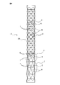
- FIG. 3 is a perspective view of the shaft tube 2 of the writing instrument 1 of FIG. 1
- FIG. 4 is a longitudinal sectional view of the shaft tube 2 of FIG. 3
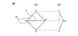
- FIG. 5 is a top view of the shaft tube 2 of FIG. 6A is a front view of the unit pattern A of the X portion of the shaft cylinder 2 of FIG. 3
- FIG. 6B is a side view of the unit pattern of the X portion of the shaft cylinder 2 of FIG.
- FIG. 7 is a front view of the unit pattern B of the Y portion of the shaft tube 2 of FIG.
- the shaft cylinder 2 has a cylindrical portion 20 in which a plurality of concave portions and convex portions are formed, and the cylindrical portion 20 has a substantially uniform radial thickness, that is, a thickness. That is, the plurality of concave portions and convex portions of the cylindrical portion 20 are formed by a combination of three-dimensional unit patterns or a pattern sequence having a substantially uniform thickness, that is, by repeating the unit patterns.
- the unit pattern basically has a rectangular outer shape.
- the unit pattern combination includes a unit pattern A (FIG. 6) indicated by the X portion, a unit pattern B indicated by the Y portion (FIG. 7), and a unit pattern C indicated by the Z portion. And are included.
- the surface area of each unit pattern increases in the order of unit pattern A, unit pattern B, and unit pattern C.
- the cylindrical portion 20 may be formed by repeating a single unit pattern.
- the lower left side of the shaft cylinder 2 is disposed on the front side of the writing instrument 1, and the upper right side is disposed on the rear side of the writing instrument 1.
- the lower part of the shaft tube 2 is disposed on the front side of the writing instrument 1, and the upper part is disposed on the rear side of the writing instrument 1.
- the unit patterns are arranged in the order of the unit pattern A, the unit pattern B, and the unit pattern C in order from the rear to the front in the cylindrical portion 20.
- the unit pattern having a larger surface area is arranged on the front side of the cylindrical part 20, and the unit pattern having a smaller surface area is arranged on the rear side of the cylindrical part 20.
- the unit pattern A will be described with reference to FIG. 6.
- the remaining two vertices c and d along the diagonal line connecting the two vertices a and b are referred to as the axis of the barrel 2 (hereinafter simply referred to as “axis”).
- the diagonal line connecting the two vertices a and b constitutes a valley fold line that forms a relative recess in the cylindrical portion 20, that is, a valley line T.
- the unit pattern A is arranged so that the line connecting the two vertices c and d is parallel to the axis. Therefore, the valley line T is disposed on a plane perpendicular to the axis.
- the unit patterns B and C have a valley line T, and diagonal lines that connect vertices that do not constitute the valley line T are arranged to be parallel to the axis.
- the same two triangle S1 patterns are arranged at the front and back with the valley line T as a boundary.
- the pattern of the triangle S1 described above with the valley line T as a boundary is disposed behind, and the pattern of the triangle S2 having a height higher than that is disposed forward.
- the pattern of the triangle S2 described above with the valley line T as a boundary is arranged in front and back.
- the cylindrical portion 20 has a configuration in which pattern rows 21 in which six identical unit patterns are arranged adjacently along the circumferential direction are densely arranged in the axial direction. That is, in the cylindrical portion 20, the two pattern rows 21 adjacent in the axial direction are out of phase with each other in the rotational direction around the axial line by a rotational angle corresponding to half the length of the valley line T. Each unit pattern of the other pattern row 21 is configured to be closely inserted between the unit patterns adjacent in the circumferential direction in the row 21. In FIGS. 3 and 4, the adjacent pattern rows 21 of the unit pattern A are indicated by bold lines for the sake of explanation.
- each unit pattern is bent along the valley line T as shown in FIG. 6B, two unit patterns adjacent between two pattern rows 21 adjacent in the axial direction are one.
- the sides are common, and the sides constitute a mountain fold line forming a relative convex portion, that is, a ridge line or a mountain line M.
- a concave portion due to the valley line T and a convex portion due to the mountain line M are formed in the cylindrical portion 20.
- the valley lines T of the unit patterns included in one pattern row 21 form a regular hexagon around the axis (FIG. 5).
- the cylindrical part 20 has substantially uniform thickness, the recessed part and the convex part are formed so that the outer peripheral surface and inner peripheral surface of the cylindrical part 20 may correspond, respectively.
- the shaft cylinder 2 is manufactured from a plastic sheet material such as polycarbonate, polypropylene, polyethylene terephthalate, or a metal sheet material such as aluminum or carbon steel. That is, the shaft cylinder 2 is formed by making cuts that are creased in advance on both surfaces of a rectangular sheet material, then welding both ends so that the whole becomes a cylindrical shape, and bending the cut along the cuts. Alternatively, the shaft cylinder 2 is formed by welding both ends of a sheet material bent in advance along the notch so that the whole becomes a cylinder. As another method, the shaft cylinder 2 is composed of two rollers that have an axis parallel to the cylinder and are arranged inside and outside the cylinder and have predetermined irregularities with respect to the sheet material formed in the cylinder shape. It is formed by making a crease while sandwiching strongly. Further, the shaft cylinder 2 may be formed by using blow molding.
- a plastic sheet material such as polycarbonate, polypropylene, polyethylene terephthalate, or a metal sheet material such as aluminum or
- the wall thickness of the formed shaft cylinder 2 is preferably less than 1 mm, for example 0.35 mm, but is not limited thereto. Moreover, since the shaft cylinder 2 is manufactured from a sheet material, the thickness of the shaft cylinder 2 is substantially uniform as a whole. Even when manufactured using other methods such as blow molding, it is desirable that the thickness of the shaft tube 2 is substantially uniform. Note that the shaft cylinder 2 is connected to the front shaft cylinder 3 and the rear shaft cylinder 4 by, for example, adhesion or welding.
- the shaft tube 2 is hard to be deformed and has a rigidity that is less likely to be deformed with respect to the force in the direction of the central axis applied when the user grips, compared to a shaft tube that has the same thickness and is formed in a cylindrical shape without unevenness. high. Further, the shaft tube 2 is thinner than a shaft tube formed in a cylindrical shape without unevenness so as to have the same rigidity with respect to the force in the direction of the central axis applied when gripping, and Light weight. Furthermore, since the shaft cylinder 2 has a regular uneven outer peripheral surface composed of a combination of polygonal three-dimensional unit patterns, there is also a decorative effect.
- the cylindrical portion 20 of the shaft cylinder 2 is constituted by the pattern rows of the unit patterns A having a relatively small surface area.
- the portion of the cylindrical portion 20 of the shaft tube 2 corresponding to the portion that the user holds at the time of writing, that is, the front portion is a pattern row of unit patterns B and a pattern row of unit patterns C having a relatively large surface area. It is composed.
- the unit pattern having a larger surface area is arranged on the front side in the cylindrical portion 20 of the shaft cylinder 2, but the unit pattern having a larger surface area may be arranged on the rear side. Good.
- a unit pattern with a larger surface area may be arrange
- Each unit pattern may be arbitrarily arranged in the axial direction regardless of the surface area of the unit pattern.
- the unit pattern of the repetitive pattern is a square, but may be a polygon such as a hexagon.
- FIG. 8 is a front view of the writing instrument 11 according to another embodiment of the present invention
- FIG. 9 is a longitudinal sectional view of the writing instrument of FIG. 8
- FIG. 10 is an exploded view of the writing instrument of FIG.
- the writing instrument 11 according to this embodiment is different from the writing instrument 1 according to the above-described embodiment in that it includes joint members such as the front joint member 30 and the rear joint member 40. Therefore, hereinafter, the writing instrument 11 according to the present embodiment will be described in detail with respect to points different from the writing instrument 1 according to the above-described embodiment, and detailed description of other points will be omitted.
- the front shaft cylinder 3 is attached to the front end portion of the shaft cylinder 2 via the front joint member 30, and the rear shaft cylinder 4 is attached to the rear end portion of the shaft cylinder 2 via the rear joint member 40. ing.
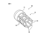
- FIG. 11 is a perspective view of the front joint member 30 of the writing instrument in FIG. 8, and FIG. 12 is a longitudinal sectional view of the front joint member 30 in FIG.
- the front joint member 30 is formed in a cylindrical shape as a whole.
- the front joint member 30 has a larger-diameter large-diameter portion 31 disposed on the front side and a smaller-diameter small-diameter portion 32 disposed on the rear side of the front joint member 30 attached to the shaft tube 2. While attached to the shaft tube 2, the large diameter portion 31 is exposed to the outside of the shaft tube 2, while the small diameter portion 32 is inserted into the front end portion of the shaft tube 2.
- the outer peripheral surface of the distal end portion of the large diameter portion 31 is formed in a tapered shape. In a state where the attachment is completed, that is, at the attachment position, the front end of the tubular portion 20 of the shaft tube 2 contacts the rear end surface of the large diameter portion 31.
- the outer peripheral surface of the small diameter portion 32 is formed in a shape complementary to the inner peripheral surface of the front end portion of the cylindrical portion 20 of the shaft tube 2 at the attachment position. That is, on the outer peripheral surface of the small-diameter portion 32, a pattern composed of a plurality of concave portions and convex portions so as to have a combination of unit patterns that is the same as or similar to the combination of unit patterns formed on the inner peripheral surface of the cylindrical portion 20.
- a portion 33 is formed. Strictly speaking, the pattern portion 33 is formed with a plurality of concave portions and convex portions so as to have a part of the same unit pattern combination as the unit pattern combination formed on the inner peripheral surface of the cylindrical portion 20. Is done.
- the small diameter portion 32 is divided by a plurality of slits 34 extending in the axial direction from the rear end face to the vicinity of the large diameter portion 31. Therefore, the pattern portion 33 differs from the combination of unit patterns formed on the inner peripheral surface of the cylindrical portion 20 by the amount missing by the slit 34 having a predetermined width in the circumferential direction, that is, the combination of unit patterns.
- a pattern corresponding to a part is configured.
- the small diameter portion 32 is defined by a slit 34 and has a plurality of projecting pieces 35 extending rearward from the rear end surface of the large diameter portion 31.
- the slit 34 divides the small diameter portion 32 equally along the circumferential direction.
- the interval in the circumferential direction of the slit 34 is preferably set so that the shape of the concave and convex portions formed on the outer surface of the projected piece 35 defined is the same in all the protruding pieces 35.
- the number of slits 34 is preferably three or more. As a result, the number of projecting pieces 35 defined is also three or more, and resistance to force applied in the radial direction from all directions is improved.
- the front joint member 30 is formed with six slits 34, thereby having six projecting pieces 35. Each of the projecting pieces 35 can be elastically deformed in the radial direction.
- the inner peripheral surface of the front joint member 30 is formed according to the outer shape of the portion of the tip barrel 3 inserted therein.
- each of the projecting pieces 35 does not need to have a substantially uniform thickness unlike the cylindrical portion 20.
- the inner surface of the projecting piece 35 is preferably complementary to the outer peripheral surface of the front shaft cylinder 3 for mounting the front shaft cylinder 3.
- a protruding portion 36 that protrudes inward in the radial direction is formed on the inner surface behind the intermediate portion of the protruding piece 35. Has been.
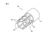
- FIG. 13 is a perspective view of the rear joint member 40 of the writing instrument of FIG. 8, and FIG. 14 is a longitudinal sectional view of the rear joint member 40 of FIG.
- the basic configuration of the rear joint member 40 is the same as that of the front joint member 30.
- the rear joint member 40 is formed in a cylindrical shape as a whole.
- the rear joint member 40 has a larger-diameter large-diameter portion 41 disposed rearward and a smaller-diameter small-diameter portion 42 disposed in front of the rear joint member 40 in a state of being attached to the shaft cylinder 2. While attached to the shaft tube 2, the large diameter portion 41 is exposed to the outside of the shaft tube 2, while the small diameter portion 42 is inserted into the front end portion of the shaft tube 2. In a state where the attachment is completed, that is, at the attachment position, the rear end of the cylindrical portion 20 of the shaft tube 2 contacts the front end surface of the large diameter portion 41.
- the outer peripheral surface of the small diameter portion 42 is formed in a shape complementary to the inner peripheral surface of the rear end portion of the tubular portion 20 of the cylindrical tube 2 at the attachment position. That is, on the outer peripheral surface of the small diameter portion 42, a pattern composed of a plurality of concave portions and convex portions so as to have the same or similar unit pattern combination as the unit pattern combination formed on the inner peripheral surface of the cylindrical portion 20. A portion 43 is formed. Strictly speaking, the pattern portion 43 is formed with a plurality of concave portions and convex portions so as to have a part of the same unit pattern combination as the unit pattern combination formed on the inner peripheral surface of the cylindrical portion 20. Is done.
- the small diameter portion 42 is divided by a plurality of slits 44 extending in the axial direction from the front end surface to the vicinity of the large diameter portion 41. Therefore, the pattern portion 43 is different from the combination of unit patterns formed on the inner peripheral surface of the cylindrical portion 20 by the amount missing by the slit 44 having a predetermined width in the circumferential direction, that is, the combination of unit patterns.
- a pattern corresponding to a part is configured.
- the small diameter portion 42 is defined by a slit 44 and has a plurality of projecting pieces 45 extending forward from the front end surface of the large diameter portion 41.
- the slit 44 divides the small diameter portion 42 evenly along the circumferential direction.
- the interval in the circumferential direction of the slits 44 is preferably set so that the shape of the concave and convex portions formed on the outer surface of the projecting piece 45 to be defined is the same in all the projecting pieces 45.
- the number of slits 44 is preferably three or more. As a result, the number of projecting pieces 45 defined is three or more, and the resistance to the force applied in the radial direction from all directions is improved.
- the rear joint member 40 is formed with six slits 44, thereby having six projecting pieces 45. Each of the projecting pieces 45 can be elastically deformed in the radial direction.
- the inner peripheral surface of the rear joint member 40 is formed in accordance with the outer shape of the portion of the rear barrel 4 inserted therein.
- each of the projecting pieces 45 does not need to have a substantially uniform thickness unlike the cylindrical portion 20.
- the inner surface of the projecting piece 45 is preferably complementary to the outer peripheral surface of the rear shaft cylinder 4 for mounting the rear shaft cylinder 4.
- a protruding portion 46 protruding radially inward is formed on the inner surface of the protruding piece 45 from the vicinity of the intermediate portion.
- the front joint member 30 and the rear joint member 40 may have the same design, and parts may be shared.
- the front joint member 30 is inserted into the front end portion of the shaft tube 2.
- the inner peripheral surface of the front end portion of the cylindrical portion 20 of the shaft cylinder 2 is formed in a shape complementary to the outer peripheral surface of the small diameter portion 32 of the front joint member 30, they are fitted to each other. Match.
- the recessed part and convex part of the internal peripheral surface of the front-end part of the cylindrical part 20 of the axial cylinder 2 and the concave part and convex part of the outer peripheral surface of the small diameter part 32 of the front joint member 30 do not correspond, these The front joint member 30 is rotated in the circumferential direction until the two coincide.
- the insertion or rotation in the circumferential direction of the front joint member 30 can be easily performed by the elastic deformation of the projecting piece 35 radially inward. That is, even if the convex part of the cylindrical part 20 and the convex part of the small diameter part 32 contact
- the rear joint member 40 is inserted into the rear end portion of the shaft tube 2, and since this is the same as the case where the front joint member 30 is inserted into the front end portion of the shaft tube 2, description thereof is omitted.
- the writing refill 5 is inserted into the shaft tube 2 from the front of the shaft tube 2, and the front shaft tube 3 is inserted into the front joint member 30.
- the front shaft cylinder 3 is fitted into the front joint member 30 by press-fitting by the projecting portion 36 inside the front joint member 30, and the attachment is completed.
- the rotor 8, the operation unit 9, and the rear shaft cylinder 4 are sequentially inserted into the shaft cylinder 2 from the rear side of the shaft cylinder 2.
- the rear shaft cylinder 4 is fitted into the rear joint member 40 by press-fitting by the projecting portion 46 inside the rear joint member 40, the attachment is completed, and the entire assembly is also completed.
- the attachment between the front barrel 3 and the front joint member 30 or the attachment between the rear barrel 4 and the rear joint member 40 may be screwing instead of press-fitting, or an adhesive may be used.
- the inner surface of the end portion of the cylindrical portion 20 needs to be smooth for fitting with the front barrel 3 or the rear barrel 4. It was.
- the writing instrument 11 according to the present embodiment it is possible to form a concavo-convex pattern up to the end of the cylindrical portion 20, that is, over the entire length. That is, the outer peripheral surface of the front joint member 30 or the rear joint member 40 receives the uneven shape of the inner peripheral surface of the tubular portion 20, and the inner peripheral surface of the front joint member 30 or the rear joint member 40 is designed freely. It becomes possible. As a result, the front barrel 3 or the rear barrel 4 can be made difficult to come off from the barrel 2.
- the front barrel 3 or the rear barrel 4 can be easily attached to the barrel 2 and, for example, the writing refill 5 can be easily replaced. As a result, the entire writing instrument can be easily assembled.
- the rear part of the front shaft cylinder 3 is formed in the same manner as the projecting piece 35, or the front part of the rear shaft cylinder 4 is formed in the same manner as the projecting piece 45 without using the front joint member 30 or the rear joint member 40. Alternatively, it may be directly attached to the cylindrical portion 20.
- Table 1 shows the weight of a shaft cylinder that is less likely to be fatigued by long-time writing operations and that has the effect of improving portability, and in which the sheet material is made of polyethylene terephthalate. It was.
- the weight of the cylindrical portion 20, that is, the shaft cylinder 2 is preferably 2 g or less per 100 mm in total length.
- the outer diameter of the cylindrical part 20 is 10 mm or more, and the full length of the cylindrical part 20 is 60 mm or more.
- one aspect of the present invention has been described using the shaft cylinder of the writing instrument.
- the present invention may be applied to a cylindrical member having another cylindrical portion such as a cap.
- one aspect of the present invention has been described using a knock-type writing instrument. May be.
Landscapes
- Pens And Brushes (AREA)
- Mechanical Pencils And Projecting And Retracting Systems Therefor, And Multi-System Writing Instruments (AREA)
Abstract
筆記具1が、複数の凹部及び凸部が形成された筒状部20を有する軸筒2を具備し、筒状部20が略均一の肉厚を有する。また、凹部及び凸部が、略均一な肉厚を有する立体的な単位パターンA、B、Cの組み合わせによって形成される。さらに、単位パターンA、B、Cの組み合わせには、異なる表面積の単位パターンA、B、Cが含まれる。単位パターンA、B、Cの表面積がより大きい方が筒状部20の前側に配置され、単位パターンA、B、Cの表面積がより小さい方が筒状部20の後側に配置される。
Description
本発明は、筆記具に関する。
従来、筆記具、例えば軸筒は、プラスチック材料を射出成形することによって製造されることが多かった。この場合、強度又は剛性を考慮すると、成形された軸筒等は、或る程度の肉厚が必要であり、その結果、筆記具の重量の増加は避けられなかった。しかしながら、長時間の筆記動作や携行性を考慮すると、筆記具は軽い方が望ましい。軽量化のため、紙製の筆記具が公知である(特許文献1)。
特許文献1に記載の筆記具は、紙という材料に起因し、剛性及び耐久性が低いという欠点がある。
本発明は、軽量で且つ剛性が高い筆記具を提供する。
本発明の一態様によれば、複数の凹部及び凸部が形成された筒状部を有する筒状部材を具備する筆記具であって、前記筒状部が略均一の肉厚を有することを特徴とする筆記具が提供される。
また、別の態様によれば、前記凹部及び前記凸部が、略均一な肉厚を有する立体的な単位パターンの組み合わせによって形成されることを特徴とする筆記具が提供される。
また、別の態様によれば、前記単位パターンの組み合わせには、異なる表面積の単位パターンが含まれることを特徴とする筆記具が提供される。
また、別の態様によれば、前記単位パターンの表面積がより大きい方が筒状部の前側に配置され、前記単位パターンの表面積がより小さい方が筒状部の後側に配置されることを特徴とする筆記具が提供される。
また、別の態様によれば、前記筒状部が、シート材から形成されることを特徴とする筆記具が提供される。
また、別の態様によれば、前記筒状部の肉厚が1mm未満であることを特徴とする筆記具が提供される。
また、別の態様によれば、前記筒状部材が、全長100mmあたり2g以下であることを特徴とする筆記具が提供される。
本発明の態様によれば、軽量で且つ剛性が高い筆記具を提供するという共通の効果を奏する。
以下、添付図面と本発明の好適な実施形態の記載から本発明を一層十分に理解できるであろう。
以下、添付図面と本発明の好適な実施形態の記載から本発明を一層十分に理解できるであろう。
以下、図面を参照しながら本発明の実施の形態を詳細に説明する。全図面に渡り、対応する構成要素には共通の参照符号を付す。
図1は、本発明の実施形態による筆記具1の正面図であり、図2は、図1の筆記具1の縦断面図である。
筆記具1は、筒状に形成された筒状部材である軸筒2と、軸筒2の前端部に取り付けられ且つ先細りの筒状に形成された先軸筒3と、軸筒2の後端部に取り付けられ且つ筒状に形成された後軸筒4と、軸筒2内に配置され且つ一端に筆記部5aを備えた筆記体である筆記リフィル5とを有している。先軸筒3は、筆記リフィル5の筆記部5aを突出させるための貫通孔3aが形成されている。なお、本明細書中では、筆記具1の軸線方向において、筆記部5a側を「前」側と規定し、筆記部5aとは反対側を「後」側と規定する。
筆記具1は、後述するノック機構によって、軸筒2内で筆記リフィル5が前後方向に摺動する。このとき、筆記部5aが先軸筒3の貫通孔3aから突出した状態を筆記状態(図示せず)と称し、筆記部5aが先軸筒3内に没入した状態を非筆記状態(図2及び図3)と称す。
後軸筒4は、外周面に、軸線方向に延びるクリップ6が一体的に形成され、筆記具1をポケットや手帳等に挟持させることが可能となっている。後軸筒4の内面には、径方向内側に突出し且つ軸線方向に沿って延びる複数のカム部4aが、周方向に沿って等間隔に形成されている。後軸筒4は、例えばポリカーボネート樹脂等といった比較的硬質の樹脂材料から形成される。
ノック機構7は、後軸筒4内に前後方向に移動可能に配置された回転子8と、後軸筒4内に後端から突出して且つ前後方向に移動可能な操作部9とを有する公知の機構である。ノック機構7は、筆記リフィル5と共にスプリング10によって後方へ付勢されている。ノック操作は、操作部9を前方に向かって押圧することによって行われる。
ノック操作を行うと、操作部9の移動によって回転子8が前方へ押圧され、回転子8と後軸筒4のカム部4aの前端面とが係止し、筆記具1は筆記状態を維持する。再びノック操作を行うと、操作部9の移動によって回転子8が前方へ押圧され、回転子8と後軸筒4のカム部4aの前端面との係止が解除される。このため、スプリング10の付勢力によってノック機構7が後方へ移動し、筆記具1は非筆記状態(図2及び図3)となる。
言い換えると、筆記具1は、筆記リフィル5が軸筒2内に前後方向に移動可能に配置され、筆記部5aが軸筒2の一端から突出した筆記状態と筆記部5aが軸筒2内に没入した非筆記状態とを、操作部9のノック操作によって切り替えられる。
図3は、図1の筆記具1の軸筒2の斜視図であり、図4は、図3の軸筒2の縦断面図であり、図5は、図3の軸筒2の上面図であり、図6の(a)は、図3の軸筒2のX部の単位パターンAの正面図であり、(b)は、図3の軸筒2のX部の単位パターンの側面図であり、図7は、図3の軸筒2のY部の単位パターンBの正面図である。
軸筒2は、複数の凹部及び凸部が形成された筒状部20を有し、筒状部20は、略均一の径方向の厚み、すなわち肉厚を有する。すなわち、筒状部20の複数の凹部及び凸部は、規則的に配列され且つ略均一な肉厚を有する立体的な単位パターンの組み合わせ又はパターン列、言い換えると単位パターンの繰り返しによって形成される。本実施形態では、単位パターンは、基本的に四角形の外形を有する。単位パターンの組み合わせには、図4において、X部で示された単位パターンA(図6)と、Y部で示された単位パターンB(図7)と、Z部で示された単位パターンCとが含まれる。各単位パターンの表面積は、単位パターンA、単位パターンB及び単位パターンCの順に大きくなる。なお、筒状部20は、単一形状の単位パターンの繰り返しによって形成してもよい。
軸筒2は、図3において、左下側が筆記具1の前側に配置され、右上側が筆記具1の後側に配置される。また、軸筒2は、図4において、下方が筆記具1の前側に配置され、上方が筆記具1の後側に配置される。各単位パターンは、筒状部20において後から前へ順に、単位パターンA、単位パターンB及び単位パターンCの順になるように配置される。すなわち、軸筒2において、単位パターンの表面積がより大きい方が筒状部20の前側に配置され、単位パターンの表面積がより小さい方が筒状部20の後側に配置される。
図6を参照しながら単位パターンAについて説明すると、2つの頂点a、bを連結する対角線に沿って、残りの2つの頂点c、dが軸筒2の軸線(以下、単に「軸線」という。)に対して径方向外方へ向かうように折り曲げられている(図6(b))。したがって、2つの頂点a、bを連結する対角線は、筒状部20において相対的な凹部を形成する谷折りの線、すなわち谷線Tを構成する。さらに、単位パターンAは、2つの頂点c、dを連結する線が、軸線と平行となるように配置される。したがって、谷線Tは、軸線に垂直な平面上に配置される。単位パターンB及びCも同様に谷線Tを有し、谷線Tを構成しない頂点を連結する対角線は、軸線と平行となるように配置される。
単位パターンAは、谷線Tを境界として同一の2つの三角形S1のパターンが前後に配置されている。また、単位パターンBは、谷線Tを境界として上述した三角形S1のパターンが後方に配置され、それよりも高さの高い三角形S2のパターンが前方に配置されている。さらに、単位パターンCは、谷線Tを境界として上述した三角形S2のパターンが前後に配置されている。
筒状部20は、6つの同一の単位パターンが周方向に沿って隣接して配置されたパターン列21が、軸線方向に亘って密に配列された構成となっている。すなわち、筒状部20において、軸線方向に隣接する2つのパターン列21は、谷線Tの長さの半分に相当する回転角だけ軸線周りの回転方向の位相が互いにずれており、一方のパターン列21において周方向に隣接する単位パターンのそれぞれの間に、他方のパターン列21の単位パターンの各々が密に入り込むようにして構成されている。なお、図3及び図4において、説明のために、単位パターンAの隣接するパターン列21を太線で示している。
各単位パターンは、図6(b)に示されるように谷線Tに沿って屈曲していることから、軸線方向に隣接する2つのパターン列21間で隣接する2つの単位パターンは、1つの辺を共通にし、且つ、その辺は相対的な凸部を形成する山折りの線、すなわち稜線又は山線Mを構成する。その結果、筒状部20には、谷線Tによる凹部と山線Mによる凸部とが形成される。1つのパターン列21に含まれる単位パターンの谷線Tは、軸線周りに正六角形を形成する(図5)。なお、筒状部20は、略均一の肉厚を有することから、筒状部20の外周面及び内周面は、それぞれ対応するように凹部及び凸部が形成されている。
軸筒2は、ポリカーボネート、ポリプロピレン、ポリエチレンテレフタラート等のプラスチックのシート材やアルミニウム、炭素鋼等の金属のシート材から製造される。すなわち、軸筒2は、矩形のシート材の両面に予め折り目となる切り込みを入れた後、全体が筒状となるように両端を溶着し、切り込みに沿って折り曲げることによって形成される。または、軸筒2は、切り込みに沿って予め折り曲げたシート材を、全体が筒状となるように両端を溶着することによって形成される。その他の方法として、軸筒2は、筒状に形成されたシート材に対して、この筒と平行な軸線を有して筒の中と外に配置され且つ所定の凹凸を有する2つのローラーで強く挟み込みながら折り目を付けることによって形成される。さらに、軸筒2は、ブロー成形を用いて形成されてもよい。
形成された軸筒2の肉厚は、1mm未満が好ましく、例えば0.35mmであるがこれに限定されない。また、軸筒2はシート材から製造されることから、軸筒2の肉厚は全体として略均一である。ブロー成形等のその他の方法を用いて製造される場合にも、軸筒2の肉厚は略均一であることが望ましい。なお、軸筒2と、先軸筒3及び後軸筒4との接続は、例えば接着又は溶着によって行われる。
軸筒2は、これと同一の肉厚で凹凸なく円筒形に形成した軸筒と比較して、使用者が把持する際に加わるその中心軸線方向に向かう力に対して、変形し難く剛性が高い。また、軸筒2は、把持する際に加わるその中心軸線方向に向かう力に対してこれと同一の剛性を有するように凹凸なく円筒形に形成した軸筒と比較して、肉厚が薄く且つ軽量である。さらに、軸筒2は、多角形の立体的な単位パターンの組み合わせからなる規則的な凹凸形状の外周面を有することから、装飾的効果もある。
単位パターンの表面積がより小さい方が、谷線T及び山線Mの各々の長さがより短くなり且つ所定表面積当たりの単位パターンがより密集し、把持する際に加わるその中心軸線方向に向かう力に対して剛性がより高い。したがって、本実施形態では、軸筒2の筒状部20の大部分を、相対的に表面積の小さい単位パターンAのパターン列で構成している。他方、使用者が筆記時に把持する箇所に相当する軸筒2の筒状部20の部分、すなわち前側の部分を、相対的に表面積の大きい単位パターンBのパターン列及び単位パターンCのパターン列で構成している。それによって、軸筒2全体の剛性は保ちつつ、使用者が筆記時に把持する箇所に適度な弾力を付与することができ、使用者の筆記のしやすさが向上する。
上述した実施形態では、軸筒2の筒状部20において、表面積のより大きい単位パターンがより前側に配置されているが、表面積のより大きい単位パターンがより後側に配置されるようにしてもよい。また、軸筒2の筒状部20において、4種類以上の単位パターンを用いて、表面積のより大きい単位パターンがより前側に配置されるようにしてもよく、表面積のより大きい単位パターンがより後側に配置されるようにしてもよく、単位パターンの表面積の大きさにかかわらず、各単位パターンが軸線方向に任意に配置されるようにしてもよい。また、上述した実施形態では、繰り返しパターンの単位パターンは、四角形であったが、六角形等その他多角形であってもよい。
図8は、本発明の別の実施形態による筆記具11の正面図であり、図9は、図8の筆記具の縦断面図であり、図10は、図8の筆記具の分解組立図である。
本実施形態による筆記具11は、前継手部材30及び後継手部材40のような継手部材を有する点で、上述した実施形態による筆記具1と異なる。したがって、以下、本実施形態による筆記具11について、上述した実施形態による筆記具1と異なる点について詳細に説明し、その他の点については詳細な説明は省略する。
筆記具11において、先軸筒3は、前継手部材30を介して軸筒2の前端部に取り付けられ、後軸筒4は、後継手部材40を介して軸筒2の後端部に取り付けられている。
図11は、図8の筆記具の前継手部材30の斜視図であり、図12は、図11の前継手部材30の縦断面図である。
前継手部材30は、全体として筒状に形成される。前継手部材30は、軸筒2に取り付けられた状態で、前方に配置されるより大径の大径部31と、その後方に配置されるより小径の小径部32とを有している。軸筒2に取り付けられた状態で、大径部31は軸筒2の外部に露出するのに対し、小径部32は軸筒2の前端部内に挿入される。大径部31の先端部の外周面は、テーパ状に形成される。取り付けが完了した状態で、すなわち取り付け位置で、軸筒2の筒状部20の前端は、大径部31の後端面に当接する。
小径部32の外周面は、取り付け位置で、軸筒2の筒状部20の前端部の内周面と相補的な形状に形成される。すなわち、小径部32の外周面には、筒状部20の内周面に形成された単位パターンの組み合わせと同一又は相似の単位パターンの組み合わせを有するように、複数の凹部及び凸部からなるパターン部33が形成される。厳密に言うと、パターン部33には、筒状部20の内周面に形成された単位パターンの組み合わせと同一の単位パターンの組み合わせの一部を有するように、複数の凹部及び凸部が形成される。
すなわち、小径部32は、その後端面から大径部31の近傍まで軸線方向に延びる複数のスリット34によって分割される。したがって、パターン部33は、周方向において所定の幅を有するスリット34によって欠損している分だけ、筒状部20の内周面に形成された単位パターンの組み合わせと異なり、すなわち単位パターンの組み合わせの一部に対応するパターンを構成する。
小径部32は、スリット34によって画成され、大径部31の後端面から後方へ延びる複数の突片35を有する。スリット34は、周方向に沿って均等に小径部32を分割する。スリット34の周方向の間隔は、画成される突片35の外面に形成された凹部及び凸部の形状がすべての突片35において同一となるように、設定されることが好ましい。また、スリット34は、3つ以上であることが好ましい。それによって画成される突片35も3つ以上となり、全方位からの径方向に加わる力に対する耐性が向上する。本実施形態では、前継手部材30は、6つのスリット34が形成され、それによって6つの突片35を有している。突片35の各々は、径方向に弾性変形可能である。
前継手部材30の内周面は、その内部に挿入される先軸筒3の部分の外形に応じて形成される。特に突片35の各々は、筒状部20のように略均一の肉厚を有する必要はない。むしろ、突片35の内面は、先軸筒3の取り付けのため、先軸筒3の外周面と相補的であることが好ましい。本実施形態においては後述するように、圧入される先軸筒3をより強固に保持するため、突片35の中間部近傍から後方の内面には、径方向内側に突出する突出部36が形成されている。
図13は、図8の筆記具の後継手部材40の斜視図であり、図14は、図13の後継手部材40の縦断面図である。後継手部材40の基本的構成は、前継手部材30と同様である。
後継手部材40は、全体として筒状に形成されている。後継手部材40は、軸筒2に取り付けられた状態で、後方に配置されるより大径の大径部41と、その前方に配置されるより小径の小径部42とを有している。軸筒2に取り付けられた状態で、大径部41は軸筒2の外部に露出するのに対し、小径部42は軸筒2の前端部内に挿入される。取り付けが完了した状態で、すなわち取り付け位置で、軸筒2の筒状部20の後端は、大径部41の前端面に当接する。
小径部42の外周面は、取り付け位置で、軸筒2の筒状部20の後端部の内周面と相補的な形状に形成される。すなわち、小径部42の外周面には、筒状部20の内周面に形成された単位パターンの組み合わせと同一又は相似の単位パターンの組み合わせを有するように、複数の凹部及び凸部からなるパターン部43が形成される。厳密に言うと、パターン部43には、筒状部20の内周面に形成された単位パターンの組み合わせと同一の単位パターンの組み合わせの一部を有するように、複数の凹部及び凸部が形成される。
すなわち、小径部42は、その前端面から大径部41の近傍まで軸線方向に延びる複数のスリット44によって分割される。したがって、パターン部43は、周方向において所定の幅を有するスリット44によって欠損している分だけ、筒状部20の内周面に形成された単位パターンの組み合わせと異なり、すなわち単位パターンの組み合わせの一部に対応するパターンを構成する。
小径部42は、スリット44によって画成され、大径部41の前端面から前方へ延びる複数の突片45を有する。スリット44は、周方向に沿って均等に小径部42を分割する。スリット44の周方向の間隔は、画成される突片45の外面に形成された凹部及び凸部の形状がすべての突片45において同一となるように、設定されることが好ましい。また、スリット44は、3つ以上であることが好ましい。それによって画成される突片45も3つ以上となり、全方位からの径方向に加わる力に対する耐性が向上する。本実施形態では、後継手部材40は、6つのスリット44が形成され、それによって6つの突片45を有している。突片45の各々は、径方向に弾性変形可能である。
後継手部材40の内周面は、その内部に挿入される後軸筒4の部分の外形に応じて形成される。特に突片45の各々は、筒状部20のように略均一の肉厚を有する必要はない。むしろ、突片45の内面は、後軸筒4の取り付けのため、後軸筒4の外周面と相補的であることが好ましい。本実施形態においては後述するように、圧入される後軸筒4をより強固に保持するため、突片45の中間部近傍から後方の内面には、径方向内側に突出する突出部46が形成されている。なお、前継手部材30及び後継手部材40を同一のデザインとして、部品を共有化してもよい。
次に、図10を参照しながら、筆記具11の組み立てについて説明する。筆記具11を組み立てるために、まず、前継手部材30を軸筒2の前端部に挿入する。上述したように、軸筒2の筒状部20の前端部の内周面は、前継手部材30の小径部32の外周面と相補的な形状に形成されていることから、両者は互いに嵌合する。なお、軸筒2の筒状部20の前端部の内周面の凹部及び凸部と、前継手部材30の小径部32の外周面の凹部及び凸部とが、一致しない場合には、これらが一致するまで、前継手部材30を周方向に回転させる。
前継手部材30の挿入又は周方向に回転は、突片35が径方向内側に弾性変形することによって容易に行うことが可能である。すなわち、挿入又は回転の過程において、筒状部20の凸部と小径部32の凸部とが当接しても、突片35が弾性変形し、互いに乗り越えることが可能となる。したがって、軸筒2の筒状部20の前端部の内周面の凹部及び凸部と、前継手部材30の小径部32の外周面の凹部及び凸部とが、互いに密着するようなクリアランスでこれらを設計することが可能となる。
次に、後継手部材40を軸筒2の後端部に挿入するが、これは、前継手部材30を軸筒2の前端部に挿入する場合と同様であるから、説明は省略する。
軸筒2に前継手部材30及び後継手部材40が取り付けられた状態で、軸筒2の前方から筆記リフィル5を軸筒2内に挿入し、先軸筒3を前継手部材30内に挿入する。先軸筒3は、前継手部材30の内部の突出部36によって、前継手部材30と圧入で以て嵌合し、取り付けが完了する。また、軸筒2の後方から、回転子8と操作部9と後軸筒4とを順に軸筒2内に挿入する。後軸筒4は、後継手部材40の内部の突出部46によって、後継手部材40と圧入で以て嵌合し、取り付けが完了し、全体の組み立ても完了する。なお、先軸筒3と前継手部材30との取り付け又は後軸筒4と後継手部材40との取り付けは、圧入の代わりに螺合であってもよく、接着剤を用いてもよい。
最初の実施形態による筆記具1では、図4に示されるように、筒状部20の端部の内面が、先軸筒3又は後軸筒4との嵌合のために平滑である必要があった。これに対し、本実施形態による筆記具11では、筒状部20の端部まで、すなわち全長に亘って凹凸形状のパターンを形成することが可能となる。すなわち、前継手部材30又は後継手部材40の外周面が、筒状部20の内周面の凹凸形状を受容し、前継手部材30又は後継手部材40の内周面は、自由に設計することが可能となる。その結果、先軸筒3又は後軸筒4が、軸筒2から外れにくくなるようにすることもできる。
その結果、先軸筒3又は後軸筒4の軸筒2に対する取り付けが容易になり、例えば、筆記リフィル5の交換が容易に行えるように設計することも可能となる。その結果として、筆記具全体としても組み立てが容易になる。
なお、先軸筒3の後部を突片35と同様に形成し、又は、後軸筒4の前部を突片45と同様に形成し、前継手部材30又は後継手部材40を用いることなく、直接的に筒状部20に取り付けるようにしてもよい。
長時間の筆記動作によっても疲労しにくく、且つ、携行性が向上するという効果の得られた軸筒であって、シート材をポリエチレンテレフタレートで製造した軸筒の重量は、表1の通りであった。筒状部20、すなわち軸筒2の重量は全長100mmあたり2g以下であることが好ましい。また、筒状部20の外径は10mm以上であり、筒状部20の全長は60mm以上であることが好ましい。

上述した実施形態では、筆記具の軸筒を用いて本発明の一態様を説明してきたが、本発明を、キャップ等その他の筒状部を有する筒状部材に適用してもよい。また、上述した実施形態では、ノック式の筆記具を用いて本発明の一態様を説明してきたが、本発明を、軸筒のような筒状部材を有するボールペン、マーキングペン、万年筆等に適用してもよい。
本発明について特定の実施形態に基づいて詳述しているが、当業者であれば本発明の請求の範囲及び思想から逸脱することなく、様々な変更、修正等が可能である。
本発明について特定の実施形態に基づいて詳述しているが、当業者であれば本発明の請求の範囲及び思想から逸脱することなく、様々な変更、修正等が可能である。
1 筆記具
2 軸筒
3 先軸筒
4 後軸筒
20 筒状部
21 パターン列
A 単位パターン
B 単位パターン
C 単位パターン
2 軸筒
3 先軸筒
4 後軸筒
20 筒状部
21 パターン列
A 単位パターン
B 単位パターン
C 単位パターン
Claims (7)
- 複数の凹部及び凸部が形成された筒状部を有する筒状部材を具備する筆記具であって、前記筒状部が略均一の肉厚を有することを特徴とする筆記具。
- 前記凹部及び前記凸部が、略均一な肉厚を有する立体的な単位パターンの組み合わせによって形成されることを特徴とする請求項1に記載の筆記具。
- 前記単位パターンの組み合わせには、異なる表面積の単位パターンが含まれることを特徴とする請求項2に記載の筆記具。
- 前記単位パターンの表面積がより大きい方が前記筒状部の前側に配置され、前記単位パターンの表面積がより小さい方が前記筒状部の後側に配置されることを特徴とする請求項3に記載の筆記具。
- 前記筒状部が、シート材から形成されることを特徴とする請求項1から4のいずれか一項に記載の筆記具。
- 前記筒状部の肉厚が1mm未満であることを特徴とする請求項1から5のいずれか一項に記載の筆記具。
- 前記筒状部材が、全長100mmあたり2g以下であることを特徴とする請求項1から6のいずれか一項に記載の筆記具。
Applications Claiming Priority (4)
| Application Number | Priority Date | Filing Date | Title |
|---|---|---|---|
| JP2014053817 | 2014-03-17 | ||
| JP2014-053817 | 2014-03-17 | ||
| JP2015-042800 | 2015-03-04 | ||
| JP2015042800A JP2015193231A (ja) | 2014-03-17 | 2015-03-04 | 筆記具 |
Publications (1)
| Publication Number | Publication Date |
|---|---|
| WO2015141589A1 true WO2015141589A1 (ja) | 2015-09-24 |
Family
ID=54144558
Family Applications (1)
| Application Number | Title | Priority Date | Filing Date |
|---|---|---|---|
| PCT/JP2015/057521 Ceased WO2015141589A1 (ja) | 2014-03-17 | 2015-03-13 | 筆記具 |
Country Status (2)
| Country | Link |
|---|---|
| JP (1) | JP2015193231A (ja) |
| WO (1) | WO2015141589A1 (ja) |
Cited By (1)
| Publication number | Priority date | Publication date | Assignee | Title |
|---|---|---|---|---|
| WO2017059949A1 (de) * | 2015-10-05 | 2017-04-13 | Staedtler Mars Gmbh & Co. Kg | Verwendung von elementen für schreib-, zeichen-, markier- und/oder malgeräte oder kosmetikgeräte oder eingabegeräte |
Citations (5)
| Publication number | Priority date | Publication date | Assignee | Title |
|---|---|---|---|---|
| JPS6211721U (ja) * | 1985-07-05 | 1987-01-24 | ||
| JPH03180228A (ja) * | 1989-08-31 | 1991-08-06 | Toyo Seikan Kaisha Ltd | 缶詰用缶及びその製造方法 |
| JPH0457733A (ja) * | 1990-06-22 | 1992-02-25 | Kuwabara Yasunaga | 金属蓋付プラスチック容器 |
| JPH11216210A (ja) * | 1998-02-02 | 1999-08-10 | Mizuno Corp | キャディバッグ用の芯材 |
| JP2004017466A (ja) * | 2002-06-17 | 2004-01-22 | Sakura Color Prod Corp | 筆記具 |
-
2015
- 2015-03-04 JP JP2015042800A patent/JP2015193231A/ja active Pending
- 2015-03-13 WO PCT/JP2015/057521 patent/WO2015141589A1/ja not_active Ceased
Patent Citations (5)
| Publication number | Priority date | Publication date | Assignee | Title |
|---|---|---|---|---|
| JPS6211721U (ja) * | 1985-07-05 | 1987-01-24 | ||
| JPH03180228A (ja) * | 1989-08-31 | 1991-08-06 | Toyo Seikan Kaisha Ltd | 缶詰用缶及びその製造方法 |
| JPH0457733A (ja) * | 1990-06-22 | 1992-02-25 | Kuwabara Yasunaga | 金属蓋付プラスチック容器 |
| JPH11216210A (ja) * | 1998-02-02 | 1999-08-10 | Mizuno Corp | キャディバッグ用の芯材 |
| JP2004017466A (ja) * | 2002-06-17 | 2004-01-22 | Sakura Color Prod Corp | 筆記具 |
Cited By (2)
| Publication number | Priority date | Publication date | Assignee | Title |
|---|---|---|---|---|
| WO2017059949A1 (de) * | 2015-10-05 | 2017-04-13 | Staedtler Mars Gmbh & Co. Kg | Verwendung von elementen für schreib-, zeichen-, markier- und/oder malgeräte oder kosmetikgeräte oder eingabegeräte |
| JP2018537307A (ja) * | 2015-10-05 | 2018-12-20 | ステッドラー マルス ゲーエムーベーハー ウント コー カーゲーSTAEDTLER Mars GmbH & Co. KG | 筆記用具、製図用具、マーキング用具、および/または絵画用具、または化粧用具、または入力機器のための要素の使用 |
Also Published As
| Publication number | Publication date |
|---|---|
| JP2015193231A (ja) | 2015-11-05 |
Similar Documents
| Publication | Publication Date | Title |
|---|---|---|
| JP5366979B2 (ja) | 鉛筆 | |
| KR102118114B1 (ko) | 인체공학적인 다목적 필기 도구 | |
| JP4555657B2 (ja) | 筆記具 | |
| JP6048866B2 (ja) | 円錐形ペン先及びこれを用いた筆記具 | |
| WO2015141589A1 (ja) | 筆記具 | |
| JP5783697B2 (ja) | 複式筆記具 | |
| JP6383528B2 (ja) | 組み立てが簡単な筆記具 | |
| US9981499B2 (en) | Ballpoint pen | |
| JP6045270B2 (ja) | リフィルを備えたボールペン | |
| JP6288924B2 (ja) | 筆記具用の部品及び該部品を有する筆記具 | |
| KR20020000474A (ko) | 필기구용 그립 및 필기구몸체 | |
| JP2023011032A (ja) | 筆記具 | |
| JP6275409B2 (ja) | クリップの軸筒への取付構造 | |
| JP5840395B2 (ja) | 筆記具の軸筒 | |
| CN105813851B (zh) | 圆珠笔 | |
| CN105189136B (zh) | 装设有握持部件的笔具的轴筒以及使用该轴筒的笔具 | |
| JP5861282B2 (ja) | 把持部材を装着した筆記具 | |
| JP4847204B2 (ja) | 複式筆記具 | |
| JP2018069553A (ja) | 筆記具 | |
| CN2664916Y (zh) | 笔杆具有拼图功能的笔具结构 | |
| JP6866186B2 (ja) | グリップ取付構造 | |
| JP5073813B2 (ja) | 筆記具のグリップ | |
| JP2024066163A (ja) | 筆記具 | |
| JP2007144701A (ja) | 筆記具の軸筒 | |
| JP4570226B2 (ja) | 軸筒の連結構造 |
Legal Events
| Date | Code | Title | Description |
|---|---|---|---|
| 121 | Ep: the epo has been informed by wipo that ep was designated in this application |
Ref document number: 15764813 Country of ref document: EP Kind code of ref document: A1 |
|
| NENP | Non-entry into the national phase |
Ref country code: DE |
|
| 122 | Ep: pct application non-entry in european phase |
Ref document number: 15764813 Country of ref document: EP Kind code of ref document: A1 |