WO2015133157A1 - 電動オイルポンプ - Google Patents
電動オイルポンプ Download PDFInfo
- Publication number
- WO2015133157A1 WO2015133157A1 PCT/JP2015/050087 JP2015050087W WO2015133157A1 WO 2015133157 A1 WO2015133157 A1 WO 2015133157A1 JP 2015050087 W JP2015050087 W JP 2015050087W WO 2015133157 A1 WO2015133157 A1 WO 2015133157A1
- Authority
- WO
- WIPO (PCT)
- Prior art keywords
- pump
- rotor
- housing
- electric oil
- bearing
- Prior art date
- Legal status (The legal status is an assumption and is not a legal conclusion. Google has not performed a legal analysis and makes no representation as to the accuracy of the status listed.)
- Ceased
Links
Images



Classifications
-
- F—MECHANICAL ENGINEERING; LIGHTING; HEATING; WEAPONS; BLASTING
- F04—POSITIVE - DISPLACEMENT MACHINES FOR LIQUIDS; PUMPS FOR LIQUIDS OR ELASTIC FLUIDS
- F04C—ROTARY-PISTON, OR OSCILLATING-PISTON, POSITIVE-DISPLACEMENT MACHINES FOR LIQUIDS; ROTARY-PISTON, OR OSCILLATING-PISTON, POSITIVE-DISPLACEMENT PUMPS
- F04C15/00—Component parts, details or accessories of machines, pumps or pumping installations, not provided for in groups F04C2/00 - F04C14/00
- F04C15/0088—Lubrication
-
- F—MECHANICAL ENGINEERING; LIGHTING; HEATING; WEAPONS; BLASTING
- F01—MACHINES OR ENGINES IN GENERAL; ENGINE PLANTS IN GENERAL; STEAM ENGINES
- F01M—LUBRICATING OF MACHINES OR ENGINES IN GENERAL; LUBRICATING INTERNAL COMBUSTION ENGINES; CRANKCASE VENTILATING
- F01M1/00—Pressure lubrication
- F01M1/02—Pressure lubrication using lubricating pumps
-
- F—MECHANICAL ENGINEERING; LIGHTING; HEATING; WEAPONS; BLASTING
- F04—POSITIVE - DISPLACEMENT MACHINES FOR LIQUIDS; PUMPS FOR LIQUIDS OR ELASTIC FLUIDS
- F04C—ROTARY-PISTON, OR OSCILLATING-PISTON, POSITIVE-DISPLACEMENT MACHINES FOR LIQUIDS; ROTARY-PISTON, OR OSCILLATING-PISTON, POSITIVE-DISPLACEMENT PUMPS
- F04C15/00—Component parts, details or accessories of machines, pumps or pumping installations, not provided for in groups F04C2/00 - F04C14/00
- F04C15/0042—Systems for the equilibration of forces acting on the machines or pump
-
- F—MECHANICAL ENGINEERING; LIGHTING; HEATING; WEAPONS; BLASTING
- F04—POSITIVE - DISPLACEMENT MACHINES FOR LIQUIDS; PUMPS FOR LIQUIDS OR ELASTIC FLUIDS
- F04C—ROTARY-PISTON, OR OSCILLATING-PISTON, POSITIVE-DISPLACEMENT MACHINES FOR LIQUIDS; ROTARY-PISTON, OR OSCILLATING-PISTON, POSITIVE-DISPLACEMENT PUMPS
- F04C2/00—Rotary-piston machines or pumps
- F04C2/08—Rotary-piston machines or pumps of intermeshing-engagement type, i.e. with engagement of co-operating members similar to that of toothed gearing
- F04C2/10—Rotary-piston machines or pumps of intermeshing-engagement type, i.e. with engagement of co-operating members similar to that of toothed gearing of internal-axis type with the outer member having more teeth or tooth-equivalents, e.g. rollers, than the inner member
- F04C2/102—Rotary-piston machines or pumps of intermeshing-engagement type, i.e. with engagement of co-operating members similar to that of toothed gearing of internal-axis type with the outer member having more teeth or tooth-equivalents, e.g. rollers, than the inner member the two members rotating simultaneously around their respective axes
-
- H—ELECTRICITY
- H02—GENERATION; CONVERSION OR DISTRIBUTION OF ELECTRIC POWER
- H02K—DYNAMO-ELECTRIC MACHINES
- H02K5/00—Casings; Enclosures; Supports
- H02K5/04—Casings or enclosures characterised by the shape, form or construction thereof
- H02K5/16—Means for supporting bearings, e.g. insulating supports or means for fitting bearings in the bearing-shields
- H02K5/173—Means for supporting bearings, e.g. insulating supports or means for fitting bearings in the bearing-shields using bearings with rolling contact, e.g. ball bearings
- H02K5/1732—Means for supporting bearings, e.g. insulating supports or means for fitting bearings in the bearing-shields using bearings with rolling contact, e.g. ball bearings radially supporting the rotary shaft at both ends of the rotor
-
- F—MECHANICAL ENGINEERING; LIGHTING; HEATING; WEAPONS; BLASTING
- F01—MACHINES OR ENGINES IN GENERAL; ENGINE PLANTS IN GENERAL; STEAM ENGINES
- F01M—LUBRICATING OF MACHINES OR ENGINES IN GENERAL; LUBRICATING INTERNAL COMBUSTION ENGINES; CRANKCASE VENTILATING
- F01M1/00—Pressure lubrication
- F01M1/02—Pressure lubrication using lubricating pumps
- F01M2001/0207—Pressure lubrication using lubricating pumps characterised by the type of pump
- F01M2001/0215—Electrical pumps
-
- F—MECHANICAL ENGINEERING; LIGHTING; HEATING; WEAPONS; BLASTING
- F01—MACHINES OR ENGINES IN GENERAL; ENGINE PLANTS IN GENERAL; STEAM ENGINES
- F01M—LUBRICATING OF MACHINES OR ENGINES IN GENERAL; LUBRICATING INTERNAL COMBUSTION ENGINES; CRANKCASE VENTILATING
- F01M1/00—Pressure lubrication
- F01M1/02—Pressure lubrication using lubricating pumps
- F01M2001/0207—Pressure lubrication using lubricating pumps characterised by the type of pump
- F01M2001/0238—Rotary pumps
-
- F—MECHANICAL ENGINEERING; LIGHTING; HEATING; WEAPONS; BLASTING
- F04—POSITIVE - DISPLACEMENT MACHINES FOR LIQUIDS; PUMPS FOR LIQUIDS OR ELASTIC FLUIDS
- F04C—ROTARY-PISTON, OR OSCILLATING-PISTON, POSITIVE-DISPLACEMENT MACHINES FOR LIQUIDS; ROTARY-PISTON, OR OSCILLATING-PISTON, POSITIVE-DISPLACEMENT PUMPS
- F04C11/00—Combinations of two or more machines or pumps, each being of rotary-piston or oscillating-piston type; Pumping installations
- F04C11/008—Enclosed motor pump units
-
- F—MECHANICAL ENGINEERING; LIGHTING; HEATING; WEAPONS; BLASTING
- F04—POSITIVE - DISPLACEMENT MACHINES FOR LIQUIDS; PUMPS FOR LIQUIDS OR ELASTIC FLUIDS
- F04C—ROTARY-PISTON, OR OSCILLATING-PISTON, POSITIVE-DISPLACEMENT MACHINES FOR LIQUIDS; ROTARY-PISTON, OR OSCILLATING-PISTON, POSITIVE-DISPLACEMENT PUMPS
- F04C15/00—Component parts, details or accessories of machines, pumps or pumping installations, not provided for in groups F04C2/00 - F04C14/00
- F04C15/0057—Driving elements, brakes, couplings, transmission specially adapted for machines or pumps
- F04C15/008—Prime movers
-
- F—MECHANICAL ENGINEERING; LIGHTING; HEATING; WEAPONS; BLASTING
- F04—POSITIVE - DISPLACEMENT MACHINES FOR LIQUIDS; PUMPS FOR LIQUIDS OR ELASTIC FLUIDS
- F04C—ROTARY-PISTON, OR OSCILLATING-PISTON, POSITIVE-DISPLACEMENT MACHINES FOR LIQUIDS; ROTARY-PISTON, OR OSCILLATING-PISTON, POSITIVE-DISPLACEMENT PUMPS
- F04C2240/00—Components
- F04C2240/30—Casings or housings
-
- F—MECHANICAL ENGINEERING; LIGHTING; HEATING; WEAPONS; BLASTING
- F04—POSITIVE - DISPLACEMENT MACHINES FOR LIQUIDS; PUMPS FOR LIQUIDS OR ELASTIC FLUIDS
- F04C—ROTARY-PISTON, OR OSCILLATING-PISTON, POSITIVE-DISPLACEMENT MACHINES FOR LIQUIDS; ROTARY-PISTON, OR OSCILLATING-PISTON, POSITIVE-DISPLACEMENT PUMPS
- F04C2240/00—Components
- F04C2240/50—Bearings
- F04C2240/52—Bearings for assemblies with supports on both sides
-
- F—MECHANICAL ENGINEERING; LIGHTING; HEATING; WEAPONS; BLASTING
- F04—POSITIVE - DISPLACEMENT MACHINES FOR LIQUIDS; PUMPS FOR LIQUIDS OR ELASTIC FLUIDS
- F04C—ROTARY-PISTON, OR OSCILLATING-PISTON, POSITIVE-DISPLACEMENT MACHINES FOR LIQUIDS; ROTARY-PISTON, OR OSCILLATING-PISTON, POSITIVE-DISPLACEMENT PUMPS
- F04C23/00—Combinations of two or more pumps, each being of rotary-piston or oscillating-piston type, specially adapted for elastic fluids; Pumping installations specially adapted for elastic fluids; Multi-stage pumps specially adapted for elastic fluids
- F04C23/008—Hermetic pumps
Definitions
- the present invention relates to an electric oil pump, and more particularly to an electric oil pump that supplies and lubricates hydraulic oil in a discharge part to a bearing part of a drive rotary shaft of the pump.
- trochoidal internal gear pumps are often used as electric oil pumps mounted on automobile transmissions.
- the pump rotor is rotated by a drive rotating shaft driven by an electric motor, and the outer rotor having the inner teeth that mesh with the outer teeth of the pump rotor is rotated, so that the inner teeth of the outer rotor and the outer teeth of the pump rotor are The volume of the plurality of volume chambers formed between the two is continuously changed to suck and discharge the working oil.
- Patent Document 1 Japanese Patent Application Laid-Open No. 2012-207638
- the electric oil pump includes a drive control unit that controls energization of the electric motor, a winding unit that generates magnetomotive force by energization from the drive control unit, a stator unit having an iron core, and a permanent magnet in the inner circumferential space of the stator unit.
- the oil groove which introduces the working oil from a discharge part in order to form an oil film in the rotation sliding surface of a drive rotating shaft is formed in the bearing part of a driving rotating shaft.
- the drive rotary shaft is pivotally supported by a cantilevered slide bearing as in Patent Document 1, and the drive rotary shaft is tilted by a gap between the inner peripheral surface of the slide bearing and the outer peripheral surface of the drive rotary shaft,
- the gap becomes non-uniform between the stator portion and the rotor portion, which causes a disturbance in the spatial magnetic flux waveform and generates a harmonic component.
- This harmonic component increases the electromagnetic excitation force in the radial direction and causes vibration, resulting in noise.
- the distance between the inner peripheral surface of the slide bearing and the outer peripheral surface of the drive rotary shaft should be as short as possible.
- New problems such as seizing due to the inability to supply oil and an increase in manufacturing cost (due to precision processing) occur.
- the drive rotary shaft is supported by a ball bearing, the tilt of the drive rotary shaft can be prevented to some extent.
- the use of a ball bearing increases the number of parts and parts costs, and the ball on the drive rotary shaft portion.
- a new problem arises that it is necessary to secure a bearing installation space. In some cases, rotation noise of the ball bearing itself (so-called squeal) may be added.
- An object of the present invention is to provide a novel electric oil pump with less noise by suppressing the inclination of the drive rotating shaft with a simple configuration.
- a feature of the present invention is that the drive rotary shaft between the rotor portion and the pump rotor is pivotally supported by a first slide bearing, and the drive rotary shaft on the tip side from the pump rotor fixing portion of the drive rotary shaft is a second slide bearing. In addition to supporting the shaft, hydraulic oil is supplied to the first slide bearing and the second slide bearing.
- the tip end side of the drive rotating portion is pivotally supported by the second slide bearing, so that the inclination of the drive rotary shaft is regulated by the inner peripheral surface of the second slide bearing, thereby preventing noise.
- the generation can be reduced.
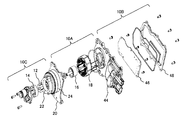
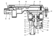
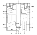
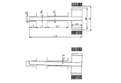
- FIG. 1 is an overall perspective view of an electric oil pump according to the present invention. It is a disassembled perspective view of the electric oil pump shown in FIG. It is a longitudinal cross-sectional view of the electric oil pump shown in FIG. It is an expanded sectional view of the A section shown in FIG. It is explanatory drawing explaining the inclination of the drive rotating shaft in patent document 1.
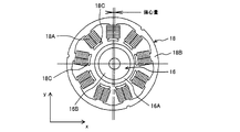
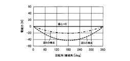
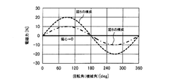
- FIG. It is explanatory drawing explaining the inclination of the drive rotating shaft shown in FIG. It is sectional drawing which shows the radial direction cross section of a rotor part and a stator part. It is explanatory drawing explaining the relationship between the rotation angle of the X direction in the radial direction cross section of a rotor part and a stator part, and electromagnetic force.
- the electric oil pump is, for example, a pump mounted for an automatic transmission of a vehicle having an idle stop function.
- This automatic transmission is a belt-type continuously variable transmission, and includes a mechanical pump that is driven by an engine.
- FIG. 1 is a perspective view showing the overall configuration of the electric oil pump
- FIG. 2 is an exploded perspective view of the electric oil pump.
- the electric oil pump 10 includes an electric motor unit 10A, a drive control unit 10B fixed adjacent to the electric motor unit 10A, and a pump unit 10C driven by the electric motor unit 10A.
- the electric motor unit 10 ⁇ / b> A includes at least a rotor unit 16 and a stator unit 18.
- the electric motor unit 10A is accommodated in an electric motor unit accommodating unit 24 provided on one side of a metal housing 20 made of, for example, an aluminum alloy.
- a pump portion storage portion 22 for storing the pump portion 10C is formed on the other side of the housing 20.
- the pump unit 10C includes at least a pump rotor 12 having an external gear and an outer rotor 14 having an internal gear.
- the pump rotor 12 and the outer rotor 14 are housed in a pump housing portion 22 provided on the other side of the housing 20.
- the drive control unit 10B includes at least a housing 44, a control board 46 accommodated in the housing 44, and a cover 48 fixed to the housing 44 so as to accommodate the control board 46.
- the electric oil pump 10 includes a pump portion 10C including a pump rotor 12 having an external gear and an outer rotor 14 having an internal gear, a rotor portion 16 coupled to the pump rotor 12, and a stator portion 18. And an electric motor unit 10A.
- a winding 18 ⁇ / b> A is wound around the stator portion 18, and this winding is drawn into the drive control circuit 42.
- pump part 10C and electric motor part 10A are accommodated in a pump part accommodating part 22 provided on one end face of the housing 20 and an electric part accommodating part 24 provided on the other end face. That is, the housing 20 has a pump portion accommodating portion 22 that rotatably accommodates the outer rotor 14 inside the one end surface side, and fixedly supports the stator portion 18 on the inner peripheral side of the opening on the other end surface side, and the rotor portion inside.
- An electric motor unit storage unit 24 for storing 16 and the like is formed, and a bracket 26 for attachment to the automatic transmission is formed outside the motor unit storage unit 24 in the axial direction.
- a first bearing portion 30 that rotatably supports a drive rotating shaft 28 that couples the pump rotor 12 and the rotor portion 16 is provided inside the housing 20.
- the first bearing portion 30 is configured to pivotally support the outer peripheral surface of the intermediate portion of the drive rotating shaft 28 on its own inner peripheral surface.
- the intermediate part means between the pump rotor 12 and the rotor part 16, and is not limited to the center of the drive rotating shaft 28.
- the 1st bearing part 30 is formed in the partition 31 which isolates between the pump part accommodating part 22 and the motor part accommodating part 24.
- the first bearing portion 30 is a slide bearing, and a first gap having a predetermined length is formed between the inner peripheral surface of the first bearing portion 30 and the outer peripheral surface of the drive rotating shaft 28. Discharge side hydraulic oil having a high pressure is introduced into the first gap via the first oil introduction passage 33. Further, a seal member 32 for sealing the drive rotary shaft 28 is provided above the drive rotary shaft 28 and the bearing portion 30.
- the pump cover 34 has a discharge port 36 extending in a cylindrical shape that communicates with the discharge port of the pump unit 10C, and a suction port 38 that communicates with the suction port of the pump unit 10C.
- a seal ring 40 is attached to the outer periphery of the distal end of the discharge port 36.
- a land portion 39 that separates the discharge port 36 and the suction port 38 of the pump cover 34 is a second bearing portion that pivotally supports the distal end portion 29 of the drive rotating shaft 28 that is located at the distal end of the fixed portion to which the pump rotor 12 is fixed. 41 is formed.
- the second bearing portion 41 is a bag-hole-like circular hole, and the tip end portion 29 of the drive rotary shaft 28 is accommodated and disposed therein.
- the second bearing portion 41 is a slide bearing, and a second gap having a predetermined length is formed between the inner peripheral surface of the second bearing portion 41 and the outer peripheral surface of the drive rotary shaft 28.
- the suction side working oil is introduced into the second gap via a second oil introduction passage (not shown).
- a portion A surrounded by an elliptical broken line is a main portion of the present embodiment, and this portion will be described in more detail with reference to FIG.
- a housing 44 constituting the drive control unit 42 is fixed to the motor unit storage unit 24 side of the housing 20 so as to seal the motor unit storage unit 24.
- the drive control unit 10B is shown, but it is the same as the drive control unit 42 shown in FIG.
- the drive control unit 42 includes a housing 44 made of synthetic resin fixed to the housing 20, a control board 46 accommodated in the housing 44, and a cover 48 made of synthetic resin fixed to the housing 44 and covering the control board 46. Has been.
- On the control board 46 an inverter circuit for supplying a controlled current to the winding 18A wound around the stator portion 18 of the electric motor portion 10A is mounted.
- a connector terminal 50 is attached between the housing 44 and the cover 48 to supply power to the control board 46.
- the winding start end portion and winding end end portion of the winding 18 ⁇ / b> A wound around the stator portion 18 constituting the electric motor portion 10 ⁇ / b> A are fixed adjacent to the electric motor portion storage portion 24.
- the drive controller 42 is connected to an input terminal (not shown) and a neutral terminal (not shown) provided in the case 44 through an insertion hole (not shown) provided in the case 44. Therefore, the drive signal controlled by the inverter circuit is supplied to the winding 18A to rotate the rotor portion 16 of the electric motor portion 10A, and finally the pump rotor 12 is rotated to perform the pump action.
- a first bearing portion 30 is formed in a part of the partition wall 31 of the housing 20.
- the first bearing portion 30 is located between the pump rotor 12 and the rotor portion 16 constituting the electric motor portion 10A, and the drive rotating shaft 28 that couples the pump rotor 12 and the rotor portion 16 is pivotally supported at this position.
- the first bearing portion 30 is a slide bearing, and the inner peripheral surface thereof and the outer peripheral surface of the drive rotary shaft 28 are configured to slide through the first gap G1. Then, the working oil is supplied from the first oil introduction passage 33 communicated with the discharge port 36 to the first gap G1.
- An oil groove 30A is formed along the drive rotation shaft 28 on the inner peripheral surface of the first bearing portion 30 (slide bearing), and hydraulic oil is supplied from the first oil introduction passage 33 to the oil groove 30A. Has been. As a result, an oil film is formed in the first gap G1 to fulfill the function of a slide bearing.
- a land portion 39 that separates the discharge port 36 and the suction port 38 of the pump cover 34 is formed with a second bearing portion 41 that pivotally supports the distal end portion 29 of the drive rotating shaft 28.
- the second bearing portion 41 is a bag hole-like circular hole, and the tip end portion 29 of the drive rotary shaft 28 is inserted and disposed therein.
- the second bearing portion 41 is a slide bearing, and a second gap G2 having a predetermined length is formed between the inner peripheral surface of the second bearing portion 41 and the outer peripheral surface of the drive rotary shaft 28. The working oil on the suction port side is introduced into the second gap G2 through the second oil introduction passage 43.
- An oil groove 41A is formed on the inner peripheral surface of the second bearing portion 41 (slide bearing) along the drive rotary shaft 28, and hydraulic oil is supplied from the second oil introduction passage 43 to the oil groove 41A. Has been. As a result, an oil film is formed in the second gap G2 to fulfill the function of a slide bearing.
- a third gap G3 is formed between the front end surface of the front end portion 29 of the drive rotating shaft 28 and the side end surface of the circular hole of the second bearing portion 41, and the operation on the suction port side is also formed in this clearance. Oil is introduced.
- the intermediate portion of the drive rotating shaft 28 and the tip portion 29 thereof are pivotally supported by the bearing portions 30 and 41 made of slide bearings. For this reason, when the drive rotary shaft 28 is tilted about the vicinity of the first bearing portion 30, the tip end portion 29 of the drive rotary shaft 28 comes into contact with the inner peripheral surface of the second bearing portion 41.
- the inclination of 28 is regulated.
- the fluctuation of the gap (air gap) between the stator portion 18 and the rotor portion 16 can be made smaller than the conventional one, and the increase in the radial electromagnetic excitation force can be reduced to reduce the noise. Can be suppressed.
- the configuration can be simplified. Since the increase in the number of parts and the part cost can be suppressed as compared with the case where a bearing such as a ball bearing is used, the product unit price can be reduced along with the simplification of the configuration.
- the inner peripheral diameter d1 and the bearing length L1 of the slide bearing between the pump rotor 12 and the rotor 16, the outer peripheral diameter ds of the drive shaft 28, the outer peripheral diameter dm of the rotor 16 part, and the inner peripheral diameter of the stator part 18 dc has the same length.
- the inner peripheral diameter d2 and the bearing length L2 are used in the second embodiment of the slide bearing constituting the bearing portion 41.
- the length between the slide bearings (the portion where the pump rotor is disposed) is L3.
- FIG. 5 shows the case of the electric oil pump disclosed in Patent Document 1.
- FIG. 6 shows the case of the electric oil pump according to this embodiment.
- the apparent bearing length is (L1 + L2 + L3), which is longer than the conventional bearing length L1 shown in FIG. For this reason, the inclination of the drive rotating shaft 28 becomes ⁇ 2 ⁇ 1, and it can be seen that the present embodiment can regulate the inclination to be smaller.
- the minimum value AGmin of the air gap between the stator portion 18 and the rotor portion 16 is as follows by the inclinations ⁇ 1 and ⁇ 2.
- ⁇ 1 CLs / L1-dm (1-cos ⁇ 1)
- ⁇ 2 CLs / (L1 + L2 + L3) ⁇ dm (1 ⁇ cos ⁇ 2)
- a method of increasing the bearing length of the slide bearing shown in FIG. 5 to reduce the inclination of the drive rotating shaft 28 is also conceivable, but in this case, the length between the rotor portion 18 and the pump rotor 12 is reduced.
- the axial shape of the entire electric oil pump becomes longer as the length increases. This is not a good idea considering that the electric oil pump is housed in an engine room with a limited installation space.
- the portion L3 to which the pump rotor 12 of the drive rotary shaft 28 is fixed is used as an apparent bearing length, so that the bearing length can be increased without increasing the overall shape of the electric oil pump. is there. Therefore, as shown in FIG. 6, the inclination of the drive rotating shaft 28 can be reduced, and as a result, the fluctuation of the air gap between the rotor portion 16 and the stator portion 18 can be reduced.
- the bearing length is set as a configuration in which the intermediate portion of the drive rotating shaft 28 and the tip portion 29 of the pump rotor 12 are supported by the bearing portions 30 and 41 made of slide bearings with the pump rotor 12 interposed therebetween.
- the apparently larger configuration when the drive rotary shaft 28 is tilted about the vicinity of the first bearing portion 30, the tip end portion 29 of the drive rotary shaft 28 comes into contact with the inner peripheral surface of the second bearing portion 41. The inclination of 28 is restricted to be small.
- the fluctuation (air gap nonuniformity) of the gap (air gap) between the stator portion 18 and the rotor portion 16 can be made smaller than that of the conventional one, and the increase in the radial electromagnetic excitation force can be reduced to reduce noise. Can be suppressed.
- FIG. 7 shows a cross section of the starter portion 18 and the rotor portion 16, and shows a state where the rotor portion 16 is eccentric.
- the iron core 18B constituting the stator portion 18 is composed of laminated silicon steel plates and the like, and has nine salient pole portions 18C extending radially toward the inner peripheral side.
- a bobbin portion made of an insulating synthetic resin is provided around the salient pole portion, and this bobbin portion has a function of ensuring insulation between the winding 18A wound around itself and the salient pole portion 18C.
- the bobbin portion covering the salient pole portion 18C is wound with the winding 18A of each phase, and is usually arranged in the order of the U phase, the V phase, and the W phase.
- the windings of each phase are divided into three pieces, nine salient pole portions 18C are formed on the iron core 18B, and these nine salient pole portions 18C are arranged adjacent to each other. Yes.
- the rotor portion 16 is disposed on the inner periphery of the salient pole portion 18C, and the permanent magnet 16B is disposed inside the back yoke 16A.
- FIG. 7 shows a state in which the back yoke 16 ⁇ / b> A of the rotor portion 16 is eccentric in the X direction between the salient pole portion 18 ⁇ / b> D of the stator portion 18 and the air gap is made nonuniform due to the inclination of the drive rotation shaft 28. Is shown.
- FIG. 9 shows a change in the electromagnetic force in the Y direction during one rotation of the rotor unit 16.
- the electromagnetic force greatly fluctuates in the conventional configuration shown in FIG.
- the fluctuation of the electromagnetic force is reduced.
- the fluctuation of the electromagnetic force in the Y direction becomes a secondary rotation vibration and the sound becomes louder.
- the amount of eccentricity of the rotor portion 16 can be reduced, the fluctuation of the electromagnetic force can also be reduced, and as a result, the operating noise can be suppressed.
- the intermediate portion of the drive rotary shaft 28 and the tip portion 29 are supported by the bearing portions 30 and 41 made of slide bearings. For this reason, when the drive rotary shaft 28 is tilted about the vicinity of the first bearing portion 30, the tip end portion 29 of the drive rotary shaft 28 comes into contact with the inner peripheral surface of the second bearing portion 41.
- the inclination of 28 is regulated.
- the fluctuation of the gap (air gap) between the stator portion 18 and the rotor portion 16 can be made smaller than the conventional one, and the increase in the radial electromagnetic excitation force can be reduced to reduce the noise. Can be suppressed.
- the portion L3 where the pump rotor 12 of the drive rotary shaft 28 is fixed is used as an apparent bearing length without increasing the overall shape of the electric oil pump.
- the bearing length can be increased.
- the configuration can be simplified. Since the increase in the number of parts and the part cost can be suppressed as compared with the case where a bearing such as a ball bearing is used, the unit price of the product can be reduced with simplification of the configuration.
- the inner peripheral diameter of the second bearing portion 41 formed on the land portion 39 of the pump cover 34 and the inner peripheral diameter of the first bearing portion 30 formed on the partition wall 31 of the housing 20 are the same. However, if the inner peripheral diameter of the second bearing portion 41 is reduced, the distance of the gap G2 is shortened, so that the inclination of the drive rotating shaft 28 can be further reduced.
- the second bearing portion 41 is a bag hole-like circular hole, the temperature of the working oil is likely to rise. As a result, the viscosity of the working oil can be lowered, so that the working oil can easily flow even in a narrow passage.
- the configuration is advantageous when the inner peripheral diameter of the second bearing portion 41 is reduced to shorten the distance of the gap G2.
- the drive rotary shaft 28 is pivotally supported by the first bearing 30 and the second bearing 41, the load on the bearing can be reduced. This is an effect of extending the bearing length, but this makes it possible to use an inexpensive metal material with low hardness and to expand the degree of freedom of material selection. As a result, it is possible to expect to lower the unit price of the electric oil pump.
- the first bearing portion 30 is formed in the housing 20, and the second bearing portion 41 is formed in the pump cover 34.
- the drive rotating shaft 28 may be assembled
- the drive rotation shaft 28 is tilted, a phenomenon that the operation noise increases as described above occurs. Therefore, it is important to assemble the pump cover 34 and the housing 20 in a proper state, and this positioning mechanism will be described below.
- FIG. 10 shows an embodiment in which a positioning protrusion 51 formed as an arc-shaped protrusion is provided on the surface of the pump cover 34 that contacts the housing 20.
- the arc-shaped positioning projection 51 is brought into inlay engagement with the wall surface of the arc-shaped positioning hole 52 formed in the pump housing portion 22 in which the outer rotor 14 of the housing 20 is housed, so that the pump cover 34 and the housing 20 are engaged.
- FIG. 11 shows an embodiment in which at least two positioning pins 53 are provided on the surface of the pump cover 34 that contacts the housing 20.
- the positioning pin 53 is a positioning mechanism that is inserted into two positioning holes 54 formed on the surface of the housing 20 that contacts the pump cover 34 to position the pump cover 34 and the housing 20. According to such a structure, it can prevent that a position shifts between the 1st bearing part 30 and the 2nd bearing part 41, and can prevent that the drive rotating shaft 28 is assembled
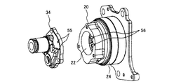
- FIG. 12 shows an embodiment in which at least two positioning holes 55 are provided on the surface of the pump cover 34 that contacts the housing 20.
- the positioning hole 55 is a positioning mechanism for positioning the pump cover 34 and the housing 20 by inserting two positioning pins 56 formed on the surface of the housing 20 that contacts the pump cover 34. According to such a structure, it can prevent that a position shifts between the 1st bearing part 30 and the 2nd bearing part 41, and can prevent that the drive rotating shaft 28 is assembled
- the feature of the present invention is that the drive rotation shaft between the rotor portion and the pump rotor is pivotally supported by the first slide bearing, and the drive rotation shaft on the tip side from the pump rotor fixing portion of the drive rotation shaft is arranged.
- the second sliding bearing is pivotally supported, and hydraulic oil is supplied to the first sliding bearing and the second sliding bearing.
- the tip end side of the drive rotary part is pivotally supported by the second slide bearing, the inclination of the drive rotary shaft is regulated by the inner peripheral surface of the second slide bearing, thereby generating noise. Can be reduced. Further, since the slide bearing is only formed on the housing and the pump cover, the configuration is simplified.
Landscapes
- Engineering & Computer Science (AREA)
- Mechanical Engineering (AREA)
- General Engineering & Computer Science (AREA)
- Power Engineering (AREA)
- Details And Applications Of Rotary Liquid Pumps (AREA)
- Rotary Pumps (AREA)
Abstract
Description
θ2=tan-1(C/(L1+L2+L3))……(2)となる。
δ2=CLs/(L1+L2+L3)-dm(1-cosθ2)
とすると、δ1>δ2のときにAG1min<AG2minとなり、本実施例の方がエアギャップの変動が小さくなることがわかる。したがって、作動音の原因となるエアギャップの不均一化を抑制できるので、これに基づく作動音を小さくすることができるようになる。
Claims (8)
- ハウジングに形成されたポンプ収納部に収納されたポンプロータとアウタロータとから構成されるポンプ部と、永久磁石を備えるロータ部と鉄心と巻線を備えるステータ部から構成される電動機部と、前記ポンプロータと前記ロータ部を結合する駆動回転軸と、前記駆動回転軸を前記ポンプロータと前記ロータ部の間で軸支するすべり軸受よりなる第1の軸受部と、前記第1の軸受部に作動オイルを供給する第1の作動オイル導入通路と、前記ポンプ部と連通された吐出ポートと吸入ポートを備え前記ポンプ部を覆うように前記ハウジングに固定されたポンプカバーより構成され、前記ロータを回転させて前記ポンプ部を駆動する電動オイルポンプにおいて、
前記駆動回転軸の前記ポンプロータが固定された部分より先端側の前記駆動回転軸の先端部を前記ポンプカバーに設けたすべり軸受よりなる第2の軸受部で軸支すると共に、前記第2の軸受部に作動オイルを供給する第2の作動オイル導入通路を設けたことを特徴とする電動オイルポンプ。 - 請求項1に記載の電動オイルポンプにおいて、
前記第1の軸受部の内周面には前記第1の作動オイル導入通路に接続された油溝が形成され、前記第2の軸受部の内周面には前記第2の作動オイル導入通路に接続された油溝が形成されていることを特徴とする電動オイルポンプ。 - 請求項2に記載の電動オイルポンプにおいて、
前記第1の作動オイル導入通路は前記吐出ポートから作動オイルが供給され、前記第2の作動オイル導入通路は前記吸入ポートから作動オイルが供給されていることを特徴とする電動オイルポンプ。 - 請求項1乃至請求項3のいずれかに記載の電動オイルポンプにおいて、
前記第2の軸受部は袋孔状の円形孔から形成され、この円形孔に前記駆動回転軸の前記先端部が収納、配置されていることを特徴とする電動オイルポンプ。 - 請求項1乃至請求項4のいずれかに記載の電動オイルポンプにおいて、
前記第2の軸受部の内周径は、前記駆動回転軸の外周径より長く、前記第1の軸受部の内周径より短いことを特徴とする電動オイルポンプ。 - 請求項1乃至請求項5のいずれかに記載の電動オイルポンプにおいて、
前記ポンプカバーと前記ハウジングの間には、前記第1の軸受部と前記第2の軸受部の位置を決める位置決め機構が設けられていることを特徴とする電動オイルポンプ。 - 請求項6に記載の電動オイルポンプにおいて、
前記位置決め機構は、前記ポンプカバーの前記ハウジングと接触する面に円弧状の突起として形成された位置決め突起部と、前記ハウジングのポンプ収納部に形成され前記位置決め突起部が当接する円弧状の位置決め孔より構成されていることを特徴とする電動オイルポンプ。 - 請求項6に記載の電動オイルポンプにおいて、
前記位置決め機構は、前記ポンプカバーの前記ハウジングと接触する面に植立した位置決めピンと、前記ハウジングの前記ポンプカバーと接触する面に形成され前記位置決めピンが挿入される位置決め孔より構成されているか、或いは、前記ハウジングの前記ポンプカバーと接触する面に植立した位置決めピンと、前記ポンプカバーの前記ハウジングと接触する面に形成され前記位置決めピンが挿入される位置決め孔より構成されていることを特徴とする電動オイルポンプ。
Priority Applications (3)
| Application Number | Priority Date | Filing Date | Title |
|---|---|---|---|
| CN201580000208.6A CN105229306B (zh) | 2014-03-04 | 2015-01-06 | 电动油泵 |
| DE112015000054.2T DE112015000054B4 (de) | 2014-03-04 | 2015-01-06 | Elektrische Ölpumpe |
| US14/773,548 US9683567B2 (en) | 2014-03-04 | 2015-01-06 | Electric oil pump |
Applications Claiming Priority (2)
| Application Number | Priority Date | Filing Date | Title |
|---|---|---|---|
| JP2014041348A JP6227445B2 (ja) | 2014-03-04 | 2014-03-04 | 電動オイルポンプ |
| JP2014-041348 | 2014-03-04 |
Publications (1)
| Publication Number | Publication Date |
|---|---|
| WO2015133157A1 true WO2015133157A1 (ja) | 2015-09-11 |
Family
ID=54054969
Family Applications (1)
| Application Number | Title | Priority Date | Filing Date |
|---|---|---|---|
| PCT/JP2015/050087 Ceased WO2015133157A1 (ja) | 2014-03-04 | 2015-01-06 | 電動オイルポンプ |
Country Status (5)
| Country | Link |
|---|---|
| US (1) | US9683567B2 (ja) |
| JP (1) | JP6227445B2 (ja) |
| CN (1) | CN105229306B (ja) |
| DE (1) | DE112015000054B4 (ja) |
| WO (1) | WO2015133157A1 (ja) |
Families Citing this family (11)
| Publication number | Priority date | Publication date | Assignee | Title |
|---|---|---|---|---|
| DE102016002336B4 (de) * | 2016-02-29 | 2021-12-09 | Volkswagen Aktiengesellschaft | Kompakte Baueinheit für ein Kraftfahrzeug, insbesondere eine als Pumpenantrieb ausgeführte kompakte Baueinheit aufweisend einen Elektromotor und ein Steuergerät, beziehungsweise Getriebegehäuse oder Tankgehäuse für ein Kraftfahrzeug mit der zuvor genannten kompakten Baueinheit |
| US11286927B2 (en) * | 2017-03-23 | 2022-03-29 | Nidec Tosok Corporation | Pump device |
| CN109113988B (zh) * | 2017-06-26 | 2020-10-23 | 比亚迪股份有限公司 | 电动油泵总成、转向系统和润滑系统 |
| CN109113954B (zh) * | 2017-06-26 | 2020-10-23 | 比亚迪股份有限公司 | 电动油泵总成、转向系统和润滑系统 |
| DE102017219004A1 (de) * | 2017-10-24 | 2019-04-25 | Brose Fahrzeugteile GmbH & Co. Kommanditgesellschaft, Würzburg | Elektromotorische Ölpumpe mit Rückschlagventil |
| KR20190132020A (ko) * | 2018-05-18 | 2019-11-27 | 현대자동차주식회사 | 내측링을 구비한 오일펌프 |
| US11398762B2 (en) * | 2018-09-28 | 2022-07-26 | Nidec Tosok Corporation | Electric pump device |
| JP7490366B2 (ja) * | 2020-01-06 | 2024-05-27 | 住友重機械工業株式会社 | アクチュエータ |
| CN113904503B (zh) * | 2020-07-06 | 2023-03-10 | 上海汽车集团股份有限公司 | 集成式电子油泵总成 |
| WO2022048364A1 (zh) * | 2020-09-03 | 2022-03-10 | 安徽威灵汽车部件有限公司 | 泵装置和车辆 |
| WO2025199813A1 (zh) * | 2024-03-27 | 2025-10-02 | 舍弗勒技术股份两合公司 | 电动油泵 |
Citations (3)
| Publication number | Priority date | Publication date | Assignee | Title |
|---|---|---|---|---|
| JP2000145663A (ja) * | 1998-11-11 | 2000-05-26 | Shimadzu Corp | ギヤポンプ |
| JP2006316674A (ja) * | 2005-05-11 | 2006-11-24 | Hitachi Powdered Metals Co Ltd | トロコイドポンプ |
| JP2013199849A (ja) * | 2012-03-23 | 2013-10-03 | Hitachi Automotive Systems Ltd | 内接歯車ポンプ |
Family Cites Families (10)
| Publication number | Priority date | Publication date | Assignee | Title |
|---|---|---|---|---|
| JPS62111183A (ja) * | 1985-11-08 | 1987-05-22 | Toshiba Corp | 回転式ポンプ |
| EP2282059B1 (en) * | 2004-07-30 | 2017-01-25 | Pulsafeeder, Inc. | Gear pump with magnetic coupling assembly |
| JP4856137B2 (ja) * | 2008-09-08 | 2012-01-18 | 日立オートモティブシステムズ株式会社 | ギヤポンプ |
| US8182235B2 (en) * | 2008-11-25 | 2012-05-22 | Toyota Motor Engineering & Manufacturing North America, Inc. | Multi-drive fluid pump |
| CN102246397B (zh) * | 2008-12-11 | 2014-05-07 | 松下电器产业株式会社 | 电动机和具备该电动机的电设备 |
| JP4918936B2 (ja) * | 2009-12-03 | 2012-04-18 | 株式会社デンソー | 電動ポンプ |
| DE102010005072A1 (de) * | 2010-01-13 | 2011-07-14 | Eckerle Industrie-Elektronik GmbH, 76316 | Innenzahnradpumpe mit druckentlastetem Wellendichtring |
| JP5089729B2 (ja) * | 2010-05-31 | 2012-12-05 | ジヤトコ株式会社 | オイルポンプ装置 |
| JP5502008B2 (ja) * | 2011-03-30 | 2014-05-28 | 日立オートモティブシステムズ株式会社 | 内接歯車ポンプ |
| JP5511770B2 (ja) * | 2011-11-08 | 2014-06-04 | 三菱電機株式会社 | 電動ポンプ、及び電動ポンプの製造方法 |
-
2014
- 2014-03-04 JP JP2014041348A patent/JP6227445B2/ja not_active Expired - Fee Related
-
2015
- 2015-01-06 CN CN201580000208.6A patent/CN105229306B/zh not_active Expired - Fee Related
- 2015-01-06 WO PCT/JP2015/050087 patent/WO2015133157A1/ja not_active Ceased
- 2015-01-06 DE DE112015000054.2T patent/DE112015000054B4/de not_active Expired - Fee Related
- 2015-01-06 US US14/773,548 patent/US9683567B2/en not_active Expired - Fee Related
Patent Citations (3)
| Publication number | Priority date | Publication date | Assignee | Title |
|---|---|---|---|---|
| JP2000145663A (ja) * | 1998-11-11 | 2000-05-26 | Shimadzu Corp | ギヤポンプ |
| JP2006316674A (ja) * | 2005-05-11 | 2006-11-24 | Hitachi Powdered Metals Co Ltd | トロコイドポンプ |
| JP2013199849A (ja) * | 2012-03-23 | 2013-10-03 | Hitachi Automotive Systems Ltd | 内接歯車ポンプ |
Also Published As
| Publication number | Publication date |
|---|---|
| US9683567B2 (en) | 2017-06-20 |
| CN105229306A (zh) | 2016-01-06 |
| JP6227445B2 (ja) | 2017-11-08 |
| DE112015000054T5 (de) | 2016-01-14 |
| CN105229306B (zh) | 2017-10-13 |
| JP2015166570A (ja) | 2015-09-24 |
| US20160076539A1 (en) | 2016-03-17 |
| DE112015000054B4 (de) | 2016-11-03 |
Similar Documents
| Publication | Publication Date | Title |
|---|---|---|
| JP6227445B2 (ja) | 電動オイルポンプ | |
| KR102631733B1 (ko) | 전기 모터 구동식 액체 펌프 | |
| JP4918936B2 (ja) | 電動ポンプ | |
| JP2007129847A (ja) | 電動機およびそれを用いた燃料ポンプ | |
| JP2012189015A (ja) | 電動ポンプユニット | |
| JP5502008B2 (ja) | 内接歯車ポンプ | |
| JP2014066179A (ja) | 電動オイルポンプ | |
| JP6385762B2 (ja) | 電動オイルポンプ | |
| WO2020240735A1 (ja) | 電動機及びそれを備えた圧縮機 | |
| JP2025514296A (ja) | ポンプ | |
| JP2016053309A (ja) | 自動変速機と組み合わされる電動オイルポンプ | |
| JP6133735B2 (ja) | 電動オイルポンプ | |
| JP6819392B2 (ja) | 電動オイルポンプ装置及び電動オイルポンプ用ベースプレート | |
| JP6133734B2 (ja) | 電動オイルポンプ | |
| JP2005207320A (ja) | 燃料ポンプ | |
| JP2012120395A (ja) | モータ、および、これを用いた電動ポンプ | |
| JP2014107951A (ja) | モータ | |
| JP2017096099A (ja) | 電動ポンプ及び自動変速機と組み合わされる電動オイルポンプ | |
| KR20220045754A (ko) | 전동 펌프 | |
| JP2004360678A (ja) | 燃料ポンプ | |
| KR102405642B1 (ko) | 전동 펌프 | |
| JP2013072370A (ja) | オイルポンプ装置 | |
| JP2019173658A (ja) | 電動圧縮機 | |
| JP6418059B2 (ja) | 燃料ポンプ | |
| JP2024524449A (ja) | ポンプ |
Legal Events
| Date | Code | Title | Description |
|---|---|---|---|
| WWE | Wipo information: entry into national phase |
Ref document number: 201580000208.6 Country of ref document: CN |
|
| WWE | Wipo information: entry into national phase |
Ref document number: 14773548 Country of ref document: US |
|
| 121 | Ep: the epo has been informed by wipo that ep was designated in this application |
Ref document number: 15758106 Country of ref document: EP Kind code of ref document: A1 |
|
| WWE | Wipo information: entry into national phase |
Ref document number: 1120150000542 Country of ref document: DE Ref document number: 112015000054 Country of ref document: DE |
|
| 122 | Ep: pct application non-entry in european phase |
Ref document number: 15758106 Country of ref document: EP Kind code of ref document: A1 |