WO2015125396A1 - 測定装置 - Google Patents
測定装置 Download PDFInfo
- Publication number
- WO2015125396A1 WO2015125396A1 PCT/JP2014/083758 JP2014083758W WO2015125396A1 WO 2015125396 A1 WO2015125396 A1 WO 2015125396A1 JP 2014083758 W JP2014083758 W JP 2014083758W WO 2015125396 A1 WO2015125396 A1 WO 2015125396A1
- Authority
- WO
- WIPO (PCT)
- Prior art keywords
- unit
- fingertip
- measurement
- fluorescence
- outer edge
- Prior art date
- Legal status (The legal status is an assumption and is not a legal conclusion. Google has not performed a legal analysis and makes no representation as to the accuracy of the status listed.)
- Ceased
Links
Images








Classifications
-
- A—HUMAN NECESSITIES
- A61—MEDICAL OR VETERINARY SCIENCE; HYGIENE
- A61B—DIAGNOSIS; SURGERY; IDENTIFICATION
- A61B5/00—Measuring for diagnostic purposes; Identification of persons
- A61B5/68—Arrangements of detecting, measuring or recording means, e.g. sensors, in relation to patient
- A61B5/6801—Arrangements of detecting, measuring or recording means, e.g. sensors, in relation to patient specially adapted to be attached to or worn on the body surface
- A61B5/6843—Monitoring or controlling sensor contact pressure
-
- A—HUMAN NECESSITIES
- A61—MEDICAL OR VETERINARY SCIENCE; HYGIENE
- A61B—DIAGNOSIS; SURGERY; IDENTIFICATION
- A61B5/00—Measuring for diagnostic purposes; Identification of persons
- A61B5/145—Measuring characteristics of blood in vivo, e.g. gas concentration or pH-value ; Measuring characteristics of body fluids or tissues, e.g. interstitial fluid or cerebral tissue
- A61B5/14546—Measuring characteristics of blood in vivo, e.g. gas concentration or pH-value ; Measuring characteristics of body fluids or tissues, e.g. interstitial fluid or cerebral tissue for measuring analytes not otherwise provided for, e.g. ions, cytochromes
-
- A—HUMAN NECESSITIES
- A61—MEDICAL OR VETERINARY SCIENCE; HYGIENE
- A61B—DIAGNOSIS; SURGERY; IDENTIFICATION
- A61B5/00—Measuring for diagnostic purposes; Identification of persons
- A61B5/145—Measuring characteristics of blood in vivo, e.g. gas concentration or pH-value ; Measuring characteristics of body fluids or tissues, e.g. interstitial fluid or cerebral tissue
- A61B5/1455—Measuring characteristics of blood in vivo, e.g. gas concentration or pH-value ; Measuring characteristics of body fluids or tissues, e.g. interstitial fluid or cerebral tissue using optical sensors, e.g. spectral photometrical oximeters
-
- A—HUMAN NECESSITIES
- A61—MEDICAL OR VETERINARY SCIENCE; HYGIENE
- A61B—DIAGNOSIS; SURGERY; IDENTIFICATION
- A61B5/00—Measuring for diagnostic purposes; Identification of persons
- A61B5/68—Arrangements of detecting, measuring or recording means, e.g. sensors, in relation to patient
- A61B5/6801—Arrangements of detecting, measuring or recording means, e.g. sensors, in relation to patient specially adapted to be attached to or worn on the body surface
- A61B5/6813—Specially adapted to be attached to a specific body part
- A61B5/6825—Hand
- A61B5/6826—Finger
Definitions
- the present invention relates to a measuring apparatus for measuring the amount of the fluorescent substance based on the intensity of fluorescence generated from the fluorescent substance in the living body.
- Diabetes is a disorder of eating habits and lifestyle habits, the effects of secretions from fat cells due to obesity, oxidative stress, pancreatic function decline, lack of insulin to control blood sugar levels, and reduced efficacy It develops by. Symptoms such as increased frequency and volume of urination and thirst appear when you have diabetes. However, if you have only this, there is no subjective symptom of illness, and it is almost always detected by examinations at hospitals. This is why there are many “silent” diabetics.
- AGEs Advanced Glycation Endproducts; late glycation products. Is done.
- AGEs are end products formed by non-enzymatic glycosylation reaction (Maillard reaction) of proteins. They are yellowish brown, fluorescing substances that bind to nearby proteins to form crosslinks. It has properties.
- AGEs are said to cause arteriosclerosis by depositing and invading blood vessel walls, acting on macrophages that are part of the immune system, releasing cytokines that are a type of protein, and causing inflammation. ing.
- excitation light is irradiated on the skin of the forearm, fluorescence spectra from AGEs bound to skin collagen are measured, and AGEs are monitored by comparing the measured fluorescence spectrum with a predetermined model. . Thereby, the data of AGEs are acquired, without invading.
- Patent Document 2 describes a detection device that specifies an optimum position of a relative position between a subject and a light receiving unit that receives fluorescence emitted from the subject based on the received light intensity received by the light receiving unit. Yes.
- Patent Document 3 describes a device that monitors AGEs by wearing it on the earlobe. By making a relatively small part such as an earlobe a measurement target part in the human body, the apparatus can be miniaturized.
- examples of a measuring apparatus that uses a relatively small part in the human body as a measurement target part include the techniques described in Patent Documents 4 to 6. These are devices that measure blood oxygen saturation or pulse waves using a fingertip as a measurement target site.
- the AGEs are monitored on the table by placing the forearm that is the measurement target part.
- the intensity of the measured fluorescence spectrum (fluorescence intensity) is not stable because the forearm is not fixed. There is a problem.
- the measurement target parts such as the subject, the earlobe, and the finger are fixed to some extent.
- the immobilization is not sufficient for immobilizing the measurement target site, and there still remains a problem that measurement results such as fluorescence intensity are not stable.
- the present invention has been made in view of the above problems, and an object thereof is to realize a measuring apparatus capable of obtaining a stable measurement result.
- a measurement apparatus is based on the intensity of fluorescence generated from a fluorescent substance in the living body excited by excitation light irradiated to a measurement target site in the living body.
- the above-mentioned mounting part and the above-mentioned clamping part provided on either the above-mentioned mounting part and the above-mentioned clamping part, and the above-mentioned mounting part and the above-mentioned clamping part.
- a light receiving unit, and a fixing force supply unit that supplies a force capable of fixing a relative positional relationship between the measurement target site and the light receiving unit to the measurement target site via the clamping unit.
- the intensity of fluorescence generated from the measurement target site depends on the distance between the blood vessel position of the measurement target site where the fluorescent substance is present and the light receiving unit. For this reason, if the measurement target region is not sufficiently fixed, the distance between the blood vessel position and the light receiving unit changes due to the elasticity of the measurement target region, and the fluorescence intensity is not stable.
- part and the said light-receiving part is supplied to a measurement object site
- the placement unit and the sandwiching unit have opposing surfaces that face each other in a state where the measurement target part is sandwiched, and the light receiving unit is the placement unit described above. Or you may protrude from the opposing surface of the said clamping part.
- the tip of the light receiving portion can be strongly pressed against the measurement target site. That is, the measurement target part is pressed against the tip of the light receiving unit having a smaller area than the facing surface.
- the force supplied from the fixed force supply unit is constant, the force (pressure) per unit area supplied to the measurement target region increases.
- the force supplied from the fixing force supply unit can be reduced as compared with a configuration in which the light receiving unit does not protrude. it can. Therefore, even if the force supplied by the fixing force supply unit is further reduced, the measured fluorescence intensity can be stabilized.
- the measuring device may further include an outer edge formed around the light receiving unit, and the outer edge may have an outer edge contact surface that contacts the measurement target site.
- the outer edge portion is formed around the light receiving portion.
- the measurement target part is pressed against the outer edge contact surface having a smaller area than the facing surface.
- the light receiving unit has a light receiving surface that receives the fluorescence, and the light receiving surface is recessed at a position deeper than the outer edge contact surface. May be formed.
- the light receiving surface of the light receiving unit is located at a position deeper than the outer edge contact surface. Therefore, since a measurement object site
- a translucent member that can be attached to and detached from the outer edge contact surface may be provided.
- the measurement target part comes into contact with the translucent member at the time of measurement, the measurement target part and the light receiving surface of the light receiving unit do not come into contact with each other. Therefore, the light receiving surface can be maintained in a clean state.
- the translucent member is detachable, the translucent member can be changed each time the user who uses the measuring apparatus is changed. Therefore, it is possible to improve hygiene.
- the measuring apparatus may further include a mirror surface portion that reflects the incident fluorescence on the side surface in the recess.
- the measurement target site and the light receiving surface that receives fluorescence are separated by the concave portion. For this reason, the fluorescence emitted from the measurement target site is absorbed by the side surface in the recess, and the intensity of the fluorescence reaching the light receiving surface may be weakened.
- the fluorescence is reflected by the mirror surface portion. Therefore, since the fluorescence can be incident on the light receiving surface in a state where the intensity of the fluorescence emitted from the measurement target site is suppressed, the fluorescence can be efficiently collected.
- the measuring device provides a fixing force sensor that measures a value of the force applied by the fixing force supply unit, and the fixing force supply unit provides according to a measurement result by the fixing force sensor. You may further provide the fixed force control part which controls the said fixed force supply part so that force may become more than predetermined value.
- the force applied to the measurement target portion by the fixing force supply unit is controlled to be a predetermined value or more according to the measurement result by the fixing force sensor. That is, the fluorescence intensity can be stabilized simply by setting the predetermined value to a value that does not cause a change in fluorescence intensity over time.
- the measurement target part may be a fingertip.
- the measurement target site is a fingertip. Since there is almost no melanin in the palm including the fingertip, there is no need to pay special attention to the absorption of excitation light by melanin. That is, the measurement can be performed by removing the influence of sunburn and the influence of race (colored race or white race).
- the fluorescent substance in the living body is a late-stage glycation reaction product (AGEs)
- the finger that is a peripheral organ is a place where AGEs are likely to accumulate. Therefore, the measurement accuracy is improved by using the fingertip as a measurement target site. be able to.
- FIG. 3 is a cross-sectional view showing a fingertip measurement unit according to Embodiment 1.
- FIG. It is a figure which shows an example of a structure of a fingertip measuring apparatus.
- (A) And (b) is a figure which shows the fingertip measurement unit with which the fingertip measurement apparatus of FIG. 2 is equipped, and a measurement member arrangement
- FIG. 1 is sectional drawing which shows a part of measuring apparatus for a comparison
- (b) is the fluorescence intensity which the measuring apparatus shown to (a) measures It is a graph which shows a time-dependent change.
- (A) And (b) is sectional drawing which shows the fingertip measurement unit which concerns on Embodiment 2.
- FIG. (A) is sectional drawing which shows the fingertip measurement unit which concerns on Embodiment 3
- (b) is a schematic diagram which shows the mounting part seen from the clamping part direction. It is sectional drawing which shows the fingertip measurement unit which concerns on Embodiment 4. It is sectional drawing which shows the fingertip measurement unit which concerns on Embodiment 5, and its modification.
- FIG. (A) And (b) is sectional drawing which shows the fingertip measurement unit which concerns on Embodiment 6.
- FIG. It is a figure which shows the structure of the fingertip measuring apparatus which concerns on Embodiment 7.
- FIG. (A) And (b) is sectional drawing which shows the modification of a fingertip measurement unit. It is sectional drawing which shows another modification of a fingertip measurement unit. It is sectional drawing which shows another modification of a fingertip measurement unit.
- Embodiment 1 Hereinafter, embodiments of the present invention will be described in detail.
- the present invention is applied to a measuring apparatus that measures the amount of AGEs (Advanced Glycation Endproducts: late glycation reaction products) as fluorescent substances that emit fluorescence when excited by light of a specific wavelength (excitation light).
- AGEs Advanced Glycation Endproducts: late glycation reaction products
- excitation light a specific wavelength
- the application example is not limited to the fingertip measuring device, and based on the intensity of the fluorescence generated from the fluorescent substance in the living body excited by the excitation light irradiated to the measurement target site in the living body,
- the present invention can be applied to any measuring device that measures the amount.
- examples of the measurement target part include an arm, a wrist, a palm, and an earlobe.
- the fingertip portion is a portion where AGEs are likely to accumulate, and the measurement position can be easily determined or fixed. Therefore, the measurement accuracy can be improved by setting the measurement target portion as the fingertip portion. Moreover, since there is almost no melanin at the fingertip, it is not necessary to pay attention to absorption of excitation light by melanin when measuring fluorescence. That is, the measurement can be performed while eliminating the influence of sunburn and the influence of different races. Furthermore, the measurement apparatus (particularly, the measurement unit for placing the measurement target part) can be made smaller than when the measurement target part is an arm, wrist, or the like.
- Embodiment 1 In one embodiment of the present invention, it will be described as follows with reference to FIGS.
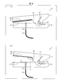
- FIG. 1 is a cross-sectional view showing a fingertip measuring unit 1 according to this embodiment.
- FIG. 2 is a diagram illustrating an example of the configuration of the fingertip measuring apparatus 100.
- FIG. 3 is a diagram illustrating the fingertip measurement unit 1 and the measurement member placement unit 110 included in the fingertip measurement device 100 of FIG. 4 is a diagram showing a measurement probe 113 provided in the fingertip measuring apparatus 100 of FIG.
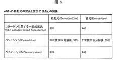
- FIG. 5 is a table showing the relationship between the wavelength of excitation light and the wavelength of fluorescence in AGEs.
- the fingertip measuring device 100 (measuring device) according to the present embodiment is configured to include a fingertip measuring unit 1, a measuring member placement unit 110, and a control device 120 as shown in FIG.
- the fingertip measurement unit 1 is a unit in which a user (subject) inserts his / her finger (fingertip portion A) in order to measure AGEs, as shown in FIG. As illustrated in FIG. 3A, the fingertip measurement unit 1 is disposed on the measurement member placement unit 110. As shown in FIG. 3A, the user can measure the AGEs present in the blood vessels in the fingertip portion A of the user by inserting the index finger into the fingertip measuring unit 1. The fingertip measuring unit 1 fixes the inserted user's finger. Details of the fingertip measurement unit 1 will be described later.
- the index finger is described as an example of the finger inserted into the fingertip measurement unit 1, but the finger inserted into the fingertip measurement unit 1 is not particularly limited, and may be, for example, the middle finger. .
- FIG. 1 and the cross-sectional view of the fingertip measuring unit described in another embodiment are cross-sectional views when the fingertip measuring unit is cut along the dotted line shown in FIG.
- the measurement member arrangement unit 110 arranges a member for measuring fluorescence derived from AGEs.
- the measurement member placement unit 110 includes a light source 111, a detector 112, and a measurement probe 113.
- the light source 111 is a light source that generates excitation light that irradiates the fingertip A. This excitation light is for detecting fluorescence derived from AGEs, and has a wavelength range suitable for detecting AGEs.
- a tube type such as a halogen or xenon light source, an LED (manufactured by Nichia Corporation, DOWA Electronics, etc.), LD, or the like can be used.
- the wavelength range of the excitation light generated by the light source 111 will be described in detail.
- CLF collagen-linked fluorescence
- Pentosidine and Vesperidin are representative examples of AGEs.
- Pentosidine has a structure in which pentose, equimolar lysine and arginine are cross-linked, and becomes a stable fluorescent substance after acid hydrolysis. This pentosidine has been reported to increase especially in the onset of diabetes and end-stage nephropathy.
- Vesperidin is isolated as a main fluorescent substance after acid hydrolysis of AGE-modified bovine serum albumin (BSA) and has a structure in which two molecules of lysine are cross-linked. Note that examples of AGEs not shown in FIG. 5 include glucosepane.
- the wavelength of the excitation light emitted from the light source 111 is most suitably 365 nm or a wavelength in the vicinity thereof.
- the excitation light varies depending on the type of AGEs, light from 315 nm to 400 nm in the UVA region to 400 nm to 600 nm in the visible light region can be used as the wavelength of the excitation light emitted from the light source 111. .
- the detector 112 receives fluorescence generated when the fingertip portion A is irradiated with excitation light, and measures the wavelength of the fluorescence and the fluorescence intensity for each wavelength. That is, the detector 112 measures how much fluorescence with which wavelength is detected.
- a CCD detector ILX511B; manufactured by SONY
- a photo detector SiPIN photodiode; manufactured by Hama Photonics
- a semiconductor detector such as a CMOS image sensor, a photomultiplier tube (PMT), a channeltron detector, etc. Is available.
- the detector 112 may be any detector that can detect light in the range of 350 nm to 500 nm. However, as can be seen from the table of FIG. 5, since there is a range of wavelengths to be detected depending on the type of AGEs, fluorescence can be used as the detector 112 as long as it can detect a range of 320 nm to 900 nm.
- the detector 112 may include a spectroscope.
- the fingertip measuring apparatus 100 can noninvasively measure the amount of AGEs present in the blood vessel.
- the measurement probe 113 is an excitation light irradiating unit that irradiates excitation light to a specific position on the skin surface of the fingertip A, and a fluorescence light receiving unit that receives fluorescence generated by irradiating the specific position with the excitation light. Function. That is, the measurement probe 113 is a combination of an excitation light irradiation unit and a fluorescence light receiving unit.
- the measurement probe 113 is an incident / outgoing coaxial optical fiber, and includes an incident fiber 114 that guides excitation light from the light source 111 to a specific position, and a fluorescence generated at the specific position as a detector.
- An output fiber 115 that guides light to 112 is provided.
- the end on the side where the incident fiber 114 and the outgoing fiber 115 are integrated is connected to the fingertip measurement unit 1.
- the incident fiber 114 and the outgoing fiber 115 are separated.
- the incident fiber 114 is connected to the light source 111, and the outgoing fiber 115 is connected to the detector 112.
- the incident fiber 114 and the outgoing fiber 115 may be provided as separate fibers instead of being coaxial.
- the control device 120 may be any device capable of adjusting brightness of the light source 111, switching control of irradiation or non-irradiation, storing data, displaying data, analyzing data, and the like, and is a personal computer, for example.
- the control device 120 displays a fluorescence spectrum based on the detection result (fluorescence intensity for each wavelength) input from the detector 112 on a monitor (not shown).
- the control device 120 may calculate an accumulation amount (fluorescence substance amount) of a fluorescent substance such as AGEs accumulated on the blood vessel wall of the fingertip A from the detection result input from the detector 112.
- the control device 120 provides easy-to-understand information for the user by converting the calculated amount of the fluorescent substance into an index (for example, five levels of health status) that indicates the user's health status and displaying it on a monitor (not shown). May be.
- FIG. 6 is a graph showing a temporal change in fluorescence intensity measured by the fingertip measuring apparatus 100 of FIG. 7 is a drawing for comparison with the fingertip measurement unit 1 of FIG. 1, (a) is a sectional view showing a part of the measurement device 10 for comparison, and (b) is shown in (a). It is a graph which shows the time-dependent change of the fluorescence intensity which the measuring apparatus 10 measures.
- the fingertip measurement unit 1 according to the present embodiment is configured to include a clamping unit 11, a placement unit 12, a fixing force supply unit 13, and a measurement unit 14 (an emitting unit and a light receiving unit). .
- the mounting part 12 is a member (pedestal part) that allows the measurement target part to be placed in contact with the mounting surface 17 (opposing surface).
- a finger including the fingertip A that is a measurement target part is placed on the placement surface 17 of the placement unit 12.
- a measuring unit 14 to be described later is connected to the mounting unit 12, and a measuring surface (measuring surface 143 shown in FIG. 9B) is formed at the end of the measuring unit 14.
- the measurement surface is an emission surface that emits excitation light, and a light-receiving surface that receives fluorescence emitted from the fingertip portion A. Further, the measurement surface is exposed at the same height as the placement surface 17. Thereby, as shown in FIG. 1B, when the fingertip A is placed on the placement portion 12, the measurement surface 143 of the measurement portion 14 comes into contact with the fingertip A.
- the clamping unit 11 is a unit (pressing plate) that faces the mounting unit 12 and clamps the measurement target site together with the mounting unit 12. Specifically, the user can insert the fingertip portion A between the placement portion 12 and the pinch portion 19 of the holding portion 11 by pressing the knob portion 18. After the user inserts the fingertip portion A, when the pressing on the knob portion 18 is stopped, the fingertip portion A is held between the placement portion 12 and the pinch portion 19. That is, when the finger is not inserted, the clamping unit 11 faces the mounting unit 12 so that the distal end portion of the clamping unit 11 and the distal end portion of the mounting unit 12 are in contact with or close to each other. These tip portions are end portions on the opposite side to the positions where they are connected to the fixing force supply unit 13, and are end portions into which fingers are inserted.
- the clamping unit 11 may include a buffer unit 15 and a positioning unit 16.
- the buffer unit 15 is provided on a surface (facing surface 20) facing the mounting surface 17 of the mounting unit 12.
- the facing surface 20 comes into contact with the inserted user's finger at the pinch portion 19.
- the facing surface 20 is a surface that transmits a force (for example, a restoring force) generated by the fixing force supply unit 13 described later to the finger as a force (load) applied to the measurement target region.
- a force for example, a restoring force
- the buffer portion 15 on the facing surface 20 that contacts the user's finger in the pinch portion 19, the load supplied to the fingertip A is equalized over the entire finger so that the user can press locally. The pain felt by can be reduced.
- rubber sponge, a biocompatible elastomer, etc. are mentioned.
- the positioning unit 16 positions the fingertip A, which is the measurement target site, on the placement surface 17 by defining the position of the tip of the inserted user's finger (fingertip A). is there. Specifically, the positioning unit 16 is a part of the surface of the pinch unit 19 that is touched by the tip of the inserted user's finger. In FIG. 1B, the buffer unit 15 is provided in the pinch unit 19. It is a surface that forms a substantially right angle with the surface (opposing surface 20). The user places the finger on the placement unit 12 so that the positioning unit 16 and the tip of the fingertip A are in contact with each other, so that the position of the fingertip A in contact with the measurement surface 143 of the measurement unit 14 is determined. It can always be almost the same position.
- the positioning part 16 of this embodiment is formed in the clamping part 11, it is not limited to this.
- the positioning unit 16 may be formed on the mounting unit 12.
- the positioning unit 16 according to the present embodiment determines the position only in the X-axis direction (finger insertion direction) when the XY plane is defined with respect to the placement surface 17, but is not limited thereto. is not. For example, not only the X-axis direction but also the position in the Y-axis direction (a direction substantially perpendicular to the finger insertion direction on the placement surface 17) may be determined.
- the mounting surface 17 is sandwiched at a position separated from the measurement surface 143 (see FIG. 9B) by a predetermined distance in the Y-axis direction.
- the convex part extended in the part 11 direction may be formed.
- the predetermined distance may be, for example, a distance that allows the vicinity of the center of the fingertip A of a normal adult finger to be placed on the measurement surface 143.
- the fixing force supply unit 13 supplies a force capable of fixing the relative positional relationship between the measurement target region and the measurement unit 14 to the measurement target region via the clamping unit 11.
- the fixing force supply unit 13 in the present embodiment is a spring-type hinge.
- the clamping part 11 is connected so that it can rotate with respect to the mounting part 12 about the connection part 131 which the clamping part 11 has as a rotating shaft.
- the fixing force supply unit 13 is provided in the vicinity of the coupling unit 131 so that the clamping unit 11 rotates in a direction approaching the placement unit 12 with the coupling unit 131 as a rotation axis. That is, in this embodiment, the fingertip measurement unit 1 has a so-called clip structure.
- the fingertip measurement unit 1 when the user presses the knob portion 18 of the clamping unit 11, a restoring force that tries to return to the state of FIG.
- FIG. 1B when a finger is inserted between the pinch part 19 and the mounting part 12 of the holding part 11 and the pressing to the knob part 18 is stopped, the restoring force is applied to the holding part. 11 to be told. And the restoring force transmitted to the clamping part 11 is supplied to the fingertip part A as a load. Thereby, the relative positional relationship between the fingertip A and the measurement unit 14 is fixed. In other words, the fingertip portion A is fixed while being pressed against the measurement surface 143 and the placement surface 17 of the measurement unit 14.
- the load supplied to the fingertip A is small, the relative positional relationship between the blood vessel position of the fingertip A and the measurement unit 14 may change during measurement due to the elasticity of the fingertip A. There is sex. For this reason, the load supplied to the fingertip part A needs to be a load to the extent that the relative positional relationship between the fingertip part A and the measurement unit 14 is fixed. Since the relative positional relationship between the fingertip A and the measurement unit 14 is fixed, the distance between the blood vessel position in the fingertip A and the measurement unit 14 (measurement surface 143 of the measurement unit 14) is fixed. The detection result (the detected fluorescence intensity) is stable.
- the load supplied to the fingertip is about 3N, and It was found that the fluorescence intensity was not stable at a load of 3N. That is, in the case of the fingertip measurement unit 1, it is preferable that the load supplied to the fingertip portion A is larger than 3N. Further, the inventor of the present application has found that the fluorescence intensity is stable if the load supplied to the fingertip portion A is 6N as shown in FIG. That is, in the case of the structure of the fingertip measurement unit 1, the load transmitted to the fingertip A is more preferably 6N or more, and the fixing force supply unit 13 can supply a load of 6N or more to the fingertip A. It is preferable that a strong force (restoring force) can be generated. If the load supplied to the fingertip A is too large, the fingertip A may be painful, so the upper limit of the load is preferably about 9N.
- FIG. 7A in the case of the measurement apparatus 10 that does not include the fixing force supply unit 13 and that measures the fluorescence intensity by placing the fingertip A on the placement unit 72, FIG. As shown in (b), the measured fluorescence intensity decreases with the passage of time. This is because the load is not supplied from the clamping unit 11 to the fingertip A due to the restoring force from the fixing force supply unit 13 (the relative positional relationship is not fixed). This is because the distance between the measurement unit 74 and the blood vessel position of the fingertip A increases because the shape of the apex A changes. Note that the placement unit 72, the measurement unit 74, and the measurement probe 713 illustrated in FIG. 7A are the same as the placement unit 12, the measurement unit 14, and the measurement probe 113 of the fingertip measurement unit 1, respectively. Detailed description will be omitted here.
- the measurement unit 14 is an end (measurement attachment) on the side where the incident fiber 114 and the emission fiber 115 of the measurement probe 113 are integrated.
- the measurement unit 14 has an integrated function of an emitting unit that emits excitation light and a light receiving unit that receives fluorescence.
- the measurement surface 143 of the measurement unit 14 is exposed at the same height as the placement surface 17 (is present in a plane including the placement surface 17), and the placement unit 12 is touched by the finger. When the apex A is placed, the measurement surface 143 comes into contact with the finger apex A.
- excitation light is emitted from the measurement surface 143 of the measurement unit 14 toward the fingertip A, and fluorescence emitted from the fingertip A upon receiving the excitation light is received by the measurement surface 143. Therefore, the measuring unit 14 can irradiate the fingertip A that is in contact with the excitation light, and can receive the fluorescence from the fluorescent substances (AGEs) in the blood vessels in the fingertip A.
- AGEs fluorescent substances
- the fluorescence intensity from the fluorescent substances (AGEs) in the blood vessel in the fingertip A depends on the distance between the blood vessel position and the measurement unit 14. For this reason, if the fingertip portion A is not sufficiently fixed, the distance between the blood vessel position and the measurement portion 14 is slightly changed due to the elasticity of the fingertip portion A and the like, and the fluorescence intensity is not stable.
- a load is applied to the fingertip portion A via the clamping portion 11 by the restoring force of the fixing force supply portion 13 (spring-type hinge). Thereby, since it can suppress that the distance of the blood vessel position of the fingertip part A and the measurement part 14 changes with progress of time, the fluorescence intensity measured can be stabilized.
- FIG. 8 is a cross-sectional view showing the fingertip measuring unit 2 according to the present embodiment.
- the fingertip measurement unit 2 has a configuration in which the measurement unit 14 protrudes from the placement surface 17 of the placement unit 12. That is, the measurement surface 143 of the measurement unit 14 is configured to be closer to the placement finger 17 with respect to the fingertip portion A to be placed.
- the fingertip A is placed on the placement portion 12, and the load is applied to the fingertip A via the clamping portion 11 by the restoring force of the fixing force supply portion 13. When applied, the fingertip A is strongly pressed against the protruding portion (measurement surface 143) of the measurement unit 14.
- the fingertip portion A is pressed against the measurement surface 143 having a smaller area than the placement surface 17, and thus when the load supplied to the fingertip portion A is constant, the fingertip measurement according to the first embodiment is performed.
- the load per unit area (load pressure) supplied to the fingertip A is increased.
- the force (restoring force) supplied from the fixing force supply unit 13 is compared with that of the fingertip measurement unit 1 in order to obtain a load capable of fixing the relative positional relationship between the fingertip A and the measurement unit 14. Can be made smaller. Therefore, even if the restoring force supplied by the fixing force supply unit 13 is further reduced, the measured fluorescence intensity can be stabilized.
- the length of the protruding portion of the measurement unit 14 is preferably 0.5 mm or more and 2 mm or less, and more preferably about 1 mm.
- the measurement unit 14 comes into contact with the measurement surface 143 in the fingertip A. The part is pushed up. Thereby, since the position shift of the fingertip part A can be suppressed as compared with the fingertip measurement unit 1, the value of the load supplied to the fingertip part A stabilizes the fluorescence intensity in the fingertip measurement unit 1. It may be smaller than a load value (predetermined value, for example, 6N) necessary for the purpose. The same applies to the fingertip measurement unit from which the measurement unit 14 protrudes among the fingertip measurement units described later.
- FIG. 9A is a cross-sectional view showing the fingertip measuring unit 3 according to the present embodiment
- FIG. 9B is a schematic view showing the placement portion 12 as viewed from the holding portion 11 direction.
- the fingertip measurement unit 3 has an outer edge portion 34 (sleeve) formed around the measurement portion 14 protruding from the placement surface 17 of the placement portion 12. It is the structure which is done.
- the measurement attachment is realized by the measurement unit 14 and the outer edge 34.
- the outer edge 34 according to the present embodiment is a relaxation member that relaxes the force supplied from the measurement unit 14 to the fingertip A when a load capable of fixing the relative positional relationship is supplied to the fingertip A. is there.
- the outer edge portion 34 has a protruding portion having the same length as the measurement portion 14 (length from the placement surface 17 to the measurement surface 143 of the measurement portion 14).
- the measurement surface 143 exists in a plane including the outer edge contact surface 341.
- the outer edge portion 34 according to the present embodiment has a cylindrical shape, and the measurement unit 14 is arranged in a space portion inside the cylinder.
- the region formed by the outer periphery of the measurement unit 14 and the outer periphery of the outer edge 34 is an outer edge contact surface 341 that comes into contact with the user's finger (finger tip A). ing. That is, the outer edge contact surface 341 is a surface in the outer edge portion 34 that can contact the fingertip portion A and faces the sandwiching portion 11.
- the fingertip portion A is pressed against the outer edge contact surface 341 having a larger area than the measurement surface 143, and therefore, compared to the fingertip measurement unit 2 according to the second embodiment, Distributing the supplied force can reduce the pain that the user feels due to local pressing. Further, there is an advantage that the measurement mark generated in the fingertip A when the fingertip A is strongly pressed against the measurement unit 14 does not remain in the fingertip measurement unit 3 according to the present embodiment.
- the fingertip measurement according to the first embodiment is performed when the load supplied to the fingertip A is constant. Compared with the unit 1, the load pressure supplied to the fingertip A is increased. In other words, the force (restoring force) supplied from the fixing force supply unit 13 is compared with that of the fingertip measurement unit 1 in order to obtain a load capable of fixing the relative positional relationship between the fingertip A and the measurement unit 14. Can be made smaller. Therefore, even if the restoring force supplied by the fixing force supply unit 13 is further reduced, the measured fluorescence intensity can be stabilized.
- the outer diameter of the outer edge 34 is preferably 1 cm or less, and more preferably about 8 mm.
- the lengths of the protruding portions of the measurement unit 14 and the outer edge 34 are preferably 0.5 mm or more and 2 mm or less, more preferably about 1 mm. preferable.
- the outer edge part 34 which concerns on this embodiment is a cylindrical shape, the shape of the outer edge part 34 is not limited to this, For example, the square cylinder shape by which the measurement part 14 was arrange
- the outer edge 34 becomes the outer edge contact surface 341 in the fingertip A. It will be in the state which pushes up the part which contacts. Thereby, since the position shift of the fingertip part A can be suppressed as compared with the fingertip measurement unit 1, the value of the load supplied to the fingertip part A stabilizes the fluorescence intensity in the fingertip measurement unit 1. It may be smaller than a load value (predetermined value, for example, 6N) necessary for the purpose. The same applies to a fingertip measuring unit including the outer edge portion 34 among fingertip measuring units described later.
- examples of the material of the outer edge portion 34 include acrylic resin and stainless steel (SUS). However, the material is not limited to this, and it is sufficient that the force supplied from the measurement unit 14 to the fingertip A can be reduced.
- FIG. 10 is a cross-sectional view showing the fingertip measurement unit 4 according to this embodiment.
- the fingertip measurement unit 4 includes a light receiving surface (measurement surface 143) that is a surface that receives fluorescence from the fingertip portion A in the measurement unit 14 having an outer edge portion 34 around it. ) Is located at a position deeper than the outer edge contact surface 341, the recess 35 is formed by the outer edge part 34 and the measurement part 14.
- the measurement surface 143 of the measurement unit 14 that is at the same height as the outer edge contact surface 341 is the fingertip according to the present embodiment.
- the measurement unit 4 has the same height as the placement surface 17. That is, the measurement surface 143 exists in a plane including the placement surface 17.
- the fingertip measurement unit 4 forms the recess 35 by the inner side surface of the outer edge portion 34 and the measurement surface 143 of the measurement unit 14. Therefore, when the outer edge contact surface 341 is pressed against the fingertip A, the measurement surface 143 of the measurement unit 14 is not in contact with the fingertip A, so that the measurement surface 143 can always be maintained in a clean state. .
- the measurement surface 143 does not have to exist in the plane including the placement surface 17, and the recess 35 is formed so as to be out of contact with the fingertip A when the finger is inserted. It is sufficient that the position is defined. However, if the outer edge contact surface 341 and the measurement surface 143 are too far apart, the intensity of received fluorescence is weakened. Therefore, the distance between the outer edge contact surface 341 and the measurement surface 143, that is, the height of the recess 35 is 0.5 mm or more and 2 mm. The following is preferable, and about 1 mm is more preferable.
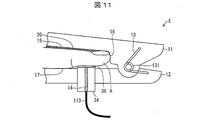
- FIG. 11 is a cross-sectional view showing the fingertip measurement unit 5 according to this embodiment.
- the fingertip measurement unit 5 according to the present embodiment is similar to the fingertip measurement unit 3 according to the third embodiment, with the measurement unit 14 protruding from the placement surface 17 of the placement unit 12.
- the outer edge 34 is formed around the periphery.
- a translucent member 36 that can be attached to and detached from the outer edge contact surface 341 is provided.
- the translucent member 36 according to the present embodiment has a cylindrical shape having the same bottom area as the surface area including the outer edge contact surface 341 and the measurement surface 143 of the measurement unit 14.
- the translucent member 36 has a bottom surface in contact with the outer edge contact surface 341 made of quartz, and other parts made of plastic.
- quartz Since quartz is excellent in translucency, even if the translucent member 36 is disposed on the measurement surface 143, the intensity of the excitation light reaching the fingertip A from the measurement surface 143, and the fingertip A Thus, the intensity of fluorescence reaching the measurement surface 143 of the measurement unit 14 can be maintained.
- the fingertip measuring unit 5 is provided with the translucent member 36 that can be attached to and detached from the outer edge contact surface 341.
- the measurement surface 143 of the measurement unit 14 is not in contact with the fingertip part A. Therefore, the measurement surface 143 can always be maintained in a clean state.
- the translucent member 36 is detachable, the translucent member 36 can be changed every time the user using the fingertip measurement unit 5 is changed, so that hygiene can be improved. Can do.
- the translucent member 36 has a cylindrical shape with the same bottom area as the surface area including the outer edge contact surface 341 and the measurement surface 143 of the measurement unit 14, but is limited to this configuration. is not.
- the bottom area of the translucent member 36 is not limited as long as the measurement surface 143 and the outer edge contact surface 341 of the measurement unit 14 and the fingertip A can be brought into contact with each other.
- the outer edge contact surface 341 and the measurement surface 143 of the measurement unit 14 are not required.
- the area may not be the same.
- the translucent member 36 may be other than a cylindrical shape such as a quadrangular prism shape, but in order to stably match the outer edge contact surface 341, the shape of the bottom surface of the translucent member 36 is measured. 143 and the shape of the surface including the outer edge contact surface 341 are preferable.
- the height of the translucent member 36 (the distance from the surface in contact with the fingertip part A to the surface in contact with the outer edge contact surface 341 in the translucent member 36) is used to maintain the intensity of received fluorescence. Moreover, 0.5 mm or more and 2 mm or less are preferable, and about 1 mm is more preferable.
- the translucent member 36 may have a mirror surface portion (not shown) capable of reflecting fluorescence on its side surface. Thereby, the fluorescence emitted from the fingertip portion A is reflected by the mirror surface portion. Therefore, the fluorescence emitted from the fingertip A can be efficiently collected on the measurement surface 143 of the measurement unit 14.
- the translucent member 36 may be disposed on the outer edge contact surface 341 in the fingertip measurement unit 4 according to the fourth embodiment.
- the total height of the translucent member 36 and the recess 35 (that is, The distance from the surface of the translucent member 36 that can contact the fingertip A to the measurement surface 143 of the measurement unit 14 is preferably 0.5 mm or more and 2 mm or less.
- FIG. 12 is a cross-sectional view showing the fingertip measurement unit 6 according to the present embodiment and a fingertip measurement unit 61 that is a modification of the fingertip measurement unit 6.
- the fingertip measurement unit 6 is a surface that receives fluorescence from the fingertip portion A, like the fingertip measurement unit 4 according to the fourth embodiment. Since the measurement surface 143 is located at a position deeper than the outer edge contact surface 341, the outer edge portion 34 and the measurement portion 14 form a recess 35. The difference from the fingertip measurement unit 4 is that a mirror surface portion 37 that reflects incident fluorescence is provided on the side surface in the recess 35.
- the mirror surface portion 37 according to the present embodiment is formed by evaporating aluminum on the side surface in the recess 35.
- the fingertip A and the measurement surface 143 of the measurement unit 14 are separated from each other. Therefore, the fluorescence emitted from the fingertip A is absorbed by the side surface in the recess 35, thereby measuring the measurement surface. The intensity of fluorescence reaching 143 may be weakened.
- the fingertip measurement unit 6 according to the present embodiment includes the mirror surface portion 37 on the side surface in the recess 35, the fluorescence is absorbed by the side surface in the recess 35 by the reflection of the fluorescence by the mirror surface portion 37. Not.
- the fluorescence can be incident on the measurement surface 143 in a state in which the intensity of the fluorescence emitted from the fingertip portion A is suppressed from being weakened, so that the fluorescence can be efficiently collected. That is, a decrease in fluorescence intensity due to the formation of the recess 35 can be suppressed, and the measured fluorescence intensity can be maintained.
- the fingertip measurement unit 61 may be a fingertip measurement unit 61 having a mirror surface portion 37 on the side surface in the tapered recess 38 as shown in FIG. Since the concave portion is a tapered concave portion 38 (the sectional shape of the concave portion is opened in a fan shape), the fluorescence can be more efficiently condensed on the measurement surface 143 of the measurement unit 14, and thus the fingertip measurement unit 6 The fluorescence intensity can be increased compared to.
- the mirror surface part 37 which concerns on this embodiment is formed by vapor-depositing aluminum on the side surface in the recessed part 35 and the recessed part 38, the mirror surface part 37 should just be what can reflect fluorescence, It is not limited to aluminum.
- the translucent member 36 described in the fifth embodiment may be arranged on the outer edge contact surface 341 of the outer edge portion 34 included in the fingertip measuring units 6 and 61 according to the present embodiment.
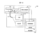
- FIG. 13 is a diagram illustrating a configuration of a fingertip measuring apparatus 200 according to the present embodiment.
- the fingertip measuring device 200 is configured to include a fingertip measuring unit 7, a measuring member placement unit 110, and a control device 220.
- positioning part 110 is the same as the measurement member arrangement
- the fingertip measuring unit 7 further includes a load sensor 222 (fixed force sensor) that measures the value of the load applied to the fingertip portion A of the inserted finger.
- the fingertip measuring unit 7 replaces the fixing force supply unit 13 included in the fingertip measuring units 1 to 6 with a load so that the load becomes a predetermined value or more according to the measurement result by the load sensor 222.
- This is a configuration including a fixed force supply unit 30 controlled by the control unit 223.
- the load sensor 222 is a sensor that measures the value of the load applied to the fingertip A of the inserted finger through the clamping unit 11 by the fixing force supply unit 30. Specifically, the load sensor 222 measures the load applied to the fingertip A via the clamping unit 11 by the fixing force supply unit 30 and outputs the measurement result to the load control unit 223. For example, the load sensor 222 receives an instruction (measurement start instruction) for measuring the value of the load supplied from the clamping unit 11 to the fingertip A from the load control unit 223 and starts measuring the load. The load sensor 222 continuously measures the change over time of the load applied to the fingertip A by the fixing force supply unit 30 via the holding unit 11 and outputs the measurement result to the load control unit 223 continuously. Details of the load control unit 223 will be described later.
- the load sensor 222 has, for example, a sheet shape, and is attached to a location (for example, the buffer portion 15, the placement surface 17, the outer edge contact surface 341, etc.) that the fingertip portion A of the fingertip measurement unit 7 touches.
- a location for example, the buffer portion 15, the placement surface 17, the outer edge contact surface 341, etc.
- the load sensor 222 is disposed in the vicinity of the measurement unit 14 on the placement surface 17.
- the shape and location of the load sensor 222 are not limited.
- the fixing force supply unit 30 is a driving device that supplies a rotational force to the clamping unit 11 such that the clamping unit 11 rotates in a direction approaching the mounting unit 12 with the connecting unit 131 as a rotation axis. It is. Specifically, when a fixing instruction for applying a predetermined load (for example, 6N) to the fingertip A is supplied from the load control unit 223, the fixing force supply unit 30 displays the load indicated by the fixing instruction. Is applied to the inserted fingertip A via the pinching portion 11. For example, when the fixing force supply unit 30 is driven, a force in the direction of the placement unit 12 is supplied to the clamping unit 11.
- a predetermined load for example, 6N
- the clamping part 11 moves toward the mounting part 12, and the fingertip A inserted into the fingertip measurement unit 7 is clamped so as to be pressed against the mounting part 12 by the clamping part 11, and the fingers that are sandwiched A predetermined load is applied to the apex A.
- the fixing force supply unit 30 is shown outside the sandwiching unit 11 and the mounting unit 12 in consideration of the legibility of the drawing. It is provided in the vicinity of 131.
- the fingertip measuring unit 7 has a configuration capable of detecting that a user's finger has been inserted. Then, when the user's finger is inserted, insertion information indicating that the finger has been inserted is output to the load control unit 223.
- the other configuration of the fingertip measurement unit 7 is the same as that of any of the fingertip measurement units 1 to 6 described in the first to sixth embodiments, and thus description thereof is omitted here.
- Control device 220 The control device 220 of the fingertip measuring apparatus 200 according to this embodiment includes a control unit 221. Since other configurations are the same as those of the control device 120 described in the first embodiment, description thereof is omitted here.
- the control unit 221 controls each part of the fingertip measuring apparatus 200.
- the controller 221 includes a load controller 223 (fixed force controller).
- the load control unit 223 controls the fixing force supply unit 30 so that the load applied to the fingertip A of the inserted finger becomes a predetermined value according to the measurement result by the load sensor 222. Specifically, when the insertion information is supplied from the fingertip measurement unit 7, the load control unit 223 starts controlling the fixing force supply unit 30. More specifically, when the insertion information is supplied, the load control unit 223 issues a fixing instruction for giving a predetermined load (for example, 6N) to the fingertip A to the fixing force supply unit 30. Output. By this fixing instruction, the fixing force supply unit 30 of the fingertip measurement unit 7 supplies a force in the direction of the placement unit 12 to the clamping unit 11 of the fingertip measurement unit 7, for example.
- a predetermined load for example, 6N
- the clamping part 11 moves toward the mounting part 12, and the fingertip A inserted into the fingertip measurement unit 7 is clamped so as to be pressed against the mounting part 12 by the clamping part 11, and the fingers that are sandwiched A predetermined load is applied to the apex A.
- the load control unit 223 outputs the measurement start instruction to the load sensor 222.
- the fixing force supply unit 30 is controlled so that the load supplied to the fingertip A is equal to or greater than the predetermined value.
- the load control unit 223 gives an instruction to increase the force supplied to the clamping unit to the fixed force supply unit 30, and the load supplied to the fingertip A via the clamping unit 11 becomes a predetermined value or more.
- the fingertip measuring apparatus 200 measures the value of the load applied to the fingertip A of the inserted finger by the fixing force supply unit 30 via the clamping unit 11.
- a load control unit 223 that controls the load applied to the fingertip A by the fixing force supply unit 30 via the sandwiching unit 11 according to a measurement result by the load sensor 222 to be a predetermined value or more, It is the structure provided with.
- the fluorescence intensity can be stabilized simply by setting the predetermined value in advance as a value (for example, 6N) that does not change with time.
- FIG. 14 is a cross-sectional view showing a modification of the fingertip measurement unit. Although FIG. 14 is described as a modification of the second embodiment, this modification can be applied to the first to sixth embodiments of the present invention.
- the fingertip measurement units 1 to 6 described in the first to sixth embodiments have a fixing force supply unit 13 that is a spring-type hinge.
- the fixing force supply unit is not limited as long as it can supply a load capable of fixing the relative positional relationship between the fingertip A and the measurement unit 14 to the fingertip A via the clamping unit 11. It is not limited to.
- the fingertip measurement unit includes a fingertip measurement unit 31 that includes a fixing force supply unit 31 that is a spring that connects the pinch unit 19 of the holding unit 11 and the mounting unit 12. 21 may be sufficient.
- the fixing force supply unit 31 is extended by inserting a finger into the fingertip measuring unit 21, and at the same time, a restoring force is generated to return to the original state. This restoring force is transmitted as a load from the pinch part 19 to the fingertip part A, so that the relative positional relationship between the fingertip part A and the measurement part 14 is fixed.
- the fingertip measurement unit 21 and the fixing force supply unit 31 are displayed in a superimposed manner for the sake of simplification of the drawing, but in actuality, in FIG.
- a supply unit 31 is arranged. That is, the two fixing force supply units 31 are substantially perpendicular to the insertion direction of the fingers on the mounting surface 17 so that the fingers can be inserted into the mounting unit 12. (Direction). Note that the strength, the number, and the arrangement position of the fixing force supply unit 31 may be determined so that the relative positional relationship between the fingertip A and the measurement unit 14 is fixed.
- the fingertip measurement unit is a fingertip measurement unit 22 including a fixing force supply unit 32 in which a part of the sandwiching portion 11 is a load member made of a metal material having a high specific gravity.
- the fixing force supply unit 32 is a metal having a high specific gravity
- the pressing force that presses the fingertip A by the weight of the fixing force supply unit 32 can be supplied to the clamping unit 11.
- the fixing force supply part 32 (load member) iron or stainless steel (SUS) etc.
- the fixing force supply unit 32 may be provided independently on the clamping unit 11.
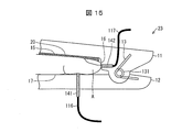
- FIG. 15 is a cross-sectional view illustrating a modification of the fingertip measurement unit.
- FIG. 15 is described as a modification of the second embodiment, but this modification can be applied to the first to seventh embodiments and the first modification of the present invention.
- the measurement unit 14 has an integrated function of an emission unit that emits excitation light and a light reception unit that receives fluorescence.
- the measurement unit is not limited to this configuration.
- the output fiber 116 and the incident fiber 117 may be used as the measurement probe.
- the outgoing fiber 116 and the incident fiber 117 have the same functions as the outgoing fiber 115 and the incoming fiber 114, respectively, and thus description thereof is omitted here.
- the measurement unit of the fingertip measurement unit 23 is the end of the emission fiber 116 and receives the fluorescence, and the end of the incident fiber 117 and the excitation light. And an emission part 142 that emits light. That is, the measurement unit according to this modification has a configuration in which the light receiving unit 141 and the emitting unit 142 are separated.
- the light receiving unit 141 according to this modification is disposed on the mounting unit 12 in the same manner as the measurement unit 14 of the first to seventh embodiments.
- the emission part 142 according to this modification is disposed in the positioning part 16 of the clamping part 11. Not only this but the emission part 142 should just be arrange
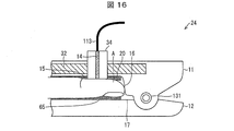
- FIG. 16 is a cross-sectional view illustrating a modification of the fingertip measurement unit.
- FIG. 16 is described as a modification of the third embodiment, but this modification can be applied to the first to seventh embodiments and the first modification of the present invention.
- the fingertip measurement unit described in the first to seventh embodiments has a configuration in which the measurement unit 14 is disposed on the placement unit 12.
- the member on which the measurement unit 14 is disposed is not limited to the placement unit 12.
- the measurement unit 14 may be disposed in the clamping unit 11.
- the mounting surface 17 may be provided with a buffer unit 65.
- the fingertip measurement unit 24 shown in FIG. 16 has a configuration including the fixing force supply unit 32 that is a load member made of a metal material having a high specific gravity, but is not limited to this configuration.
- the fixing force supply unit of the present modification may be the fixing force supply unit 13 that is a spring-type hinge, or the fixing force supply unit 31 that is a spring. May be.
- the outer edge portion 34 may be made of a metal material having a heavy specific gravity, and may be used in place of the fixing force supply portion 32.
- the fingertip measurement unit 24 shown in FIG. 16 was the structure provided with the buffer part 15 in the opposing surface 20
- the fingertip measurement unit which concerns on this modification is not limited to the structure shown in FIG.
- the buffer unit 15 may not be provided, and the measurement unit 14 and the outer edge 34 may protrude from the facing surface 20, or the buffer unit 15 and the outer edge 34 may not be provided, and the measurement unit 14 may be provided from the facing surface 20.
- the structure which protrudes may be sufficient.
- the present invention can be used for a measuring apparatus that measures the amount of the fluorescent substance based on the intensity of fluorescence generated from the fluorescent substance in the living body, and is particularly suitable for a measuring apparatus that monitors AGEs in the living body. .
- Fingertip Measurement Unit 2 Fingertip Measurement Unit 3 Fingertip Measurement Unit 4 Fingertip Measurement Unit 5 Fingertip Measurement Unit 6 Fingertip Measurement Unit 7 Fingertip Measurement Unit 21 Fingertip Measurement Unit 22 Fingertip Measurement Unit 23 Fingertip Measurement Unit 24 fingertip measurement unit 61 fingertip measurement unit 11 clamping unit 12 placement unit 13 fixing force supply unit 14 measurement unit (light emitting unit, light receiving unit) 17 Mounting surface (opposite surface) DESCRIPTION OF SYMBOLS 20 Opposing surface 30 Fixing force supply part 31 Fixing force supply part 32 Fixing force supply part 34 Outer edge part 35 Concave part 36 Translucent member 37 Mirror surface part 38 Concave part 100 Fingertip measuring apparatus (measuring apparatus) 141 Light-receiving part 142 Light-emitting part 143 Measurement surface (light-receiving surface) 200 Fingertip measuring device (measuring device) 222 Load sensor (fixed force sensor) 223 Load control unit (fixed force control unit) 341 outer edge contact surface A fingertip (measurement target part
Landscapes
- Life Sciences & Earth Sciences (AREA)
- Health & Medical Sciences (AREA)
- Physics & Mathematics (AREA)
- Heart & Thoracic Surgery (AREA)
- Molecular Biology (AREA)
- Pathology (AREA)
- Engineering & Computer Science (AREA)
- Biomedical Technology (AREA)
- Veterinary Medicine (AREA)
- Medical Informatics (AREA)
- Biophysics (AREA)
- Surgery (AREA)
- Animal Behavior & Ethology (AREA)
- General Health & Medical Sciences (AREA)
- Public Health (AREA)
- Optics & Photonics (AREA)
- Spectroscopy & Molecular Physics (AREA)
- Investigating, Analyzing Materials By Fluorescence Or Luminescence (AREA)
- Measurement Of The Respiration, Hearing Ability, Form, And Blood Characteristics Of Living Organisms (AREA)
Abstract
Description
以下、本発明の実施の形態について、詳細に説明する。以下で説明する実施形態では、特定の波長の光(励起光)により励起して蛍光を発する蛍光物質としてAGEs(Advanced Glycation Endproducts:後期糖化反応生成物)の量を測定する測定装置に本発明を適用した例について説明する。また、以下で説明する実施形態では、指先(以下、指尖部と呼称する)に励起光を照射し、指尖部に存在する蛍光物質から生じる蛍光の強度に基づいて、上記蛍光物質の量を測定する指尖測定装置に本発明を適用した例を説明する。なお、適用例は上記指尖測定装置に限定されず、生体における測定対象部位に対して照射した励起光によって励起された上記生体内の蛍光物質から生じる蛍光の強度に基づいて、上記蛍光物質の量を測定する測定装置であれば、本発明を適用可能である。この場合、上記測定対象部位としては、腕、手首、手のひら、および耳朶などが挙げられる。
本発明の一実施形態において、図1から図6に基づいて説明すれば以下のとおりである。
まず、図1~図5を参照して、本発明に係る指尖測定装置100の構成について説明する。図1は、本実施形態に係る指尖測定ユニット1を示す断面図である。また図2は、指尖測定装置100の構成の一例を示す図である。また図3は、図2の指尖測定装置100が備える指尖測定ユニット1および測定部材配置部110を示す図である。また図4は、図2の指尖測定装置100が備える測定プローブ113を示す図である。また図5は、AGEsにおける、励起光の波長と蛍光の波長との関係を表す表である。
測定部材配置部110は、AGEsに由来する蛍光を測定するための部材を配置するものである。測定部材配置部110は、光源111、検出器112、および測定プローブ113を備える構成である。
光源111は、指尖部Aに照射する励起光を生成する光源である。この励起光は、AGEs由来の蛍光を検出するためのものであり、AGEsを検出するために適した波長範囲を有している。光源111として用いられる光源の種類としては、ハロゲンやキセノン光源のような管球タイプのものや、LED(日亜化学工業株式会社製、DOWAエレクトロニクス社製など)、LD等が利用可能である。
検出器112は、指尖部Aに励起光が照射されることによって発生した蛍光を受光し、その蛍光の波長および波長ごとの蛍光強度を測定するものである。すなわち、検出器112は、どの波長の蛍光がどの程度の強さで検出されたのかを測定する。検出器112としては、CCD検出器(ILX511B;SONY社製)や、フォトディテクタ(SiPIN フォトダイオード;浜ホトニクス社製)、CMOSイメージセンサといった半導体検出器、光電子倍増管(PMT)やチャンネルトロン検出器などが利用可能である。
測定プローブ113は、指尖部Aの皮膚表面における特定位置に対して励起光を照射する励起光照射部と、励起光が当該特定位置に照射されることによって生じる蛍光を受光する蛍光受光部として機能する。すなわち、測定プローブ113は、励起光照射部と蛍光受光部との組み合わせである。
制御装置120は、光源111の輝度調整、照射または非照射の切替制御、データの記憶、データの表示およびデータの分析などが可能な装置であればよく、例えばパーソナルコンピュータである。また、制御装置120は、検出器112から入力された検出結果(波長ごとの蛍光強度)に基づく蛍光スペクトルを、図示しないモニターに表示する。さらに、制御装置120は、検出器112から入力された検出結果から、指尖部Aの血管壁に蓄積するAGEsなどの蛍光物質の蓄積量(蛍光物質量)を算出してもよい。制御装置120は、算出した蛍光物質量をユーザの健康状態が分かる指標(例えば、5段階の健康状態レベルなど)に変換して、図示しないモニターに表示することで、ユーザにとって分かりやすい情報を提供してもよい。
次に、図1、図6、および図7を参照して、本実施形態に係る指尖測定ユニット1の詳細について説明する。図6は、図2の指尖測定装置100が測定する蛍光強度の経時変化を示すグラフである。また図7は、図1の指尖測定ユニット1との比較用図面であり、(a)は比較用の測定装置10の一部を示す断面図であり、(b)は(a)に示す測定装置10が測定する蛍光強度の経時変化を示すグラフである。図1に示すように、本実施形態に係る指尖測定ユニット1は、挟持部11、載置部12、固定力供給部13、および測定部14(出射部、受光部)を備える構成である。
載置部12は、測定対象部位を載置面17(対向面)に接触するように載置可能とする部材(台座部)である。図1の(b)に示すように、本実施形態では、測定対象部位である指尖部Aを含む指が載置部12の載置面17に載置される。また、載置部12には後述する測定部14が接続されており、測定部14の端部に測定面(図9の(b)に示す測定面143)が形成されている。測定面は、励起光を出射する出射面であり、かつ、指尖部Aから発せられた蛍光を受光する受光面である。また、測定面は、載置面17と同じ高さで露出している。これにより、図1の(b)に示すように、載置部12に指尖部Aが載置されると、測定部14の測定面143が指尖部Aに接触することとなる。
挟持部11は、載置部12と対向し、載置部12とともに測定対象部位を挟持するもの(押圧版)である。具体的には、ユーザはつまみ部18を押下することによって、載置部12と挟持部11のピンチ部19との間に指尖部Aを挿入することが可能となる。ユーザが指尖部Aを挿入した後、つまみ部18への押下を止めると、載置部12とピンチ部19によって指尖部Aが挟持される。すなわち、指が挿入されていない状態においては、挟持部11は、挟持部11の先端部と載置部12の先端部とが接触または近接するように、載置部12と対向している。これらの先端部は、固定力供給部13と接続された位置とは反対側の端部であり、指が挿入される端部である。
固定力供給部13は、測定対象部位と測定部14との相対位置関係を固定可能な力を、挟持部11を介して測定対象部位に供給するものである。本実施形態における固定力供給部13は、ばね型の蝶番である。挟持部11は、挟持部11が有する連結部131を回転軸として載置部12に対して回転できるように連結されている。固定力供給部13は、挟持部11が連結部131を回転軸として載置部12に近づく方向に回転するように、連結部131の近傍に設けられている。すなわち、本実施形態では、指尖測定ユニット1は、いわゆるクリップ構造となっている。指尖測定ユニット1では、ユーザが挟持部11のつまみ部18を押下することにより、固定力供給部13には図1の(a)の状態に戻ろうとする復元力が働く。ここで、図1の(b)に示すように挟持部11のピンチ部19と載置部12との間に指を挿入し、つまみ部18への押下を止めると、上記復元力が挟持部11に伝えられる。そして、挟持部11に伝えられた復元力は荷重として指尖部Aに供給される。これにより、指尖部Aと測定部14との相対位置関係が固定される。換言すれば、指尖部Aは測定部14の測定面143と載置面17とに押し付けられた状態で固定される。
測定部14は、上述した測定プローブ113の入射用ファイバー114と出射用ファイバー115とが一体となっている側の端部(測定アタッチメント)である。つまり、測定部14は、励起光を出射する出射部および蛍光を受光する受光部の機能が一体となっている。また、上述したように、測定部14の測定面143は載置面17と同じ高さで露出しており(載置面17を含む平面内に存在しており)、載置部12に指尖部Aが載置されると、測定面143が指尖部Aに接触する。これにより、測定部14の上記測定面143から指尖部Aに向けて励起光が出射され、当該励起光を受けて指尖部Aから発せられた蛍光は測定面143にて受光される。よって、測定部14は、接触している指尖部Aに励起光を照射し、指尖部A内の血管にある蛍光物質(AGEs)からの蛍光を受光することができる。
指尖部A内の血管にある蛍光物質(AGEs)からの蛍光強度は、血管位置と測定部14との距離に依存する。このため、指尖部Aが十分に固定されていないと、指尖部Aの弾性などによって血管位置と測定部14との距離が微妙に変化してしまい、蛍光の強度が安定しない。ここで、実施形態1に係る指尖測定ユニット1によれば、固定力供給部13(ばね型の蝶番)の復元力によって挟持部11を介して指尖部Aに荷重が加わる。これにより、指尖部Aの血管位置と測定部14との距離が時間の経過とともに変化することを抑制できるので、測定される蛍光強度を安定化することができる。
本発明の他の実施形態について、図8に基づいて説明すれば、以下のとおりである。図8は、本実施形態に係る指尖測定ユニット2を示す断面図である。
本発明のさらに別の実施形態について、図9に基づいて説明すれば、以下のとおりである。図9の(a)は、本実施形態に係る指尖測定ユニット3を示す断面図であり、図9の(b)は挟持部11方向から見た載置部12を示す模式図である。
本発明のさらに別の実施形態について、図10に基づいて説明すれば、以下のとおりである。図10は、本実施形態に係る指尖測定ユニット4を示す断面図である。
本発明のさらに別の実施形態について、図11に基づいて説明すれば、以下のとおりである。図11は、本実施形態に係る指尖測定ユニット5を示す断面図である。
本発明のさらに別の実施形態について、図12に基づいて説明すれば、以下のとおりである。図12は、本実施形態に係る指尖測定ユニット6、および、指尖測定ユニット6の変形例である指尖測定ユニット61を示す断面図である。
本発明のさらに別の実施形態について、図13に基づいて説明すれば、以下のとおりである。図13は、本実施形態に係る指尖測定装置200の構成を示す図である。指尖測定装置200は、図13に示すように、指尖測定ユニット7、測定部材配置部110、および制御装置220を備える構成である。なお、測定部材配置部110は、実施形態1で説明した測定部材配置部110と同様であるため、ここでの説明を省略する。
本実施形態に係る指尖測定ユニット7は、挿入された指の指尖部Aに与えられる荷重の値を測定する荷重センサ222(固定力センサ)をさらに備える。また、指尖測定ユニット7は、指尖測定ユニット1~6が備える固定力供給部13に代えて、荷重センサ222による測定結果に応じて、当該荷重が所定の値以上となるように、荷重制御部223により制御される固定力供給部30を備える構成である。
荷重センサ222は、挿入された指の指尖部Aに、固定力供給部30によって挟持部11を介して与えられる荷重の値を測定するセンサである。具体的には、荷重センサ222は、固定力供給部30によって挟持部11を介して指尖部Aに与えられる荷重を測定し、測定結果を荷重制御部223に出力する。例えば、荷重センサ222は、挟持部11から指尖部Aに供給される荷重の値を測定するための指示(測定開始指示)を、荷重制御部223から受けて荷重の測定を開始する。そして、荷重センサ222は、固定力供給部30が挟持部11を介して指尖部Aに与える荷重の経時変化を継続的に測定し、測定結果を継続的に荷重制御部223に出力する。なお、荷重制御部223の詳細については後述する。
固定力供給部30は、挟持部11が連結部131を回転軸として載置部12に近づく方向に回転するように、挟持部11に対して、回転力を供給する駆動装置であり、例えばモーターである。具体的には、固定力供給部30は、所定の荷重(例えば、6N)を指尖部Aに対して与えるための固定指示が荷重制御部223から供給されると、当該固定指示が示す荷重を、挟持部11を介して、挿入された指尖部Aに与えるように駆動する。例えば、固定力供給部30が駆動することによって、挟持部11に対して、載置部12方向への力が供給される。これにより、挟持部11は載置部12方向に向かって移動し、指尖測定ユニット7に挿入された指尖部Aを挟持部11によって載置部12に押さえつけるように挟み込み、挟み込まれた指尖部Aに対して所定の荷重を与える。
本実施形態に係る指尖測定装置200の制御装置220は、制御部221を備える。なお、その他の構成は、実施形態1にて説明した制御装置120と同様であるため、ここでの説明を省略する。
制御部221は、指尖測定装置200の各部を制御するものである。制御部221は、荷重制御部223(固定力制御部)を含む構成である。
荷重制御部223は、荷重センサ222による測定結果に応じて、挿入された指の指尖部Aに与える荷重が所定の値となるように固定力供給部30を制御するものである。具体的には、荷重制御部223は、指尖測定ユニット7から上記挿入情報が供給されると、固定力供給部30の制御を開始する。より具体的には、荷重制御部223は上記挿入情報が供給されると、所定の荷重(例えば、6N)を指尖部Aに対して与えるための固定指示を、固定力供給部30に対して出力する。この固定指示によって、指尖測定ユニット7の固定力供給部30は、例えば、指尖測定ユニット7の挟持部11に対して、載置部12方向への力を供給する。これにより、挟持部11は載置部12方向に向かって移動し、指尖測定ユニット7に挿入された指尖部Aを挟持部11によって載置部12に押さえつけるように挟み込み、挟み込まれた指尖部Aに対して所定の荷重を与える。
以上のように、本実施形態に係る指尖測定装置200は、挿入された指の指尖部Aに固定力供給部30によって挟持部11を介して与えられる荷重の値を測定する荷重センサ222と、荷重センサ222による測定結果に応じて、上記固定力供給部30が挟持部11を介して当該指尖部Aに与える荷重が所定の値以上となるように制御する荷重制御部223と、を備える構成である。これにより、上記所定の値を、蛍光強度の経時変化が起こらないような値(例えば、6N)として予め設定しておくだけで、蛍光強度を安定させることができる。
本発明の実施形態1~6に共通の変形例1について、図14に基づいて説明すれば、以下のとおりである。図14は、指尖測定ユニットの変形例を示す断面図である。なお、図14は、実施形態2の変形例として記載しているが、本変形例は、本発明の実施形態1~6に適用可能である。
本発明の実施形態1~7に共通の変形例2について、図15に基づいて説明すれば、以下のとおりである。図15は、指尖測定ユニットの変形例を示す断面図である。なお、図15は、実施形態2の変形例として記載しているが、本変形例は、本発明の実施形態1~7、および変形例1に適用可能である。
本発明の実施形態1~7に共通の変形例3について、図16に基づいて説明すれば、以下のとおりである。図16は、指尖測定ユニットの変形例を示す断面図である。なお、図16は、実施形態3の変形例として記載しているが、本変形例は、本発明の実施形態1~7、および変形例1に適用可能である。
2 指尖測定ユニット
3 指尖測定ユニット
4 指尖測定ユニット
5 指尖測定ユニット
6 指尖測定ユニット
7 指尖測定ユニット
21 指尖測定ユニット
22 指尖測定ユニット
23 指尖測定ユニット
24 指尖測定ユニット
61 指尖測定ユニット
11 挟持部
12 載置部
13 固定力供給部
14 測定部(出射部、受光部)
17 載置面(対向面)
20 対向面
30 固定力供給部
31 固定力供給部
32 固定力供給部
34 外縁部
35 凹部
36 透光性部材
37 鏡面部
38 凹部
100 指尖測定装置(測定装置)
141 受光部
142 出射部
143 測定面(受光面)
200 指尖測定装置(測定装置)
222 荷重センサ(固定力センサ)
223 荷重制御部(固定力制御部)
341 外縁接触面
A 指尖部(測定対象部位、指先)
Claims (8)
- 生体における測定対象部位に対して照射した励起光によって励起された上記生体内の蛍光物質から生じる蛍光の強度に基づいて、上記蛍光物質の量を測定する測定装置であって、
上記測定対象部位が載置される載置部と、
上記載置部と対向し、上記載置部とともに上記測定対象部位を挟持する挟持部と、
上記載置部および上記挟持部のいずれか一方に設けられ、上記励起光を出射する出射部と、
上記載置部および上記挟持部のいずれか一方に設けられ、上記蛍光を受光する受光部と、
上記測定対象部位と上記受光部との相対位置関係を固定可能な力を、上記挟持部を介して上記測定対象部位に供給する固定力供給部と、を備えることを特徴とする測定装置。 - 上記載置部および上記挟持部は、上記測定対象部位を挟持した状態において互いに対向する対向面を有し、
上記受光部は、上記載置部または上記挟持部の対向面から突出していることを特徴とする請求項1に記載の測定装置。 - 上記受光部の周囲に形成された外縁部をさらに備え、
上記外縁部は、上記測定対象部位と接触する外縁接触面を有することを特徴とする請求項2に記載の測定装置。 - 上記受光部は、上記蛍光を受光する受光面を有し、
上記受光面が上記外縁接触面よりも奥まった位置に位置していることにより凹部が形成されていることを特徴とする請求項3に記載の測定装置。 - 上記外縁接触面に対して着脱可能な透光性部材が配されていることを特徴とする請求項3または4に記載の測定装置。
- 上記凹部内の側面に、入射した上記蛍光を反射する鏡面部をさらに備えることを特徴とする請求項4に記載の測定装置。
- 上記固定力供給部によって与えられる力の値を測定する固定力センサと、
上記固定力センサによる測定結果に応じて、上記固定力供給部が与える力が所定の値以上となるように上記固定力供給部を制御する固定力制御部と、をさらに備えることを特徴とする請求項1から6のいずれか1項に記載の測定装置。 - 上記測定対象部位は、指先であることを特徴とする請求項1から7のいずれか1項に記載の測定装置。
Priority Applications (2)
| Application Number | Priority Date | Filing Date | Title |
|---|---|---|---|
| US14/774,307 US10085693B2 (en) | 2014-02-20 | 2014-12-19 | Measuring device |
| CN201480013320.9A CN105142530B (zh) | 2014-02-20 | 2014-12-19 | 测定装置 |
Applications Claiming Priority (2)
| Application Number | Priority Date | Filing Date | Title |
|---|---|---|---|
| JP2014-031072 | 2014-02-20 | ||
| JP2014031072A JP5864639B2 (ja) | 2014-02-20 | 2014-02-20 | 測定装置 |
Publications (1)
| Publication Number | Publication Date |
|---|---|
| WO2015125396A1 true WO2015125396A1 (ja) | 2015-08-27 |
Family
ID=53877925
Family Applications (1)
| Application Number | Title | Priority Date | Filing Date |
|---|---|---|---|
| PCT/JP2014/083758 Ceased WO2015125396A1 (ja) | 2014-02-20 | 2014-12-19 | 測定装置 |
Country Status (4)
| Country | Link |
|---|---|
| US (1) | US10085693B2 (ja) |
| JP (1) | JP5864639B2 (ja) |
| CN (1) | CN105142530B (ja) |
| WO (1) | WO2015125396A1 (ja) |
Families Citing this family (5)
| Publication number | Priority date | Publication date | Assignee | Title |
|---|---|---|---|---|
| CN108778124A (zh) | 2016-03-06 | 2018-11-09 | 根特大学 | 蛋白质的翻译后修饰的直接红外分析 |
| CN109452944B (zh) * | 2017-09-06 | 2023-08-15 | 东北大学 | 基于荧光脉搏波的血液荧光物质无创检测系统 |
| CN111184520A (zh) * | 2018-11-15 | 2020-05-22 | 珠海柯诺医疗科技有限公司 | 一种基于采血设备的手指的电动夹持方法 |
| CN111544009B (zh) * | 2020-05-16 | 2022-04-12 | 深圳诺康医疗科技股份有限公司 | 血氧检测装置及其控制方法 |
| WO2023283494A1 (en) * | 2021-07-09 | 2023-01-12 | Dignity Health | Devices and methods for applying stimulation in the assessment of consciousness |
Citations (9)
| Publication number | Priority date | Publication date | Assignee | Title |
|---|---|---|---|---|
| JP2004267613A (ja) * | 2003-03-11 | 2004-09-30 | Olympus Corp | グルコース濃度測定装置 |
| JP2007117221A (ja) * | 2005-10-25 | 2007-05-17 | Hirato Koji | Ftirを用いた非侵襲血液検査「光人間ドックシステム」 |
| JP2007135718A (ja) * | 2005-11-15 | 2007-06-07 | Nippon Seimitsu Sokki Kk | 光電式生体情報測定装置の指先クリップ |
| JP2009066042A (ja) * | 2007-09-11 | 2009-04-02 | Mitsuba Corp | 脈波計測装置 |
| JP2011078819A (ja) * | 2010-12-15 | 2011-04-21 | Toshiba Corp | 非侵襲生体情報計測装置 |
| JP2012522579A (ja) * | 2009-04-01 | 2012-09-27 | ザ・キュレーターズ・オブ・ザ・ユニバーシティ・オブ・ミズーリ | 血糖を非侵襲的に検出するための光分光デバイスと関連する使用方法 |
| JP2013134148A (ja) * | 2011-12-26 | 2013-07-08 | Sharp Corp | 測定装置 |
| JP2013132543A (ja) * | 2011-12-27 | 2013-07-08 | Sharp Corp | 測定装置 |
| JP2013248359A (ja) * | 2012-05-30 | 2013-12-12 | Iom Kk | 皮膚蛍光測定装置 |
Family Cites Families (12)
| Publication number | Priority date | Publication date | Assignee | Title |
|---|---|---|---|---|
| US5490523A (en) * | 1994-06-29 | 1996-02-13 | Nonin Medical Inc. | Finger clip pulse oximeter |
| CN1156245C (zh) * | 1999-04-23 | 2004-07-07 | 王嵘 | 无创伤自测血糖仪 |
| US7139598B2 (en) | 2002-04-04 | 2006-11-21 | Veralight, Inc. | Determination of a measure of a glycation end-product or disease state using tissue fluorescence |
| JP2007167184A (ja) * | 2005-12-20 | 2007-07-05 | Konica Minolta Sensing Inc | 生体情報測定装置 |
| US8396527B2 (en) * | 2006-09-22 | 2013-03-12 | Covidien Lp | Medical sensor for reducing signal artifacts and technique for using the same |
| CN100448398C (zh) * | 2006-11-27 | 2009-01-07 | 北京超思电子技术有限责任公司 | 一种指夹式血氧饱和度测量装置 |
| US20100004518A1 (en) * | 2008-07-03 | 2010-01-07 | Masimo Laboratories, Inc. | Heat sink for noninvasive medical sensor |
| WO2011104888A1 (ja) * | 2010-02-24 | 2011-09-01 | 有限会社エクセルプラン | パルスオキシメータ |
| JP5386634B2 (ja) | 2010-03-19 | 2014-01-15 | シャープ株式会社 | 測定結果処理装置、測定システム、測定結果処理方法、制御プログラムおよび記録媒体 |
| JP5290257B2 (ja) | 2010-10-12 | 2013-09-18 | シャープ株式会社 | 検出装置、検出方法、制御プログラムおよび記録媒体 |
| JP5203488B2 (ja) | 2011-05-26 | 2013-06-05 | シャープ株式会社 | 測定装置および測定方法 |
| JP2014062740A (ja) | 2012-09-19 | 2014-04-10 | Sharp Corp | 老化評価方法および老化評価装置 |
-
2014
- 2014-02-20 JP JP2014031072A patent/JP5864639B2/ja active Active
- 2014-12-19 CN CN201480013320.9A patent/CN105142530B/zh active Active
- 2014-12-19 US US14/774,307 patent/US10085693B2/en active Active
- 2014-12-19 WO PCT/JP2014/083758 patent/WO2015125396A1/ja not_active Ceased
Patent Citations (9)
| Publication number | Priority date | Publication date | Assignee | Title |
|---|---|---|---|---|
| JP2004267613A (ja) * | 2003-03-11 | 2004-09-30 | Olympus Corp | グルコース濃度測定装置 |
| JP2007117221A (ja) * | 2005-10-25 | 2007-05-17 | Hirato Koji | Ftirを用いた非侵襲血液検査「光人間ドックシステム」 |
| JP2007135718A (ja) * | 2005-11-15 | 2007-06-07 | Nippon Seimitsu Sokki Kk | 光電式生体情報測定装置の指先クリップ |
| JP2009066042A (ja) * | 2007-09-11 | 2009-04-02 | Mitsuba Corp | 脈波計測装置 |
| JP2012522579A (ja) * | 2009-04-01 | 2012-09-27 | ザ・キュレーターズ・オブ・ザ・ユニバーシティ・オブ・ミズーリ | 血糖を非侵襲的に検出するための光分光デバイスと関連する使用方法 |
| JP2011078819A (ja) * | 2010-12-15 | 2011-04-21 | Toshiba Corp | 非侵襲生体情報計測装置 |
| JP2013134148A (ja) * | 2011-12-26 | 2013-07-08 | Sharp Corp | 測定装置 |
| JP2013132543A (ja) * | 2011-12-27 | 2013-07-08 | Sharp Corp | 測定装置 |
| JP2013248359A (ja) * | 2012-05-30 | 2013-12-12 | Iom Kk | 皮膚蛍光測定装置 |
Also Published As
| Publication number | Publication date |
|---|---|
| CN105142530B (zh) | 2017-07-28 |
| CN105142530A (zh) | 2015-12-09 |
| JP2015154853A (ja) | 2015-08-27 |
| JP5864639B2 (ja) | 2016-02-17 |
| US10085693B2 (en) | 2018-10-02 |
| US20160022214A1 (en) | 2016-01-28 |
Similar Documents
| Publication | Publication Date | Title |
|---|---|---|
| JP7340289B2 (ja) | 胎児ヘモグロビン酸素飽和レベルを判定するためのシステムの制御方法 | |
| CN1771885B (zh) | 利用光的透-反射测量血液成分的装置和方法 | |
| EP3081163B1 (en) | Module, device and method for optical measurement | |
| US8145288B2 (en) | Medical sensor for reducing signal artifacts and technique for using the same | |
| US8311601B2 (en) | Reflectance and/or transmissive pulse oximeter | |
| JP5864639B2 (ja) | 測定装置 | |
| JP5990508B2 (ja) | 血液成分測定装置 | |
| CN109069011B (zh) | 用于心血管诊断的光学测量设备 | |
| EP2762074B1 (en) | Biological signal measuring system and biological signal measuring apparatus | |
| JP2018535189A (ja) | 光−酵素検体センサを使用する連続ヘルス・モニタリングのためのシステム及び方法 | |
| EP1646312A1 (en) | Wearable glucometer | |
| JP2018530373A (ja) | 血糖値の非侵襲的測定のための装置 | |
| KR20150050523A (ko) | 파이버리스 트랜스플렉턴스 프로브를 이용하는 분석물 농도의 비침습적 측정 | |
| JP5864674B2 (ja) | 測定プローブ、測定装置およびアタッチメント機構 | |
| JP5589789B2 (ja) | 生体成分測定装置及び生体成分測定方法 | |
| JP2007083028A (ja) | 非侵襲性検査装置 | |
| JP5814635B2 (ja) | 検出装置 | |
| JP2007020890A (ja) | 光学的生体情報計測システム及び光情報計測に用いられるカップリング層 | |
| JP2004290226A (ja) | グルコース濃度測定装置 | |
| JP2006075349A (ja) | 光プローブ、光プローブに用いられる整合層及び生体光計測装置 | |
| JP2014137351A (ja) | 測定用装置および測定装置 |
Legal Events
| Date | Code | Title | Description |
|---|---|---|---|
| WWE | Wipo information: entry into national phase |
Ref document number: 201480013320.9 Country of ref document: CN |
|
| WWE | Wipo information: entry into national phase |
Ref document number: 14774307 Country of ref document: US |
|
| 121 | Ep: the epo has been informed by wipo that ep was designated in this application |
Ref document number: 14883320 Country of ref document: EP Kind code of ref document: A1 |
|
| NENP | Non-entry into the national phase |
Ref country code: DE |
|
| 122 | Ep: pct application non-entry in european phase |
Ref document number: 14883320 Country of ref document: EP Kind code of ref document: A1 |