WO2015122145A1 - シリコン単結晶製造装置 - Google Patents
シリコン単結晶製造装置 Download PDFInfo
- Publication number
- WO2015122145A1 WO2015122145A1 PCT/JP2015/000453 JP2015000453W WO2015122145A1 WO 2015122145 A1 WO2015122145 A1 WO 2015122145A1 JP 2015000453 W JP2015000453 W JP 2015000453W WO 2015122145 A1 WO2015122145 A1 WO 2015122145A1
- Authority
- WO
- WIPO (PCT)
- Prior art keywords
- heater power
- single crystal
- silicon single
- chamber
- amount
- Prior art date
- Legal status (The legal status is an assumption and is not a legal conclusion. Google has not performed a legal analysis and makes no representation as to the accuracy of the status listed.)
- Ceased
Links
Images



Classifications
-
- C—CHEMISTRY; METALLURGY
- C30—CRYSTAL GROWTH
- C30B—SINGLE-CRYSTAL GROWTH; UNIDIRECTIONAL SOLIDIFICATION OF EUTECTIC MATERIAL OR UNIDIRECTIONAL DEMIXING OF EUTECTOID MATERIAL; REFINING BY ZONE-MELTING OF MATERIAL; PRODUCTION OF A HOMOGENEOUS POLYCRYSTALLINE MATERIAL WITH DEFINED STRUCTURE; SINGLE CRYSTALS OR HOMOGENEOUS POLYCRYSTALLINE MATERIAL WITH DEFINED STRUCTURE; AFTER-TREATMENT OF SINGLE CRYSTALS OR A HOMOGENEOUS POLYCRYSTALLINE MATERIAL WITH DEFINED STRUCTURE; APPARATUS THEREFOR
- C30B15/00—Single-crystal growth by pulling from a melt, e.g. Czochralski method
- C30B15/20—Controlling or regulating
- C30B15/203—Controlling or regulating the relationship of pull rate (v) to axial thermal gradient (G)
-
- C—CHEMISTRY; METALLURGY
- C30—CRYSTAL GROWTH
- C30B—SINGLE-CRYSTAL GROWTH; UNIDIRECTIONAL SOLIDIFICATION OF EUTECTIC MATERIAL OR UNIDIRECTIONAL DEMIXING OF EUTECTOID MATERIAL; REFINING BY ZONE-MELTING OF MATERIAL; PRODUCTION OF A HOMOGENEOUS POLYCRYSTALLINE MATERIAL WITH DEFINED STRUCTURE; SINGLE CRYSTALS OR HOMOGENEOUS POLYCRYSTALLINE MATERIAL WITH DEFINED STRUCTURE; AFTER-TREATMENT OF SINGLE CRYSTALS OR A HOMOGENEOUS POLYCRYSTALLINE MATERIAL WITH DEFINED STRUCTURE; APPARATUS THEREFOR
- C30B15/00—Single-crystal growth by pulling from a melt, e.g. Czochralski method
- C30B15/20—Controlling or regulating
- C30B15/206—Controlling or regulating the thermal history of growing the ingot
-
- C—CHEMISTRY; METALLURGY
- C30—CRYSTAL GROWTH
- C30B—SINGLE-CRYSTAL GROWTH; UNIDIRECTIONAL SOLIDIFICATION OF EUTECTIC MATERIAL OR UNIDIRECTIONAL DEMIXING OF EUTECTOID MATERIAL; REFINING BY ZONE-MELTING OF MATERIAL; PRODUCTION OF A HOMOGENEOUS POLYCRYSTALLINE MATERIAL WITH DEFINED STRUCTURE; SINGLE CRYSTALS OR HOMOGENEOUS POLYCRYSTALLINE MATERIAL WITH DEFINED STRUCTURE; AFTER-TREATMENT OF SINGLE CRYSTALS OR A HOMOGENEOUS POLYCRYSTALLINE MATERIAL WITH DEFINED STRUCTURE; APPARATUS THEREFOR
- C30B15/00—Single-crystal growth by pulling from a melt, e.g. Czochralski method
- C30B15/20—Controlling or regulating
-
- C—CHEMISTRY; METALLURGY
- C30—CRYSTAL GROWTH
- C30B—SINGLE-CRYSTAL GROWTH; UNIDIRECTIONAL SOLIDIFICATION OF EUTECTIC MATERIAL OR UNIDIRECTIONAL DEMIXING OF EUTECTOID MATERIAL; REFINING BY ZONE-MELTING OF MATERIAL; PRODUCTION OF A HOMOGENEOUS POLYCRYSTALLINE MATERIAL WITH DEFINED STRUCTURE; SINGLE CRYSTALS OR HOMOGENEOUS POLYCRYSTALLINE MATERIAL WITH DEFINED STRUCTURE; AFTER-TREATMENT OF SINGLE CRYSTALS OR A HOMOGENEOUS POLYCRYSTALLINE MATERIAL WITH DEFINED STRUCTURE; APPARATUS THEREFOR
- C30B15/00—Single-crystal growth by pulling from a melt, e.g. Czochralski method
- C30B15/14—Heating of the melt or the crystallised materials
-
- C—CHEMISTRY; METALLURGY
- C30—CRYSTAL GROWTH
- C30B—SINGLE-CRYSTAL GROWTH; UNIDIRECTIONAL SOLIDIFICATION OF EUTECTIC MATERIAL OR UNIDIRECTIONAL DEMIXING OF EUTECTOID MATERIAL; REFINING BY ZONE-MELTING OF MATERIAL; PRODUCTION OF A HOMOGENEOUS POLYCRYSTALLINE MATERIAL WITH DEFINED STRUCTURE; SINGLE CRYSTALS OR HOMOGENEOUS POLYCRYSTALLINE MATERIAL WITH DEFINED STRUCTURE; AFTER-TREATMENT OF SINGLE CRYSTALS OR A HOMOGENEOUS POLYCRYSTALLINE MATERIAL WITH DEFINED STRUCTURE; APPARATUS THEREFOR
- C30B15/00—Single-crystal growth by pulling from a melt, e.g. Czochralski method
- C30B15/20—Controlling or regulating
- C30B15/22—Stabilisation or shape controlling of the molten zone near the pulled crystal; Controlling the section of the crystal
-
- C—CHEMISTRY; METALLURGY
- C30—CRYSTAL GROWTH
- C30B—SINGLE-CRYSTAL GROWTH; UNIDIRECTIONAL SOLIDIFICATION OF EUTECTIC MATERIAL OR UNIDIRECTIONAL DEMIXING OF EUTECTOID MATERIAL; REFINING BY ZONE-MELTING OF MATERIAL; PRODUCTION OF A HOMOGENEOUS POLYCRYSTALLINE MATERIAL WITH DEFINED STRUCTURE; SINGLE CRYSTALS OR HOMOGENEOUS POLYCRYSTALLINE MATERIAL WITH DEFINED STRUCTURE; AFTER-TREATMENT OF SINGLE CRYSTALS OR A HOMOGENEOUS POLYCRYSTALLINE MATERIAL WITH DEFINED STRUCTURE; APPARATUS THEREFOR
- C30B29/00—Single crystals or homogeneous polycrystalline material with defined structure characterised by the material or by their shape
- C30B29/02—Elements
- C30B29/06—Silicon
Definitions
- the present invention relates to an apparatus for producing a silicon single crystal by the Czochralski method (hereinafter referred to as CZ method), and more particularly to a technique for accurately setting a heater power value during crystal pulling.
- CZ method Czochralski method
- the crystal power is raised by setting the base heater power value based on the past heater power value data at the time of crystal pulling, and the crystal diameter during crystal pulling is the target. If it is thicker or the crystal pulling speed is faster than the target, the heater power value is raised with respect to the set heater power value, and vice versa, the heater power value is lowered to control the heater power value.
- the depth of the raw material melt in the quartz crucible, the length of the crystal being grown, the positional relationship of the graphite material in the chamber, and the removal of oxide from the chamber surface of the single crystal manufacturing equipment are removed from the chamber. Since the amount of heat fluctuates and the optimum heater power value varies accordingly, it is difficult to set the optimum heater power value based only on past crystal pulling record data.
- Patent Documents 1 and 2 disclose a technique for feeding back the amount of heat removed from the chamber by cooling water to the crystal pulling speed.
- these techniques have a problem that it is difficult to pull a single crystal at a target pulling speed or a target crystal diameter when the heater power value deviates from the optimum value.
- the present invention has been made in order to solve the above-mentioned problem, and by controlling the heater power based on the amount of heat removed from the chamber calculated from the measured values of the temperature and flow rate of the cooling medium, the target value can be further increased.
- An object of the present invention is to provide a silicon single crystal manufacturing apparatus capable of pulling a single crystal with a close crystal diameter and a crystal pulling speed.
- a silicon single crystal manufacturing apparatus by a CZ method having a chamber having a heater for heating a raw material therein and means for cooling the chamber with a cooling medium, A means for measuring an inlet temperature, an outlet temperature, and a flow rate in a flow path through which a cooling medium for cooling the chamber flows in the chamber; Calculating means for calculating the amount of heat removed from the chamber based on the measured values of the inlet temperature, the outlet temperature, and the flow rate; and heater power control means for controlling the heater power based on the calculated amount of removed heat;
- a silicon single crystal manufacturing apparatus is provided.
- the heater power is controlled based on the amount of heat removed from the chamber calculated from the measured temperature and flow rate of the cooling medium, so that the crystal diameter and crystal closer to the target values can be obtained.
- the single crystal can be pulled at the pulling rate.
- the silicon single crystal manufacturing apparatus comprises means for measuring a crystal diameter during a straight body process, and means for calculating a correction value of the heater power based on the measured value of the crystal diameter. Preferably there is.
- the heater power can be controlled in consideration of not only the amount of heat removed but also the measured value of the crystal diameter.
- the heater power control means based on the operation result data of the amount of heat removed from the chamber obtained after pulling the silicon single crystal, the pattern of the set value of the heater power during the straight body process at the next pulling It is preferable that it has the function to calculate.
- the heater power pattern for the next pulling can be set based on the data obtained after pulling the single crystal.
- the heater power setting value pattern during the straight body process at the next pulling may be a heater power setting value equivalent to the calculated amount of heat to be removed.
- the heater power set value pattern during the straight body process at the next pulling is obtained by feeding back the heater power pattern correction value W obtained by the following equation to the heater power set value. Also good.
- W W s ⁇ (H a ⁇ H b ) (W is the heater power pattern correction value, W s is the heater power value at the start of the straight body process, H a is the amount of heat removed at the start of the straight body process, and H b is the calculated amount of heat removed during the straight body process. Is shown.)
- the pattern of the set value of the heater power during the straight body process at the next pulling up can be calculated from the calculated amount of removed heat.
- the heater power is controlled based on the amount of heat removed from the chamber calculated from the measured values of the temperature and flow rate of the cooling medium in addition to the measured values of the crystal diameter.
- the single crystal can be pulled at a crystal diameter and a crystal pulling speed closer to the target value.
- the heater power at the next pulling can be set from the amount of heat removed calculated based on the data obtained after pulling the single crystal. Therefore, the quality of the obtained single crystal can be made desirable, and the production yield and productivity of the single crystal can be improved.
- the present inventors have finally determined that the heater power value necessary for pulling up the crystal according to the target diameter and the target pulling speed during the straight drum process is finally at each straight drum position. It has been found that the amount of heat removed from the chamber of the silicon single crystal manufacturing apparatus is balanced. Furthermore, from this, the amount of heat removed from the chamber of the silicon single crystal manufacturing apparatus during the pulling up of the straight body process is calculated, and by comparing the calculated amount of removed heat with the heater power value, the heater power value being heated is appropriate. If the heat removal value and the heater power value are not balanced, the heater power value is corrected so that the heater power value is equivalent to the heat removal amount. The inventors have found that it is possible to produce crystals at the pulling rate, and have completed the present invention.
- the present invention is a silicon single crystal manufacturing apparatus by a CZ method having a chamber having a heater for heating a raw material therein and means for cooling the chamber with a cooling medium, A means for measuring an inlet temperature, an outlet temperature, and a flow rate in a flow path through which a cooling medium for cooling the chamber flows in the chamber; Calculating means for calculating the amount of heat removed from the chamber based on the measured values of the inlet temperature, the outlet temperature, and the flow rate; and heater power control means for controlling the heater power based on the calculated amount of removed heat;
- a silicon single crystal manufacturing apparatus comprising:
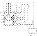
- FIG. 1 is a schematic view showing an example of a silicon single crystal manufacturing apparatus of the present invention.
- the silicon single crystal manufacturing apparatus 1 of the present invention the silicon single crystal 5 is pulled up from the raw material melt 4 heated by the heater 3 inside the chamber 2.
- the chamber 2 is cooled by the cooling means 6, and the inlet temperature, the outlet temperature, and the flow rate in the flow path through which the cooling medium used for cooling flows are measured by the inlet temperature measuring means 7, the outlet temperature measuring means 8, and the flow rate measuring means 9, respectively.
- the In the heat removal amount calculation means 10 the heat removal amount is calculated from the measured values of the inlet temperature, the outlet temperature, and the flow rate, and the heater power calculation unit 11 based on the heat removal amount calculates a heater power correction value.
- the crystal diameter of the silicon single crystal 5 being pulled is measured by the crystal diameter measuring means 12, and a heater power correction value is calculated from the measured value by the heater power calculation unit 13 based on the crystal diameter.
- the heater power output unit 15 controls the power value of the DC power source 14 based on these correction values, whereby the output of the heater 3 is controlled.
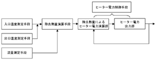
- FIG. 2 is a flowchart showing the flow from the inlet temperature, outlet temperature, and flow rate measuring means to the heater power control means.
- these are measured by the inlet temperature, outlet temperature, and flow rate measuring means, and the removed heat quantity from the chamber is calculated from the measured values by the removed heat quantity calculating means.
- a correction value of the heater power is calculated based on the amount of heat removed calculated by the heater power calculation unit, and the heater power is controlled by the heater power output unit.
- the heater power calculation unit and the heater power output unit are collectively referred to as heater power control means.
- the chamber 2 is divided for opening and closing, and the cooling means 6 is installed for each divided chamber. Accordingly, the inlet temperature, outlet temperature, and flow rate of the cooling medium flow path are measured for each of the divided chamber flow paths.
- the means for measuring the inlet temperature and outlet temperature of the flow path of the cooling medium is not particularly limited, and examples thereof include a thermocouple and a resistance temperature detector.
- the flow rate measuring means is not particularly limited, and examples thereof include an electromagnetic flow meter, a vortex flow meter, a Coriolis mass flow meter, and an ultrasonic flow meter.
- the amount of heat removed from the chamber is calculated from the measured values of the inlet temperature, outlet temperature, and flow rate.
- Heater power correction value heater power value-amount of heat removed (H)
- the silicon single crystal manufacturing apparatus of the present invention comprises means for measuring the crystal diameter during the straight body process, and means for calculating a correction value for the heater power based on the measured value of the crystal diameter. It is preferable. If such a means is provided, the heater power calculation unit based on the crystal diameter based on the measured value of the crystal diameter during crystal pulling as well as the heater power correction value based on the amount of heat removed as described above. A correction value can also be calculated. By controlling the heater power using these correction values in combination, the single crystal can be pulled at a crystal diameter and a crystal pulling speed that are closer to the target value.
- the heater power output unit actually controls the heater power.
- the heater power is controlled based on the amount of heat removed from the chamber calculated from the measured values of the temperature and flow rate of the cooling medium in addition to the measured values of the crystal diameter.
- the single crystal can be pulled at a crystal diameter and a crystal pulling speed closer to the target value.
- the above-described heater power control means is based on the operation result data of the amount of heat removed from the chamber obtained after pulling up the silicon single crystal, and the straight body process at the next pulling up It is preferable to have a function of calculating a set value pattern of the heater power inside.
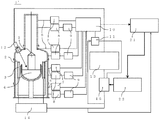
- FIG. 1 ′ of the present invention An example of a silicon single crystal manufacturing apparatus having such a function is shown in FIG.
- the silicon single crystal manufacturing apparatus 1 ′ of the present invention the silicon single crystal 5 is pulled up in the same manner as the silicon single crystal manufacturing apparatus shown in FIG.
- the removal heat quantity data obtained after pulling up the single crystal is accumulated in the operation result database 21, and the pattern calculation unit 22 based on the removal heat quantity is used as a basis for the setting value of the heater power during the straight body process at the next pulling up. (Hereinafter also referred to as a set power pattern) is calculated.
- the set power pattern is obtained by calculating the power value equivalent to the calculated amount of heat to be removed as the heater power set value or the heater power pattern correction value W obtained by the following formula as the heater power set value. It may be calculated by feedback.
- W W s ⁇ (H a ⁇ H b ) (W is the heater power pattern correction value, W s is the heater power value at the start of the straight body process, H a is the amount of heat removed at the start of the straight body process, and H b is the calculated amount of heat removed during the straight body process. Is shown.)
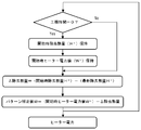
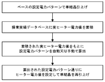
- FIG. 4 An example of the heater power calculation flow when calculating the set power pattern is shown in FIG.
- the pattern correction value W is calculated and fed back, the pattern correction value W at each straight body position is obtained along the flow shown in FIG. 4, and the set power pattern can be calculated based on this.
- the heater power at the next pulling can be set based on the data obtained after pulling the single crystal.
- the heater power is controlled based on the amount of heat removed from the chamber calculated from the measured values of the temperature and flow rate of the cooling medium in addition to the measured values of the crystal diameter.
- the single crystal can be pulled at a crystal diameter and a crystal pulling speed closer to the target value.
- the heater power at the next pulling can be set from the amount of heat removed calculated based on the data obtained after pulling the single crystal. Therefore, the quality of the obtained single crystal can be made desirable, and the production yield and productivity of the single crystal can be improved.
- Example 2 Using the silicon single crystal manufacturing apparatus of the present invention shown in FIG. 3, the silicon single crystal having a diameter of 300 mm and a straight body length of 1800 mm was pulled along the flow shown in FIG. First, the single crystal was pulled for the first time with the base set power pattern calculated based on the past heater power value data at the time of crystal pulling, and the removed heat amount data was accumulated in the operation result database.
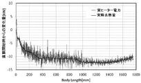
- FIG. 6 shows the actual heater power value and the actual removal heat amount data at the first pull-up. As shown in FIG. 6, the actual heater power value and the actual removal heat amount almost coincided with each other.
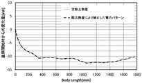
- the set power pattern of FIG. 7 was calculated based on the accumulated heat removal data.
- the set power pattern was calculated by setting a power value equivalent to the calculated amount of removed heat as the heater power set value.
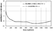
- FIG. 8 shows a comparison between the base set power pattern and the calculated set power pattern (FIG. 7).
- the power value of the heater was set according to the pattern of FIG. 7, and the silicon single crystal having a diameter of 300 mm and a straight body length of 1800 mm was pulled again.
- the control of the heater power during the pulling of the crystal is based on the amount of heat removed calculated from the temperature and flow rate of the cooling medium.
- the heater power correction value was calculated based on this, and this was also taken into account to control the heater power.
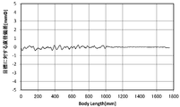
- the diameter of each obtained single crystal at each straight barrel position is measured, and a graph showing the amount of change in diameter is shown in FIG.
- a conventional silicon single crystal manufacturing apparatus 100 shown in FIG. 10 was used to pull up a silicon single crystal having a diameter of 300 mm and a straight body length of 1800 mm along the flow shown in FIG.
- the single crystal was pulled for the first time with the base set power pattern as in the example, and the actual heater power value was stored in the operation result database 21.
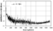
- the actual heater power value at the first pulling is shown in FIG.
- the set power pattern was calculated by the pattern calculation unit 101 based on the heater power.
- the power value of the heater was set according to the calculated pattern, and the silicon single crystal having a diameter of 300 mm and a straight body length of 1800 mm was pulled again.
- the control of the heater power during the pulling of the crystal is based on the conventional method of calculating the correction value of the heater power by the heater power calculation unit 13 based on the crystal diameter based on the crystal diameter during the pulling measured by the crystal diameter measuring means 12. Control was performed.
- FIG. 13 shows the diameter of the obtained single crystal measured at each straight cylinder position and expressed as a graph of the diameter change amount.
- the single crystal is pulled based on the set power pattern calculated based on the heat of removal, and is further pulled by the heat of removal.
- the single crystal was pulled using a conventional silicon single crystal manufacturing apparatus, the set power pattern was calculated based on the amount of heat removed, and the power value during the pulling was corrected.
- the diameter fluctuation from the target diameter was suppressed.
- the heater power is controlled based on the amount of heat removed from the chamber calculated from the measured values of the temperature and flow rate of the cooling medium, so that the target value can be further increased. It is clear that the single crystal can be pulled at a near crystal diameter and crystal pulling speed, and that the heater power at the next pulling can be set from the amount of heat removed calculated based on the data obtained after pulling the single crystal. became. Therefore, a single crystal having a desired quality can be obtained with high yield and high productivity.
- the present invention is not limited to the above embodiment.
- the above-described embodiment is an exemplification, and the present invention has any configuration that has substantially the same configuration as the technical idea described in the claims of the present invention and that exhibits the same effects. Are included in the technical scope.
Landscapes
- Chemical & Material Sciences (AREA)
- Engineering & Computer Science (AREA)
- Crystallography & Structural Chemistry (AREA)
- Materials Engineering (AREA)
- Metallurgy (AREA)
- Organic Chemistry (AREA)
- Crystals, And After-Treatments Of Crystals (AREA)
Abstract
Description
前記チャンバーを冷却する冷却媒体がチャンバー内を流通する流路における入口温度、出口温度、及び流量の測定手段、
前記入口温度、前記出口温度、及び前記流量の測定値をもとに前記チャンバーからの除去熱量を算出する演算手段、及び
前記算出した除去熱量をもとにヒーター電力を制御するヒーター電力制御手段、
を具備するシリコン単結晶製造装置を提供する。
W=Ws-(Ha-Hb)
(式中、Wはヒーター電力のパターン補正値、Wsは直胴工程開始時のヒーター電力値、Haは直胴工程開始時の除去熱量、Hbは算出した直胴工程中の除去熱量を示す。)
前記チャンバーを冷却する冷却媒体がチャンバー内を流通する流路における入口温度、出口温度、及び流量の測定手段、
前記入口温度、前記出口温度、及び前記流量の測定値をもとに前記チャンバーからの除去熱量を算出する演算手段、及び
前記算出した除去熱量をもとにヒーター電力を制御するヒーター電力制御手段、
を具備するシリコン単結晶製造装置である。
本発明のシリコン単結晶製造装置1では、チャンバー2内部のヒーター3によって加熱された原料融液4から、シリコン単結晶5が引上げられる。チャンバー2は冷却手段6によって冷却され、冷却に用いられる冷却媒体が流通する流路における入口温度、出口温度、流量はそれぞれ入口温度測定手段7、出口温度測定手段8、流量測定手段9によって測定される。除去熱量演算手段10では、入口温度、出口温度、流量の測定値から除去熱量が算出され、さらに除去熱量によるヒーター電力演算部11でヒーター電力の補正値が算出される。また、結晶直径測定手段12によって引上げ中のシリコン単結晶5の結晶直径が測定され、結晶直径によるヒーター電力演算部13で測定値からヒーター電力の補正値が算出される。これらの補正値をもとにヒーター電力出力部15が直流電源14の電力値を制御することで、ヒーター3の出力が制御される。
チャンバー2は開閉するために分割されており、冷却手段6は各分割されたチャンバー毎に設置されている。従って、冷却媒体の流路の入口温度、出口温度、及び流量は、各分割されたチャンバーの流路毎に測定される。
冷却媒体の流路の入口温度及び出口温度の測定手段としては、特に限定されないが、例えば熱電対及び測温抵抗体等が挙げられる。
また流量の測定手段としては、特に限定されないが、例えば電磁流量計、渦流量計、コリオリ式質量流量計、超音波流量計等が挙げられる。
次に、入口温度、出口温度、及び流量の測定値からチャンバーからの除去熱量を算出する。本発明において、チャンバーからの除去熱量Hは以下の式で表される。
H=ΔT×L×C×ρ
ΔT=Tout-Tin
(式中、Hは除去熱量(kW)、Toutは冷却媒体の出口温度(K)、Tinは冷却媒体の入口温度(K)、Lは冷却媒体の流量(l/sec)、Cは冷却媒体の比熱(kJ/kg・K)であり、水の場合C=4.1868、ρは冷却媒体の密度(kg/l)であり、25℃/大気圧における水の場合はρ=0.9970である。)
次に、除去熱量によるヒーター電力演算部で、上述のようにして算出した除去熱量をもとにヒーター電力の補正値を算出する。補正値は以下の式で求められる。
ヒーター電力の補正値=ヒーター電力値-除去熱量(H)
このような手段を具備するものであれば、上述の除去熱量によるヒーター電力の補正値だけでなく、結晶引上げ中の結晶直径の測定値をもとに結晶直径によるヒーター電力演算部でヒーター電力の補正値も算出することができる。これらの補正値を併用してヒーター電力の制御を行うことで、さらに目標値に近い結晶直径及び結晶引上げ速度で単結晶の引上げを行うことができる。
本発明のシリコン単結晶製造装置1’では、上述の図1に示されるシリコン単結晶製造装置と同様に、シリコン単結晶5の引上げを行う。単結晶引上げ後に得られた除去熱量データは操業実績データベース21に蓄積され、このデータをもとに除去熱量によるパターン算出部22で、次回引上げ時の直胴工程中のヒーター電力の設定値のパターン(以下、設定電力パターンともいう)を算出する。
W=Ws-(Ha-Hb)
(式中、Wはヒーター電力のパターン補正値、Wsは直胴工程開始時のヒーター電力値、Haは直胴工程開始時の除去熱量、Hbは算出した直胴工程中の除去熱量を示す。)
パターン補正値Wを算出しフィードバックさせる場合は、図4に示されるフローに沿って各直胴位置におけるパターン補正値Wを求め、これをもとにして設定電力パターンを算出することができる。
図3に示される本発明のシリコン単結晶製造装置を用い、図5に示されるフローに沿って、直径300mm、直胴部長さ1800mmのシリコン単結晶の引上げを行った。
まず、過去の結晶引上げ時のヒーター電力値の実績データをもとにして算出したベースの設定電力パターンで1度目の単結晶の引上げを行い、操業実績データベースに除去熱量データを蓄積した。1度目の引上げ時の実ヒーター電力値と実除去熱量データを図6に示す。図6に示されるように実ヒーター電力値と実除去熱量の数値はほぼ一致する結果が得られた。
次に、蓄積された除去熱量データをもとに、図7の設定電力パターンを算出した。なお、設定電力パターンは、算出した除去熱量と同等の電力値をヒーター電力の設定値として算出した。またここで、ベースの設定電力パターンと算出した設定電力パターン(図7)を比較したものを図8に示す。
次に、図7のパターン通りにヒーターの電力値を設定して、再度直径300mm、直胴部長さ1800mmのシリコン単結晶の引上げを行った。なお、結晶引上げ中のヒーター電力の制御は、引上げ中の結晶直径の測定値をもとにヒーター電力の補正値を算出する従来の制御に加え、冷却媒体の温度及び流量から算出した除去熱量をもとにヒーター電力の補正値を求め、これも加味してヒーター電力の制御を行った。
得られた単結晶の各直胴位置における直径を測定し、直径変化量のグラフとして表したものを図9に示す。
図10に示される従来のシリコン単結晶製造装置100を用い、図11に示されるフローに沿って、直径300mm、直胴部長さ1800mmのシリコン単結晶の引上げを行った。
まず、実施例と同様にベースの設定電力パターンで1度目の単結晶の引上げを行い、操業実績データベース21に実ヒーター電力値を蓄積した。1度目の引上げ時の実ヒーター電力値を図12に示す。次に、図12に示される実ヒーター電力値をもとに、ヒーター電力によるパターン算出部101で設定電力パターンを算出した。
次に、算出したパターン通りにヒーターの電力値を設定して、再度直径300mm、直胴部長さ1800mmのシリコン単結晶の引上げを行った。なお、結晶引上げ中のヒーター電力の制御は、結晶直径測定手段12によって測定された引上げ中の結晶直径をもとに、結晶直径によるヒーター電力演算部13でヒーター電力の補正値を算出する従来の制御を行った。
得られた単結晶の各直胴位置における直径を測定し、直径変化量のグラフとして表したものを図13に示す。
Claims (5)
- 原料を加熱するヒーターを内部に有するチャンバー及び冷却媒体によって前記チャンバーを冷却する手段を有するCZ法によるシリコン単結晶製造装置であって、
前記チャンバーを冷却する冷却媒体がチャンバー内を流通する流路における入口温度、出口温度、及び流量の測定手段、
前記入口温度、前記出口温度、及び前記流量の測定値をもとに前記チャンバーからの除去熱量を算出する演算手段、及び
前記算出した除去熱量をもとにヒーター電力を制御するヒーター電力制御手段、
を具備するものであることを特徴とするシリコン単結晶製造装置。 - 前記シリコン単結晶製造装置が、直胴工程中の結晶直径を測定する手段、及び前記結晶直径の測定値をもとに前記ヒーター電力の補正値を算出する手段を具備するものであることを特徴とする請求項1に記載のシリコン単結晶製造装置。
- 前記ヒーター電力制御手段が、シリコン単結晶引上げ後に得られた前記チャンバーからの除去熱量の操業実績データをもとに、次回引上げ時の直胴工程中のヒーター電力の設定値のパターンを算出する機能を具備するものであること特徴とする請求項1又は請求項2に記載のシリコン単結晶製造装置。
- 前記次回引上げ時の直胴工程中のヒーター電力の設定値のパターンが、前記算出した除去熱量と同等の電力値をヒーター電力の設定値としたものであることを特徴とする請求項3に記載のシリコン単結晶製造装置。
- 前記次回引上げ時の直胴工程中のヒーター電力の設定値のパターンが、以下の式で求められるヒーター電力のパターン補正値Wをヒーター電力の設定値にフィードバックさせたものであることを特徴とする請求項3に記載のシリコン単結晶製造装置。
W=Ws-(Ha-Hb)
(式中、Wはヒーター電力のパターン補正値、Wsは直胴工程開始時のヒーター電力値、Haは直胴工程開始時の除去熱量、Hbは算出した直胴工程中の除去熱量を示す。)
Priority Applications (4)
| Application Number | Priority Date | Filing Date | Title |
|---|---|---|---|
| KR1020167021586A KR102241284B1 (ko) | 2014-02-12 | 2015-02-03 | 실리콘 단결정 제조장치 |
| DE112015000435.1T DE112015000435B4 (de) | 2014-02-12 | 2015-02-03 | Vorrichtung zum Herstellen eines Silizium-Einkristalls |
| US15/112,653 US10036100B2 (en) | 2014-02-12 | 2015-02-03 | Apparatus for producing silicon single crystal |
| CN201580008300.7A CN106029958B (zh) | 2014-02-12 | 2015-02-03 | 单晶硅制造装置 |
Applications Claiming Priority (2)
| Application Number | Priority Date | Filing Date | Title |
|---|---|---|---|
| JP2014024363A JP6197680B2 (ja) | 2014-02-12 | 2014-02-12 | シリコン単結晶製造装置 |
| JP2014-024363 | 2014-02-12 |
Publications (1)
| Publication Number | Publication Date |
|---|---|
| WO2015122145A1 true WO2015122145A1 (ja) | 2015-08-20 |
Family
ID=53799898
Family Applications (1)
| Application Number | Title | Priority Date | Filing Date |
|---|---|---|---|
| PCT/JP2015/000453 Ceased WO2015122145A1 (ja) | 2014-02-12 | 2015-02-03 | シリコン単結晶製造装置 |
Country Status (6)
| Country | Link |
|---|---|
| US (1) | US10036100B2 (ja) |
| JP (1) | JP6197680B2 (ja) |
| KR (1) | KR102241284B1 (ja) |
| CN (1) | CN106029958B (ja) |
| DE (1) | DE112015000435B4 (ja) |
| WO (1) | WO2015122145A1 (ja) |
Cited By (1)
| Publication number | Priority date | Publication date | Assignee | Title |
|---|---|---|---|---|
| CN115640983A (zh) * | 2022-11-18 | 2023-01-24 | 浙江晶盛机电股份有限公司 | 功率调整方法、装置、计算机设备和存储介质 |
Families Citing this family (6)
| Publication number | Priority date | Publication date | Assignee | Title |
|---|---|---|---|---|
| JP6515791B2 (ja) * | 2015-11-26 | 2019-05-22 | 株式会社Sumco | シリコン単結晶の製造方法 |
| CN107151817A (zh) * | 2016-03-03 | 2017-09-12 | 上海新昇半导体科技有限公司 | 单晶硅的生长方法及其制备的单晶硅锭 |
| JP6828674B2 (ja) * | 2017-12-20 | 2021-02-10 | 株式会社Sumco | クリーニング方法、シリコン単結晶の製造方法、および、クリーニング装置 |
| JP7021626B2 (ja) * | 2018-10-03 | 2022-02-17 | 株式会社Sumco | 原料供給方法およびシリコン単結晶の製造方法 |
| KR102737962B1 (ko) * | 2022-10-18 | 2024-12-05 | 한국원자력연구원 | 단결정 성장 장치 및 방법 |
| CN116145240A (zh) * | 2022-12-30 | 2023-05-23 | 上海新昇半导体科技有限公司 | 一种晶体生长的控制方法、装置、系统及计算机存储介质 |
Citations (3)
| Publication number | Priority date | Publication date | Assignee | Title |
|---|---|---|---|---|
| JPH1121120A (ja) * | 1997-07-02 | 1999-01-26 | Sharp Corp | 多結晶半導体の製造方法および製造装置 |
| JP2008105873A (ja) * | 2006-10-24 | 2008-05-08 | Shin Etsu Handotai Co Ltd | 単結晶製造装置及び単結晶の製造方法 |
| JP2008127216A (ja) * | 2006-11-16 | 2008-06-05 | Sumco Techxiv株式会社 | 半導体単結晶製造方法 |
Family Cites Families (16)
| Publication number | Priority date | Publication date | Assignee | Title |
|---|---|---|---|---|
| US3701686A (en) * | 1966-02-11 | 1972-10-31 | North American Rockwell | Solid state cell construction |
| US6117462A (en) * | 1998-03-12 | 2000-09-12 | Nucycle Therapy, Inc. | Nutritional supplements |
| TW588127B (en) * | 2000-02-01 | 2004-05-21 | Komatsu Denshi Kinzoku Kk | Apparatus for pulling single crystal by CZ method |
| KR20020081287A (ko) * | 2000-02-01 | 2002-10-26 | 엠이엠씨 일렉트로닉 머티리얼즈 인코포레이티드 | 성장 속도 및 직경 편차를 최소화하도록 실리콘 결정의성장을 제어하는 방법 |
| US8147613B2 (en) * | 2002-11-12 | 2012-04-03 | Memc Electronic Materials, Inc. | Crystal puller and method for growing a monocrystalline ingot |
| US7635414B2 (en) * | 2003-11-03 | 2009-12-22 | Solaicx, Inc. | System for continuous growing of monocrystalline silicon |
| JP4661204B2 (ja) | 2004-12-16 | 2011-03-30 | 信越半導体株式会社 | 単結晶の製造方法およびアニールウェーハの製造方法ならびにアニールウェーハ |
| CN100383295C (zh) | 2006-03-31 | 2008-04-23 | 浙江大学 | 直拉式晶体生长炉自动控制方法 |
| JP5125003B2 (ja) | 2006-06-26 | 2013-01-23 | 信越半導体株式会社 | シリコン単結晶の製造システムおよびこれを用いたシリコン単結晶の製造方法 |
| CN105477897B (zh) | 2007-03-14 | 2017-09-19 | 三菱化学株式会社 | 析晶方法及用于其的析晶装置 |
| JP5104129B2 (ja) | 2007-08-31 | 2012-12-19 | 信越半導体株式会社 | 単結晶直径の検出方法および単結晶引上げ装置 |
| KR101005988B1 (ko) * | 2008-12-22 | 2011-01-05 | 주식회사 실트론 | 실리콘 단결정 잉곳 제조장치의 냉각 모듈 및 냉각 방법 |
| JP5026549B2 (ja) | 2010-04-08 | 2012-09-12 | シャープ株式会社 | 加熱制御システム、それを備えた成膜装置、および温度制御方法 |
| CN202099412U (zh) | 2011-06-01 | 2012-01-04 | 浙江昱辉阳光能源有限公司 | 多晶铸锭炉及其热交换装置 |
| JP5776587B2 (ja) * | 2012-02-24 | 2015-09-09 | 信越半導体株式会社 | 単結晶製造方法 |
| US9127377B2 (en) * | 2012-08-21 | 2015-09-08 | Babcock Noell Gmbh | Generating a homogeneous magnetic field while pulling a single crystal from molten semiconductor material |
-
2014
- 2014-02-12 JP JP2014024363A patent/JP6197680B2/ja active Active
-
2015
- 2015-02-03 US US15/112,653 patent/US10036100B2/en active Active
- 2015-02-03 CN CN201580008300.7A patent/CN106029958B/zh active Active
- 2015-02-03 KR KR1020167021586A patent/KR102241284B1/ko active Active
- 2015-02-03 WO PCT/JP2015/000453 patent/WO2015122145A1/ja not_active Ceased
- 2015-02-03 DE DE112015000435.1T patent/DE112015000435B4/de active Active
Patent Citations (3)
| Publication number | Priority date | Publication date | Assignee | Title |
|---|---|---|---|---|
| JPH1121120A (ja) * | 1997-07-02 | 1999-01-26 | Sharp Corp | 多結晶半導体の製造方法および製造装置 |
| JP2008105873A (ja) * | 2006-10-24 | 2008-05-08 | Shin Etsu Handotai Co Ltd | 単結晶製造装置及び単結晶の製造方法 |
| JP2008127216A (ja) * | 2006-11-16 | 2008-06-05 | Sumco Techxiv株式会社 | 半導体単結晶製造方法 |
Cited By (1)
| Publication number | Priority date | Publication date | Assignee | Title |
|---|---|---|---|---|
| CN115640983A (zh) * | 2022-11-18 | 2023-01-24 | 浙江晶盛机电股份有限公司 | 功率调整方法、装置、计算机设备和存储介质 |
Also Published As
| Publication number | Publication date |
|---|---|
| CN106029958A (zh) | 2016-10-12 |
| KR20160120725A (ko) | 2016-10-18 |
| JP6197680B2 (ja) | 2017-09-20 |
| US20160333496A1 (en) | 2016-11-17 |
| CN106029958B (zh) | 2018-10-26 |
| KR102241284B1 (ko) | 2021-04-16 |
| JP2015151283A (ja) | 2015-08-24 |
| DE112015000435B4 (de) | 2022-07-21 |
| DE112015000435T5 (de) | 2016-10-06 |
| US10036100B2 (en) | 2018-07-31 |
Similar Documents
| Publication | Publication Date | Title |
|---|---|---|
| JP6197680B2 (ja) | シリコン単結晶製造装置 | |
| JP6583142B2 (ja) | シリコン単結晶の製造方法及び装置 | |
| JP6324907B2 (ja) | 溶融体から結晶シートを成長させる装置及び方法 | |
| KR101385997B1 (ko) | 단결정 제조장치 및 단결정 제조방법 | |
| JP6222056B2 (ja) | シリコン単結晶の温度の推定方法及びシリコン単結晶の製造方法 | |
| TW200815628A (en) | Single crystal manufacturing apparatus and method | |
| KR101862157B1 (ko) | 단결정 실리콘 잉곳 제조 방법 및 장치 | |
| JP5353295B2 (ja) | 単結晶の製造方法 | |
| TW201938851A (zh) | 矽融液的對流圖案推測方法、矽單結晶的氧濃度推測方法、矽單結晶的製造方法及矽單結晶的拉引裝置 | |
| CN112074626B (zh) | 硅熔液的对流模式控制方法及单晶硅的制造方法 | |
| JP7626145B2 (ja) | シリコン単結晶の酸素濃度推定方法、シリコン単結晶の製造方法及びシリコン単結晶製造装置 | |
| KR101625433B1 (ko) | 단결정 실리콘 잉곳 제조 방법 및 장치 | |
| KR20150053121A (ko) | 실리콘 단결정 잉곳 제조 장치 및 제조 방법 | |
| JP2012006802A (ja) | シリコン単結晶の製造方法及び製造装置 | |
| JP2826085B2 (ja) | 単結晶引上炉の液温制御方法 | |
| TW202138634A (zh) | 單結晶製造系統及單結晶製造方法 | |
| KR101366726B1 (ko) | 단결정 실리콘 잉곳 제조 장치 및 방법 | |
| JP4407539B2 (ja) | 単結晶インゴットの引上げ速度のシミュレーション方法 | |
| KR101340082B1 (ko) | 단결정 실리콘 잉곳 제조 장치 | |
| JP5333396B2 (ja) | 単結晶の製造方法及び単結晶製造装置 | |
| KR20140092507A (ko) | 잉곳 성장 장치 및 잉곳 성장 방법 | |
| JP2016169126A (ja) | 結晶の製造方法 | |
| JP2015189598A (ja) | 単結晶育成装置 |
Legal Events
| Date | Code | Title | Description |
|---|---|---|---|
| 121 | Ep: the epo has been informed by wipo that ep was designated in this application |
Ref document number: 15748532 Country of ref document: EP Kind code of ref document: A1 |
|
| WWE | Wipo information: entry into national phase |
Ref document number: 15112653 Country of ref document: US |
|
| ENP | Entry into the national phase |
Ref document number: 20167021586 Country of ref document: KR Kind code of ref document: A |
|
| WWE | Wipo information: entry into national phase |
Ref document number: 112015000435 Country of ref document: DE |
|
| 122 | Ep: pct application non-entry in european phase |
Ref document number: 15748532 Country of ref document: EP Kind code of ref document: A1 |