WO2015115625A1 - ガスタービン、ガスタービンの制御装置、ガスタービンの冷却方法 - Google Patents
ガスタービン、ガスタービンの制御装置、ガスタービンの冷却方法 Download PDFInfo
- Publication number
- WO2015115625A1 WO2015115625A1 PCT/JP2015/052770 JP2015052770W WO2015115625A1 WO 2015115625 A1 WO2015115625 A1 WO 2015115625A1 JP 2015052770 W JP2015052770 W JP 2015052770W WO 2015115625 A1 WO2015115625 A1 WO 2015115625A1
- Authority
- WO
- WIPO (PCT)
- Prior art keywords
- setting value
- valve opening
- temperature
- opening setting
- valve
- Prior art date
- Legal status (The legal status is an assumption and is not a legal conclusion. Google has not performed a legal analysis and makes no representation as to the accuracy of the status listed.)
- Ceased
Links
Images


Classifications
-
- F—MECHANICAL ENGINEERING; LIGHTING; HEATING; WEAPONS; BLASTING
- F02—COMBUSTION ENGINES; HOT-GAS OR COMBUSTION-PRODUCT ENGINE PLANTS
- F02C—GAS-TURBINE PLANTS; AIR INTAKES FOR JET-PROPULSION PLANTS; CONTROLLING FUEL SUPPLY IN AIR-BREATHING JET-PROPULSION PLANTS
- F02C7/00—Features, components parts, details or accessories, not provided for in, or of interest apart form groups F02C1/00 - F02C6/00; Air intakes for jet-propulsion plants
- F02C7/12—Cooling of plants
- F02C7/16—Cooling of plants characterised by cooling medium
- F02C7/18—Cooling of plants characterised by cooling medium the medium being gaseous, e.g. air
-
- F—MECHANICAL ENGINEERING; LIGHTING; HEATING; WEAPONS; BLASTING
- F01—MACHINES OR ENGINES IN GENERAL; ENGINE PLANTS IN GENERAL; STEAM ENGINES
- F01D—NON-POSITIVE DISPLACEMENT MACHINES OR ENGINES, e.g. STEAM TURBINES
- F01D11/00—Preventing or minimising internal leakage of working-fluid, e.g. between stages
- F01D11/08—Preventing or minimising internal leakage of working-fluid, e.g. between stages for sealing space between rotor blade tips and stator
- F01D11/14—Adjusting or regulating tip-clearance, i.e. distance between rotor-blade tips and stator casing
- F01D11/20—Actively adjusting tip-clearance
- F01D11/24—Actively adjusting tip-clearance by selectively cooling-heating stator or rotor components
-
- F—MECHANICAL ENGINEERING; LIGHTING; HEATING; WEAPONS; BLASTING
- F01—MACHINES OR ENGINES IN GENERAL; ENGINE PLANTS IN GENERAL; STEAM ENGINES
- F01D—NON-POSITIVE DISPLACEMENT MACHINES OR ENGINES, e.g. STEAM TURBINES
- F01D5/00—Blades; Blade-carrying members; Heating, heat-insulating, cooling or antivibration means on the blades or the members
- F01D5/02—Blade-carrying members, e.g. rotors
- F01D5/08—Heating, heat-insulating or cooling means
- F01D5/081—Cooling fluid being directed on the side of the rotor disc or at the roots of the blades
-
- F—MECHANICAL ENGINEERING; LIGHTING; HEATING; WEAPONS; BLASTING
- F01—MACHINES OR ENGINES IN GENERAL; ENGINE PLANTS IN GENERAL; STEAM ENGINES
- F01D—NON-POSITIVE DISPLACEMENT MACHINES OR ENGINES, e.g. STEAM TURBINES
- F01D9/00—Stators
- F01D9/06—Fluid supply conduits to nozzles or the like
- F01D9/065—Fluid supply or removal conduits traversing the working fluid flow, e.g. for lubrication-, cooling-, or sealing fluids
-
- F—MECHANICAL ENGINEERING; LIGHTING; HEATING; WEAPONS; BLASTING
- F02—COMBUSTION ENGINES; HOT-GAS OR COMBUSTION-PRODUCT ENGINE PLANTS
- F02C—GAS-TURBINE PLANTS; AIR INTAKES FOR JET-PROPULSION PLANTS; CONTROLLING FUEL SUPPLY IN AIR-BREATHING JET-PROPULSION PLANTS
- F02C6/00—Plural gas-turbine plants; Combinations of gas-turbine plants with other apparatus; Adaptations of gas-turbine plants for special use
- F02C6/04—Gas-turbine plants providing heated or pressurised working fluid for other apparatus, e.g. without mechanical power output
- F02C6/06—Gas-turbine plants providing heated or pressurised working fluid for other apparatus, e.g. without mechanical power output providing compressed gas
- F02C6/08—Gas-turbine plants providing heated or pressurised working fluid for other apparatus, e.g. without mechanical power output providing compressed gas the gas being bled from the gas-turbine compressor
-
- F—MECHANICAL ENGINEERING; LIGHTING; HEATING; WEAPONS; BLASTING
- F02—COMBUSTION ENGINES; HOT-GAS OR COMBUSTION-PRODUCT ENGINE PLANTS
- F02C—GAS-TURBINE PLANTS; AIR INTAKES FOR JET-PROPULSION PLANTS; CONTROLLING FUEL SUPPLY IN AIR-BREATHING JET-PROPULSION PLANTS
- F02C9/00—Controlling gas-turbine plants; Controlling fuel supply in air- breathing jet-propulsion plants
- F02C9/16—Control of working fluid flow
- F02C9/18—Control of working fluid flow by bleeding, bypassing or acting on variable working fluid interconnections between turbines or compressors or their stages
-
- F—MECHANICAL ENGINEERING; LIGHTING; HEATING; WEAPONS; BLASTING
- F05—INDEXING SCHEMES RELATING TO ENGINES OR PUMPS IN VARIOUS SUBCLASSES OF CLASSES F01-F04
- F05D—INDEXING SCHEME FOR ASPECTS RELATING TO NON-POSITIVE-DISPLACEMENT MACHINES OR ENGINES, GAS-TURBINES OR JET-PROPULSION PLANTS
- F05D2270/00—Control
- F05D2270/30—Control parameters, e.g. input parameters
- F05D2270/303—Temperature
Definitions
- the present invention provides, for example, a gas turbine that supplies fuel to compressed high-temperature, high-pressure air and burns, and supplies the generated combustion gas to a turbine to obtain rotational power, a control device for the gas turbine, and a gas turbine It is related with the cooling method.
- General gas turbine is composed of a compressor, a combustor, and a turbine.
- the compressor compresses the air taken in from the air intake port into high-temperature and high-pressure compressed air.
- the combustor obtains high-temperature and high-pressure combustion gas by supplying fuel to the compressed air and burning it.
- the turbine is driven by this combustion gas, and drives a generator connected on the same axis.
- the turbine in this gas turbine is configured by alternately arranging a plurality of stationary blades and moving blades along the flow direction of the combustion gas in the passenger compartment, and the combustion gas generated in the combustor is a plurality of stationary blades.
- the rotor is driven and rotated by passing through the blades and the moving blades, and the generator connected to the rotor is driven.
- Patent Document 1 As such a gas turbine, there is one described in Patent Document 1, for example.
- the flow rate control valve provided in the external piping of the cooling air, the temperature detector for measuring the air temperature in the disk cavity, and the flow rate based on the detection signal from the temperature detector.
- Valve adjusting means for adjusting the opening of the control valve is provided. Therefore, by adjusting the opening degree of the flow rate control valve based on the air temperature in the disk cavity, the gas turbine cooling air amount can be accurately kept at the necessary minimum amount.
- such control makes it difficult to properly maintain the air temperature in the disk cavity at an appropriate temperature during a transition period in which the output (load) increases when the gas turbine is started.
- the opening of the flow control valve is PI controlled based on the air temperature in the disk cavity, the air temperature fluctuates (increases and decreases) every time the opening is changed, so the flow control valve opens and closes in a short time. It will operate and control will become complicated.
- the present invention solves the above-described problems, and provides a gas turbine, a gas turbine control device, and a gas turbine cooling method capable of appropriately controlling the air temperature of the disk cavity and simplifying the control.
- the purpose is to provide.
- a gas turbine includes a compressor that compresses air, a combustor that mixes and burns compressed air and fuel compressed by the compressor, and combustion generated by the combustor.
- a turbine for obtaining rotational power by gas; a cooling air supply path for supplying air extracted from the compressor to a disk cavity of the turbine; an on-off valve provided in the cooling air supply path; and an ambient temperature of the disk cavity.
- the gas turbine comprising: a temperature measuring unit to measure; and a control device that adjusts an opening degree of the on-off valve based on an ambient temperature measured by the temperature measuring unit.
- the control device is a first valve in the on-off valve.
- the control device applies the first valve opening setting value when the atmospheric temperature of the disk cavity is lower than the switching temperature, and applies the second valve opening setting value when the atmospheric temperature of the disk cavity is higher than the switching temperature. To do. That is, since two kinds of valve opening setting values are switched and used, the air temperature of the disk cavity can be properly controlled, and the control is simplified without the on-off valve opening and closing in a short time. be able to.
- the control device changes the speed at which the first valve opening setting value is switched from the first valve opening setting value to the second valve opening setting value from the second valve opening setting value. It is characterized by setting faster than the speed of switching to the value.
- the opening degree of the opening / closing valve is increased, the opening / closing valve is operated quickly, and when the opening degree of the opening / closing valve is decreased, the opening / closing valve is operated slowly. Therefore, when the atmospheric temperature of the disk cavity rises, the temperature can be quickly lowered, so that the operation can be continued without damaging the gas turbine. Further, when the ambient temperature of the disk cavity is lowered, the temperature is slowly raised, so that hunting of the on-off valve can be suppressed.
- the control device switches from the second valve opening setting value to the first valve opening setting value when the load reaches a predetermined load set in advance after startup. .
- the atmospheric temperature of the disk cavity can be adjusted with high accuracy.
- the control device when the control device reaches the predetermined load, the control device switches from the second valve opening setting value to the first valve opening setting value after a predetermined time has elapsed. It is characterized by.
- the predetermined load is a load that is at least 90% or more of the total load.
- the ambient temperature of the disk cavity can be adjusted with high accuracy and safely.
- the switching temperature has a first switching temperature and a second switching temperature higher than the first switching temperature, and the second valve opens when the ambient temperature becomes higher than the second switching temperature.
- the first valve opening setting value is applied.
- the control device for a gas turbine includes a compressor that compresses air, a combustor that mixes and burns compressed air and fuel compressed by the compressor, and a combustion gas generated by the combustor.
- a turbine for obtaining power, a cooling air supply path for supplying compressed air extracted from the compressor to a disk cavity of the turbine, an on-off valve provided in the cooling air supply path, and an ambient temperature of the disk cavity are measured.
- the opening degree of the on-off valve can be adjusted based on the atmospheric temperature measured by the temperature measuring unit, and the first valve opening setting value and the first value in the on-off valve
- a second valve opening setting value larger than the valve opening setting value can be set, and the first valve opening setting value when the ambient temperature is lower than a preset switching temperature. Applied, the ambient temperature is applied to the second valve opening setting value when higher than the switching temperature, it is characterized in.
- the air temperature of the disk cavity can be properly controlled, and the control is simplified without the on-off valve opening and closing in a short time. be able to.
- the gas turbine cooling method of the present invention comprises a compressor that compresses air, a combustor that mixes and burns compressed air and fuel compressed by the compressor, and a combustion gas generated by the combustor.
- a turbine for obtaining power ; a cooling air supply path for supplying compressed air extracted from the compressor to a disk cavity of the turbine; and an on-off valve provided in the cooling air supply path; and an atmosphere of the disk cavity
- the gas turbine cooling method of adjusting the opening of the on-off valve according to temperature the step of measuring the ambient temperature of the disk cavity, and the on-off valve when the ambient temperature is lower than a preset switching temperature Applying a first valve opening setting value preset as the opening of the valve, and the on-off valve when the ambient temperature is higher than the switching temperature Applying a second valve opening setting value larger than the first valve opening setting value as the opening, it is characterized in that it has a.
- the air temperature of the disk cavity can be properly controlled, and the control is simplified without the on-off valve opening and closing in a short time. be able to.
- the first valve opening setting value for the on-off valve and the second valve opening setting value that is larger than the first valve opening setting value.
- the first valve opening setting value is applied, and when the atmospheric temperature is higher than the switching temperature, the second valve opening setting value is set. Because it is applied, two kinds of valve opening setting values are switched and used, so that the air temperature of the disk cavity can be controlled appropriately, and the control is simplified without the on-off valve opening and closing in a short time.
- FIG. 1 is a schematic configuration diagram illustrating a gas turbine according to the present embodiment.
- FIG. 2 is a graph showing the opening degree of the on-off valve with respect to the intake temperature of the gas turbine.
- FIG. 3 is a graph showing the opening degree of the bypass valve with respect to the intake temperature of the gas turbine.
- FIG. 4 is a flowchart showing cooling control of the gas turbine.
- FIG. 5 is a time chart showing the cooling control of the gas turbine.
- FIG. 1 is a schematic configuration diagram showing a gas turbine according to the present embodiment.
- the gas turbine 10 includes a compressor 11, a combustor 12, and a turbine 13.
- the gas turbine 10 is connected to a generator 14 on the same axis.
- the generator 14 as an electric motor, the gas turbine 10 can be started and the generator 14 can be driven by the power after starting. Power can be generated by driving.
- the compressor 11 has an air intake 21 for taking in air, and an inlet guide vane (IGV: Inlet Guide Vane) (not shown), a plurality of stationary blades, and a plurality of moving blades are in the air flow direction (in the compressor casing 22).
- IGV Inlet Guide Vane
- the bleed chambers 23 are provided on the outer side of the rotor in the direction of the rotor (which will be described later).
- the compressor 11 can generate high-temperature and high-pressure compressed air by compressing the air taken in from the air intake 21.
- the combustor 12 generates fuel gas by supplying fuel to the high-temperature and high-pressure compressed air compressed by the compressor 11 and burning the compressed air.
- a plurality of stationary blades 25 and a plurality of moving blades 26 are alternately arranged in a turbine casing 24 in the flow direction of combustion gas (the axial direction of a rotor described later).
- the exhaust chamber is arrange
- the turbine 13 is driven by the combustion gas from the combustor 12 and drives a generator 14 connected coaxially.
- the compressor 11, the combustor 12, and the turbine 13 have a rotor shaft 27 disposed so as to penetrate through the center thereof.
- the rotor shaft 27 has an end portion on the compressor 11 side supported rotatably by a bearing portion 28, and an end portion on the turbine 13 side supported rotatably by a bearing portion 29.
- the rotor shaft 27 is fixed by stacking a plurality of disks on which the moving blades are mounted in the compressor 11 and a plurality of disks on which the moving blades 26 are mounted in the turbine 13. Is fixed.
- the air taken in from the air intake 21 by the compressor 11 passes through the inlet guide blade, the plurality of stationary blades, and the moving blade, and is compressed into high-temperature and high-pressure compressed air.
- a predetermined fuel is supplied to the compressed air in the combustor 12 and burned.
- the high-temperature and high-pressure combustion gas generated by the combustor 12 passes through the plurality of stationary blades 25 and the moving blades 26 in the turbine 13 to drive and rotate the rotor shaft 27.
- the generator 14 connected is driven.
- a plurality of stationary blades 25 are fixed at equal intervals along the circumferential direction on the inner wall portion of the turbine casing 24.
- a plurality of rotor blades 26 are fixed to the outer peripheral portion of the rotor shaft 27 at equal intervals along the circumferential direction.
- the stationary blades 25 and the moving blades 26 are alternately arranged on the rotor shaft 27 along the axial direction in the combustion gas passage.
- a gap, that is, a disk cavity 31 is provided between the distal end portion of each stationary blade 25 and the outer peripheral portion of the rotor shaft 27, and a seal member is provided from the outer peripheral portion of the rotor shaft 27 toward the distal end portion of the stationary blade 25. Is provided. Then, the cooling air supplied in the stationary blade 25 is discharged from the tip of the stationary blade 25 to the upstream side of the combustion gas passage, thereby ensuring the sealing performance by the sealing member.
- this is prevented, and the atmospheric temperature of the disk cavity 31 is kept appropriate by adjusting the amount of cooling air supplied to the disk cavity 31.
- a cooling air supply path 41 is provided for supplying compressed air extracted from the extraction chamber 23 of the compressor 11 to the disk cavity 31 of the turbine 13 as cooling air.
- the cooling air supply path 41 has a main passage 42 and a branch passage 43 that are arranged in parallel.
- a cooler side valve 44 and a cooler 45 are provided in the main passage 42, and a bypass valve 46 is provided in the branch passage 43.
- An orifice 47 is provided downstream of the main passage 42 and the branch passage 43 in the cooling air supply passage 41.
- FIG. 1 only one cooling air supply path 41 for supplying the compressed air extracted from the extraction chamber 23 of the compressor 11 to the disk cavity 31 of the turbine 13 as cooling air is shown.
- a plurality of cooling air supply paths 41 are provided for supplying the compressed air extracted from the extraction chambers 23 of each stage as cooling air to the disk cavities 31 of each stage of the turbine 13.
- the turbine 13 is provided with a temperature measurement unit 48 that measures the ambient temperature (DCT) of the disk cavity 31.
- the control device 49 can adjust the opening degree of the cooler side valve 44 based on the ambient temperature of the disk cavity 31 measured by the temperature measuring unit 48. That is, the control device 49 increases the flow rate of the cooling air and adjusts the temperature of the cooling cavity side valve 44 by increasing the opening of the cooler side valve 44 when the atmospheric temperature of the disk cavity 31 measured by the temperature measuring unit 48 increases. And the ambient temperature of the disk cavity 31 is lowered.
- control device 49 has a first valve opening setting value and a second valve opening setting value as valve opening setting values for the cooler side valve 44.
- the second valve opening setting value is larger than the first valve opening setting value.
- the control device 49 applies the first valve opening setting value when the atmospheric temperature of the disk cavity 31 is lower than a preset switching temperature, and the atmospheric temperature of the disk cavity 31 is higher than the switching temperature. Sometimes the second valve opening set value is applied.
- FIG. 2 is a graph showing the opening degree of the on-off valve with respect to the intake temperature of the gas turbine
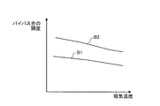
- FIG. 3 is a graph showing the opening degree of the bypass valve with respect to the intake temperature of the gas turbine.
- the valve opening setting value in the cooler side valve 44 is a map set as the opening degree of the cooler side valve 44 relative to the intake temperature of the gas turbine, and the ambient temperature ( DCT) is set as a first valve opening setting value A1 and a second valve opening setting value A2.
- the first valve opening setting value A1 is a map in which the opening degree of the cooler side valve 44 increases from a constant state as the intake temperature of the gas turbine increases.
- the second valve opening setting value A2 is such that the opening degree of the cooler side valve 44 is proportionally increased with respect to the rise in the intake temperature of the gas turbine.
- the second valve opening setting value A2 is a map in which the opening degree of the cooler side valve 44 is set larger than the first valve opening setting value A1.
- control device 49 has the first valve opening setting value and the second valve opening setting value as the valve opening setting values in the cooler side valve 44, but is not limited to this configuration.
- the control device 49 may have a first valve opening setting value B1 and a second valve opening setting value B2 as valve opening setting values for the bypass valve 46.
- the control device 49 may have first valve opening setting values A1, B1 and second valve opening setting values A2, B2 as valve opening setting values in the cooler side valve 44 and the bypass valve 46. .
- the main passage 42 and the branch passage 43 that are in parallel to the cooling air supply passage 41 are provided, the cooler side valve 44 and the cooler 45 are provided in the main passage 42, and the bypass valve 46 is provided in the branch passage 43. It is not limited to the configuration.
- the bypass valve 46 may be omitted from the branch passage 43.
- control device 49 changes the speed (second change rate of the opening / closing speed) for switching from the first valve opening setting value A1 to the second valve opening setting value A2 from the second valve opening setting value A2 to the first valve.
- the speed is set faster (larger) than the speed (first change rate of the opening / closing speed) for switching to the opening setting value A1. That is, when switching from the first valve opening setting value A1 to the second valve opening setting value A2, the on-off valve 45 is slowly closed and the second valve opening setting value A2 is changed to the first valve opening setting value A2.
- switching to A1 it opens quickly.
- the control device 49 when the load reaches a predetermined load that is set in advance (for example, a load that is at least 90% or more of the total load of the gas turbine 10), the second valve opening setting value. Switching from A2 to the first valve opening setting value A1 is made. Furthermore, it is preferable that the control device 49 switches from the second valve opening setting value A2 to the first valve opening setting value A1 after a predetermined time has elapsed when the predetermined load is reached.
- control apparatus 49 is 2nd switching temperature higher than 1st switching temperature T1 and 1st switching temperature T1 as switching temperature for switching 1st valve opening setting value A1 and 2nd valve opening setting value A2.
- the second valve opening setting value A2 is applied.
- the first valve is set.
- the opening setting value A1 is applied.
- the gas turbine cooling method adjusts the opening degree of the cooler side valve 44 in accordance with the ambient temperature DCT of the disk cavity 31, measures the ambient temperature DCT of the disk cavity 31, and the ambient temperature.
- FIG. 4 is a flowchart showing gas turbine cooling control
- FIG. 5 is a time chart showing gas turbine cooling control.
- step S11 the gas turbine (GT) 10 is started in step S11.
- step S12 the cooler side valve 44 is fully opened. Then, in the gas turbine 10, the rotation speed of the rotor shaft 27 increases, and the load (output) increases.
- step S13 it is determined whether the gas turbine (GT) load has reached a predetermined load (for example, 95%) set in advance. If it is determined (No) that the GT load has not reached the predetermined load (95%), this state is maintained.
- a predetermined load for example, 95%
- step S14 the cooler side valve 44 is set to the predetermined opening (second valve opening setting value A2) from the fully open position.
- step S15 it is determined whether or not a predetermined time has elapsed since the GT load reached the predetermined load (95%).
- this state is maintained.
- step S17 it is determined whether or not the ambient temperature DCT of the disk cavity 31 is higher than the second switching temperature T2. That is, by closing the cooler side valve 44, the amount of compressed air supplied to the disk cavity 31 increases and the ambient temperature DCT rises. This is monitored.
- step S18 If it is determined that the atmospheric temperature DCT of the disk cavity 31 is higher than the second switching temperature T2 (Yes), the cooler side valve 44 is opened at the second rate of change in step S18, and the first valve opening degree is set. The setting value A1 is changed to the second valve opening setting value A2. Then, by opening the cooler side valve 44, the amount of compressed air supplied to the disk cavity 31 decreases, and the ambient temperature DCT of the disk cavity 31 decreases. This is monitored. Subsequently, in step S19, it is determined whether or not the ambient temperature DCT of the disk cavity 31 is lower than the first switching temperature T1. Here, if it is determined (No) that the ambient temperature DCT of the disk cavity 31 is equal to or higher than the first switching temperature T1, this state is maintained.
- step S20 the cooler side valve 44 is closed at the speed of the first rate of change, and the second valve opening setting is made.
- the value A2 is changed to the first valve opening setting value A1. If it is determined in step S17 that the atmospheric temperature DCT of the disk cavity 31 is not higher than the second switching temperature T2 (No), this routine is exited without doing anything.
- the cooler side valve 44 When the gas turbine (GT) load reaches a predetermined load (95%) set in advance at time t2, the cooler side valve 44 is changed from the fully open state to the second valve opening setting value A2. Then, at the time t3 when the predetermined time t0 has elapsed, the cooler side valve 44 is closed at the speed of the first rate of change, that is, slowly, and the second valve opening setting value A2 is changed to the first valve opening setting value A1. Change. However, by closing the cooler side valve 44, the amount of compressed air supplied to the disk cavity 31 decreases, so the ambient temperature DCT of the disk cavity 31 rises.
- the cooler side valve 44 is opened at a speed of the second rate of change, that is, quickly, and the first valve opening degree
- the setting value A1 is changed to the second valve opening setting value A2.
- the cooler side valve 44 by opening the cooler side valve 44, the amount of compressed air supplied to the disk cavity 31 increases, and the ambient temperature DCT of the disk cavity 31 decreases.
- the ambient temperature DCT of the disk cavity 31 becomes lower than the first switching temperature T1 at time t5
- the cooler side valve 44 is closed at the speed of the first rate of change, and the first valve is set from the second valve opening setting value A2. Change to opening setting value A1.
- the cooling air supply path 41 that supplies the compressed air extracted from the compressor 11 to the disk cavity 31 of the turbine 13 and the cooler side valve provided in the cooling air supply path 41.
- a temperature measurement unit 48 that measures the ambient temperature of the disk cavity 31, and a control device 49 that adjusts the opening degree of the cooler side valve 44 based on the ambient temperature measured by the temperature measurement unit 48.
- 49 has a first valve opening set value A1 in the cooler side valve 44 and a second valve opening set value A2 that is larger than the first valve opening set value A1, and the ambient temperature is set in advance.
- the first valve opening setting value A1 is applied when the temperature is lower than the temperature
- the second valve opening setting value A2 is applied when the ambient temperature is higher than the switching temperature.
- the control device 49 applies the first valve opening setting value A1 when the ambient temperature of the disk cavity 31 is lower than the switching temperature, and the second valve opening when the ambient temperature of the disk cavity 31 is higher than the switching temperature.
- Set value A2 is applied. That is, since the two valve opening setting values A1 and A2 are switched and used, the air temperature of the disk cavity 31 can be properly controlled, and the cooler side valve 44 repeats opening and closing operations in a short time. The control can be simplified.
- the control device 49 changes the speed at which the first valve opening setting value A1 is switched to the second valve opening setting value A2 from the second valve opening setting value A2 to the first valve opening setting value. It is set faster than the speed of switching to the value A1. Therefore, when the opening degree of the cooler side valve 44 is increased, the cooler side valve 44 is operated quickly, and when the opening degree of the cooler side valve 44 is decreased, the cooler side valve 44 is operated slowly. Therefore, when the atmospheric temperature of the disk cavity 31 rises, the temperature can be quickly lowered, so that the operation can be continued without damaging the gas turbine. Further, when the atmospheric temperature of the disk cavity 31 is lowered, the temperature is slowly raised, so that hunting of the cooler side valve 44 can be suppressed.
- the control device 49 switches from the second valve opening setting value A2 to the first valve opening setting value A1 when the load reaches a predetermined load set after the gas turbine 10 is started. . Therefore, by starting the control of the atmospheric temperature of the disk cavity 31 after the load of the gas turbine 10 reaches a predetermined load, the atmospheric temperature of the disk cavity 31 can be adjusted with high accuracy.
- the control device 49 switches from the second valve opening setting value A2 to the first valve opening setting value A1 after a predetermined time has elapsed. Therefore, the control of the atmospheric temperature of the disk cavity 31 is started after a predetermined time has elapsed after the load of the gas turbine 10 reaches the predetermined load, thereby suppressing a rapid increase in the atmospheric temperature of the disk cavity 31. it can.
- the predetermined load is at least 90% or more of the total load. Therefore, by starting the control of the atmospheric temperature of the disk cavity 31 before the full load of the gas turbine 10 is reached, the atmospheric temperature of the disk cavity 31 can be adjusted with high accuracy and safely.
- the switching temperature has a first switching temperature T1 and a second switching temperature T2 higher than the first switching temperature T1, and the second valve opens when the ambient temperature becomes higher than the second switching temperature T2.
- the degree setting value A2 is applied and the ambient temperature becomes lower than the first switching temperature T1
- the first valve opening degree setting value A1 is applied. Therefore, by changing the switching temperatures T1 and T2 of the valve opening with respect to the rise and fall of the atmospheric temperature of the disk cavity 31, it is possible to perform stable temperature management by eliminating the opening and closing operation of the cooler side valve 44 in a short time. it can.
- the opening degree of the cooler side valve 44 can be adjusted based on the ambient temperature measured by the temperature measuring unit 48, and the first valve opening degree of the cooler side valve 44 is adjusted.
- the first valve opening setting value A1 can be set when the setting value A1 and the second valve opening setting value A2 larger than the first valve opening setting value A1 can be set and the ambient temperature is lower than the preset switching temperature.
- the second valve opening setting value A2 is applied. Therefore, since the two valve opening setting values A1 and A2 are switched and used, the air temperature of the disk cavity 31 can be properly controlled, and the cooler side valve 44 can be opened and closed in a short time. Control can be simplified.
- the step of measuring the ambient temperature of the disk cavity 31 and the cooler side valve 44 are preset when the ambient temperature is lower than a preset switching temperature.
- a process to apply Therefore, since the two valve opening setting values A1 and A2 are switched and used, the air temperature of the disk cavity 31 can be properly controlled, and the cooler side valve 44 can be opened and closed in a short time. Control can be simplified.
Landscapes
- Engineering & Computer Science (AREA)
- Chemical & Material Sciences (AREA)
- Combustion & Propulsion (AREA)
- Mechanical Engineering (AREA)
- General Engineering & Computer Science (AREA)
- Physics & Mathematics (AREA)
- Fluid Mechanics (AREA)
- Turbine Rotor Nozzle Sealing (AREA)
- Control Of Turbines (AREA)
Priority Applications (4)
| Application Number | Priority Date | Filing Date | Title |
|---|---|---|---|
| CN201580003438.8A CN105917097B (zh) | 2014-02-03 | 2015-01-30 | 燃气涡轮、燃气涡轮的控制装置、燃气涡轮的冷却方法 |
| US15/108,048 US10267153B2 (en) | 2014-02-03 | 2015-01-30 | Gas turbine, gas turbine control device, and gas turbine cooling method |
| KR1020167017318A KR101798806B1 (ko) | 2014-02-03 | 2015-01-30 | 가스 터빈, 가스 터빈의 제어 장치, 가스 터빈의 냉각 방법 |
| DE112015000616.8T DE112015000616B4 (de) | 2014-02-03 | 2015-01-30 | Gasturbine, Gasturbinen-Steuervorrichtung und Gasturbinen-Kühlverfahren |
Applications Claiming Priority (2)
| Application Number | Priority Date | Filing Date | Title |
|---|---|---|---|
| JP2014018877A JP6320063B2 (ja) | 2014-02-03 | 2014-02-03 | ガスタービン、ガスタービンの制御装置、ガスタービンの冷却方法 |
| JP2014-018877 | 2014-02-03 |
Publications (1)
| Publication Number | Publication Date |
|---|---|
| WO2015115625A1 true WO2015115625A1 (ja) | 2015-08-06 |
Family
ID=53757192
Family Applications (1)
| Application Number | Title | Priority Date | Filing Date |
|---|---|---|---|
| PCT/JP2015/052770 Ceased WO2015115625A1 (ja) | 2014-02-03 | 2015-01-30 | ガスタービン、ガスタービンの制御装置、ガスタービンの冷却方法 |
Country Status (6)
| Country | Link |
|---|---|
| US (1) | US10267153B2 (enExample) |
| JP (1) | JP6320063B2 (enExample) |
| KR (1) | KR101798806B1 (enExample) |
| CN (1) | CN105917097B (enExample) |
| DE (1) | DE112015000616B4 (enExample) |
| WO (1) | WO2015115625A1 (enExample) |
Cited By (1)
| Publication number | Priority date | Publication date | Assignee | Title |
|---|---|---|---|---|
| WO2019198793A1 (ja) * | 2018-04-13 | 2019-10-17 | 三菱日立パワーシステムズ株式会社 | 冷却空気調整弁の弁開度決定装置、ディスクキャビティ目標温度決定装置、およびディスクキャビティ温度制御装置 |
Families Citing this family (22)
| Publication number | Priority date | Publication date | Assignee | Title |
|---|---|---|---|---|
| EP2957746B1 (en) * | 2014-06-17 | 2021-04-28 | Raytheon Technologies Corporation | High pressure turbine cooling |
| JP6634662B2 (ja) | 2015-01-30 | 2020-01-22 | 三菱日立パワーシステムズ株式会社 | ガスタービンの冷却系統、これを備えているガスタービン設備、及びガスタービンの部品冷却方法 |
| US10077694B2 (en) * | 2015-06-29 | 2018-09-18 | General Electric Company | Power generation system exhaust cooling |
| US10087801B2 (en) | 2015-06-29 | 2018-10-02 | General Electric Company | Power generation system exhaust cooling |
| US10030558B2 (en) | 2015-06-29 | 2018-07-24 | General Electric Company | Power generation system exhaust cooling |
| US10215070B2 (en) | 2015-06-29 | 2019-02-26 | General Electric Company | Power generation system exhaust cooling |
| US10060316B2 (en) | 2015-06-29 | 2018-08-28 | General Electric Company | Power generation system exhaust cooling |
| US10578028B2 (en) | 2015-08-18 | 2020-03-03 | General Electric Company | Compressor bleed auxiliary turbine |
| US10711702B2 (en) * | 2015-08-18 | 2020-07-14 | General Electric Company | Mixed flow turbocore |
| GB201518641D0 (en) * | 2015-10-21 | 2015-12-02 | Rolls Royce Plc | A system and method |
| US10196928B2 (en) * | 2016-03-02 | 2019-02-05 | General Electric Company | Method and system for piping failure detection in a gas turbine bleeding air system |
| US10316759B2 (en) | 2016-05-31 | 2019-06-11 | General Electric Company | Power generation system exhaust cooling |
| FR3055355B1 (fr) * | 2016-08-30 | 2020-06-19 | Safran Aircraft Engines | Dispositif et procede de reglage de jeux entre un rotor et un stator concentrique d'une turbomachine |
| US10550724B2 (en) * | 2016-10-11 | 2020-02-04 | General Electric Company | System and method for the pressurization of a sump of a gas turbine engine |
| US10794214B2 (en) * | 2017-05-08 | 2020-10-06 | United Technologies Corporation | Tip clearance control for gas turbine engine |
| EP3425163A1 (en) * | 2017-07-05 | 2019-01-09 | Rolls-Royce Deutschland Ltd & Co KG | Air guiding system in an aircraft turbo engine |
| JP6252819B1 (ja) * | 2017-09-26 | 2017-12-27 | 三菱日立パワーシステムズ株式会社 | 制御装置、ガスタービン、制御方法及びプログラム |
| FR3072414B1 (fr) * | 2017-10-16 | 2019-11-01 | Safran Aircraft Engines | Dispositif et procede de refroidissement d'une turbine basse pression dans une turbomachine |
| US11047313B2 (en) * | 2018-12-10 | 2021-06-29 | Bell Helicopter Textron Inc. | System and method for selectively modulating the flow of bleed air used for high pressure turbine stage cooling in a power turbine engine |
| JP6651665B1 (ja) * | 2019-03-28 | 2020-02-19 | 三菱日立パワーシステムズ株式会社 | タービン車室、ガスタービン及びタービン車室の変形防止方法 |
| CN114929580B (zh) * | 2020-01-02 | 2025-07-01 | 汉莎技术股份公司 | 用于监测飞机的引气供应系统的方法和计算机程序产品 |
| US11536205B2 (en) | 2020-03-31 | 2022-12-27 | Rolls-Royce Plc | Gas turbine engine operating schedules for optimizing ceramic matrix composite component life |
Citations (4)
| Publication number | Priority date | Publication date | Assignee | Title |
|---|---|---|---|---|
| JPH11513772A (ja) * | 1995-10-17 | 1999-11-24 | ウエスチングハウス・エレクトリック・コーポレイション | 可変面積補償弁 |
| JP2012102648A (ja) * | 2010-11-09 | 2012-05-31 | Mitsubishi Heavy Ind Ltd | ガスタービン |
| JP2013036357A (ja) * | 2011-08-04 | 2013-02-21 | Mitsubishi Heavy Ind Ltd | ガスタービン、ガスタービン制御装置、および発電システム |
| JP2013057278A (ja) * | 2011-09-07 | 2013-03-28 | Mitsubishi Heavy Ind Ltd | ガスタービン |
Family Cites Families (24)
| Publication number | Priority date | Publication date | Assignee | Title |
|---|---|---|---|---|
| US4051669A (en) * | 1973-06-20 | 1977-10-04 | Westinghouse Electric Corporation | Gas turbine power plant control apparatus having a multiple backup control system |
| US4314441A (en) * | 1977-07-22 | 1982-02-09 | Westinghouse Electric Corp. | Gas turbine power plant control apparatus including an ambient temperature responsive control system |
| JPS62182444A (ja) * | 1986-02-07 | 1987-08-10 | Hitachi Ltd | ガスタ−ビン冷却空気制御方法及び装置 |
| JPH0359440A (ja) | 1989-07-27 | 1991-03-14 | Nec Corp | 金属膜検出装置 |
| JPH0712677Y2 (ja) * | 1989-10-13 | 1995-03-29 | 三菱自動車工業株式会社 | 自動車用ガスタービンエンジン |
| US5157914A (en) | 1990-12-27 | 1992-10-27 | United Technologies Corporation | Modulated gas turbine cooling air |
| JPH05171958A (ja) * | 1991-12-18 | 1993-07-09 | Mitsubishi Heavy Ind Ltd | ガスタービン冷却空気制御装置 |
| JP3026049B2 (ja) * | 1993-06-30 | 2000-03-27 | 株式会社日立製作所 | タービン制御装置 |
| JP3364341B2 (ja) * | 1994-11-29 | 2003-01-08 | 株式会社東芝 | タービン制御装置 |
| JP2006283714A (ja) * | 2005-04-04 | 2006-10-19 | Honda Motor Co Ltd | ガスタービン・エンジンの制御装置 |
| US7607307B2 (en) * | 2006-01-06 | 2009-10-27 | General Electric Company | Methods and apparatus for controlling cooling air temperature in gas turbine engines |
| US8221057B2 (en) * | 2008-06-25 | 2012-07-17 | General Electric Company | Method, system and controller for establishing a wheel space temperature alarm in a turbomachine |
| US20100290889A1 (en) * | 2009-05-18 | 2010-11-18 | General Electric Company | Turbine wheelspace temperature control |
| IT1395820B1 (it) * | 2009-09-25 | 2012-10-26 | Nuovo Pignone Spa | Sistema di raffreddamento per una turbina a gas e relativo metodo di funzionamento |
| ITTO20100824A1 (it) * | 2010-10-06 | 2012-04-07 | Ansaldo Energia Spa | Metodo di controllo per raffreddare uno stadio di turbina in una turbina a gas |
| US20120180493A1 (en) * | 2011-01-13 | 2012-07-19 | General Electric Company | Apparatus and method for controlling oxygen emissions from a gas turbine |
| US9003807B2 (en) * | 2011-11-08 | 2015-04-14 | Siemens Aktiengesellschaft | Gas turbine engine with structure for directing compressed air on a blade ring |
| GB201121428D0 (en) * | 2011-12-14 | 2012-01-25 | Rolls Royce Plc | Controller |
| GB201121426D0 (en) * | 2011-12-14 | 2012-01-25 | Rolls Royce Plc | Controller |
| US9228501B2 (en) * | 2012-12-14 | 2016-01-05 | Solar Turbines Incorporated | Bleed valve override schedule on off-load transients |
| US20140255145A1 (en) * | 2013-03-08 | 2014-09-11 | General Electric Company | Systems and Methods for Providing a Flow of Purge Air and an Adjustable Flow of Cooling Air in a Gas Turbine Application |
| US9617921B2 (en) * | 2013-07-31 | 2017-04-11 | General Electric Company | Thermal actuator including fluid with high temperature stability |
| JP6634662B2 (ja) * | 2015-01-30 | 2020-01-22 | 三菱日立パワーシステムズ株式会社 | ガスタービンの冷却系統、これを備えているガスタービン設備、及びガスタービンの部品冷却方法 |
| GB201518641D0 (en) * | 2015-10-21 | 2015-12-02 | Rolls Royce Plc | A system and method |
-
2014
- 2014-02-03 JP JP2014018877A patent/JP6320063B2/ja active Active
-
2015
- 2015-01-30 US US15/108,048 patent/US10267153B2/en active Active
- 2015-01-30 KR KR1020167017318A patent/KR101798806B1/ko active Active
- 2015-01-30 WO PCT/JP2015/052770 patent/WO2015115625A1/ja not_active Ceased
- 2015-01-30 CN CN201580003438.8A patent/CN105917097B/zh active Active
- 2015-01-30 DE DE112015000616.8T patent/DE112015000616B4/de active Active
Patent Citations (4)
| Publication number | Priority date | Publication date | Assignee | Title |
|---|---|---|---|---|
| JPH11513772A (ja) * | 1995-10-17 | 1999-11-24 | ウエスチングハウス・エレクトリック・コーポレイション | 可変面積補償弁 |
| JP2012102648A (ja) * | 2010-11-09 | 2012-05-31 | Mitsubishi Heavy Ind Ltd | ガスタービン |
| JP2013036357A (ja) * | 2011-08-04 | 2013-02-21 | Mitsubishi Heavy Ind Ltd | ガスタービン、ガスタービン制御装置、および発電システム |
| JP2013057278A (ja) * | 2011-09-07 | 2013-03-28 | Mitsubishi Heavy Ind Ltd | ガスタービン |
Cited By (6)
| Publication number | Priority date | Publication date | Assignee | Title |
|---|---|---|---|---|
| WO2019198793A1 (ja) * | 2018-04-13 | 2019-10-17 | 三菱日立パワーシステムズ株式会社 | 冷却空気調整弁の弁開度決定装置、ディスクキャビティ目標温度決定装置、およびディスクキャビティ温度制御装置 |
| JP2019183783A (ja) * | 2018-04-13 | 2019-10-24 | 三菱日立パワーシステムズ株式会社 | 冷却空気調整弁の弁開度決定装置、ディスクキャビティ目標温度決定装置、およびディスクキャビティ温度制御装置 |
| KR20200098705A (ko) * | 2018-04-13 | 2020-08-20 | 미츠비시 히타치 파워 시스템즈 가부시키가이샤 | 냉각 공기 조정 밸브의 밸브 개방도 결정 장치, 디스크 캐비티 목표 온도 결정 장치, 및 디스크 캐비티 온도 제어 장치 |
| KR102395354B1 (ko) * | 2018-04-13 | 2022-05-06 | 미츠비시 파워 가부시키가이샤 | 냉각 공기 조정 밸브의 밸브 개방도 결정 장치, 디스크 캐비티 목표 온도 결정 장치, 및 디스크 캐비티 온도 제어 장치 |
| JP7129810B2 (ja) | 2018-04-13 | 2022-09-02 | 三菱重工業株式会社 | 冷却空気調整弁の弁開度決定装置、ディスクキャビティ目標温度決定装置、およびディスクキャビティ温度制御装置 |
| US11536197B2 (en) | 2018-04-13 | 2022-12-27 | Mitsubishi Heavy Industries, Ltd. | Valve opening degree determination device for cooling-air adjustment valve, disk cavity target temperature determination device, and disk cavity temperature control device |
Also Published As
| Publication number | Publication date |
|---|---|
| JP2015145644A (ja) | 2015-08-13 |
| KR101798806B1 (ko) | 2017-11-16 |
| US20160326878A1 (en) | 2016-11-10 |
| JP6320063B2 (ja) | 2018-05-09 |
| DE112015000616B4 (de) | 2023-12-28 |
| CN105917097B (zh) | 2018-06-12 |
| US10267153B2 (en) | 2019-04-23 |
| DE112015000616T5 (de) | 2016-11-10 |
| CN105917097A (zh) | 2016-08-31 |
| KR20160090388A (ko) | 2016-07-29 |
Similar Documents
| Publication | Publication Date | Title |
|---|---|---|
| JP6320063B2 (ja) | ガスタービン、ガスタービンの制御装置、ガスタービンの冷却方法 | |
| CN101881222B (zh) | 关于燃气涡轮控制和运行的方法 | |
| JP6639338B2 (ja) | ガスタービン及びガスタービンの運転方法 | |
| JP6222993B2 (ja) | 2軸式ガスタービン | |
| EP2824283A2 (en) | Method of controlling tip clearance of rotor blades | |
| JP6590616B2 (ja) | ガスタービンの制御装置及び方法、ガスタービンの制御プログラム、ガスタービン | |
| US10890083B2 (en) | Turbine tip clearance | |
| CN106321247B (zh) | 燃气涡轮冷却阶段运行方法 | |
| US10626800B2 (en) | System and method for calibrating a case cooling system for a gas turbine engine | |
| CN108291452A (zh) | 燃气轮机及燃气轮机的部件温度调节方法 | |
| JP6574370B2 (ja) | ガスタービン運転制御方法、ガスタービン運転制御装置、及びガスタービン | |
| RU2008103208A (ru) | Способ управления газотурбинным двигателем | |
| JP6738601B2 (ja) | ガスタービンの起動方法及び装置 | |
| JP2022525200A (ja) | ターボ機械の排気ガスの温度を制御する方法 | |
| JP6431364B2 (ja) | プラント制御装置 | |
| JP5897180B2 (ja) | ガスタービン | |
| JP2003254091A (ja) | 圧縮機のチップクリアランス制御装置及び制御方法 | |
| JP6271273B2 (ja) | ガスタービン、ガスタービンの制御装置、ガスタービンの起動方法 | |
| EP4108886A2 (en) | Warm start control of an active clearance control for a gas turbine engine | |
| JP2024014757A (ja) | 停止用ロータ冷却システム | |
| JP2020084841A (ja) | 二軸式ガスタービン | |
| RU2008137312A (ru) | Способ управления газотурбинным двигателем |
Legal Events
| Date | Code | Title | Description |
|---|---|---|---|
| 121 | Ep: the epo has been informed by wipo that ep was designated in this application |
Ref document number: 15743485 Country of ref document: EP Kind code of ref document: A1 |
|
| WWE | Wipo information: entry into national phase |
Ref document number: 15108048 Country of ref document: US |
|
| ENP | Entry into the national phase |
Ref document number: 20167017318 Country of ref document: KR Kind code of ref document: A |
|
| WWE | Wipo information: entry into national phase |
Ref document number: 112015000616 Country of ref document: DE |
|
| 122 | Ep: pct application non-entry in european phase |
Ref document number: 15743485 Country of ref document: EP Kind code of ref document: A1 |