WO2015111491A1 - 2色成形方法及び2色成形体 - Google Patents
2色成形方法及び2色成形体 Download PDFInfo
- Publication number
- WO2015111491A1 WO2015111491A1 PCT/JP2015/050889 JP2015050889W WO2015111491A1 WO 2015111491 A1 WO2015111491 A1 WO 2015111491A1 JP 2015050889 W JP2015050889 W JP 2015050889W WO 2015111491 A1 WO2015111491 A1 WO 2015111491A1
- Authority
- WO
- WIPO (PCT)
- Prior art keywords
- molded body
- synthetic resin
- primary
- resin material
- molding cavity
- Prior art date
- Legal status (The legal status is an assumption and is not a legal conclusion. Google has not performed a legal analysis and makes no representation as to the accuracy of the status listed.)
- Ceased
Links
Images



Classifications
-
- F—MECHANICAL ENGINEERING; LIGHTING; HEATING; WEAPONS; BLASTING
- F16—ENGINEERING ELEMENTS AND UNITS; GENERAL MEASURES FOR PRODUCING AND MAINTAINING EFFECTIVE FUNCTIONING OF MACHINES OR INSTALLATIONS; THERMAL INSULATION IN GENERAL
- F16H—GEARING
- F16H55/00—Elements with teeth or friction surfaces for conveying motion; Worms, pulleys or sheaves for gearing mechanisms
- F16H55/02—Toothed members; Worms
- F16H55/06—Use of materials; Use of treatments of toothed members or worms to affect their intrinsic material properties
-
- B—PERFORMING OPERATIONS; TRANSPORTING
- B29—WORKING OF PLASTICS; WORKING OF SUBSTANCES IN A PLASTIC STATE IN GENERAL
- B29C—SHAPING OR JOINING OF PLASTICS; SHAPING OF MATERIAL IN A PLASTIC STATE, NOT OTHERWISE PROVIDED FOR; AFTER-TREATMENT OF THE SHAPED PRODUCTS, e.g. REPAIRING
- B29C45/00—Injection moulding, i.e. forcing the required volume of moulding material through a nozzle into a closed mould; Apparatus therefor
- B29C45/0005—Injection moulding, i.e. forcing the required volume of moulding material through a nozzle into a closed mould; Apparatus therefor using fibre reinforcements
-
- B—PERFORMING OPERATIONS; TRANSPORTING
- B29—WORKING OF PLASTICS; WORKING OF SUBSTANCES IN A PLASTIC STATE IN GENERAL
- B29C—SHAPING OR JOINING OF PLASTICS; SHAPING OF MATERIAL IN A PLASTIC STATE, NOT OTHERWISE PROVIDED FOR; AFTER-TREATMENT OF THE SHAPED PRODUCTS, e.g. REPAIRING
- B29C45/00—Injection moulding, i.e. forcing the required volume of moulding material through a nozzle into a closed mould; Apparatus therefor
- B29C45/16—Making multilayered or multicoloured articles
-
- B—PERFORMING OPERATIONS; TRANSPORTING
- B29—WORKING OF PLASTICS; WORKING OF SUBSTANCES IN A PLASTIC STATE IN GENERAL
- B29C—SHAPING OR JOINING OF PLASTICS; SHAPING OF MATERIAL IN A PLASTIC STATE, NOT OTHERWISE PROVIDED FOR; AFTER-TREATMENT OF THE SHAPED PRODUCTS, e.g. REPAIRING
- B29C45/00—Injection moulding, i.e. forcing the required volume of moulding material through a nozzle into a closed mould; Apparatus therefor
- B29C45/16—Making multilayered or multicoloured articles
- B29C45/1615—The materials being injected at different moulding stations
-
- F—MECHANICAL ENGINEERING; LIGHTING; HEATING; WEAPONS; BLASTING
- F16—ENGINEERING ELEMENTS AND UNITS; GENERAL MEASURES FOR PRODUCING AND MAINTAINING EFFECTIVE FUNCTIONING OF MACHINES OR INSTALLATIONS; THERMAL INSULATION IN GENERAL
- F16H—GEARING
- F16H55/00—Elements with teeth or friction surfaces for conveying motion; Worms, pulleys or sheaves for gearing mechanisms
- F16H55/02—Toothed members; Worms
- F16H55/17—Toothed wheels
-
- B—PERFORMING OPERATIONS; TRANSPORTING
- B29—WORKING OF PLASTICS; WORKING OF SUBSTANCES IN A PLASTIC STATE IN GENERAL
- B29K—INDEXING SCHEME ASSOCIATED WITH SUBCLASSES B29B, B29C OR B29D, RELATING TO MOULDING MATERIALS OR TO MATERIALS FOR MOULDS, REINFORCEMENTS, FILLERS OR PREFORMED PARTS, e.g. INSERTS
- B29K2077/00—Use of PA, i.e. polyamides, e.g. polyesteramides or derivatives thereof, as moulding material
-
- B—PERFORMING OPERATIONS; TRANSPORTING
- B29—WORKING OF PLASTICS; WORKING OF SUBSTANCES IN A PLASTIC STATE IN GENERAL
- B29K—INDEXING SCHEME ASSOCIATED WITH SUBCLASSES B29B, B29C OR B29D, RELATING TO MOULDING MATERIALS OR TO MATERIALS FOR MOULDS, REINFORCEMENTS, FILLERS OR PREFORMED PARTS, e.g. INSERTS
- B29K2081/00—Use of polymers having sulfur, with or without nitrogen, oxygen or carbon only, in the main chain, as moulding material
- B29K2081/04—Polysulfides, e.g. PPS, i.e. polyphenylene sulfide or derivatives thereof
-
- B—PERFORMING OPERATIONS; TRANSPORTING
- B29—WORKING OF PLASTICS; WORKING OF SUBSTANCES IN A PLASTIC STATE IN GENERAL
- B29K—INDEXING SCHEME ASSOCIATED WITH SUBCLASSES B29B, B29C OR B29D, RELATING TO MOULDING MATERIALS OR TO MATERIALS FOR MOULDS, REINFORCEMENTS, FILLERS OR PREFORMED PARTS, e.g. INSERTS
- B29K2307/00—Use of elements other than metals as reinforcement
- B29K2307/04—Carbon
-
- B—PERFORMING OPERATIONS; TRANSPORTING
- B29—WORKING OF PLASTICS; WORKING OF SUBSTANCES IN A PLASTIC STATE IN GENERAL
- B29K—INDEXING SCHEME ASSOCIATED WITH SUBCLASSES B29B, B29C OR B29D, RELATING TO MOULDING MATERIALS OR TO MATERIALS FOR MOULDS, REINFORCEMENTS, FILLERS OR PREFORMED PARTS, e.g. INSERTS
- B29K2309/00—Use of inorganic materials not provided for in groups B29K2303/00 - B29K2307/00, as reinforcement
- B29K2309/08—Glass
-
- B—PERFORMING OPERATIONS; TRANSPORTING
- B29—WORKING OF PLASTICS; WORKING OF SUBSTANCES IN A PLASTIC STATE IN GENERAL
- B29K—INDEXING SCHEME ASSOCIATED WITH SUBCLASSES B29B, B29C OR B29D, RELATING TO MOULDING MATERIALS OR TO MATERIALS FOR MOULDS, REINFORCEMENTS, FILLERS OR PREFORMED PARTS, e.g. INSERTS
- B29K2995/00—Properties of moulding materials, reinforcements, fillers, preformed parts or moulds
- B29K2995/0018—Properties of moulding materials, reinforcements, fillers, preformed parts or moulds having particular optical properties, e.g. fluorescent or phosphorescent
- B29K2995/002—Coloured
- B29K2995/0021—Multi-coloured
-
- B—PERFORMING OPERATIONS; TRANSPORTING
- B29—WORKING OF PLASTICS; WORKING OF SUBSTANCES IN A PLASTIC STATE IN GENERAL
- B29L—INDEXING SCHEME ASSOCIATED WITH SUBCLASS B29C, RELATING TO PARTICULAR ARTICLES
- B29L2015/00—Gear wheels or similar articles with grooves or projections, e.g. control knobs
- B29L2015/003—Gears
Definitions
- the present invention is a two-color molding method in which a surface of a fiber-reinforced synthetic resin body as a primary molded body is coated with a synthetic resin material not containing reinforcing fibers to form a secondary molded body, and the two-color molding method is used.
- the present invention relates to a two-color molded body.
- gears used as power transmission parts for copying machines and automobiles are used that are light in weight, have high mechanical strength, have high shape accuracy, and have low operating noise during power transmission.
- FIG. 7 is a view showing such a conventional gear 100.
- the gear 100 shown in FIG. 7 has a main body portion 101 formed of a hard synthetic resin material and a tooth profile portion 102 formed of a soft synthetic resin material.
- the tooth-shaped portion 102 made of a soft synthetic resin material reduces the operating noise during power transmission (meshing).
- the main body 101 is injection-molded in the primary molding die, and the primary molded main body 101 is accommodated in the secondary molding die. It is injected into a molding die, and the tooth profile portion 102 is integrally molded (two-color molding) on the outer peripheral side of the main body 101 (see Patent Document 1).
- the conventional gear 100 shown in FIG. 7 since the main body 101 and the tooth profile 102 are formed of different materials, there is a risk that the coupling state at the boundary between the main body 101 and the tooth profile 102 will become unstable.
- Mechanical fixing means 103 such as irregularities is provided at the boundary between the main body 101 and the tooth profile 102, or the main body 101 and the tooth profile 102 are fixed with an adhesive. Therefore, the conventional gear 100 shown in FIG. 7 has a problem that the mold structure is complicated or an adhesive coating step needs to be provided separately, and the manufacturing cost increases.
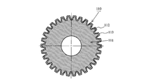
- a gear 110 as shown in FIG. 8 has been devised.
- the core material 111 is formed of a synthetic resin material including reinforcing fibers
- the tooth profile 112 of the core material 111 is a covering material 113 (a synthetic resin material not including reinforcing fibers, By covering with the same synthetic resin material), the tooth profile 112 of the core material 111 and the covering material 113 formed of the same synthetic resin material are firmly bonded.
- the gear 110 shown in FIG. 8 the gear 110 shown in FIG.
- the manufacturing cost can reduce the manufacturing cost by the amount that the mechanical fixing means need not be provided at the boundary portion between the tooth profile 112 and the covering material 113 as compared with the gear 100 of the first conventional example.
- the manufacturing cost can be reduced by the amount that the tooth profile 112 and the covering material 113 need not be fixed with an adhesive.
- 8 is similar to the gear 100 according to the first conventional example, the core material 111 is injection molded in the primary molding die, and the primary molding core material 111 is injected into the secondary molding die. Then, the molten covering material 113 is injected into the secondary molding die, and the tooth profile 112 of the core material 111 is coated with the covering material 113 (two-color molding). (See Patent Document 2).
- JP-A-1-250668 (especially, see the description in the upper right column on page 2) JP 2001-304379 A (refer to the description of paragraphs 0017, 0025 to 0035 in particular)
- the gear 110 according to the second conventional example has a problem that the covering material 113 is limited to the same material as the synthetic resin material of the core material 111.
- the present invention is to form a secondary molded body by coating the surface of a fiber reinforced synthetic resin body (primary molded body formed of a synthetic resin material containing reinforcing fibers) with a synthetic resin material not containing reinforcing fibers.
- An object of the present invention is to provide a two-color molding method in which the synthetic resin material is not limited to the same type and does not cause an increase in manufacturing cost, and a two-color molded body formed by this two-color molding method. To do.
- the present invention injects a synthetic resin material 2 a containing a reinforcing fiber in a molten state into a primary molding cavity 12 of a primary molding die 11, and a synthetic resin material 2 a containing a reinforcing fiber.
- the secondary molding cavity 31 does not contain a molten reinforcing fiber.
- the present invention relates to a two-color molding method in which a resin material (covering material 13) is injected, and the surface of the primary molded body 2 is coated with a synthetic resin material (covering material 13) that does not contain reinforcing fibers and the secondary molded body 1 is molded. It is.
- the synthetic resin material 2a containing the reinforcing fiber in a molten state is injected into the primary molding cavity 12, the primary molding cavity 12 is directed from one end side to the other end side.
- the synthetic resin material 2a including the reinforced fiber in the molten state is caused to flow, and a short shot is performed so that the other end side of the primary molding cavity 12 is not filled with the synthetic resin material 2a including the reinforced fiber in the molten state. .
- the reinforcing fiber 26 is exposed in a portion of the primary molded body 2 located on the other end side of the primary molding cavity 12, and the reinforcing fiber 26 is exposed in the exposed portion.
- a synthetic resin material (covering material 13) that does not contain the reinforcing fibers is coated. *
- the primary molded body core material
- a short shot of the synthetic resin material containing the reinforcing fiber in the molten state is performed on the other end side of the primary molded cavity of the primary molded body.
- the reinforcing fiber is exposed at the position where it is located, and the exposed reinforcing fiber functions as an anchor to increase the bonding strength between the covering material (synthetic resin material not including the reinforcing fiber) and the portion where the reinforcing fiber of the primary molded body is exposed. Therefore, there is no need to apply an adhesive to the joint between the primary molded body and the covering material, or there is no need to provide mechanical joining means such as irregularities at the joint between the primary molded body and the covering material.
- the manufacturing cost of the two-color molded body (synthetic resin gear) does not increase.
- the synthetic resin material in a molten state is short-shot to be positioned on the other end side of the primary molded cavity of the primary molded body. It is possible to expose the reinforcing fiber in the part, and to function the exposed reinforcing fiber as an anchor to increase the bonding strength between the covering material (synthetic resin material not including the reinforcing fiber) and the part where the reinforcing fiber of the primary molded body is exposed. Therefore, the synthetic resin material including the reinforcing fiber and the covering material are not limited to the same type of material.
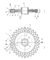
- FIG. 1A is a front view showing a primary molded body of a synthetic resin gear
- FIG. 1B is a cross-sectional view of the primary molded body cut along the line A1-A1 of FIG. 1A.
- FIG. 2 (a) is a front view showing a synthetic resin gear as a secondary molded body (two-color molded body)
- FIG. 2 (b) is cut along line A2-A2 in FIG. 2 (a).
- FIG. 1A is a front view showing a primary molded body of a synthetic resin gear
- FIG. 1B is a cross-sectional view of the primary molded body cut along the line A1-A1 of FIG. 1A.
- FIG. 2 (a) is a front view showing a synthetic resin gear as a secondary molded body
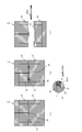
- FIG. 5A is a diagram showing a state in which a synthetic resin material containing reinforcing fibers is short-shot in the primary molding cavity, and is a partially enlarged view of a portion forming the teeth of the primary molding cavity.
- FIG. 5B is a diagram showing a state in which the primary molded body is accommodated in the secondary molding cavity, and is a partially enlarged view of a portion that forms the teeth of the secondary molding cavity.
- FIG.5 (c) is a figure which shows the state by which the synthetic resin material (coating material) which does not contain a reinforced fiber in the secondary molding cavity was injection-molded, and partially expanded the part which forms the tooth
- FIGS. 1 and 2 are views for explaining a synthetic resin gear 1 as a two-color molded body according to the first embodiment of the present invention.
- 1A is a front view showing a primary molded body 2 of the synthetic resin gear 1
- FIG. 1B is a primary molded product cut along the line A1-A1 of FIG. 1A.
- 3 is a cross-sectional view of the body 2.
- FIG. FIG. 2 (a) is a front view showing a synthetic resin gear 1 as a secondary molded body (two-color molded body), and
- FIG. 2 (b) is taken along line A2-A2 of FIG. 2 (a).
- 1 is a cross-sectional view of a synthetic resin gear 1 cut and shown.
- a primary molded body (core material) 2 includes a hollow disk-shaped web 4 in which a hole 3 is formed at the center, and a tooth portion 5 that is integrally formed at the radially outer end of the web 4; have.
- the tooth portion 5 includes a rim 6 formed in a ring shape along the outer peripheral edge of the web 4 and a plurality of teeth 7 formed along the outer periphery of the rim 6.
- the rim 6 is formed with a bottomed round hole-shaped recess (positioning engagement portion) 8 so as to correspond to the teeth 7 on a one-to-one basis and to be positioned in the vicinity of the teeth 7.
- a primary molded body 2 is made of a synthetic resin material (for example, nylon, PPS resin) 2 a including a reinforcing fiber (for example, glass fiber or carbon fiber) in a molten state, as a primary molding die 11. It is formed by being injected into the primary molding cavity 12 so as to form a short shot, and becomes a core material of the synthetic resin gear 1 as a secondary molded body.
- a synthetic resin material for example, nylon, PPS resin
- a reinforcing fiber for example, glass fiber or carbon fiber
- the short shot in the present invention is the amount of injection into the cavity so that the ratio of the portion where the cavity shape is accurately transferred and the portion where the reinforcing fiber described later is exposed becomes a desired ratio at the time of injection molding. Is intentionally controlled and systematically forms a primary molded body having an incomplete shape.
- the synthetic resin gear 1 as the secondary molded body shown in FIG. 2 is coated with a synthetic resin material (for example, nylon, POM) 13 that does not include reinforcing fibers in the portion of the primary molded body (core material) 2 except for the recesses 8.
- a synthetic resin material for example, nylon, POM
- a cylindrical boss 14 positioned at the radially inner end, a disk-shaped web 15 extending radially outward from the axial center of the outer peripheral surface of the boss 14, and the web 15 And a tooth portion 16 formed at the radially outer end.
- the tooth portion 16 of the synthetic resin gear 1 has a ring-shaped rim 17 connected to the radially outer end of the web 15 and a plurality of teeth 18 formed along the outer periphery of the rim 17. is doing.
- the synthetic resin gear 1 includes a synthetic resin material in which a cylindrical boss 14 does not contain reinforcing fibers (hereinafter referred to as a boss 14) at a position radially inward of the hole 3 formed in the center of the primary molded body 2. (Abbreviated as covering material) 13 only.
- a synthetic resin gear 1 the cross-sectional shape shown in FIG. 2B is symmetric with respect to the virtual line 20 that is located at the center of the tooth width direction of the tooth 18 and is orthogonal to the axis 21. It has a shape. And the meshing stress at the time of power transmission acts repeatedly on the teeth 18 of such a synthetic resin gear 1.
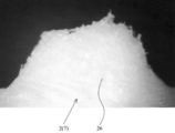
- the molten covering material 13 penetrates between the reinforcing fibers 26 exposed on the surfaces of the teeth 7 of the primary molded body 2 during injection molding (see FIG. 6). ), Since the exposed reinforcing fiber 26 functions as an anchor, and the bonding strength between the primary molded body 2 and the covering material 13 is enhanced by the anchor effect of the exposed reinforcing fiber 26, the primary molded body 2 and the covering material 13 Even if the meshing stress acts repeatedly on the interface, the covering material 13 is difficult to peel from the primary molded body 2, and the destruction of the teeth 18 due to the peeling of the interface between the primary molded body 2 and the covering material 13 is prevented.
- (2-color molding method) 3 to 4 are views for explaining a two-color molding method according to the first embodiment of the present invention.
- FIG. 3 is a view for explaining an injection molding process of the primary molded body 2.
- FIG. 4 is a view for explaining an injection molding process of the synthetic resin gear 1 as a secondary molded body.
- the fixed mold 22 and the movable mold 23 of the primary molding die 11 are clamped, and the primary part of the substantially hollow disc shape is formed at the abutting portion between the fixed mold 22 and the movable mold 23.
- a molding cavity 12 (primary molding cavity 12 for forming the primary molded body 2) is formed.
- the primary molding cavity 12 is in a molten state from a disk gate 24 formed in the fixed mold 22 so as to open to the radially inner end of the primary molding cavity 12.
- a synthetic resin material 2a containing reinforcing fibers is injected.
- the synthetic resin material 2 a including the molten reinforcing fiber injected into the primary molding cavity 12 is formed from the radially inner end side (one end side) of the primary molding cavity 12 to the radially outer end side of the primary molding cavity 12. It flows in the primary molding cavity 12 toward (the other end side).
- the synthetic resin material 2a containing molten reinforcing fibers is short shot so as not to fill the radially outer end of the primary molding cavity 12 in the injection process into the primary molding cavity 12 (FIG. 3 ( d)).
- the recess 8 of the primary molded body 2 is not affected by a short shot, and is formed at a position where the shape of the primary molding cavity 12 is transferred with high accuracy (see FIG. 1).
- the fixed mold 22 is provided with a ring gate (not shown) in place of the disk gate 24, and the synthetic resin material 2a including the molten reinforcing fiber is disposed on the radially inner end side of the primary molding cavity 12 from the ring gate. It may be ejected.
- FIG. 5A is an enlarged view of a portion 25 (portion located on the other end side) that forms the teeth of the primary molding cavity 12.
- the synthetic resin material 2 a containing the reinforcing fiber in the molten state is short shot into the primary molded cavity 12.
- the teeth 7 of the primary molding cavity 12 are slightly smaller than the portions 25 forming the teeth of the primary molding cavity 12, and a slight gap is formed between the teeth 7 of the primary molding body 2 and the portions 25 of the primary molding cavity 12 forming the teeth. Is formed.
- the reinforcing fibers 26 are exposed on the surfaces of the teeth 7 of the primary molded body 2 (see FIG. 6).
- the degree of exposure of the reinforcing fibers 26 in the primary molded body 2 increases as it goes from the tooth root side to the tooth tip side of the teeth 7 of the primary molded body 2.
- the shape of the primary molding cavity 12 is accurately transferred at a portion where the reinforcing fiber 26 is not exposed.
- the secondary molding die 27 is opened (the movable die 28 of the secondary molding die 27 is separated from the fixed die 30), and the secondary on the movable die 28 side.
- the primary molded body 2 is accommodated in a portion (movable mold side cavity portion 31a) constituting the molding cavity 31 (secondary molding cavity 31 for forming the synthetic resin gear 1 as a secondary molded body).
- the primary molded body 2 is concavo-convexly engaged with a round rod-shaped primary molded body positioning projection (primary molded body positioning means) 32 provided with the recess 8 in the movable mold cavity portion 31a, and the movable cavity portion 31a is engaged with the concave portion 8a. It is supported in a positioned state (see FIG. 4E).
- the fixed mold 30 and the movable mold 28 of the secondary molding die 27 are clamped, and the secondary molding cavity 31 is formed at the abutting portion between the fixed mold 30 and the movable mold 28.
- the primary molded body 2 is supported in a state in which the recess 8 on one side surface is engaged with the primary molded body positioning protrusion 32 of the movable mold 28 so as to be positioned in the movable cavity portion 31a, while the other
- the concave portion 8 on the side surface of the fixed plate 30 is engaged with the positioning projection 33 of the round rod-shaped primary molded body of the fixed mold 30 so that the fixed mold cavity portion 31b (the cavity portion on the fixed mold 30 side that constitutes the cavity 31 together with the movable mold cavity portion 31a). ) Is positioned (see FIG. 4F).
- FIG. 5B is an enlarged view of the portion 34 that forms the teeth of the secondary molding cavity 31.
- the primary molded body 2 when the primary molded body 2 is accommodated in a state of being positioned in the secondary molding cavity 31, the primary molded body 2 and the inner surface of the secondary molding cavity 31 are interposed. A gap for filling the molten coating material 13 is formed (see FIGS. 4B and 4F).
- the fixed die 30 is provided with a plurality of pin gates 36 that open to the portion 35 forming the web of the secondary molding cavity 31 at equal intervals around the central axis 37 of the secondary molding cavity 31.
- the molten coating material 13 is injected from the pin gate 36 into the secondary molding cavity 31.
- the coating material 13 is fully filled in the secondary molding cavity 31 (without being short shot, the gap is formed in the secondary molding cavity 31. Without filling).
- the molten covering material 13 injected into the secondary molding cavity 31 penetrates into the minute gaps between the reinforcing fibers 26 exposed from the primary molded body 2 (see FIG. 6), and the surface of the primary molded body 2 It is strongly fixed to.
- a primary molded body positioning protrusion in which a recess 8 located near the tooth 7 of the primary molded body 2 is provided in the secondary molding cavity 31 (
- the primary molded body positioning means) 32 and 33 are engaged with the projections and depressions, and are supported in a state where the vicinity of the teeth 7 of the primary molded body 2 is positioned by the primary molded body positioning projections 32 and 33 provided in the secondary molding cavity 31. Therefore, the primary molded body 2 does not move in the secondary molding cavity 31, and the covering material 13 is accurately coated on the primary molded body 2 with a predetermined film thickness. As a result, the exposed reinforcing fiber 26 of the primary molded body 2 is not exposed to the outside of the covering material 13 and is not directly in contact with the mating gear.
- the coating material 13 injected into the secondary molding cavity 31 is cooled and solidified, and the synthetic resin gear 1 as the secondary molded body is secondary molded.
- the movable mold 28 of the secondary molding die 27 is separated from the fixed mold 30 (mold separation), and the synthetic resin gear 1 in the secondary molding cavity 31 is installed in the movable mold 28.
- the synthetic resin gear 1 is pushed out from the secondary molding die 27 by being pushed out by an unillustrated extrusion pin. Thereby, the injection molding process of the two-color molded body (synthetic resin gear 1) is completed.
- the reinforcing fibers 26 are exposed to the teeth 7 of the primary molded body 2 by performing a short shot when the primary molded body (core material) 2 is injection molded. Since the exposed reinforcing fiber 26 functions as an anchor, and the bonding strength between the covering material 13 and the tooth 7 of the primary molded body 2 can be increased by the anchor effect of the exposed reinforcing fiber 26, the tooth 7 of the primary molded body 2 can be increased. It is not necessary to apply an adhesive between the coating material 13 and the covering material 13, or it is not necessary to provide mechanical joining means such as irregularities at the joint between the teeth 7 of the primary molded body 2 and the covering material 13, and the synthetic resin. The manufacturing cost of the gear manufacturing (two-color molded body) 1 is not increased.
- the reinforcing fiber 26 is exposed to the teeth 7 of the primary molded body 2 by performing a short shot when the primary molded body (core material) 2 is injection molded. Since the exposed reinforcing fiber 26 functions as an anchor, and the bonding strength between the covering material 13 and the teeth 7 of the primary molded body 2 can be increased by the anchor effect of the exposed reinforcing fiber 26, the synthetic resin material 2a containing the reinforcing fiber,
- the covering material 13 is not limited to the same type of material.
- the synthetic resin material 2a including the reinforcing fibers forming the primary molded body 2 and the material of the covering material 13 are not limited to the same type of material. It is of course possible to form a high-strength and high-precision synthetic resin gear (two-color molded body) 1 by appropriately selecting the material of the synthetic resin material 2a including the reinforcing fibers forming the primary molded body 2 and the covering material 13. In other words, a synthetic resin gear (two-color molded body) 1 can be manufactured in accordance with required characteristics (slidability, wear resistance, quietness, etc.).
- the synthetic resin gear (two-color molded body) 1 molded by the two-color molding method according to the present embodiment is a material softer than the synthetic resin material 2a in which the covering material 13 includes the reinforcing fibers of the primary molded body 2.
- the film thickness of the covering material 13 becomes thicker from the tooth base side of the tooth 18 of the synthetic resin gear (two-color molded body) 1 toward the tooth tip side, and goes from the tooth base side of the tooth 18 to the tooth tip side. Accordingly, since the softness of the surface of the tooth 18 increases, when used on the driven side, it is possible to further reduce the operation noise (meshing noise with the counterpart gear).
- the teeth 7 of the primary molded body (core material) 2 and the covering material 13 are strongly fixed by the anchor effect of the reinforcing fibers 26 exposed in the primary molded body 2. Further, it is possible to prevent the teeth 18 of the synthetic resin gear (two-color molded body) 1 from being broken due to the peeling of the interface between the primary molded body 2 and the covering material 13.
- the recesses 8 of the primary molded body 2 are provided on a one-to-one basis with the teeth 7, and the primary molded body 7 is a secondary molding cavity.
- the primary molded body positioning protrusions 32 and 33 formed on the secondary molding cavity 31 side are engaged with the recess 8 of the primary molded body 7, and the secondary molding cavity 31 is in a molten state.
- the primary molded body positioning protrusions 32 and 33 adjust the flow of the molten coating material 13, and the molten coating material 13 is applied to the portion 34 forming each tooth of the secondary molding cavity 31. Since it can be made to flow evenly, the shape of the tooth 18 can be formed with high accuracy.
- the number of the dents 8 in the primary molded body 2 is determined according to the required gear accuracy, injection conditions, and the like, and may be smaller than the number of teeth 7.
- the synthetic resin gear 1 is illustrated as a two-color molded body.
- rotation transmission means such as a sprocket, a toothed belt pulley, and a roller are also two-color molded.
- the sprocket is short-shot during the injection molding of the primary molded body (core material) to expose the reinforcing fibers on the surface of the teeth located on the radially outer end side of the primary molded body, and the teeth where the reinforcing fibers are exposed.
- a coating material is coated on the surface.
- the pulley for the toothed belt is short shot at the time of injection molding of the primary molded body to expose the reinforcing fiber on the surface of the tooth located on the radially outer end side of the primary molded body, and this reinforcing fiber is exposed. Cover the teeth with a dressing. Further, the roller is short shot at the time of injection molding of the primary molded body (core material) to expose the reinforcing fiber on the surface of the cylindrical portion located on the radially outer end side of the primary molded body, and this reinforcing fiber is exposed. Cover the cylindrical portion with a covering material.
- Such a rotation transmission means is formed by applying a two-color molding method for molding the synthetic resin gear 1 according to the embodiment.
- the primary molded body 2 has the recess 8 as the positioning engagement portion, but a round bar-like protrusion may be used as the positioning engagement portion.
- a recess that engages with the round bar-like protrusion of the primary molded body 2 may be used as the primary molded body positioning means.
- SYMBOLS 1 Secondary molded object (two-color molded object, synthetic resin gear), 2 ... Primary molded object (core material), 2a ... Synthetic resin material including reinforcing fiber, 11 ... Primary molding die, 12 ... ... primary molding cavity, 13 ... coating material (synthetic resin material not containing reinforcing fibers), 26 ... reinforcing fiber, 27 ... secondary molding die, 31 ... secondary molding cavity
Landscapes
- Engineering & Computer Science (AREA)
- Mechanical Engineering (AREA)
- General Engineering & Computer Science (AREA)
- Manufacturing & Machinery (AREA)
- Physics & Mathematics (AREA)
- Electromagnetism (AREA)
- Thermal Sciences (AREA)
- Injection Moulding Of Plastics Or The Like (AREA)
- Gears, Cams (AREA)
- Moulding By Coating Moulds (AREA)
Abstract
【課題】強化繊維を含む合成樹脂材料で形成された一次成形体の表面に、強化繊維を含まない合成樹脂材料を被覆して二次成形体を形作るに際し、合成樹脂材料が同一種に限定されることがなく、且つ、製造コストの高騰を招くことがない2色成形方法を提供する。 【解決手段】一次成形キャビティ12内に溶融状態の強化繊維を含む合成樹脂材料2aを射出して一次成形体2を形成する際に、一次成形キャビティ12の一端側から他端側へ向けて溶融状態の強化繊維を含む合成樹脂材料2aを流動させると共に、ショートショットさせる。これにより、一次成形体2のうちの一次成形キャビティ12の他端側に位置する歯7に強化繊維を露出させる。そして、二次成形キャビティ内において、この強化繊維が露出した歯7に強化繊維を含まない合成樹脂材料(被覆材)13が被覆され、2色成形体としての合成樹脂製歯車1が形作られる。
Description
この発明は、一次成形体としての繊維強化合成樹脂体の表面に、強化繊維を含まない合成樹脂材料を被覆して二次成形体を形作る2色成形方法、及びこの2色成形方法によって形作られた2色成形体に関するものである。
近年、例えば、複写機や自動車の動力伝達部品としての歯車は、重量が軽く、機械的強度が高く、形状精度が高精度で、且つ動力伝達時の作動音が小さいものが使用される。
(第1従来例)
図7は、このような従来の歯車100を示す図である。この図7に示す歯車100は、本体部101が硬質合成樹脂材料で形成され、歯形部102が軟質合成樹脂材料で形成されており、硬質合成樹脂材料で形成された本体部101で所定の機械的強度を得るようにし、軟質合成樹脂材料で形成された歯形部102で動力伝達時(噛み合い時)の作動音を小さくするようになっている。そして、この従来の歯車100は、本体部101を一次成形金型内で射出成形し、この一次成形された本体部101を二次成形金型内に収容した後、軟質合成樹脂材料を二次成形金型内に射出し、本体部101の外周側に歯形部102を一体に成形する(2色成形する)ようになっている(特許文献1参照)。
図7は、このような従来の歯車100を示す図である。この図7に示す歯車100は、本体部101が硬質合成樹脂材料で形成され、歯形部102が軟質合成樹脂材料で形成されており、硬質合成樹脂材料で形成された本体部101で所定の機械的強度を得るようにし、軟質合成樹脂材料で形成された歯形部102で動力伝達時(噛み合い時)の作動音を小さくするようになっている。そして、この従来の歯車100は、本体部101を一次成形金型内で射出成形し、この一次成形された本体部101を二次成形金型内に収容した後、軟質合成樹脂材料を二次成形金型内に射出し、本体部101の外周側に歯形部102を一体に成形する(2色成形する)ようになっている(特許文献1参照)。
しかしながら、図7に示す従来の歯車100は、本体部101と歯形部102とが異なる材料で形成されるため、本体部101と歯形部102の境界部分における結合状態が不安定になる虞があり、本体部101と歯形部102との境界部分に凹凸等の機械的固定手段103を設けるか、又は、本体部101と歯形部102とを接着剤で固定するようになっている。そのため、図7に示す従来の歯車100は、金型構造が複雑化するか、又は接着剤塗布工程を別途設ける必要があり、製造コストが高くなるという問題を有していた。
(第2従来例)
このような問題を解決するものとして、図8に示すような歯車110が案出された。この図8に示す歯車110は、心材111が強化繊維を含む合成樹脂材料で形成され、心材111の歯形部112が被覆材113(強化繊維を含まない合成樹脂材料であって、心材111の合成樹脂材料と同一の合成樹脂材料)で被覆されることにより、同一の合成樹脂材料で形成された心材111の歯形部112と被覆材113とが強固に結合されるようになっている。その結果、図8に示す歯車110は、第1従来例の歯車100と比較し、機械的固定手段を歯形部112と被覆材113の境界部分に設ける必要がなくなった分だけ製造コストを低減できるか、又は、歯形部112と被覆材113を接着剤で固定する必要がなくなった分だけ製造コストを低減することができる。そして、この図8に示す歯車110は、第1従来例に係る歯車100と同様に、心材111を一次成形金型内で射出成形し、この一次成形された心材111を二次成形金型内に収容した後、溶融状態の被覆材113を二次成形金型内に射出し、心材111の歯形部112に被覆材113を被覆することによって形成される(2色成形される)ようになっている(特許文献2参照)。
このような問題を解決するものとして、図8に示すような歯車110が案出された。この図8に示す歯車110は、心材111が強化繊維を含む合成樹脂材料で形成され、心材111の歯形部112が被覆材113(強化繊維を含まない合成樹脂材料であって、心材111の合成樹脂材料と同一の合成樹脂材料)で被覆されることにより、同一の合成樹脂材料で形成された心材111の歯形部112と被覆材113とが強固に結合されるようになっている。その結果、図8に示す歯車110は、第1従来例の歯車100と比較し、機械的固定手段を歯形部112と被覆材113の境界部分に設ける必要がなくなった分だけ製造コストを低減できるか、又は、歯形部112と被覆材113を接着剤で固定する必要がなくなった分だけ製造コストを低減することができる。そして、この図8に示す歯車110は、第1従来例に係る歯車100と同様に、心材111を一次成形金型内で射出成形し、この一次成形された心材111を二次成形金型内に収容した後、溶融状態の被覆材113を二次成形金型内に射出し、心材111の歯形部112に被覆材113を被覆することによって形成される(2色成形される)ようになっている(特許文献2参照)。
しかしながら、第2従来例に係る歯車110は、被覆材113が心材111の合成樹脂材料と同一の材料に限定されるという不具合を有していた。
そこで、本発明は、繊維強化合成樹脂体(強化繊維を含む合成樹脂材料で形成された一次成形体)の表面に、強化繊維を含まない合成樹脂材料を被覆して二次成形体を形作るに際し、合成樹脂材料が同一種に限定されることがなく、且つ、製造コストの高騰を招くことがない2色成形方法、及びこの2色成形方法によって形作られた2色成形体の提供を目的とする。
図1乃至図6に示すように、本発明は、一次成形金型11の一次成形キャビティ12内に溶融状態の強化繊維を含む合成樹脂材料2aを射出して、強化繊維を含む合成樹脂材料2aからなる一次成形体2を形作り、この一次成形体2を二次成形金型27の二次成形キャビティ31内に収容した後、前記二次成形キャビティ31内に溶融状態の強化繊維を含まない合成樹脂材料(被覆材13)を射出し、前記一次成形体2の表面に強化繊維を含まない合成樹脂材料(被覆材13)を被覆して二次成形体1を成形する2色成形方法に関するものである。この発明に係る2色成形方法は、前記一次成形キャビティ12内に溶融状態の前記強化繊維を含む合成樹脂材料2aを射出する際に、前記一次成形キャビティ12の一端側から他端側へ向けて溶融状態の前記強化繊維を含む合成樹脂材料2aを流動させると共に、前記一次成形キャビティ12の前記他端側が溶融状態の前記強化繊維を含む合成樹脂材料2aで満たされることがないようにショートショットさせる。そして、この発明に係る2色成形方法は、前記一次成形体2のうち、前記一次成形キャビティ12の他端側に位置する部分に強化繊維26を露出させ、この強化繊維26が露出した部分に前記強化繊維を含まない合成樹脂材料(被覆材13)が被覆されるようになっている。
本発明によれば、一次成形体(心材)を射出成形する際に、溶融状態の強化繊維を含む合成樹脂材料をショートショットさせることにより、一次成形体のうちの一次成形キャビティの他端側に位置する部分に強化繊維を露出させ、この露出した強化繊維をアンカーとして機能させ、被覆材(強化繊維を含まない合成樹脂材料)と一次成形体の強化繊維が露出した部分との接合強度を上げることができるため、一次成形体と被覆材との接合部に接着剤を塗布する必要がないか、又は一次成形体と被覆材との接合部に凹凸等の機械的接合手段を設ける必要がなく、2色成形体(合成樹脂製歯車)の製造コストの高騰を招くことがない。
また、本発明によれば、一次成形体(心材)を射出成形する際に、溶融状態の合成樹脂材料をショートショットさせることにより、一次成形体のうちの一次成形キャビティの他端側に位置する部分に強化繊維を露出させ、この露出した強化繊維をアンカーとして機能させ、被覆材(強化繊維を含まない合成樹脂材料)と一次成形体の強化繊維が露出した部分との接合強度を上げることができるため、強化繊維を含む合成樹脂材料と被覆材とが同一種の材料に限定されることがない。
以下、本発明の実施形態を図面に基づき詳述する。
(2色成形体)
図1乃至図2は、本発明の第1実施形態に係る2色成形体としての合成樹脂製歯車1を説明するための図である。なお、図1(a)は合成樹脂製歯車1の一次成形体2を示す正面図であり、図1(b)は図1(a)のA1-A1線に沿って切断して示す一次成形体2の断面図である。また、図2(a)は二次成形体(2色成形体)としての合成樹脂製歯車1を示す正面図であり、図2(b)は図2(a)のA2-A2線に沿って切断して示す合成樹脂製歯車1の断面図である。
図1乃至図2は、本発明の第1実施形態に係る2色成形体としての合成樹脂製歯車1を説明するための図である。なお、図1(a)は合成樹脂製歯車1の一次成形体2を示す正面図であり、図1(b)は図1(a)のA1-A1線に沿って切断して示す一次成形体2の断面図である。また、図2(a)は二次成形体(2色成形体)としての合成樹脂製歯車1を示す正面図であり、図2(b)は図2(a)のA2-A2線に沿って切断して示す合成樹脂製歯車1の断面図である。
図1において、一次成形体(心材)2は、中心に穴3が形成された中空円板状のウェブ4と、このウェブ4の径方向外方端に一体に形成された歯部5と、を有している。また、歯部5は、ウェブ4の外周端に沿ってリング状に形成されたリム6と、このリム6の外周に沿って複数形成された歯7と、を有している。また、リム6には、有底の丸穴状の凹み(位置決め係合部)8が歯7と一対一で対応し且つ歯7の近傍に位置するように形成されている。そして、凹み8は、その中心が歯7の歯厚中心線10上に位置し、リム6の両側面に形成されている。このような一次成形体2は、図3に示すように、溶融状態の強化繊維(例えば、ガラス繊維、炭素繊維)を含む合成樹脂材料(例えば、ナイロン、PPS樹脂)2aを一次成形金型11の一次成形キャビティ12内にショートショットとなるように射出することにより形成され、二次成形体としての合成樹脂製歯車1の心材になる。なお、本発明におけるショートショットは、射出成形時において、キャビティ形状が正確に転写される部分と後述する強化繊維を露出させる部分との割合が所望の割合になるように、キャビティ内への射出量を意図的に制御し、不完全な形状の一次成形体を計画的に形作ることをいう。
図2に示す二次成形体としての合成樹脂製歯車1は、一次成形体(心材)2の凹み8を除く部分が強化繊維を含まない合成樹脂材料(例えば、ナイロン、POM)13で被覆されており、径方向内方端に位置する円筒状のボス14と、このボス14の外周面の軸方向中央部から径方向外方へ向かって延びる円板状のウェブ15と、このウェブ15の径方向外方端に形成された歯部16と、を有している。また、この合成樹脂製歯車1の歯部16は、ウェブ15の径方向外方端に接続されるリング状のリム17と、このリム17の外周に沿って複数形成された歯18とを有している。また、この合成樹脂製歯車1は、一次成形体2の中心に形成された穴3よりも径方向内方側の位置に、円筒状のボス14が強化繊維を含まない合成樹脂材料(以下、被覆材と略称する)13のみで形作られている。また、合成樹脂製歯車1は、図2(b)に示す断面形状が、歯18の歯幅方向中央に位置する仮想線20で且つ軸心21に直交する仮想線20に対し、線対称の形状になっている。そして、このような合成樹脂製歯車1の歯18には、動力伝達時の噛み合い応力が繰り返し作用する。しかし、合成樹脂製歯車1は、後述するように、射出成形時において、一次成形体2の歯7の表面に露出した強化繊維26の間に溶融状態の被覆材13が浸透し(図6参照)、露出した強化繊維26がアンカーとして機能して、一次成形体2と被覆材13との接合強度が露出した強化繊維26のアンカー効果によって高められるため、一次成形体2と被覆材13との界面に噛み合い応力が繰り返し作用しても、被覆材13が一次成形体2から剥離し難くなり、一次成形体2と被覆材13との界面の剥離に起因する歯18の破壊が防止される。
(2色成形方法)
図3乃至図4は、本発明の第1実施形態に係る2色成形方法を説明するための図である。なお、図3は、一次成形体2の射出成形工程を説明する図である。また、図4は、二次成形体としての合成樹脂製歯車1の射出成形工程を説明する図である。
図3乃至図4は、本発明の第1実施形態に係る2色成形方法を説明するための図である。なお、図3は、一次成形体2の射出成形工程を説明する図である。また、図4は、二次成形体としての合成樹脂製歯車1の射出成形工程を説明する図である。
まず、図3(a)に示すように、一次成形金型11の固定型22と可動型23を型締めして、固定型22と可動型23との突き合わせ部に略中空円板状の一次成形キャビティ12(一次成形体2を形作るための一次成形キャビティ12)を形成する。
次に、図3(b)に示すように、一次成形キャビティ12には、この一次成形キャビティ12の径方向内方端に開口するように固定型22に形成されたディスクゲート24から溶融状態の強化繊維を含む合成樹脂材料2aが射出される。この一次成形キャビティ12内に射出された溶融状態の強化繊維を含む合成樹脂材料2aは、一次成形キャビティ12の径方向内方端側(一端側)から一次成形キャビティ12の径方向外方端側(他端側)へ向けて一次成形キャビティ12内を流動する。そして、溶融状態の強化繊維を含む合成樹脂材料2aは、一次成形キャビティ12への射出工程において、一次成形キャビティ12の径方向外方端を満たすことがないようにショートショットされる(図3(d)参照)。そして、一次成形体2の凹み8は、ショートショットの影響がなく、一次成形キャビティ12の形状が高精度で転写される位置に形成されるようになっている(図1参照)。なお、固定型22は、ディスクゲート24に代えてリングゲート(図示せず)を設け、溶融状態の強化繊維を含む合成樹脂材料2aがリングゲートから一次成形キャビティ12の径方向内方端側に射出されるものでもよい。
次に、図3(c)に示すように、一次成形キャビティ12内に射出された強化繊維を含む合成樹脂材料2aが冷えて固まり、一次成形キャビティ12内で一次成形体2が形作られると、一次成形金型11の可動型23を固定型22から分離し(型分離し)、一次成形キャビティ12内の一次成形体2が可動型23に設置された図示しない押し出しピンによって押し出され、一次成形体2が一次成形金型11から取り出される。
図5(a)は、一次成形キャビティ12の歯を形成する部分25(他端側に位置する部分)を拡大した図である。この図5(a)に示すように、一次成形体2の射出成形工程において、溶融状態の強化繊維を含む合成樹脂材料2aが一次成形キャビティ12内にショートショットされることにより、一次成形体2の歯7が一次成形キャビティ12の歯を形成する部分25よりも僅かに小さく形成され、一次成形体2の歯7と一次成形キャビティ12の歯を形成する部分25との間には僅かな隙間が形成される。そして、一次成形体2の歯7の表面には、強化繊維26が露出する(図6参照)。この一次成形体2における強化繊維26の露出の程度は、一次成形体2の歯7の歯元側から歯先側へ向かうに従って大きくなっている。一方、この一次成形体2において、強化繊維26が露出していない部分は、一次成形キャビティ12の形状が精度良く転写されている。
次に、図4(a)に示すように、二次成形金型27を型開きし(二次成形金型27の可動型28を固定型30から分離し)、可動型28側の二次成形キャビティ31(二次成形体としての合成樹脂製歯車1を形作るための二次成形キャビティ31)を構成する部分(可動型側キャビティ部分31a)に一次成形体2を収容する。この際、一次成形体2は、凹み8が可動型キャビティ部分31aに設けられた丸棒状の一次成形体位置決め突起(一次成形体位置決め手段)32に凹凸係合させられ、可動型キャビティ部分31aに位置決めされた状態で支持されている(図4(e)参照)。
次に、図4(b)に示すように、二次成形金型27の固定型30と可動型28を型締めし、固定型30と可動型28との突き合わせ部に二次成形キャビティ31を形成する。この際、一次成形体2は、一方の側面側の凹み8が可動型28の一次成形体位置決め突起32に凹凸係合し、可動型キャビティ部分31aに位置決めされた状態で支持されると共に、他方の側面側の凹み8が固定型30の丸棒状の一次成形体位置決め突起33に凹凸係合し、固定型キャビティ部分31b(可動型キャビティ部分31aと共にキャビティ31を構成する固定型30側のキャビティ部分)に位置決めされた状態で支持される(図4(f)参照)。
図5(b)は、二次成形キャビティ31の歯を形成する部分34を拡大した図である。この図5(b)に示すように、一次成形体2が二次成形キャビティ31内に位置決めされた状態で収容されると、一次成形体2と二次成形キャビティ31の内面との間には、溶融状態の被覆材13を充填するための隙間が形成される(図4(b)、(f)参照)。なお、固定型30には、二次成形キャビティ31のウェブを形作る部分35に開口するピンゲート36が二次成形キャビティ31の中心軸37の周囲に等間隔で複数設けられている。
次に、図4(c)及び図5(c)に示すように、二次成形キャビティ31内には、溶融状態の被覆材13がピンゲート36から射出される。この二次成形体としての合成樹脂製歯車1の射出成形工程において、被覆材13は、二次成形キャビティ31内にフル充填される(ショートショットされることなく、二次成形キャビティ31内に隙間なく充填される)。そして、二次成形キャビティ31内に射出された溶融状態の被覆材13は、一次成形体2から露出する強化繊維26間の微小な隙間に浸透し(図6参照)、一次成形体2の表面に強く固定される。
この二次成形キャビティ31内に溶融状態の被覆材13が射出される際、一次成形体2の歯7の近傍に位置する凹み8が二次成形キャビティ31に設けられた一次成形体位置決め突起(一次成形体位置決め手段)32,33に凹凸係合させられ、一次成形体2の歯7の近傍が二次成形キャビティ31に設けられた一次成形体位置決め突起32,33で位置決めされた状態で支持されるため、一次成形体2が二次成形キャビティ31内でズレ動くようなことがなく、被覆材13が一次成形体2に所定の膜厚で正確に被覆される。その結果、一次成形体2の露出した強化繊維26は、被覆材13の外方へ露出するようなことがなく、噛み合う相手歯車に直接接触するようなことがない。
次に、図4(c),(d)に示すように、二次成形キャビティ31内に射出された被覆材13が冷えて固まり、二次成形体としての合成樹脂製歯車1が二次成形キャビティ31内で形作られると、二次成形金型27の可動型28を固定型30から分離し(型分離し)、二次成形キャビティ31内の合成樹脂製歯車1が可動型28に設置された図示しない押し出しピンによって押し出され、合成樹脂製歯車1が二次成形金型27から取り出される。これにより、2色成形体(合成樹脂製歯車1)の射出成形工程が終了する。
(本実施形態の効果)
以上のような本実施形態に係る2色成形方法によれば、一次成形体(心材)2を射出成形する際にショートショットさせることにより、一次成形体2の歯7に強化繊維26を露出させ、この露出した強化繊維26をアンカーとして機能させ、被覆材13と一次成形体2の歯7の接合強度を露出した強化繊維26のアンカー効果で上げることができるため、一次成形体2の歯7と被覆材13との間に接着剤を塗布する必要がないか、又は一次成形体2の歯7と被覆材13との接合部に凹凸等の機械的接合手段を設ける必要がなく、合成樹脂製歯車(2色成形体)1の製造コストの高騰を招くことがない。
以上のような本実施形態に係る2色成形方法によれば、一次成形体(心材)2を射出成形する際にショートショットさせることにより、一次成形体2の歯7に強化繊維26を露出させ、この露出した強化繊維26をアンカーとして機能させ、被覆材13と一次成形体2の歯7の接合強度を露出した強化繊維26のアンカー効果で上げることができるため、一次成形体2の歯7と被覆材13との間に接着剤を塗布する必要がないか、又は一次成形体2の歯7と被覆材13との接合部に凹凸等の機械的接合手段を設ける必要がなく、合成樹脂製歯車(2色成形体)1の製造コストの高騰を招くことがない。
また、本実施形態に係る2色成形方法によれば、一次成形体(心材)2を射出成形する際にショートショットさせることにより、一次成形体2の歯7に強化繊維26を露出させ、この露出した強化繊維26をアンカーとして機能させ、被覆材13と一次成形体2の歯7の接合強度を露出した強化繊維26のアンカー効果で上げることができるため、強化繊維を含む合成樹脂材料2aと被覆材13とが同一種の材料に限定されることがない。
また、本実施形態に係る2色成形方法によれば、上述のように、一次成形体2を形作る強化繊維を含む合成樹脂材料2aと被覆材13の材料が同一種の材料に限定されないため、一次成形体2を形作る強化繊維を含む合成樹脂材料2aと被覆材13の材料を適宜選択することにより、高強度で且つ高精度の合成樹脂製歯車(2色成形体)1を形成できることはもちろんのこと、要求される特性(摺動性、耐摩耗性、静音性等)に応じた合成樹脂製歯車(2色成形体)1を製造することができる。
また、本実施形態に係る2色成形方法によれば、一次成形体2における強化繊維26の露出の程度は、一次成形体2の歯7の歯元側から歯先側へ向かうに従って大きくなっている。したがって、本実施形態に係る2色成形方法によって成形された合成樹脂製歯車(2色成形体)1は、被覆材13が一次成形体2の強化繊維を含む合成樹脂材料2aよりも軟らかい材料である場合、被覆材13の膜厚が合成樹脂製歯車(2色成形体)1の歯18の歯元側から歯先側へ向かうに従って厚くなり、歯18の歯元側から歯先側へ向かうに従って歯18の表面の軟らかさが増すため、被動側で使用されると、作動音(相手歯車との噛み合い音)をより一層低減することができる。
又、本実施形態に係る2色成形方法によれば、一次成形体(心材)2の歯7と被覆材13とが一次成形体2の露出した強化繊維26のアンカー効果によって強く固定されるため、一次成形体2と被覆材13との界面の剥離に起因する合成樹脂製歯車(2色成形体)1の歯18の破壊を防止することができる。
また、本実施形態に係る2色成形方法によって形成される合成樹脂製歯車1は、一次成形体2の凹み8が歯7と一対一で設けられており、一次成形体7が二次成形キャビティ31に収容された際に、一次成形体7の凹み8に二次成形キャビティ31側に形成された一次成形体位置決め突起32,33が係合され、二次成形キャビティ31内に溶融状態の被覆材13が射出されると、各一次成形体位置決め突起32,33が溶融状態の被覆材13の流れを整え、溶融状態の被覆材13を二次成形キャビティ31の各歯を形成する部分34に均等に流動させることができるため、歯18の形状を高精度に成形することができる。なお、一次成形体2の凹み8の数は、求められる歯車精度や射出条件等に応じて決定され、歯7の数よりも少なくしてもよい。
(変形例)
上記本実施形態において、2色成形体としての合成樹脂製歯車1を例示したが、本発明は、これに限定されず、スプロケット、歯付きベルト用プーリ、ローラ等の回転伝達手段も2色成形体として適用することができる。なお、スプロケットは、一次成形体(心材)の射出成形時にショートショットさせて、一次成形体の径方向外方端側に位置する歯の表面に強化繊維を露出させ、この強化繊維が露出した歯に被覆材を被覆する。また、歯付きベルト用プーリは、一次成形体の射出成形時にショートショットさせて、一次成形体の径方向外方端側に位置する歯の表面に強化繊維を露出させ、この強化繊維が露出した歯に被覆材を被覆する。また、ローラは、一次成形体(心材)の射出成形時にショートショットさせて、一次成形体の径方向外方端側に位置する円筒部の表面に強化繊維を露出させ、この強化繊維が露出した円筒部に被覆材を被覆する。このような回転伝達手段は、上記実施形態に係る合成樹脂製歯車1を成形するための2色成形方法を適用して形成される。
上記本実施形態において、2色成形体としての合成樹脂製歯車1を例示したが、本発明は、これに限定されず、スプロケット、歯付きベルト用プーリ、ローラ等の回転伝達手段も2色成形体として適用することができる。なお、スプロケットは、一次成形体(心材)の射出成形時にショートショットさせて、一次成形体の径方向外方端側に位置する歯の表面に強化繊維を露出させ、この強化繊維が露出した歯に被覆材を被覆する。また、歯付きベルト用プーリは、一次成形体の射出成形時にショートショットさせて、一次成形体の径方向外方端側に位置する歯の表面に強化繊維を露出させ、この強化繊維が露出した歯に被覆材を被覆する。また、ローラは、一次成形体(心材)の射出成形時にショートショットさせて、一次成形体の径方向外方端側に位置する円筒部の表面に強化繊維を露出させ、この強化繊維が露出した円筒部に被覆材を被覆する。このような回転伝達手段は、上記実施形態に係る合成樹脂製歯車1を成形するための2色成形方法を適用して形成される。
また、上記実施形態において、一次成形体2は、位置決め係合部として凹み8を形成しているが、丸棒状の突起を位置決め係合部としてもよい。一方、二次成形キャビティ31は、一次成形体2の丸棒状の突起に凹凸係合する凹みを一次成形体位置決め手段としてもよい。
1……二次成形体(2色成形体、合成樹脂製歯車)、2……一次成形体(心材)、2a……強化繊維を含む合成樹脂材料、11……一次成形金型、12……一次成形キャビティ、13……被覆材(強化繊維を含まない合成樹脂材料)、26……強化繊維、27……二次成形金型、31……二次成形キャビティ
Claims (6)
- 一次成形金型の一次成形キャビティ内に溶融状態の強化繊維を含む合成樹脂材料を射出して、強化繊維を含む合成樹脂材料からなる一次成形体を形作り、この一次成形体を二次成形金型の二次成形キャビティ内に収容した後、前記二次成形キャビティ内に溶融状態の強化繊維を含まない合成樹脂材料を射出し、前記一次成形体の表面に前記強化繊維を含まない合成樹脂材料を被覆して二次成形体を成形する2色成形方法において、
前記一次成形キャビティ内に溶融状態の前記強化繊維を含む合成樹脂材料を射出する際に、前記一次成形キャビティの一端側から他端側へ向けて溶融状態の前記強化繊維を含む合成樹脂材料を流動させると共に、前記一次成形キャビティの前記他端側が溶融状態の前記強化繊維を含む合成樹脂材料で満たされることがないようにショートショットさせて、
前記一次成形体のうち、前記一次成形キャビティの他端側に位置する部分に強化繊維を露出させ、この強化繊維が露出した部分に前記強化繊維を含まない合成樹脂材料が被覆される、
ことを特徴とする2色成形方法。 - 一次成形金型の一次成形キャビティ内に溶融状態の強化繊維を含む合成樹脂材料を射出して、強化繊維を含む合成樹脂材料からなる一次成形体を形作り、この一次成形体を二次成形金型の二次成形キャビティ内に収容した後、前記二次成形キャビティ内に溶融状態の強化繊維を含まない合成樹脂材料を射出し、前記一次成形体の表面に強化繊維を含まない合成樹脂材料を被覆してなる2色成形体において、
前記一次成形キャビティ内に溶融状態の前記強化繊維を含む合成樹脂材料を射出する際に、前記一次成形キャビティの一端側から他端側へ向けて溶融状態の前記強化繊維を含む合成樹脂材料を流動させると共に、前記一次成形キャビティの前記他端側が溶融状態の前記強化繊維を含む合成樹脂材料で満たされることがないようにショートショットさせて、
前記一次成形体のうち、前記一次成形キャビティの他端側に位置する部分に強化繊維を露出させ、この強化繊維が露出した部分に前記強化繊維を含まない合成樹脂材料が被覆されてなる、
ことを特徴とする2色成形体。 - 前記一次成形体が歯車の一次成形体であり、
前記二次成形体が合成樹脂製歯車であり、
前記一次成形体のうち、前記一次成形キャビティの他端側に位置する前記歯車の歯を形作る部分に強化繊維を露出させ、この強化繊維が露出した前記歯を形作る部分に前記強化繊維を含まない合成樹脂材料が被覆される、
ことを特徴とする請求項1記載の2色成形方法。 - 前記一次成形体が歯車の一次成形体であり、
前記二次成形体が合成樹脂製歯車であり、
前記一次成形体のうち、前記一次成形キャビティの他端側に位置する前記歯車の歯を形作る部分に強化繊維を露出させ、この強化繊維が露出した前記歯を形作る部分に前記強化繊維を含まない合成樹脂材料が被覆されてなる、
ことを特徴とする請求項2記載の2色成形体。 - 前記一次成形体は、前記歯の近傍で且つ前記一次成形キャビティの形状が正確に転写される部分に、前記二次成形キャビティの一次成形体位置決め手段と凹凸係合する位置決め係合部が形成される、
ことを特徴とする請求項3記載の2色成形方法。 - 前記一次成形体は、前記歯の近傍で且つ前記一次成形キャビティの形状が正確に転写される部分に、前記二次成形キャビティの一次成形体位置決め手段と凹凸係合する位置決め係合部が形成されてなる、
ことを特徴とする請求項4記載の2色成形体。
Priority Applications (1)
| Application Number | Priority Date | Filing Date | Title |
|---|---|---|---|
| US15/111,603 US10738870B2 (en) | 2014-01-22 | 2015-01-15 | Two-color molding method and two-color molded body |
Applications Claiming Priority (2)
| Application Number | Priority Date | Filing Date | Title |
|---|---|---|---|
| JP2014009059A JP6254853B2 (ja) | 2014-01-22 | 2014-01-22 | 2色成形方法及び2色成形体 |
| JP2014-009059 | 2014-01-22 |
Publications (1)
| Publication Number | Publication Date |
|---|---|
| WO2015111491A1 true WO2015111491A1 (ja) | 2015-07-30 |
Family
ID=53681297
Family Applications (1)
| Application Number | Title | Priority Date | Filing Date |
|---|---|---|---|
| PCT/JP2015/050889 Ceased WO2015111491A1 (ja) | 2014-01-22 | 2015-01-15 | 2色成形方法及び2色成形体 |
Country Status (3)
| Country | Link |
|---|---|
| US (1) | US10738870B2 (ja) |
| JP (1) | JP6254853B2 (ja) |
| WO (1) | WO2015111491A1 (ja) |
Families Citing this family (7)
| Publication number | Priority date | Publication date | Assignee | Title |
|---|---|---|---|---|
| JP6523631B2 (ja) * | 2014-08-12 | 2019-06-05 | Ntn株式会社 | 歯車およびこれを備えた電動アクチュエータ |
| US10371243B2 (en) * | 2015-06-10 | 2019-08-06 | Bell Helicopter Textron Inc. | Composite and metal hybrid gear |
| JP6900785B2 (ja) * | 2017-05-24 | 2021-07-07 | 日産自動車株式会社 | 複合材料成形品、複合材料組立体、および複合材料成形品の脱型方法 |
| JP6463867B1 (ja) * | 2018-09-07 | 2019-02-06 | 株式会社ショーワ | 回転型動力伝達部材の製造方法 |
| KR102670455B1 (ko) * | 2019-09-03 | 2024-05-29 | 에이치엘만도 주식회사 | 조향장치 감속기의 웜휠 및 이의 제조방법 |
| JP7640288B2 (ja) * | 2021-03-04 | 2025-03-05 | 住友重機械工業株式会社 | 歯車製造装置 |
| KR102497233B1 (ko) * | 2021-05-18 | 2023-02-07 | (주)미래시스코 | 인서트 이중사출 방식을 이용한 주차 팔레트 롤러 |
Citations (4)
| Publication number | Priority date | Publication date | Assignee | Title |
|---|---|---|---|---|
| JPH0952252A (ja) * | 1995-08-10 | 1997-02-25 | Toyota Motor Corp | 電極を封止する樹脂成形品及びその製造方法 |
| JP2002347069A (ja) * | 2001-05-24 | 2002-12-04 | Tohoku Munekata Co Ltd | 射出成形方法及びその装置 |
| JP2004052791A (ja) * | 2002-07-16 | 2004-02-19 | Hitachi Unisia Automotive Ltd | 回転型動力伝達部材とその製造方法 |
| JP2009154463A (ja) * | 2007-12-27 | 2009-07-16 | Enplas Corp | 射出成形樹脂歯車の成形方法及び射出成形樹脂歯車 |
Family Cites Families (10)
| Publication number | Priority date | Publication date | Assignee | Title |
|---|---|---|---|---|
| JPH01250668A (ja) | 1988-03-31 | 1989-10-05 | Toshiba Corp | 歯車 |
| JPH09280345A (ja) * | 1996-02-15 | 1997-10-28 | Bridgestone Corp | プーリー及びその製造方法 |
| JP2001304379A (ja) * | 2000-04-20 | 2001-10-31 | Unisia Jecs Corp | 合成樹脂製歯車及びその製造方法 |
| ES2334455T3 (es) * | 2005-10-19 | 2010-03-10 | Ims Gear Gmbh | Rueda dentada. |
| JP4919154B2 (ja) * | 2006-12-19 | 2012-04-18 | スズキ株式会社 | 樹脂ギヤ |
| US20090081402A1 (en) * | 2007-09-12 | 2009-03-26 | Koji Tomoda | Composite gear |
| WO2011045895A1 (ja) * | 2009-10-16 | 2011-04-21 | アイシン精機株式会社 | 複合成形品 |
| CN103384588B (zh) * | 2011-02-28 | 2015-12-02 | 东丽株式会社 | 注射成型体及其制造方法 |
| EP2940065B1 (en) * | 2012-12-26 | 2021-06-16 | Toray Industries, Inc. | Fiber-reinforced resin sheet, integrated molded product and process for producing same |
| JP6610413B2 (ja) * | 2016-04-26 | 2019-11-27 | 中西金属工業株式会社 | インサート成形品の製造方法 |
-
2014
- 2014-01-22 JP JP2014009059A patent/JP6254853B2/ja not_active Expired - Fee Related
-
2015
- 2015-01-15 WO PCT/JP2015/050889 patent/WO2015111491A1/ja not_active Ceased
- 2015-01-15 US US15/111,603 patent/US10738870B2/en not_active Expired - Fee Related
Patent Citations (4)
| Publication number | Priority date | Publication date | Assignee | Title |
|---|---|---|---|---|
| JPH0952252A (ja) * | 1995-08-10 | 1997-02-25 | Toyota Motor Corp | 電極を封止する樹脂成形品及びその製造方法 |
| JP2002347069A (ja) * | 2001-05-24 | 2002-12-04 | Tohoku Munekata Co Ltd | 射出成形方法及びその装置 |
| JP2004052791A (ja) * | 2002-07-16 | 2004-02-19 | Hitachi Unisia Automotive Ltd | 回転型動力伝達部材とその製造方法 |
| JP2009154463A (ja) * | 2007-12-27 | 2009-07-16 | Enplas Corp | 射出成形樹脂歯車の成形方法及び射出成形樹脂歯車 |
Also Published As
| Publication number | Publication date |
|---|---|
| JP2015136843A (ja) | 2015-07-30 |
| US20160327145A1 (en) | 2016-11-10 |
| JP6254853B2 (ja) | 2017-12-27 |
| US10738870B2 (en) | 2020-08-11 |
Similar Documents
| Publication | Publication Date | Title |
|---|---|---|
| JP6254853B2 (ja) | 2色成形方法及び2色成形体 | |
| CN101479505B (zh) | 螺旋齿轮 | |
| JP5869563B2 (ja) | 圧力要素を有するインサートを備えたグレージングユニット、グレージングユニットを製造する方法、及びグレージングユニット用のインサート | |
| JP6463867B1 (ja) | 回転型動力伝達部材の製造方法 | |
| KR101091067B1 (ko) | 기어 휠 및 기어 휠의 제조방법 | |
| JP6468816B2 (ja) | ローラ部材の製造方法、ローラ部材金型、ローラ部材、複写機、およびプリンタ | |
| EP1967347A1 (en) | Resin component | |
| KR20120085790A (ko) | 동기화 링 조립체 및 동기화 링의 마찰 라이닝을 형성하기 위한 방법 | |
| JP2015136843A5 (ja) | ||
| WO2017163731A1 (ja) | 樹脂製歯車、樹脂製歯車の射出成形方法、樹脂製歯付きベルト用プーリ、及び樹脂製回転体 | |
| US10486349B2 (en) | Manufacturing method of insert molded article | |
| JP2010214763A (ja) | 熱硬化性樹脂レンズの成形方法、成形装置、熱硬化性樹脂レンズ及び成形用フレーム | |
| JP4483739B2 (ja) | 樹脂製歯車用素材の製造法および樹脂製歯車の製造法 | |
| CN112757558A (zh) | 包含圆环状树脂部的成型品的制造方法 | |
| JP4775503B1 (ja) | ゴムロールの製造装置及び製造方法 | |
| KR20160059736A (ko) | 사출 성형 제품용 인서트 너트 | |
| KR20180082447A (ko) | 커버 생산 방법 | |
| JP2021110431A (ja) | ギヤの製造方法及びギヤ | |
| JP7219122B2 (ja) | 樹脂製歯車および歯車の多層成形方法 | |
| JP6490443B2 (ja) | 複合体およびその製造方法 | |
| JP5641649B2 (ja) | 遊星歯車装置用キャリアの射出成形用金型 | |
| US20220339834A1 (en) | Method for manufacturing a toothed wheel by compression injection molding | |
| JP5877286B1 (ja) | ウエイトローラー及びその製造方法 | |
| JP2952183B2 (ja) | 高摩擦駆動ローラの製造方法 | |
| JP5625817B2 (ja) | 樹脂製プーリ |
Legal Events
| Date | Code | Title | Description |
|---|---|---|---|
| 121 | Ep: the epo has been informed by wipo that ep was designated in this application |
Ref document number: 15739971 Country of ref document: EP Kind code of ref document: A1 |
|
| WWE | Wipo information: entry into national phase |
Ref document number: 15111603 Country of ref document: US |
|
| NENP | Non-entry into the national phase |
Ref country code: DE |
|
| 122 | Ep: pct application non-entry in european phase |
Ref document number: 15739971 Country of ref document: EP Kind code of ref document: A1 |