WO2015111375A1 - 燃料ポンプモジュール - Google Patents
燃料ポンプモジュール Download PDFInfo
- Publication number
- WO2015111375A1 WO2015111375A1 PCT/JP2015/000073 JP2015000073W WO2015111375A1 WO 2015111375 A1 WO2015111375 A1 WO 2015111375A1 JP 2015000073 W JP2015000073 W JP 2015000073W WO 2015111375 A1 WO2015111375 A1 WO 2015111375A1
- Authority
- WO
- WIPO (PCT)
- Prior art keywords
- filter
- fuel pump
- fuel
- flange
- pump module
- Prior art date
- Legal status (The legal status is an assumption and is not a legal conclusion. Google has not performed a legal analysis and makes no representation as to the accuracy of the status listed.)
- Ceased
Links
Images


Classifications
-
- F—MECHANICAL ENGINEERING; LIGHTING; HEATING; WEAPONS; BLASTING
- F02—COMBUSTION ENGINES; HOT-GAS OR COMBUSTION-PRODUCT ENGINE PLANTS
- F02M—SUPPLYING COMBUSTION ENGINES IN GENERAL WITH COMBUSTIBLE MIXTURES OR CONSTITUENTS THEREOF
- F02M37/00—Apparatus or systems for feeding liquid fuel from storage containers to carburettors or fuel-injection apparatus; Arrangements for purifying liquid fuel specially adapted for, or arranged on, internal-combustion engines
- F02M37/04—Feeding by means of driven pumps
- F02M37/08—Feeding by means of driven pumps electrically driven
- F02M37/10—Feeding by means of driven pumps electrically driven submerged in fuel, e.g. in reservoir
- F02M37/103—Mounting pumps on fuel tanks
-
- F—MECHANICAL ENGINEERING; LIGHTING; HEATING; WEAPONS; BLASTING
- F02—COMBUSTION ENGINES; HOT-GAS OR COMBUSTION-PRODUCT ENGINE PLANTS
- F02M—SUPPLYING COMBUSTION ENGINES IN GENERAL WITH COMBUSTIBLE MIXTURES OR CONSTITUENTS THEREOF
- F02M37/00—Apparatus or systems for feeding liquid fuel from storage containers to carburettors or fuel-injection apparatus; Arrangements for purifying liquid fuel specially adapted for, or arranged on, internal-combustion engines
- F02M37/22—Arrangements for purifying liquid fuel specially adapted for, or arranged on, internal-combustion engines, e.g. arrangements in the feeding system
- F02M37/32—Arrangements for purifying liquid fuel specially adapted for, or arranged on, internal-combustion engines, e.g. arrangements in the feeding system characterised by filters or filter arrangements
- F02M37/44—Filters structurally associated with pumps
-
- F—MECHANICAL ENGINEERING; LIGHTING; HEATING; WEAPONS; BLASTING
- F02—COMBUSTION ENGINES; HOT-GAS OR COMBUSTION-PRODUCT ENGINE PLANTS
- F02M—SUPPLYING COMBUSTION ENGINES IN GENERAL WITH COMBUSTIBLE MIXTURES OR CONSTITUENTS THEREOF
- F02M37/00—Apparatus or systems for feeding liquid fuel from storage containers to carburettors or fuel-injection apparatus; Arrangements for purifying liquid fuel specially adapted for, or arranged on, internal-combustion engines
- F02M37/22—Arrangements for purifying liquid fuel specially adapted for, or arranged on, internal-combustion engines, e.g. arrangements in the feeding system
- F02M37/32—Arrangements for purifying liquid fuel specially adapted for, or arranged on, internal-combustion engines, e.g. arrangements in the feeding system characterised by filters or filter arrangements
- F02M37/50—Filters arranged in or on fuel tanks
-
- F—MECHANICAL ENGINEERING; LIGHTING; HEATING; WEAPONS; BLASTING
- F02—COMBUSTION ENGINES; HOT-GAS OR COMBUSTION-PRODUCT ENGINE PLANTS
- F02M—SUPPLYING COMBUSTION ENGINES IN GENERAL WITH COMBUSTIBLE MIXTURES OR CONSTITUENTS THEREOF
- F02M37/00—Apparatus or systems for feeding liquid fuel from storage containers to carburettors or fuel-injection apparatus; Arrangements for purifying liquid fuel specially adapted for, or arranged on, internal-combustion engines
- F02M37/22—Arrangements for purifying liquid fuel specially adapted for, or arranged on, internal-combustion engines, e.g. arrangements in the feeding system
- F02M37/32—Arrangements for purifying liquid fuel specially adapted for, or arranged on, internal-combustion engines, e.g. arrangements in the feeding system characterised by filters or filter arrangements
- F02M37/34—Arrangements for purifying liquid fuel specially adapted for, or arranged on, internal-combustion engines, e.g. arrangements in the feeding system characterised by filters or filter arrangements by the filter structure, e.g. honeycomb, mesh or fibrous
Definitions
- the present disclosure relates to a fuel pump module that supplies fuel in a fuel tank to a fuel supply target.
- the fuel pump module of Patent Document 1 is provided so as to close an opening formed on the lower side in the vertical direction of the fuel tank with a flange.
- the fuel pump module of Patent Document 1 has a flat filter that collects foreign matters contained in the fuel sucked into the suction portion of the fuel pump.
- the fuel pump module is provided in the fuel tank so that the surface direction of the filter is in a state along the vertical direction. Since the fuel tank of a motorcycle is small and the height of the internal space is small, the vertical size of the filter, that is, the height may be limited. For this reason, a sufficient surface area of the filter cannot be secured, and the effect of collecting foreign matters by the filter may be reduced. Further, if the vertical size of the filter is increased in order to ensure the surface area of the filter, the fuel pump module may be increased in size.
- the present disclosure has been made in view of the above-described matters, and an object thereof is to provide a small fuel pump module that has a high effect of collecting foreign matter by a filter.
- the fuel pump module supplies the fuel in the fuel tank to the fuel supply target, and includes a flange, a fuel pump, and a filter.
- the flange has a plate portion and a cylindrical portion extending in a cylindrical shape from the outer edge portion of the plate portion.
- the flange is provided so that an end portion of the cylinder portion opposite to the plate portion is located in the fuel tank and closes an opening formed on the lower side in the vertical direction of the fuel tank.
- the fuel pump is provided inside the cylinder part of the flange.
- the fuel pump has a suction portion that sucks fuel in the fuel tank and a discharge portion that discharges fuel that is sucked and pressurized from the suction portion.
- the filter has a flat first filter portion that is provided between the plate portion and the fuel pump so that the surface direction is parallel to the plate portion of the flange and is connected to the suction portion of the fuel pump, and the outer edge portion is the first filter. And a flat second filter portion formed integrally with the first filter portion.
- the filter can collect foreign substances contained in the fuel sucked into the fuel pump.
- the filter is formed so that the angle which the 1st filter part and the 2nd filter part make may become a predetermined angle.
- the filter includes the first filter portion provided between the plate portion of the flange and the fuel pump, and the second filter portion provided so as to be connected to the first filter portion. The surface area of can be increased. Therefore, the effect of collecting foreign matter by the filter can be improved.
- the filter when the filter is formed so that the angle formed by the first filter portion and the second filter portion is, for example, a right angle, the width of the filter in the direction parallel to the first filter portion is suppressed and the filter is suppressed.
- the surface area of can be increased.
- the filter when the filter is formed so that the angle formed by the first filter portion and the second filter portion is, for example, two right angles, the height of the filter in the direction perpendicular to the first filter portion is suppressed.
- the surface area of the filter can be increased.
- the filter when the filter is formed so that the angle formed by the first filter portion and the second filter portion is, for example, an obtuse angle, that is, an angle larger than a right angle and smaller than two right angles, the direction parallel to the first filter portion of the filter.
- the surface area of the filter can be increased while suppressing the width that is the size of the filter and the height that is the size in the direction perpendicular to the first filter portion of the filter. Therefore, it is possible to further improve the effect of collecting foreign matters by the filter while downsizing the fuel pump module.
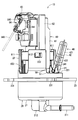
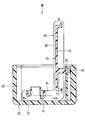
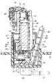
- FIG. 1 is a cross-sectional view illustrating a fuel pump module according to a first embodiment of the present disclosure
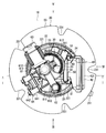
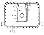
- FIG. 2 is a view of FIG. 1 as viewed from the direction of arrow II.
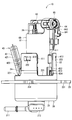
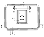
- FIG. 3 is a view of FIG. 2 as viewed from the direction of arrow III.
- FIG. 4 is a view of FIG. 2 as viewed from the direction of arrow IV.
- FIG. 5 is a view of FIG. 2 viewed from the direction of arrow V.
- FIG. 6 is a perspective view showing the fuel pump module according to the first embodiment of the present disclosure;
- FIG. 1 is a cross-sectional view illustrating a fuel pump module according to a first embodiment of the present disclosure
- FIG. 2 is a view of FIG. 1 as viewed from the direction of arrow II.
- FIG. 3 is a view of FIG. 2 as viewed from the direction of arrow III.
- FIG. 4 is a view of FIG. 2 as viewed from the direction of arrow IV.
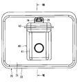
- FIG. 7 is a top view illustrating a part of the fuel pump module according to the second embodiment of the present disclosure; 8 is a cross-sectional view taken along line VIII-VIII in FIG.
- FIG. 9 is a cross-sectional view showing a part of a fuel pump module according to a third embodiment of the present disclosure, 10 is a cross-sectional view taken along line XX of FIG.
- FIG. 11 is a diagram when FIG. 9 is viewed from the direction of the arrow XI.
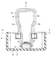
- FIG. 12 is a cross-sectional view showing a fuel pump module according to a fourth embodiment of the present disclosure.
- FIGS. 1-10 A fuel pump module according to a first embodiment of the present disclosure is shown in FIGS.
- the fuel pump module 10 is provided, for example, in a fuel tank 1 of a motorcycle.
- the fuel pump module 10 supplies the fuel in the fuel tank 1 to the engine 2 as a fuel supply target.
- the fuel pump module 10 includes a flange 20, a fuel pump 30, a filter 40, a holding unit 50, a housing 60, a bone member 70, and the like.
- the flange 20 is made of, for example, resin.
- the flange 20 includes a plate portion 21, a first tube portion 22, a flange portion 23, a support portion 24, and the like.
- the plate part 21 is formed in a disk shape.
- the first cylindrical portion 22 is formed to extend from the outer edge portion of the plate portion 21 in a cylindrical shape.
- the flange 20 has a cutout portion 221 formed so as to be cut out from the end portion of the first tube portion 22 opposite to the plate portion 21 toward the plate portion 21 side. As shown in FIG. 3, the notch portions 221 are formed at three locations in the circumferential direction of the first tube portion 22.
- the flange portion 23 is formed in an annular shape so as to extend radially outward from the outer wall between the plate portion 21 and the notch portion 221 of the first tube portion 22.
- the flange 20 has a recessed portion 231 formed so as to be recessed radially inward from the outer edge portion of the flange portion 23. As shown in FIG. 2, the recessed portions 231 are formed at five locations in the circumferential direction of the flange portion 23.
- the flange 20 has an opening 3 formed at the end opposite to the plate portion 21 of the first cylindrical portion 22 in the fuel tank 1 and formed on the lower side in the vertical direction of the fuel tank 1. It is provided so as to block.
- the opening 3 is formed so that the inner diameter is slightly larger than the outer diameter of the first tube portion 22.
- the flange 20 is provided so that the flange 23 abuts against the outer wall of the fuel tank 1.
- the flange 20 is fixed to the fuel tank 1 by the plate 4 and the fixing member 5.
- the plate 4 is formed in an annular shape from metal, for example, and is provided on the opposite side of the flange 23 from the fuel tank 1.
- the fixing member 5 is, for example, a screw having a head at one end, is inserted into a hole formed at a position corresponding to the recessed portion 231 of the plate 4, and is screwed into a screw hole formed in the outer wall of the fuel tank 1. Therefore, the flange 23 and the plate 4 are sandwiched between the head of the fixing member 5 and the outer wall of the fuel tank 1. Thereby, the flange 20 is fixed to the fuel tank 1.
- a rubber-made first seal member 6 formed in an annular shape is provided between the fuel tank 1 and the flange portion 23. Thereby, the space between the fuel tank 1 and the flange 23 is kept liquid-tight.
- the fuel pump 30 is formed in a substantially cylindrical shape, and is provided inside the first cylindrical portion 22 so that the shaft is parallel to the axis of the first cylindrical portion 22 of the flange 20.
- the fuel pump 30 has a first end located inside the first tube portion 22 and a second end located outside the first tube portion 22 in the axial direction.
- the fuel pump 30 includes a suction part 31, a discharge part 32, a motor 33, a motor terminal 34, an impeller 35, and the like.
- the suction part 31 is formed in a cylindrical shape at the first end of the fuel pump 30. That is, the suction portion 31 is located inside the first tube portion 22 of the flange 20 and in the vicinity of the plate portion 21.
- the discharge part 32 is formed in a cylindrical shape at the second end of the fuel pump 30.
- the motor 33 is an electric motor and is driven to rotate when electric power is supplied via the motor terminal 34.
- the motor 33 sucks fuel from the suction portion 31 by rotating the impeller 35, pressurizes it, and discharges it from the discharge portion 32.
- the filter 40 has a first filter part 41 and a second filter part 42.
- the filter 40 is formed of a multilayer mesh screen made of, for example, a polyamide-based resin.
- the filter 40 is formed into a flat bag shape by folding a long screen and welding the outer edge.
- the first filter portion 41 is formed flat and is provided between the plate portion 21 and the fuel pump 30 so that the surface direction is parallel to the plate portion 21 of the flange 20, and is connected to the suction portion 31 of the fuel pump 30. is doing.
- the second filter portion 42 is formed flat, and the outer edge portion is connected to the outer edge portion of the first filter portion 41 and is formed integrally with the first filter portion 41. That is, in this embodiment, the 1st filter part 41 and the 2nd filter part 42 are integrally formed by one screen.
- the filter 40 can collect foreign substances contained in the fuel sucked into the fuel pump 30 via the suction part 31.
- the second filter part 42 has an enlarged part 421 on the side opposite to the first filter part 41.
- the width of the end of the second filter unit 42 opposite to the first filter unit 41 is larger than the width of the end of the first filter unit 41. Is formed.
- the filter 40 is provided so that the second filter portion 42 contacts the notch portion 221 of the flange 20.
- the 2nd filter part 42 has the inclination part 422 in the 1st filter part 41 side of the expansion part 421, as shown in FIG.
- the inclined portion 422 is formed to be inclined with respect to the longitudinal direction of the second filter portion 42.
- the holding part 50 is formed in a rod shape by, for example, resin. As shown in FIG. 2, substantially cylindrical shaft portions 51 are formed at both ends of the holding portion 50. Two plate-like support portions 24 are formed inside the first cylindrical portion 22 of the flange 20. A fitting portion 241 having a shape corresponding to the shaft portion 51 is formed at the end of the support portion 24 opposite to the plate portion 21.
- the holding part 50 is provided on the support part 24 so that the shaft part 51 fits into the fitting part 241. At this time, the holding part 50 is in a state in which the second filter part 42 is sandwiched between the notch part 221 of the flange 20 and can hold the position of the second filter part 42 relative to the first tube part 22.
- the holding part 50 can be rotated relative to the support part 24 around the shaft part 51. Therefore, the holding unit 50 can follow changes in the position and shape of the second filter unit 42. Therefore, fluctuations in the position of the filter 40 can be effectively suppressed.
- the housing 60 includes a housing main body 61, a discharge passage portion 62, a pressure regulator 63, a sender gauge 64, and the like.
- the housing main body 61 is formed in a cylindrical shape by resin, for example.
- the fuel pump 30 is accommodated inside the housing body 61.
- the housing 60 has a protruding portion 611 formed so as to protrude radially outward from the outer wall of the housing body 61. As shown in FIG. 2, the protrusions 611 are formed at three locations in the circumferential direction of the housing body 61.
- a first claw portion 612 is formed at the tip of the protruding portion 611.
- the housing 60 is provided inside the first cylindrical portion 22 of the flange 20 in a state where the fuel pump 30 is accommodated inside the housing main body 61.
- the first claw portion 612 is fitted into the first hole portion 222 formed in the first tube portion 22.
- claw part 612 are couple
- the discharge passage portion 62 is formed to extend from the vicinity of the discharge portion 32 of the fuel pump 30 to the vicinity of the plate portion 21 of the flange 20 along the outer wall of the housing body 61.
- An end portion of the discharge passage portion 62 on the plate portion 21 side is connected to a first end of the discharge pipe portion 211 formed on the plate portion 21 of the flange 20.
- a second end of the discharge pipe portion 211 is connected to the engine 2 via a fuel pipe.
- the pressure regulator 63 is provided in the vicinity of the discharge portion 32 of the discharge passage portion 62.
- the pressure regulator 63 discharges the fuel in the discharge passage 62 to the outside, that is, into the fuel tank 1 when the pressure in the discharge passage 62 becomes a predetermined value or more. Thereby, the pressure in the discharge passage part 62, that is, the supply pressure of the fuel supplied from the discharge pipe part 211 to the engine 2 is maintained at a predetermined value.
- the sender gauge 64 is provided in the vicinity of the pressure regulator 63 of the housing main body 61. As shown in FIG. 3, the sender gauge 64 has a fixed portion 641, a rotating portion 642, a rod 643, and the like.
- the fixing part 641 is fixed to the housing body 61.
- the rotating part 642 is provided to be rotatable relative to the fixed part 641.
- the rod 643 is provided such that the first end is fixed to the rotating portion 642.
- a float (not shown) is attached to the second end of the rod 643. Since the float floats on the fuel level in the fuel tank 1, when the fuel level rises or falls, the rotating part 642 rotates relative to the fixed part 641.
- the sender gauge 64 outputs a signal corresponding to the relative rotational position of the rotating part 642 with respect to the fixed part 641.
- the housing 60 has a bracket 65 at the end of the housing body 61 on the suction portion 31 side.
- the bracket 65 is made of, for example, resin.
- the bracket 65 includes a bracket main body 651, an arm portion 652, and a second cylinder portion 653.
- the bracket body 651 is formed in a substantially disc shape.
- the arm portion 652 is formed to extend from the outer edge portion of the bracket body 651 in the plate thickness direction of the bracket body 651.
- three arm portions 652 are formed in the circumferential direction of the bracket body 651.
- the second cylinder portion 653 is formed in a cylindrical shape so as to extend from the bracket main body 651 in the direction opposite to the arm portion 652.
- the space inside the second cylindrical portion 653 connects the first surface and the second surface of the bracket body 651.
- the bracket 65 is assembled integrally with the fuel pump 30 so that the suction part 31 of the fuel pump 30 is fitted inside the second cylinder part 653.
- the housing 60 has a second claw portion 613 formed so as to protrude from the outer wall of the housing main body 61.
- Three second claw portions 613 correspond to the arm portions 652 and are formed in the circumferential direction of the housing body 61.
- the second claw portion 613 is fitted into the second hole portion 654 formed in the arm portion 652.
- the second hole portion 654 and the second claw portion 613 are coupled by a snap fit. As a result, the fuel pump 30 is restricted from falling off from the inside of the housing body 61.
- the bone member 70 is provided in a filter 40 formed in a bag shape by a resin screen.
- the bone member 70 is made of, for example, resin.
- the bone member 70 has a first bone part 71, a second bone part 72, and a connection part 73.
- the first bone part 71 is provided inside the first filter part 41 and is formed so as to be able to hold the outer shape of the first filter part 41 formed flat.
- the 2nd bone part 72 is provided inside the 2nd filter part 42, and is formed so that the external shape of the 2nd filter part 42 formed flatly can be hold
- the connection portion 73 is formed integrally with the first bone portion 71 and the second bone portion 72 so as to connect the first bone portion 71 and the second bone portion 72.
- the connecting portion 73 is formed to be deformable. Therefore, the first bone portion 71 and the second bone portion 72 can move relative to each other around the connection portion 73.
- the filter 40 can be formed so that the angle ⁇ formed by the first filter portion 41 and the second filter portion 42 is a predetermined angle.
- the filter 40 is formed so that ⁇ is an obtuse angle, that is, an angle that is larger than a right angle and smaller than two right angles.
- ⁇ is preferably about 95 to 110 degrees, for example. If ⁇ is smaller than 95 degrees, for example, the height that is the size in the direction perpendicular to the first filter portion 41 of the filter 40 may be increased.
- ⁇ is greater than 110 degrees, for example, the width that is the size in the direction parallel to the first filter portion 41 of the filter 40 may increase.
- ⁇ is set to about 106 degrees, for example. Therefore, the width of the filter 40 in the direction parallel to the first filter part 41 and the height of the filter 40 in the direction perpendicular to the first filter part 41 can be suppressed.
- the filter 40 has a cylindrical member 43 on one surface of the first filter portion 41.
- the cylindrical member 43 is formed in a cylindrical shape with, for example, resin.
- the cylindrical member 43 is provided so as to be connected to a cylindrical portion exposed from the first filter portion 41 of the first bone portion 71.
- the space inside the cylinder member 43 connects the inside and the outside of the first filter portion 41.
- the filter 40 is attached to the bracket 65 of the housing 60 by being inserted so that the cylindrical member 43 is positioned outside the second cylindrical portion 653 of the bracket 65.
- the first filter portion 41 is connected to the suction portion 31 of the fuel pump 30 via the tubular member 43 and the second tubular portion 653.
- a second seal member 66 made of an annular rubber is provided between the second cylinder portion 653 and the cylinder member 43. Thereby, the space between the second cylinder portion 653 and the cylinder member 43 is kept liquid-tight.
- the filter 40 is formed such that ⁇ is an obtuse angle, and the center of the second filter portion 42 is provided in a state of being in contact with the notch portion 221 of the flange 20. . Therefore, the end of the second filter portion 42 on the first filter portion 41 side is located inside the first tube portion 22 of the flange 20, but the end of the second filter portion 42 opposite to the first filter portion 41. A part will be in the state located in the outer side of the 1st cylinder part 22.
- the motorcycle includes an electronic control unit (ECU) 7.
- ECU electronice control unit
- ECU7 is a small computer which has CPU, ROM, RAM, I / O etc., for example.
- the ECU 7 performs calculations according to a program stored in the ROM based on signals from sensors and the like provided in each part of the motorcycle, and controls the operation of devices and devices in each part of the motorcycle.
- a connector portion 212 is provided on the plate portion 21 of the flange 20.
- the connector part 212 has a plurality of terminals inside. The terminals are electrically connected to the motor terminal 34 and the sender gauge 64, respectively.
- ECU7 is connected to the connector part 212 by the wire harness which is not shown in figure.
- the ECU 7 can control the operation of the fuel pump 30 by controlling the power supplied from the battery (not shown) to the motor 33 via the wire harness. Thereby, the ECU 7 can control the amount of fuel supplied to the engine 2.
- the sender gauge 64 outputs a signal corresponding to the relative rotational position of the rotating part 642 with respect to the fixed part 641 to the ECU 7 via the connector part 212 and the wire harness.
- the ECU 7 can detect the height of the fuel level in the fuel tank 1, that is, the remaining amount of fuel.
- the method for manufacturing the fuel pump module 10 includes the following steps.
- the bracket 65 is assembled integrally with the fuel pump 30 so that the suction part 31 of the fuel pump 30 is fitted inside the second cylinder part 653. Subsequently, the fuel pump 30 integrated with the bracket 65 is inserted into the housing main body 61. At this time, the second claw portion 613 of the housing main body 61 is fitted into the second hole portion 654 of the arm portion 652 of the bracket 65. Thereby, the bracket 65 is fixed to the housing 60. As a result, the fuel pump 30 is held in the housing body 61 and is prevented from falling off from the inside of the housing body 61. This process is a fuel pump assembly process.
- the filter 40 is assembled to the bracket 65 of the housing 60 by fitting the second seal member 66 outside the second cylinder part 653 and inserting the cylinder member 43 so as to be positioned outside the second cylinder part 653. This process is a filter assembling process.
- the housing 60 in a state where the fuel pump 30 and the filter 40 are assembled is inserted into the first cylindrical portion 22 of the flange 20. Accordingly, the first filter portion 41 abuts on the plate portion 21 of the flange 20, and the center of the second filter portion 42 abuts on the notch portion 221 of the flange 20. Further, the housing 60 is fixed in the flange 20 by fitting the first claw portion 612 into the first hole portion 222 of the flange 20. At this time, the end of the second filter portion 42 opposite to the first filter portion 41 is located outside the first tube portion 22. This process is a housing insertion process.
- the shaft part 51 of the holding part 50 is fitted to the fitting part 241 of the support part 24 of the flange 20.
- the second filter part 42 is sandwiched between the holding part 50 and the notch part 221. This process is a holding part assembly process.
- the fuel pump module 10 is attached to the fuel tank 1 through the following steps.
- the end portion of the second filter portion 42 opposite to the first filter portion 41 is located outside the first tube portion 22. Therefore, the second filter part 42 is deformed so that the end of the second filter part 42 opposite to the first filter part 41 is located inside the outer wall of the first tube part 22, and the opening part of the fuel tank 1 is formed. 3 is ready for insertion.
- This process is a filter deformation process.
- the fuel pump module 10 is inserted into the opening 3 of the fuel tank 1 with the second filter portion 42 being deformed in the filter deformation step. Thereby, the deformation of the second filter part 42 is released in the fuel tank 1, and the end of the second filter part 42 opposite to the first filter part 41 is located outside the first tube part 22. become.
- This process is an insertion process.
- the flange 4 of the flange 20 is fixed to the outer wall of the fuel tank 1 by the plate 4 and the fixing member 5. Thereby, the attachment of the fuel pump module 10 to the fuel tank 1 is completed.
- This process is a fixing process.
- the inclined portion 422 of the second filter portion 42 comes into contact with and is guided by the opening 3 of the fuel tank 1. Therefore, as in the present embodiment, an enlarged portion 421 is formed on the opposite side of the second filter portion 42 from the first filter portion 41, and the first filter portion 41 of the second filter portion 42 is within the fuel tank 1.
- the fuel pump module 10 can be smoothly removed from the fuel tank 1 even if the opposite end is located outside the first tube portion 22.
- the flange 20 has the plate portion 21 and the first tube portion 22 that extends in a cylindrical shape from the outer edge portion of the plate portion 21.
- the flange 20 is provided so that the end portion of the first cylindrical portion 22 opposite to the plate portion 21 is located in the fuel tank 1 and closes the opening 3 formed on the lower side in the vertical direction of the fuel tank 1.
- the fuel pump 30 is provided inside the first cylindrical portion 22 of the flange 20.
- the fuel pump 30 includes a suction portion 31 that sucks fuel in the fuel tank 1 and a discharge portion 32 that discharges fuel that has been sucked and pressurized from the suction portion 31.
- the filter 40 is a flat first filter portion 41 provided between the plate portion 21 and the fuel pump 30 so as to be parallel to the plate portion 21 of the flange 20 and connected to the suction portion 31 of the fuel pump 30.
- the outer edge part has the flat 2nd filter part 42 formed integrally with the 1st filter part 41 while connecting with the outer edge part of the 1st filter part 41. As shown in FIG.
- the filter 40 can collect foreign substances contained in the fuel sucked into the fuel pump 30.
- the filter 40 is formed so that the angle ⁇ formed by the first filter portion 41 and the second filter portion 42 is a predetermined angle.
- the filter 40 includes a first filter portion 41 provided between the plate portion 21 of the flange 20 and the fuel pump 30, and a second filter portion 42 provided so as to be connected to the first filter portion 41. Therefore, the surface area of the filter 40 can be increased. Therefore, the foreign matter collection effect by the filter 40 can be improved.
- the filter 40 is formed so that the angle ⁇ formed by the first filter portion 41 and the second filter portion 42 becomes an obtuse angle. Therefore, the filter 40 is suppressed while suppressing the width of the filter 40 in the direction parallel to the first filter part 41 and the height of the filter 40 in the direction perpendicular to the first filter part 41.
- the surface area of can be increased. Therefore, the foreign matter collecting effect by the filter 40 can be further improved while downsizing the fuel pump module 10.
- the second filter portion 42 is formed so that the width of the end portion on the side opposite to the first filter portion 41 is larger than the width of the end portion on the first filter portion 41 side. Thereby, the surface area of the 2nd filter part 42 can be enlarged, and the collection effect of the foreign material by the filter 40 can further be improved.
- the flange 20 has a cutout portion 221 formed so as to be cut out from the end portion of the first tube portion 22 opposite to the plate portion 21 toward the plate portion 21 side.
- the filter 40 is provided so that the second filter portion 42 contacts the notch portion 221. Therefore, the notch part 221 can regulate the fall of the second filter part 42. Further, the second filter part 42 is brought into contact with the notch part 221 so that the end of the second filter part 42 opposite to the first filter part 41 is positioned outside the first tube part 22 of the flange 20. Accordingly, the filter 40 having a predetermined physique can be provided on the flange 20 while reducing the outer diameter of the first cylindrical portion 22.
- a holding unit 50 that is provided so as to sandwich the second filter unit 42 between the first tube unit 22 and can hold the position of the second filter unit 42 with respect to the first tube unit 22 is provided. It has more. Thereby, the fluctuation
- the holding part 50 is provided on the support part 24 of the flange 20.
- the filter 40 is installed on the flange 20 and then assembled to the support portion 24.
- the first bone portion 71 provided inside the first filter portion 41 and capable of holding the outer shape of the first filter portion 41, and the second filter portion 42 provided inside the second filter portion 42.
- a bone member 70 having a second bone portion 72 capable of holding the outer shape and a connection portion 73 that connects the first bone portion 71 and the second bone portion 72 is further provided.
- the bone member 70 can prevent the outer shape of the filter 40 from being deformed or crushed, and can suppress a decrease in the effect of collecting foreign matter by the filter 40.
- FIGS. 1 A part of the fuel pump module according to the second embodiment of the present disclosure is shown in FIGS.
- the second embodiment differs from the first embodiment in the shapes of flanges and bone members.
- the flange 20 has an engaged portion 25 formed in the first cylindrical portion 22. More specifically, the engaged portion 25 is integrally formed with the first tube portion 22 so as to extend in a direction parallel to the axis of the first tube portion 22 along the inner wall of the first tube portion 22 by, for example, resin. Is formed.
- the first tube portion 22 is formed in a rectangular tube shape.
- the plate portion 21 is formed in a rectangular plate shape.
- the opening 3 of the fuel tank 1 corresponds to the shape of the first tube portion 22 and is formed in a rectangular shape.
- the bone member 70 has an engaging portion 74 formed on the second bone portion 72 so as to be engageable with the engaged portion 25. More specifically, the engaging portion 74 is integrally formed with the second bone portion 72 so as to extend from the second bone portion 72 and be exposed to the outside of the second filter portion 42 by, for example, resin.
- the second filter portion 42 when the filter 40 is inserted inside the first tube portion 22 of the flange 20, the second filter portion 42 is moved to the first tube portion while aligning the positions of the engaging portion 74 and the engaged portion 25. Move in a direction parallel to the 22 axes. Thereby, as shown in FIGS. 7 and 8, the engaging portion 74 and the engaged portion 25 are engaged, and the second filter portion 42 is in a stable position with respect to the first tube portion 22.
- the filter 40 is formed so that the angle ⁇ formed by the first filter portion 41 and the second filter portion 42 is a right angle. Thereby, the surface area of the filter 40 can be increased while suppressing the width of the filter 40 in the direction parallel to the first filter portion 41.
- the flange 20 has the engaged portion 25 formed in the first cylindrical portion 22.
- the bone member 70 has an engaging portion 74 formed on the second bone portion 72 so as to be engageable with the engaged portion 25.
- the engaging portion 74 and the engaged portion 25 are engaged, the position of the second filter portion 42 with respect to the first tube portion 22 is stabilized. Thereby, the fluctuation
- the engaged portion 25 is formed integrally with the first tube portion 22, and the engaging portion 74 is formed integrally with the second bone portion 72. Therefore, the position of the filter 40 can be stabilized without increasing the number of members.
- FIGS. 1 and 2 A portion of a fuel pump module according to a third embodiment of the present disclosure is shown in FIGS.
- the third embodiment differs from the first embodiment in the shape of the flange and the like.
- the flange 20 has a locking portion 26 formed on the first tube portion 22 so that the outer edge portion of the second filter portion 42 can be locked. More specifically, the locking portion 26 is formed integrally with the first cylindrical portion 22 so as to protrude from the inner wall of the end portion of the first cylindrical portion 22 opposite to the plate portion 21, for example, with resin. . A total of two locking portions 26 are formed at positions corresponding to the outer edge portions of the second filter portion 42 provided on the flange 20.
- the first tube portion 22 is formed in a rectangular tube shape.
- the plate portion 21 is formed in a rectangular plate shape.
- the opening 3 of the fuel tank 1 corresponds to the shape of the first tube portion 22 and is formed in a rectangular shape.
- the second filter portion 42 when the filter 40 is inserted inside the first cylindrical portion 22 of the flange 20, the second filter portion 42 is moved to the second filter portion 42 while aligning the positions of the outer edge portion of the second filter portion 42 and the locking portion 26. It is moved in a direction parallel to the axis of the one cylindrical portion 22. As a result, as shown in FIGS. 9 and 10, the locking portion 26 locks the outer edge portion of the second filter portion 42, and the second filter portion 42 is in a stable position with respect to the first tube portion 22. .
- the filter 40 is formed so that the angle formed by the first filter portion 41 and the second filter portion 42 is a right angle. Thereby, the surface area of the filter 40 can be increased while suppressing the width of the filter 40 in the direction parallel to the first filter portion 41.
- the flange 20 has the locking portion 26 formed on the first cylindrical portion 22 so that the outer edge portion of the second filter portion 42 can be locked.
- the locking part 26 locks the outer edge part of the second filter part 42
- the position of the second filter part 42 relative to the first tube part 22 is stabilized.
- variation of the position with respect to the flange 20 and the fuel pump 30 of the filter 40 can be suppressed.
- the connection state between the suction part 31 of the fuel pump 30 and the first filter part 41 can be kept good.
- the locking portion 26 is formed integrally with the first tube portion 22. Therefore, the position of the filter 40 can be stabilized without increasing the number of members.
- FIG. 4 A portion of a fuel pump module according to a fourth embodiment of the present disclosure is shown in FIG.
- the fourth embodiment differs from the first embodiment in the configuration of the holding portion and the like.
- the holding portion 50 is provided in the housing 60. More specifically, the holding part 50 is integrally formed with the housing body 61 so that the second filter part 42 can be sandwiched between the notch part 221 of the flange 20.
- the flange 20 does not have the support part 24 shown in the first embodiment.
- maintenance part 50 does not have the axial part 51 shown by 1st Embodiment.
- the second filter portion 42 when the housing 60 in which the holding portion 50 is formed is inserted into the first cylindrical portion 22 of the flange 20 together with the fuel pump 30 and the filter 40, the second filter portion 42 has the notch portion 221 and the holding portion. 50 between them. Thereby, the 2nd filter part 42 will be in the state where the position with respect to the 1st cylinder part 22 was stabilized.
- the present embodiment includes the housing 60 provided inside the first cylinder portion 22 so as to accommodate the fuel pump 30.
- the holding part 50 is provided in the housing 60.
- the position of the second filter part 42 relative to the first tube part 22 is stabilized.
- variation of the position with respect to the flange 20 and the fuel pump 30 of the filter 40 can be suppressed.
- the connection state between the suction part 31 of the fuel pump 30 and the first filter part 41 can be kept good.
- the holding portion 50 is formed integrally with the housing 60. Therefore, the position of the filter 40 can be stabilized without increasing the number of members.
- the angle formed by the first filter unit and the second filter unit is set to an obtuse angle or a right angle.
- the angle formed by the first filter unit and the second filter unit may be set to any angle such as an acute angle or a right angle.
- the second filter portion may be formed such that the width of the end portion on the side opposite to the first filter portion is equal to or less than the width of the end portion on the first filter portion side.
- the flange may have any number of notches in the circumferential direction of the cylindrical portion. Moreover, the 2nd filter part does not need to contact
- the holding portion is formed integrally with the housing.
- the holding portion may be formed separately from the housing and provided in the housing.
- the holding unit may not be provided.
- the pressure regulator and the sender gauge may not be provided. Moreover, it is good also as a structure which does not provide a housing but hold
- the bone member in the above-described embodiment, an example in which the bone member is provided inside the filter has been described.
- the bone member may be provided outside the filter.
- the first bone portion holds the outer shape of the first filter portion outside the first filter portion
- the second bone portion holds the outer shape of the second filter portion outside the second filter portion.
- the bone member may not be provided.
- the filter may be provided in a state where the first filter portion is separated from the plate portion of the flange.
- the filter (first filter portion, second filter portion) is not limited to polyamide-based resin, and for example, a non-woven fabric or the like, as long as it can collect foreign matter contained in the fuel, It may be formed of any material.
- the motor of the fuel pump may be any motor such as a motor with a brush or a brushless motor.
- the fuel pump module of the present disclosure is not limited to a motorcycle engine, but can be a fuel supply target for an automobile engine, other vehicle engines, or other devices driven by fluid fuel.
- the present disclosure has a high effect of collecting foreign matters by a filter and is small, and is particularly suitable for installation in a fuel tank having a small internal space.
- the present disclosure is not limited to the above embodiment, and can be implemented in various forms without departing from the gist thereof.
Landscapes
- Engineering & Computer Science (AREA)
- Chemical & Material Sciences (AREA)
- Combustion & Propulsion (AREA)
- Mechanical Engineering (AREA)
- General Engineering & Computer Science (AREA)
- Cooling, Air Intake And Gas Exhaust, And Fuel Tank Arrangements In Propulsion Units (AREA)
- Filtration Of Liquid (AREA)
Priority Applications (1)
| Application Number | Priority Date | Filing Date | Title |
|---|---|---|---|
| CN201580005258.3A CN106414988B (zh) | 2014-01-22 | 2015-01-09 | 燃料泵模块 |
Applications Claiming Priority (2)
| Application Number | Priority Date | Filing Date | Title |
|---|---|---|---|
| JP2014009573A JP6194803B2 (ja) | 2014-01-22 | 2014-01-22 | 燃料ポンプモジュール |
| JP2014-009573 | 2014-01-22 |
Publications (1)
| Publication Number | Publication Date |
|---|---|
| WO2015111375A1 true WO2015111375A1 (ja) | 2015-07-30 |
Family
ID=53681190
Family Applications (1)
| Application Number | Title | Priority Date | Filing Date |
|---|---|---|---|
| PCT/JP2015/000073 Ceased WO2015111375A1 (ja) | 2014-01-22 | 2015-01-09 | 燃料ポンプモジュール |
Country Status (3)
| Country | Link |
|---|---|
| JP (1) | JP6194803B2 (enExample) |
| CN (1) | CN106414988B (enExample) |
| WO (1) | WO2015111375A1 (enExample) |
Cited By (1)
| Publication number | Priority date | Publication date | Assignee | Title |
|---|---|---|---|---|
| JP7134293B1 (ja) | 2021-04-27 | 2022-09-09 | 三菱電機株式会社 | 燃料供給装置 |
Families Citing this family (1)
| Publication number | Priority date | Publication date | Assignee | Title |
|---|---|---|---|---|
| JP6987203B1 (ja) * | 2020-11-04 | 2021-12-22 | 三菱電機株式会社 | 燃料供給装置 |
Citations (7)
| Publication number | Priority date | Publication date | Assignee | Title |
|---|---|---|---|---|
| JPH03225061A (ja) * | 1990-01-30 | 1991-10-04 | Nissan Motor Co Ltd | 自動車用燃料タンク |
| JP2000008986A (ja) * | 1998-06-24 | 2000-01-11 | Aisan Ind Co Ltd | インタンク式ポンプ用フィルター |
| JP2002303217A (ja) * | 2001-04-09 | 2002-10-18 | Keihin Corp | 燃料供給装置 |
| WO2003044357A1 (fr) * | 2001-11-20 | 2003-05-30 | Mitsubishi Denki Kabushiki Kaisha | Systeme d'alimentation en carburant pour vehicule |
| JP2007255376A (ja) * | 2006-03-24 | 2007-10-04 | Denso Corp | 燃料供給装置 |
| JP2009209841A (ja) * | 2008-03-05 | 2009-09-17 | Denso Corp | ポンプモジュール |
| US20100065023A1 (en) * | 2008-09-15 | 2010-03-18 | Gm Global Technology Operations, Inc. | Anti-Clogging Fuel Pump Module |
Family Cites Families (2)
| Publication number | Priority date | Publication date | Assignee | Title |
|---|---|---|---|---|
| JP3225061B2 (ja) * | 1991-07-19 | 2001-11-05 | アンリツ株式会社 | 符号誤り検出装置 |
| JP5414483B2 (ja) * | 2009-12-01 | 2014-02-12 | 三菱電機株式会社 | 燃料供給装置 |
-
2014
- 2014-01-22 JP JP2014009573A patent/JP6194803B2/ja active Active
-
2015
- 2015-01-09 CN CN201580005258.3A patent/CN106414988B/zh active Active
- 2015-01-09 WO PCT/JP2015/000073 patent/WO2015111375A1/ja not_active Ceased
Patent Citations (7)
| Publication number | Priority date | Publication date | Assignee | Title |
|---|---|---|---|---|
| JPH03225061A (ja) * | 1990-01-30 | 1991-10-04 | Nissan Motor Co Ltd | 自動車用燃料タンク |
| JP2000008986A (ja) * | 1998-06-24 | 2000-01-11 | Aisan Ind Co Ltd | インタンク式ポンプ用フィルター |
| JP2002303217A (ja) * | 2001-04-09 | 2002-10-18 | Keihin Corp | 燃料供給装置 |
| WO2003044357A1 (fr) * | 2001-11-20 | 2003-05-30 | Mitsubishi Denki Kabushiki Kaisha | Systeme d'alimentation en carburant pour vehicule |
| JP2007255376A (ja) * | 2006-03-24 | 2007-10-04 | Denso Corp | 燃料供給装置 |
| JP2009209841A (ja) * | 2008-03-05 | 2009-09-17 | Denso Corp | ポンプモジュール |
| US20100065023A1 (en) * | 2008-09-15 | 2010-03-18 | Gm Global Technology Operations, Inc. | Anti-Clogging Fuel Pump Module |
Cited By (2)
| Publication number | Priority date | Publication date | Assignee | Title |
|---|---|---|---|---|
| JP7134293B1 (ja) | 2021-04-27 | 2022-09-09 | 三菱電機株式会社 | 燃料供給装置 |
| JP2022168932A (ja) * | 2021-04-27 | 2022-11-09 | 三菱電機株式会社 | 燃料供給装置 |
Also Published As
| Publication number | Publication date |
|---|---|
| CN106414988B (zh) | 2019-11-12 |
| CN106414988A (zh) | 2017-02-15 |
| JP6194803B2 (ja) | 2017-09-13 |
| JP2015137589A (ja) | 2015-07-30 |
Similar Documents
| Publication | Publication Date | Title |
|---|---|---|
| CN108603470B (zh) | 燃料供给装置 | |
| JP4179179B2 (ja) | 燃料供給装置 | |
| US7458365B2 (en) | Fuel supply system with a cooling plate | |
| CN108603468B (zh) | 燃料箱用盖构件 | |
| US8915233B2 (en) | Fuel supply equipment | |
| US20190078541A1 (en) | Fuel supply device | |
| US9567956B2 (en) | Fuel pump module | |
| JP2011122541A (ja) | ベーン式ポンプおよびそれを用いたエバポリークチェックシステム | |
| JP6992669B2 (ja) | 燃料供給装置 | |
| EP2532876B1 (en) | Fuel supply device | |
| JP6194803B2 (ja) | 燃料ポンプモジュール | |
| JP2004257347A (ja) | 燃料供給装置 | |
| US9574530B2 (en) | Fuel pump module and method of manufacturing the same | |
| CN108884797B (zh) | 压力调节器及燃料供给装置 | |
| US20150059708A1 (en) | Fuel pump module | |
| JP5783428B2 (ja) | 燃料ポンプモジュール | |
| CN111433449A (zh) | 燃料供给装置 | |
| JP5880979B2 (ja) | 燃料ポンプモジュール | |
| EP4658884A1 (en) | Integrated grommet filter | |
| JP2007126981A (ja) | 燃料供給装置 | |
| JP5667769B2 (ja) | 燃料供給装置 | |
| JP5046137B2 (ja) | ベーン式ポンプおよびそれを用いたエバポリークチェックシステム | |
| JP2005214122A (ja) | 燃料供給装置 | |
| CN111164298B (zh) | 燃料吸入口构件 | |
| JP6138369B2 (ja) | 燃料供給装置 |
Legal Events
| Date | Code | Title | Description |
|---|---|---|---|
| 121 | Ep: the epo has been informed by wipo that ep was designated in this application |
Ref document number: 15740949 Country of ref document: EP Kind code of ref document: A1 |
|
| NENP | Non-entry into the national phase |
Ref country code: DE |
|
| 122 | Ep: pct application non-entry in european phase |
Ref document number: 15740949 Country of ref document: EP Kind code of ref document: A1 |