WO2015111375A1 - Fuel pump module - Google Patents
Fuel pump module Download PDFInfo
- Publication number
- WO2015111375A1 WO2015111375A1 PCT/JP2015/000073 JP2015000073W WO2015111375A1 WO 2015111375 A1 WO2015111375 A1 WO 2015111375A1 JP 2015000073 W JP2015000073 W JP 2015000073W WO 2015111375 A1 WO2015111375 A1 WO 2015111375A1
- Authority
- WO
- WIPO (PCT)
- Prior art keywords
- filter
- fuel pump
- fuel
- flange
- pump module
- Prior art date
Links
Images


Classifications
-
- F—MECHANICAL ENGINEERING; LIGHTING; HEATING; WEAPONS; BLASTING
- F02—COMBUSTION ENGINES; HOT-GAS OR COMBUSTION-PRODUCT ENGINE PLANTS
- F02M—SUPPLYING COMBUSTION ENGINES IN GENERAL WITH COMBUSTIBLE MIXTURES OR CONSTITUENTS THEREOF
- F02M37/00—Apparatus or systems for feeding liquid fuel from storage containers to carburettors or fuel-injection apparatus; Arrangements for purifying liquid fuel specially adapted for, or arranged on, internal-combustion engines
- F02M37/04—Feeding by means of driven pumps
- F02M37/08—Feeding by means of driven pumps electrically driven
- F02M37/10—Feeding by means of driven pumps electrically driven submerged in fuel, e.g. in reservoir
- F02M37/103—Mounting pumps on fuel tanks
-
- F—MECHANICAL ENGINEERING; LIGHTING; HEATING; WEAPONS; BLASTING
- F02—COMBUSTION ENGINES; HOT-GAS OR COMBUSTION-PRODUCT ENGINE PLANTS
- F02M—SUPPLYING COMBUSTION ENGINES IN GENERAL WITH COMBUSTIBLE MIXTURES OR CONSTITUENTS THEREOF
- F02M37/00—Apparatus or systems for feeding liquid fuel from storage containers to carburettors or fuel-injection apparatus; Arrangements for purifying liquid fuel specially adapted for, or arranged on, internal-combustion engines
- F02M37/22—Arrangements for purifying liquid fuel specially adapted for, or arranged on, internal-combustion engines, e.g. arrangements in the feeding system
- F02M37/32—Arrangements for purifying liquid fuel specially adapted for, or arranged on, internal-combustion engines, e.g. arrangements in the feeding system characterised by filters or filter arrangements
- F02M37/44—Filters structurally associated with pumps
-
- F—MECHANICAL ENGINEERING; LIGHTING; HEATING; WEAPONS; BLASTING
- F02—COMBUSTION ENGINES; HOT-GAS OR COMBUSTION-PRODUCT ENGINE PLANTS
- F02M—SUPPLYING COMBUSTION ENGINES IN GENERAL WITH COMBUSTIBLE MIXTURES OR CONSTITUENTS THEREOF
- F02M37/00—Apparatus or systems for feeding liquid fuel from storage containers to carburettors or fuel-injection apparatus; Arrangements for purifying liquid fuel specially adapted for, or arranged on, internal-combustion engines
- F02M37/22—Arrangements for purifying liquid fuel specially adapted for, or arranged on, internal-combustion engines, e.g. arrangements in the feeding system
- F02M37/32—Arrangements for purifying liquid fuel specially adapted for, or arranged on, internal-combustion engines, e.g. arrangements in the feeding system characterised by filters or filter arrangements
- F02M37/50—Filters arranged in or on fuel tanks
-
- F—MECHANICAL ENGINEERING; LIGHTING; HEATING; WEAPONS; BLASTING
- F02—COMBUSTION ENGINES; HOT-GAS OR COMBUSTION-PRODUCT ENGINE PLANTS
- F02M—SUPPLYING COMBUSTION ENGINES IN GENERAL WITH COMBUSTIBLE MIXTURES OR CONSTITUENTS THEREOF
- F02M37/00—Apparatus or systems for feeding liquid fuel from storage containers to carburettors or fuel-injection apparatus; Arrangements for purifying liquid fuel specially adapted for, or arranged on, internal-combustion engines
- F02M37/22—Arrangements for purifying liquid fuel specially adapted for, or arranged on, internal-combustion engines, e.g. arrangements in the feeding system
- F02M37/32—Arrangements for purifying liquid fuel specially adapted for, or arranged on, internal-combustion engines, e.g. arrangements in the feeding system characterised by filters or filter arrangements
- F02M37/34—Arrangements for purifying liquid fuel specially adapted for, or arranged on, internal-combustion engines, e.g. arrangements in the feeding system characterised by filters or filter arrangements by the filter structure, e.g. honeycomb, mesh or fibrous
Definitions
- the present disclosure relates to a fuel pump module that supplies fuel in a fuel tank to a fuel supply target.
- the fuel pump module of Patent Document 1 is provided so as to close an opening formed on the lower side in the vertical direction of the fuel tank with a flange.
- the fuel pump module of Patent Document 1 has a flat filter that collects foreign matters contained in the fuel sucked into the suction portion of the fuel pump.
- the fuel pump module is provided in the fuel tank so that the surface direction of the filter is in a state along the vertical direction. Since the fuel tank of a motorcycle is small and the height of the internal space is small, the vertical size of the filter, that is, the height may be limited. For this reason, a sufficient surface area of the filter cannot be secured, and the effect of collecting foreign matters by the filter may be reduced. Further, if the vertical size of the filter is increased in order to ensure the surface area of the filter, the fuel pump module may be increased in size.
- the present disclosure has been made in view of the above-described matters, and an object thereof is to provide a small fuel pump module that has a high effect of collecting foreign matter by a filter.
- the fuel pump module supplies the fuel in the fuel tank to the fuel supply target, and includes a flange, a fuel pump, and a filter.
- the flange has a plate portion and a cylindrical portion extending in a cylindrical shape from the outer edge portion of the plate portion.
- the flange is provided so that an end portion of the cylinder portion opposite to the plate portion is located in the fuel tank and closes an opening formed on the lower side in the vertical direction of the fuel tank.
- the fuel pump is provided inside the cylinder part of the flange.
- the fuel pump has a suction portion that sucks fuel in the fuel tank and a discharge portion that discharges fuel that is sucked and pressurized from the suction portion.
- the filter has a flat first filter portion that is provided between the plate portion and the fuel pump so that the surface direction is parallel to the plate portion of the flange and is connected to the suction portion of the fuel pump, and the outer edge portion is the first filter. And a flat second filter portion formed integrally with the first filter portion.
- the filter can collect foreign substances contained in the fuel sucked into the fuel pump.
- the filter is formed so that the angle which the 1st filter part and the 2nd filter part make may become a predetermined angle.
- the filter includes the first filter portion provided between the plate portion of the flange and the fuel pump, and the second filter portion provided so as to be connected to the first filter portion. The surface area of can be increased. Therefore, the effect of collecting foreign matter by the filter can be improved.
- the filter when the filter is formed so that the angle formed by the first filter portion and the second filter portion is, for example, a right angle, the width of the filter in the direction parallel to the first filter portion is suppressed and the filter is suppressed.
- the surface area of can be increased.
- the filter when the filter is formed so that the angle formed by the first filter portion and the second filter portion is, for example, two right angles, the height of the filter in the direction perpendicular to the first filter portion is suppressed.
- the surface area of the filter can be increased.
- the filter when the filter is formed so that the angle formed by the first filter portion and the second filter portion is, for example, an obtuse angle, that is, an angle larger than a right angle and smaller than two right angles, the direction parallel to the first filter portion of the filter.
- the surface area of the filter can be increased while suppressing the width that is the size of the filter and the height that is the size in the direction perpendicular to the first filter portion of the filter. Therefore, it is possible to further improve the effect of collecting foreign matters by the filter while downsizing the fuel pump module.
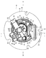
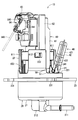
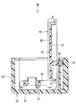
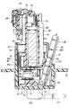
- FIG. 1 is a cross-sectional view illustrating a fuel pump module according to a first embodiment of the present disclosure
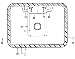
- FIG. 2 is a view of FIG. 1 as viewed from the direction of arrow II.
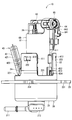
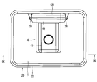
- FIG. 3 is a view of FIG. 2 as viewed from the direction of arrow III.
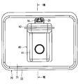
- FIG. 4 is a view of FIG. 2 as viewed from the direction of arrow IV.
- FIG. 5 is a view of FIG. 2 viewed from the direction of arrow V.
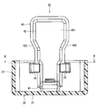
- FIG. 6 is a perspective view showing the fuel pump module according to the first embodiment of the present disclosure;
- FIG. 1 is a cross-sectional view illustrating a fuel pump module according to a first embodiment of the present disclosure
- FIG. 2 is a view of FIG. 1 as viewed from the direction of arrow II.
- FIG. 3 is a view of FIG. 2 as viewed from the direction of arrow III.
- FIG. 4 is a view of FIG. 2 as viewed from the direction of arrow IV.
- FIG. 7 is a top view illustrating a part of the fuel pump module according to the second embodiment of the present disclosure; 8 is a cross-sectional view taken along line VIII-VIII in FIG.
- FIG. 9 is a cross-sectional view showing a part of a fuel pump module according to a third embodiment of the present disclosure, 10 is a cross-sectional view taken along line XX of FIG.
- FIG. 11 is a diagram when FIG. 9 is viewed from the direction of the arrow XI.
- FIG. 12 is a cross-sectional view showing a fuel pump module according to a fourth embodiment of the present disclosure.
- FIGS. 1-10 A fuel pump module according to a first embodiment of the present disclosure is shown in FIGS.
- the fuel pump module 10 is provided, for example, in a fuel tank 1 of a motorcycle.
- the fuel pump module 10 supplies the fuel in the fuel tank 1 to the engine 2 as a fuel supply target.
- the fuel pump module 10 includes a flange 20, a fuel pump 30, a filter 40, a holding unit 50, a housing 60, a bone member 70, and the like.
- the flange 20 is made of, for example, resin.
- the flange 20 includes a plate portion 21, a first tube portion 22, a flange portion 23, a support portion 24, and the like.
- the plate part 21 is formed in a disk shape.
- the first cylindrical portion 22 is formed to extend from the outer edge portion of the plate portion 21 in a cylindrical shape.
- the flange 20 has a cutout portion 221 formed so as to be cut out from the end portion of the first tube portion 22 opposite to the plate portion 21 toward the plate portion 21 side. As shown in FIG. 3, the notch portions 221 are formed at three locations in the circumferential direction of the first tube portion 22.
- the flange portion 23 is formed in an annular shape so as to extend radially outward from the outer wall between the plate portion 21 and the notch portion 221 of the first tube portion 22.
- the flange 20 has a recessed portion 231 formed so as to be recessed radially inward from the outer edge portion of the flange portion 23. As shown in FIG. 2, the recessed portions 231 are formed at five locations in the circumferential direction of the flange portion 23.
- the flange 20 has an opening 3 formed at the end opposite to the plate portion 21 of the first cylindrical portion 22 in the fuel tank 1 and formed on the lower side in the vertical direction of the fuel tank 1. It is provided so as to block.
- the opening 3 is formed so that the inner diameter is slightly larger than the outer diameter of the first tube portion 22.
- the flange 20 is provided so that the flange 23 abuts against the outer wall of the fuel tank 1.
- the flange 20 is fixed to the fuel tank 1 by the plate 4 and the fixing member 5.
- the plate 4 is formed in an annular shape from metal, for example, and is provided on the opposite side of the flange 23 from the fuel tank 1.
- the fixing member 5 is, for example, a screw having a head at one end, is inserted into a hole formed at a position corresponding to the recessed portion 231 of the plate 4, and is screwed into a screw hole formed in the outer wall of the fuel tank 1. Therefore, the flange 23 and the plate 4 are sandwiched between the head of the fixing member 5 and the outer wall of the fuel tank 1. Thereby, the flange 20 is fixed to the fuel tank 1.
- a rubber-made first seal member 6 formed in an annular shape is provided between the fuel tank 1 and the flange portion 23. Thereby, the space between the fuel tank 1 and the flange 23 is kept liquid-tight.
- the fuel pump 30 is formed in a substantially cylindrical shape, and is provided inside the first cylindrical portion 22 so that the shaft is parallel to the axis of the first cylindrical portion 22 of the flange 20.
- the fuel pump 30 has a first end located inside the first tube portion 22 and a second end located outside the first tube portion 22 in the axial direction.
- the fuel pump 30 includes a suction part 31, a discharge part 32, a motor 33, a motor terminal 34, an impeller 35, and the like.
- the suction part 31 is formed in a cylindrical shape at the first end of the fuel pump 30. That is, the suction portion 31 is located inside the first tube portion 22 of the flange 20 and in the vicinity of the plate portion 21.
- the discharge part 32 is formed in a cylindrical shape at the second end of the fuel pump 30.
- the motor 33 is an electric motor and is driven to rotate when electric power is supplied via the motor terminal 34.
- the motor 33 sucks fuel from the suction portion 31 by rotating the impeller 35, pressurizes it, and discharges it from the discharge portion 32.
- the filter 40 has a first filter part 41 and a second filter part 42.
- the filter 40 is formed of a multilayer mesh screen made of, for example, a polyamide-based resin.
- the filter 40 is formed into a flat bag shape by folding a long screen and welding the outer edge.
- the first filter portion 41 is formed flat and is provided between the plate portion 21 and the fuel pump 30 so that the surface direction is parallel to the plate portion 21 of the flange 20, and is connected to the suction portion 31 of the fuel pump 30. is doing.
- the second filter portion 42 is formed flat, and the outer edge portion is connected to the outer edge portion of the first filter portion 41 and is formed integrally with the first filter portion 41. That is, in this embodiment, the 1st filter part 41 and the 2nd filter part 42 are integrally formed by one screen.
- the filter 40 can collect foreign substances contained in the fuel sucked into the fuel pump 30 via the suction part 31.
- the second filter part 42 has an enlarged part 421 on the side opposite to the first filter part 41.
- the width of the end of the second filter unit 42 opposite to the first filter unit 41 is larger than the width of the end of the first filter unit 41. Is formed.
- the filter 40 is provided so that the second filter portion 42 contacts the notch portion 221 of the flange 20.
- the 2nd filter part 42 has the inclination part 422 in the 1st filter part 41 side of the expansion part 421, as shown in FIG.
- the inclined portion 422 is formed to be inclined with respect to the longitudinal direction of the second filter portion 42.
- the holding part 50 is formed in a rod shape by, for example, resin. As shown in FIG. 2, substantially cylindrical shaft portions 51 are formed at both ends of the holding portion 50. Two plate-like support portions 24 are formed inside the first cylindrical portion 22 of the flange 20. A fitting portion 241 having a shape corresponding to the shaft portion 51 is formed at the end of the support portion 24 opposite to the plate portion 21.
- the holding part 50 is provided on the support part 24 so that the shaft part 51 fits into the fitting part 241. At this time, the holding part 50 is in a state in which the second filter part 42 is sandwiched between the notch part 221 of the flange 20 and can hold the position of the second filter part 42 relative to the first tube part 22.
- the holding part 50 can be rotated relative to the support part 24 around the shaft part 51. Therefore, the holding unit 50 can follow changes in the position and shape of the second filter unit 42. Therefore, fluctuations in the position of the filter 40 can be effectively suppressed.
- the housing 60 includes a housing main body 61, a discharge passage portion 62, a pressure regulator 63, a sender gauge 64, and the like.
- the housing main body 61 is formed in a cylindrical shape by resin, for example.
- the fuel pump 30 is accommodated inside the housing body 61.
- the housing 60 has a protruding portion 611 formed so as to protrude radially outward from the outer wall of the housing body 61. As shown in FIG. 2, the protrusions 611 are formed at three locations in the circumferential direction of the housing body 61.
- a first claw portion 612 is formed at the tip of the protruding portion 611.
- the housing 60 is provided inside the first cylindrical portion 22 of the flange 20 in a state where the fuel pump 30 is accommodated inside the housing main body 61.
- the first claw portion 612 is fitted into the first hole portion 222 formed in the first tube portion 22.
- claw part 612 are couple
- the discharge passage portion 62 is formed to extend from the vicinity of the discharge portion 32 of the fuel pump 30 to the vicinity of the plate portion 21 of the flange 20 along the outer wall of the housing body 61.
- An end portion of the discharge passage portion 62 on the plate portion 21 side is connected to a first end of the discharge pipe portion 211 formed on the plate portion 21 of the flange 20.
- a second end of the discharge pipe portion 211 is connected to the engine 2 via a fuel pipe.
- the pressure regulator 63 is provided in the vicinity of the discharge portion 32 of the discharge passage portion 62.
- the pressure regulator 63 discharges the fuel in the discharge passage 62 to the outside, that is, into the fuel tank 1 when the pressure in the discharge passage 62 becomes a predetermined value or more. Thereby, the pressure in the discharge passage part 62, that is, the supply pressure of the fuel supplied from the discharge pipe part 211 to the engine 2 is maintained at a predetermined value.
- the sender gauge 64 is provided in the vicinity of the pressure regulator 63 of the housing main body 61. As shown in FIG. 3, the sender gauge 64 has a fixed portion 641, a rotating portion 642, a rod 643, and the like.
- the fixing part 641 is fixed to the housing body 61.
- the rotating part 642 is provided to be rotatable relative to the fixed part 641.
- the rod 643 is provided such that the first end is fixed to the rotating portion 642.
- a float (not shown) is attached to the second end of the rod 643. Since the float floats on the fuel level in the fuel tank 1, when the fuel level rises or falls, the rotating part 642 rotates relative to the fixed part 641.
- the sender gauge 64 outputs a signal corresponding to the relative rotational position of the rotating part 642 with respect to the fixed part 641.
- the housing 60 has a bracket 65 at the end of the housing body 61 on the suction portion 31 side.
- the bracket 65 is made of, for example, resin.
- the bracket 65 includes a bracket main body 651, an arm portion 652, and a second cylinder portion 653.
- the bracket body 651 is formed in a substantially disc shape.
- the arm portion 652 is formed to extend from the outer edge portion of the bracket body 651 in the plate thickness direction of the bracket body 651.
- three arm portions 652 are formed in the circumferential direction of the bracket body 651.
- the second cylinder portion 653 is formed in a cylindrical shape so as to extend from the bracket main body 651 in the direction opposite to the arm portion 652.
- the space inside the second cylindrical portion 653 connects the first surface and the second surface of the bracket body 651.
- the bracket 65 is assembled integrally with the fuel pump 30 so that the suction part 31 of the fuel pump 30 is fitted inside the second cylinder part 653.
- the housing 60 has a second claw portion 613 formed so as to protrude from the outer wall of the housing main body 61.
- Three second claw portions 613 correspond to the arm portions 652 and are formed in the circumferential direction of the housing body 61.
- the second claw portion 613 is fitted into the second hole portion 654 formed in the arm portion 652.
- the second hole portion 654 and the second claw portion 613 are coupled by a snap fit. As a result, the fuel pump 30 is restricted from falling off from the inside of the housing body 61.
- the bone member 70 is provided in a filter 40 formed in a bag shape by a resin screen.
- the bone member 70 is made of, for example, resin.
- the bone member 70 has a first bone part 71, a second bone part 72, and a connection part 73.
- the first bone part 71 is provided inside the first filter part 41 and is formed so as to be able to hold the outer shape of the first filter part 41 formed flat.
- the 2nd bone part 72 is provided inside the 2nd filter part 42, and is formed so that the external shape of the 2nd filter part 42 formed flatly can be hold
- the connection portion 73 is formed integrally with the first bone portion 71 and the second bone portion 72 so as to connect the first bone portion 71 and the second bone portion 72.
- the connecting portion 73 is formed to be deformable. Therefore, the first bone portion 71 and the second bone portion 72 can move relative to each other around the connection portion 73.
- the filter 40 can be formed so that the angle ⁇ formed by the first filter portion 41 and the second filter portion 42 is a predetermined angle.
- the filter 40 is formed so that ⁇ is an obtuse angle, that is, an angle that is larger than a right angle and smaller than two right angles.
- ⁇ is preferably about 95 to 110 degrees, for example. If ⁇ is smaller than 95 degrees, for example, the height that is the size in the direction perpendicular to the first filter portion 41 of the filter 40 may be increased.
- ⁇ is greater than 110 degrees, for example, the width that is the size in the direction parallel to the first filter portion 41 of the filter 40 may increase.
- ⁇ is set to about 106 degrees, for example. Therefore, the width of the filter 40 in the direction parallel to the first filter part 41 and the height of the filter 40 in the direction perpendicular to the first filter part 41 can be suppressed.
- the filter 40 has a cylindrical member 43 on one surface of the first filter portion 41.
- the cylindrical member 43 is formed in a cylindrical shape with, for example, resin.
- the cylindrical member 43 is provided so as to be connected to a cylindrical portion exposed from the first filter portion 41 of the first bone portion 71.
- the space inside the cylinder member 43 connects the inside and the outside of the first filter portion 41.
- the filter 40 is attached to the bracket 65 of the housing 60 by being inserted so that the cylindrical member 43 is positioned outside the second cylindrical portion 653 of the bracket 65.
- the first filter portion 41 is connected to the suction portion 31 of the fuel pump 30 via the tubular member 43 and the second tubular portion 653.
- a second seal member 66 made of an annular rubber is provided between the second cylinder portion 653 and the cylinder member 43. Thereby, the space between the second cylinder portion 653 and the cylinder member 43 is kept liquid-tight.
- the filter 40 is formed such that ⁇ is an obtuse angle, and the center of the second filter portion 42 is provided in a state of being in contact with the notch portion 221 of the flange 20. . Therefore, the end of the second filter portion 42 on the first filter portion 41 side is located inside the first tube portion 22 of the flange 20, but the end of the second filter portion 42 opposite to the first filter portion 41. A part will be in the state located in the outer side of the 1st cylinder part 22.
- the motorcycle includes an electronic control unit (ECU) 7.
- ECU electronice control unit
- ECU7 is a small computer which has CPU, ROM, RAM, I / O etc., for example.
- the ECU 7 performs calculations according to a program stored in the ROM based on signals from sensors and the like provided in each part of the motorcycle, and controls the operation of devices and devices in each part of the motorcycle.
- a connector portion 212 is provided on the plate portion 21 of the flange 20.
- the connector part 212 has a plurality of terminals inside. The terminals are electrically connected to the motor terminal 34 and the sender gauge 64, respectively.
- ECU7 is connected to the connector part 212 by the wire harness which is not shown in figure.
- the ECU 7 can control the operation of the fuel pump 30 by controlling the power supplied from the battery (not shown) to the motor 33 via the wire harness. Thereby, the ECU 7 can control the amount of fuel supplied to the engine 2.
- the sender gauge 64 outputs a signal corresponding to the relative rotational position of the rotating part 642 with respect to the fixed part 641 to the ECU 7 via the connector part 212 and the wire harness.
- the ECU 7 can detect the height of the fuel level in the fuel tank 1, that is, the remaining amount of fuel.
- the method for manufacturing the fuel pump module 10 includes the following steps.
- the bracket 65 is assembled integrally with the fuel pump 30 so that the suction part 31 of the fuel pump 30 is fitted inside the second cylinder part 653. Subsequently, the fuel pump 30 integrated with the bracket 65 is inserted into the housing main body 61. At this time, the second claw portion 613 of the housing main body 61 is fitted into the second hole portion 654 of the arm portion 652 of the bracket 65. Thereby, the bracket 65 is fixed to the housing 60. As a result, the fuel pump 30 is held in the housing body 61 and is prevented from falling off from the inside of the housing body 61. This process is a fuel pump assembly process.
- the filter 40 is assembled to the bracket 65 of the housing 60 by fitting the second seal member 66 outside the second cylinder part 653 and inserting the cylinder member 43 so as to be positioned outside the second cylinder part 653. This process is a filter assembling process.
- the housing 60 in a state where the fuel pump 30 and the filter 40 are assembled is inserted into the first cylindrical portion 22 of the flange 20. Accordingly, the first filter portion 41 abuts on the plate portion 21 of the flange 20, and the center of the second filter portion 42 abuts on the notch portion 221 of the flange 20. Further, the housing 60 is fixed in the flange 20 by fitting the first claw portion 612 into the first hole portion 222 of the flange 20. At this time, the end of the second filter portion 42 opposite to the first filter portion 41 is located outside the first tube portion 22. This process is a housing insertion process.
- the shaft part 51 of the holding part 50 is fitted to the fitting part 241 of the support part 24 of the flange 20.
- the second filter part 42 is sandwiched between the holding part 50 and the notch part 221. This process is a holding part assembly process.
- the fuel pump module 10 is attached to the fuel tank 1 through the following steps.
- the end portion of the second filter portion 42 opposite to the first filter portion 41 is located outside the first tube portion 22. Therefore, the second filter part 42 is deformed so that the end of the second filter part 42 opposite to the first filter part 41 is located inside the outer wall of the first tube part 22, and the opening part of the fuel tank 1 is formed. 3 is ready for insertion.
- This process is a filter deformation process.
- the fuel pump module 10 is inserted into the opening 3 of the fuel tank 1 with the second filter portion 42 being deformed in the filter deformation step. Thereby, the deformation of the second filter part 42 is released in the fuel tank 1, and the end of the second filter part 42 opposite to the first filter part 41 is located outside the first tube part 22. become.
- This process is an insertion process.
- the flange 4 of the flange 20 is fixed to the outer wall of the fuel tank 1 by the plate 4 and the fixing member 5. Thereby, the attachment of the fuel pump module 10 to the fuel tank 1 is completed.
- This process is a fixing process.
- the inclined portion 422 of the second filter portion 42 comes into contact with and is guided by the opening 3 of the fuel tank 1. Therefore, as in the present embodiment, an enlarged portion 421 is formed on the opposite side of the second filter portion 42 from the first filter portion 41, and the first filter portion 41 of the second filter portion 42 is within the fuel tank 1.
- the fuel pump module 10 can be smoothly removed from the fuel tank 1 even if the opposite end is located outside the first tube portion 22.
- the flange 20 has the plate portion 21 and the first tube portion 22 that extends in a cylindrical shape from the outer edge portion of the plate portion 21.
- the flange 20 is provided so that the end portion of the first cylindrical portion 22 opposite to the plate portion 21 is located in the fuel tank 1 and closes the opening 3 formed on the lower side in the vertical direction of the fuel tank 1.
- the fuel pump 30 is provided inside the first cylindrical portion 22 of the flange 20.
- the fuel pump 30 includes a suction portion 31 that sucks fuel in the fuel tank 1 and a discharge portion 32 that discharges fuel that has been sucked and pressurized from the suction portion 31.
- the filter 40 is a flat first filter portion 41 provided between the plate portion 21 and the fuel pump 30 so as to be parallel to the plate portion 21 of the flange 20 and connected to the suction portion 31 of the fuel pump 30.
- the outer edge part has the flat 2nd filter part 42 formed integrally with the 1st filter part 41 while connecting with the outer edge part of the 1st filter part 41. As shown in FIG.
- the filter 40 can collect foreign substances contained in the fuel sucked into the fuel pump 30.
- the filter 40 is formed so that the angle ⁇ formed by the first filter portion 41 and the second filter portion 42 is a predetermined angle.
- the filter 40 includes a first filter portion 41 provided between the plate portion 21 of the flange 20 and the fuel pump 30, and a second filter portion 42 provided so as to be connected to the first filter portion 41. Therefore, the surface area of the filter 40 can be increased. Therefore, the foreign matter collection effect by the filter 40 can be improved.
- the filter 40 is formed so that the angle ⁇ formed by the first filter portion 41 and the second filter portion 42 becomes an obtuse angle. Therefore, the filter 40 is suppressed while suppressing the width of the filter 40 in the direction parallel to the first filter part 41 and the height of the filter 40 in the direction perpendicular to the first filter part 41.
- the surface area of can be increased. Therefore, the foreign matter collecting effect by the filter 40 can be further improved while downsizing the fuel pump module 10.
- the second filter portion 42 is formed so that the width of the end portion on the side opposite to the first filter portion 41 is larger than the width of the end portion on the first filter portion 41 side. Thereby, the surface area of the 2nd filter part 42 can be enlarged, and the collection effect of the foreign material by the filter 40 can further be improved.
- the flange 20 has a cutout portion 221 formed so as to be cut out from the end portion of the first tube portion 22 opposite to the plate portion 21 toward the plate portion 21 side.
- the filter 40 is provided so that the second filter portion 42 contacts the notch portion 221. Therefore, the notch part 221 can regulate the fall of the second filter part 42. Further, the second filter part 42 is brought into contact with the notch part 221 so that the end of the second filter part 42 opposite to the first filter part 41 is positioned outside the first tube part 22 of the flange 20. Accordingly, the filter 40 having a predetermined physique can be provided on the flange 20 while reducing the outer diameter of the first cylindrical portion 22.
- a holding unit 50 that is provided so as to sandwich the second filter unit 42 between the first tube unit 22 and can hold the position of the second filter unit 42 with respect to the first tube unit 22 is provided. It has more. Thereby, the fluctuation
- the holding part 50 is provided on the support part 24 of the flange 20.
- the filter 40 is installed on the flange 20 and then assembled to the support portion 24.
- the first bone portion 71 provided inside the first filter portion 41 and capable of holding the outer shape of the first filter portion 41, and the second filter portion 42 provided inside the second filter portion 42.
- a bone member 70 having a second bone portion 72 capable of holding the outer shape and a connection portion 73 that connects the first bone portion 71 and the second bone portion 72 is further provided.
- the bone member 70 can prevent the outer shape of the filter 40 from being deformed or crushed, and can suppress a decrease in the effect of collecting foreign matter by the filter 40.
- FIGS. 1 A part of the fuel pump module according to the second embodiment of the present disclosure is shown in FIGS.
- the second embodiment differs from the first embodiment in the shapes of flanges and bone members.
- the flange 20 has an engaged portion 25 formed in the first cylindrical portion 22. More specifically, the engaged portion 25 is integrally formed with the first tube portion 22 so as to extend in a direction parallel to the axis of the first tube portion 22 along the inner wall of the first tube portion 22 by, for example, resin. Is formed.
- the first tube portion 22 is formed in a rectangular tube shape.
- the plate portion 21 is formed in a rectangular plate shape.
- the opening 3 of the fuel tank 1 corresponds to the shape of the first tube portion 22 and is formed in a rectangular shape.
- the bone member 70 has an engaging portion 74 formed on the second bone portion 72 so as to be engageable with the engaged portion 25. More specifically, the engaging portion 74 is integrally formed with the second bone portion 72 so as to extend from the second bone portion 72 and be exposed to the outside of the second filter portion 42 by, for example, resin.
- the second filter portion 42 when the filter 40 is inserted inside the first tube portion 22 of the flange 20, the second filter portion 42 is moved to the first tube portion while aligning the positions of the engaging portion 74 and the engaged portion 25. Move in a direction parallel to the 22 axes. Thereby, as shown in FIGS. 7 and 8, the engaging portion 74 and the engaged portion 25 are engaged, and the second filter portion 42 is in a stable position with respect to the first tube portion 22.
- the filter 40 is formed so that the angle ⁇ formed by the first filter portion 41 and the second filter portion 42 is a right angle. Thereby, the surface area of the filter 40 can be increased while suppressing the width of the filter 40 in the direction parallel to the first filter portion 41.
- the flange 20 has the engaged portion 25 formed in the first cylindrical portion 22.
- the bone member 70 has an engaging portion 74 formed on the second bone portion 72 so as to be engageable with the engaged portion 25.
- the engaging portion 74 and the engaged portion 25 are engaged, the position of the second filter portion 42 with respect to the first tube portion 22 is stabilized. Thereby, the fluctuation
- the engaged portion 25 is formed integrally with the first tube portion 22, and the engaging portion 74 is formed integrally with the second bone portion 72. Therefore, the position of the filter 40 can be stabilized without increasing the number of members.
- FIGS. 1 and 2 A portion of a fuel pump module according to a third embodiment of the present disclosure is shown in FIGS.
- the third embodiment differs from the first embodiment in the shape of the flange and the like.
- the flange 20 has a locking portion 26 formed on the first tube portion 22 so that the outer edge portion of the second filter portion 42 can be locked. More specifically, the locking portion 26 is formed integrally with the first cylindrical portion 22 so as to protrude from the inner wall of the end portion of the first cylindrical portion 22 opposite to the plate portion 21, for example, with resin. . A total of two locking portions 26 are formed at positions corresponding to the outer edge portions of the second filter portion 42 provided on the flange 20.
- the first tube portion 22 is formed in a rectangular tube shape.
- the plate portion 21 is formed in a rectangular plate shape.
- the opening 3 of the fuel tank 1 corresponds to the shape of the first tube portion 22 and is formed in a rectangular shape.
- the second filter portion 42 when the filter 40 is inserted inside the first cylindrical portion 22 of the flange 20, the second filter portion 42 is moved to the second filter portion 42 while aligning the positions of the outer edge portion of the second filter portion 42 and the locking portion 26. It is moved in a direction parallel to the axis of the one cylindrical portion 22. As a result, as shown in FIGS. 9 and 10, the locking portion 26 locks the outer edge portion of the second filter portion 42, and the second filter portion 42 is in a stable position with respect to the first tube portion 22. .
- the filter 40 is formed so that the angle formed by the first filter portion 41 and the second filter portion 42 is a right angle. Thereby, the surface area of the filter 40 can be increased while suppressing the width of the filter 40 in the direction parallel to the first filter portion 41.
- the flange 20 has the locking portion 26 formed on the first cylindrical portion 22 so that the outer edge portion of the second filter portion 42 can be locked.
- the locking part 26 locks the outer edge part of the second filter part 42
- the position of the second filter part 42 relative to the first tube part 22 is stabilized.
- variation of the position with respect to the flange 20 and the fuel pump 30 of the filter 40 can be suppressed.
- the connection state between the suction part 31 of the fuel pump 30 and the first filter part 41 can be kept good.
- the locking portion 26 is formed integrally with the first tube portion 22. Therefore, the position of the filter 40 can be stabilized without increasing the number of members.
- FIG. 4 A portion of a fuel pump module according to a fourth embodiment of the present disclosure is shown in FIG.
- the fourth embodiment differs from the first embodiment in the configuration of the holding portion and the like.
- the holding portion 50 is provided in the housing 60. More specifically, the holding part 50 is integrally formed with the housing body 61 so that the second filter part 42 can be sandwiched between the notch part 221 of the flange 20.
- the flange 20 does not have the support part 24 shown in the first embodiment.
- maintenance part 50 does not have the axial part 51 shown by 1st Embodiment.
- the second filter portion 42 when the housing 60 in which the holding portion 50 is formed is inserted into the first cylindrical portion 22 of the flange 20 together with the fuel pump 30 and the filter 40, the second filter portion 42 has the notch portion 221 and the holding portion. 50 between them. Thereby, the 2nd filter part 42 will be in the state where the position with respect to the 1st cylinder part 22 was stabilized.
- the present embodiment includes the housing 60 provided inside the first cylinder portion 22 so as to accommodate the fuel pump 30.
- the holding part 50 is provided in the housing 60.
- the position of the second filter part 42 relative to the first tube part 22 is stabilized.
- variation of the position with respect to the flange 20 and the fuel pump 30 of the filter 40 can be suppressed.
- the connection state between the suction part 31 of the fuel pump 30 and the first filter part 41 can be kept good.
- the holding portion 50 is formed integrally with the housing 60. Therefore, the position of the filter 40 can be stabilized without increasing the number of members.
- the angle formed by the first filter unit and the second filter unit is set to an obtuse angle or a right angle.
- the angle formed by the first filter unit and the second filter unit may be set to any angle such as an acute angle or a right angle.
- the second filter portion may be formed such that the width of the end portion on the side opposite to the first filter portion is equal to or less than the width of the end portion on the first filter portion side.
- the flange may have any number of notches in the circumferential direction of the cylindrical portion. Moreover, the 2nd filter part does not need to contact
- the holding portion is formed integrally with the housing.
- the holding portion may be formed separately from the housing and provided in the housing.
- the holding unit may not be provided.
- the pressure regulator and the sender gauge may not be provided. Moreover, it is good also as a structure which does not provide a housing but hold
- the bone member in the above-described embodiment, an example in which the bone member is provided inside the filter has been described.
- the bone member may be provided outside the filter.
- the first bone portion holds the outer shape of the first filter portion outside the first filter portion
- the second bone portion holds the outer shape of the second filter portion outside the second filter portion.
- the bone member may not be provided.
- the filter may be provided in a state where the first filter portion is separated from the plate portion of the flange.
- the filter (first filter portion, second filter portion) is not limited to polyamide-based resin, and for example, a non-woven fabric or the like, as long as it can collect foreign matter contained in the fuel, It may be formed of any material.
- the motor of the fuel pump may be any motor such as a motor with a brush or a brushless motor.
- the fuel pump module of the present disclosure is not limited to a motorcycle engine, but can be a fuel supply target for an automobile engine, other vehicle engines, or other devices driven by fluid fuel.
- the present disclosure has a high effect of collecting foreign matters by a filter and is small, and is particularly suitable for installation in a fuel tank having a small internal space.
- the present disclosure is not limited to the above embodiment, and can be implemented in various forms without departing from the gist thereof.
Abstract
A flange (20) has a plate part (21) and a cylinder part (22) extending cylindrically from the outer edge of the plate part (21), the flange (20) being provided so that the end of the cylinder part (22) on the side opposite the plate part (21) is positioned inside a fuel tank (1) and an opening (3) formed in the vertically bottom side of the fuel tank (1) is closed off. A fuel pump (30) is provided on the inner side of the cylinder part (22) of the flange (20). A filter (40) has a flat first filter part (41) provided between the plate part (21) and the fuel pump (30), the first filter part (41) being connected to an intake part (31) of the fuel pump (30) so that the surface direction is parallel to the plate part (21), and a flat second filter part (42) the outer edge of which is connected to the outer edge of the first filter part (41), the second filter part (42) being formed integrally with the first filter part (41). The filter (40) is formed so that the angle (θ) formed by the first filter part (41) and the second filter part (42) is a prescribed angle.
Description
本開示は、2014年1月22日に出願された日本出願番号2014-9573号に基づくもので、ここにその記載内容を援用する。
This disclosure is based on Japanese Patent Application No. 2014-9573 filed on January 22, 2014, the contents of which are incorporated herein.
本開示は、燃料タンク内の燃料を燃料供給対象に供給する燃料ポンプモジュールに関するものである。
The present disclosure relates to a fuel pump module that supplies fuel in a fuel tank to a fuel supply target.
従来、自動二輪車等の小型の燃料タンクに設けられ、燃料タンク内の燃料を内燃機関に供給する燃料ポンプモジュールが知られている。例えば特許文献1の燃料ポンプモジュールは、燃料タンクの鉛直方向下側に形成された開口部をフランジで塞ぐようにして設けられる。
Conventionally, there is known a fuel pump module that is provided in a small fuel tank such as a motorcycle and supplies fuel in the fuel tank to an internal combustion engine. For example, the fuel pump module of Patent Document 1 is provided so as to close an opening formed on the lower side in the vertical direction of the fuel tank with a flange.
特許文献1の燃料ポンプモジュールは、燃料ポンプの吸入部に吸入される燃料に含まれる異物を捕集する扁平のフィルタを有している。この燃料ポンプモジュールは、フィルタの面方向が鉛直方向に沿う状態になるよう燃料タンクに設けられる。自動二輪車の燃料タンクは小型で内部空間の高さが小さいため、フィルタの鉛直方向の大きさ、すなわち、高さが制限されるおそれがある。そのため、フィルタの表面積を十分に確保できず、フィルタによる異物の捕集効果が小さくなるおそれがある。また、フィルタの表面積を確保すべくフィルタの鉛直方向の大きさを大きくすると、燃料ポンプモジュールが大型化するおそれがある。
The fuel pump module of Patent Document 1 has a flat filter that collects foreign matters contained in the fuel sucked into the suction portion of the fuel pump. The fuel pump module is provided in the fuel tank so that the surface direction of the filter is in a state along the vertical direction. Since the fuel tank of a motorcycle is small and the height of the internal space is small, the vertical size of the filter, that is, the height may be limited. For this reason, a sufficient surface area of the filter cannot be secured, and the effect of collecting foreign matters by the filter may be reduced. Further, if the vertical size of the filter is increased in order to ensure the surface area of the filter, the fuel pump module may be increased in size.
また、特許文献1の燃料ポンプモジュールでは、フランジの内側に設けられる燃料ポンプとフランジの底面との間にデッドスペースが形成されており、部材の配置に関し非効率的である。
Further, in the fuel pump module of Patent Document 1, a dead space is formed between the fuel pump provided inside the flange and the bottom surface of the flange, which is inefficient regarding the arrangement of the members.
また、特許文献1の燃料ポンプモジュールでは、フィルタは、鉛直方向下側の端部のみが燃料ポンプの吸入部によって支持される構成のため、鉛直方向上側の端部が燃料ポンプから離れるようにして倒れたり、燃料ポンプおよびフランジに対する位置が変動したりするおそれがある。
In the fuel pump module of Patent Document 1, since the filter is configured such that only the lower end portion in the vertical direction is supported by the suction portion of the fuel pump, the upper end portion in the vertical direction is separated from the fuel pump. There is a risk of falling or changing the position of the fuel pump and the flange.
本開示は、上述の事項に鑑みてなされたものであり、フィルタによる異物の捕集効果が高い小型の燃料ポンプモジュールを提供することを目的とする。
The present disclosure has been made in view of the above-described matters, and an object thereof is to provide a small fuel pump module that has a high effect of collecting foreign matter by a filter.
本開示の第一の態様において、燃料タンク内の燃料を燃料供給対象に供給する燃料ポンプモジュールであって、フランジと燃料ポンプとフィルタとを備えている。
In the first aspect of the present disclosure, the fuel pump module supplies the fuel in the fuel tank to the fuel supply target, and includes a flange, a fuel pump, and a filter.
フランジは、板部、および、板部の外縁部から筒状に延びる筒部を有している。フランジは、筒部の板部とは反対側の端部が燃料タンク内に位置し燃料タンクの鉛直方向下側に形成された開口部を塞ぐよう設けられる。
The flange has a plate portion and a cylindrical portion extending in a cylindrical shape from the outer edge portion of the plate portion. The flange is provided so that an end portion of the cylinder portion opposite to the plate portion is located in the fuel tank and closes an opening formed on the lower side in the vertical direction of the fuel tank.
燃料ポンプは、フランジの筒部の内側に設けられている。燃料ポンプは、燃料タンク内の燃料を吸入する吸入部、および、吸入部から吸入し加圧した燃料を吐出する吐出部を有している。
The fuel pump is provided inside the cylinder part of the flange. The fuel pump has a suction portion that sucks fuel in the fuel tank and a discharge portion that discharges fuel that is sucked and pressurized from the suction portion.
フィルタは、面方向がフランジの板部に対し平行となるよう板部と燃料ポンプとの間に設けられ燃料ポンプの吸入部に接続する扁平の第1フィルタ部、および、外縁部が第1フィルタ部の外縁部に接続するとともに第1フィルタ部と一体に形成される扁平の第2フィルタ部を有している。フィルタは、燃料ポンプに吸入される燃料に含まれる異物を捕集可能である。
The filter has a flat first filter portion that is provided between the plate portion and the fuel pump so that the surface direction is parallel to the plate portion of the flange and is connected to the suction portion of the fuel pump, and the outer edge portion is the first filter. And a flat second filter portion formed integrally with the first filter portion. The filter can collect foreign substances contained in the fuel sucked into the fuel pump.
そして、本開示では、フィルタは、第1フィルタ部と第2フィルタ部との成す角が所定の角度になるよう形成されている。本開示では、フィルタを、フランジの板部と燃料ポンプとの間に設けられる第1フィルタ部と、第1フィルタ部に接続するようにして設けられる第2フィルタ部と、から構成するため、フィルタの表面積を大きくすることができる。したがって、フィルタによる異物の捕集効果を向上することができる。
And in this indication, the filter is formed so that the angle which the 1st filter part and the 2nd filter part make may become a predetermined angle. In the present disclosure, the filter includes the first filter portion provided between the plate portion of the flange and the fuel pump, and the second filter portion provided so as to be connected to the first filter portion. The surface area of can be increased. Therefore, the effect of collecting foreign matter by the filter can be improved.
なお、フィルタを、第1フィルタ部と第2フィルタ部との成す角が例えば直角になるよう形成した場合、フィルタの第1フィルタ部に対し平行な方向の大きさである幅を抑えつつ、フィルタの表面積を大きくすることができる。一方、フィルタを、第1フィルタ部と第2フィルタ部との成す角が例えば二直角になるよう形成した場合、フィルタの第1フィルタ部に対し垂直な方向の大きさである高さを抑えつつ、フィルタの表面積を大きくすることができる。
In addition, when the filter is formed so that the angle formed by the first filter portion and the second filter portion is, for example, a right angle, the width of the filter in the direction parallel to the first filter portion is suppressed and the filter is suppressed. The surface area of can be increased. On the other hand, when the filter is formed so that the angle formed by the first filter portion and the second filter portion is, for example, two right angles, the height of the filter in the direction perpendicular to the first filter portion is suppressed. The surface area of the filter can be increased.
また、フィルタを、第1フィルタ部と第2フィルタ部との成す角が例えば鈍角、すなわち、直角より大きく二直角より小さい角度になるよう形成した場合、フィルタの第1フィルタ部に対し平行な方向の大きさである幅、および、フィルタの第1フィルタ部に対し垂直な方向の大きさである高さを抑えつつ、フィルタの表面積を大きくすることができる。したがって、燃料ポンプモジュールを小型化しつつ、フィルタによる異物の捕集効果をより一層向上することができる。
Further, when the filter is formed so that the angle formed by the first filter portion and the second filter portion is, for example, an obtuse angle, that is, an angle larger than a right angle and smaller than two right angles, the direction parallel to the first filter portion of the filter The surface area of the filter can be increased while suppressing the width that is the size of the filter and the height that is the size in the direction perpendicular to the first filter portion of the filter. Therefore, it is possible to further improve the effect of collecting foreign matters by the filter while downsizing the fuel pump module.
本開示についての上記目的およびその他の目的、特徴や利点は、添付の図面を参照しながら下記の詳細な記述により、より明確になる。その図面は、
図1は、本開示の第1実施形態による燃料ポンプモジュールを示す断面図であり、
図2は、図1を矢印II方向から見た図であり、
図3は、図2を矢印III方向から見た図であり、
図4は、図2を矢印IV方向から見た図であり、
図5は、図2を矢印V方向から見た図であり、
図6は、本開示の第1実施形態による燃料ポンプモジュールを示す斜視図であり、
図7は、本開示の第2実施形態による燃料ポンプモジュールの一部を示す上面図であり、
図8は、図7のVIII-VIII線断面図であり、
図9は、本開示の第3実施形態による燃料ポンプモジュールの一部を示す断面図であり、
図10は、図9のX-X線断面図であり、
図11は、図9を矢印XI方向から見た図であり、
図12は、本開示の第4実施形態による燃料ポンプモジュールを示す断面図である。
The above and other objects, features and advantages of the present disclosure will become more apparent from the following detailed description with reference to the accompanying drawings. The drawing
FIG. 1 is a cross-sectional view illustrating a fuel pump module according to a first embodiment of the present disclosure; FIG. 2 is a view of FIG. 1 as viewed from the direction of arrow II. FIG. 3 is a view of FIG. 2 as viewed from the direction of arrow III. FIG. 4 is a view of FIG. 2 as viewed from the direction of arrow IV. FIG. 5 is a view of FIG. 2 viewed from the direction of arrow V. FIG. 6 is a perspective view showing the fuel pump module according to the first embodiment of the present disclosure; FIG. 7 is a top view illustrating a part of the fuel pump module according to the second embodiment of the present disclosure; 8 is a cross-sectional view taken along line VIII-VIII in FIG. FIG. 9 is a cross-sectional view showing a part of a fuel pump module according to a third embodiment of the present disclosure, 10 is a cross-sectional view taken along line XX of FIG. FIG. 11 is a diagram when FIG. 9 is viewed from the direction of the arrow XI. FIG. 12 is a cross-sectional view showing a fuel pump module according to a fourth embodiment of the present disclosure.
以下、本開示の複数の実施形態による燃料ポンプモジュールを図に基づいて説明する。なお、複数の実施形態において、実質的に同一の構成部位には同一の符号を付し、説明を省略する。また、図面の記載が煩雑になることを避けるため、1つの図面において、実質的に同一の複数の部材または部位には、複数のうち1つのみに符号を付す場合がある。
Hereinafter, a fuel pump module according to a plurality of embodiments of the present disclosure will be described with reference to the drawings. Note that, in a plurality of embodiments, substantially the same components are denoted by the same reference numerals, and description thereof is omitted. In addition, in order to avoid complicated description of the drawings, a plurality of substantially identical members or parts may be denoted by only one of the plurality.
(第1実施形態)
本開示の第1実施形態による燃料ポンプモジュールを図1~6に示す。 (First embodiment)
A fuel pump module according to a first embodiment of the present disclosure is shown in FIGS.
本開示の第1実施形態による燃料ポンプモジュールを図1~6に示す。 (First embodiment)
A fuel pump module according to a first embodiment of the present disclosure is shown in FIGS.
燃料ポンプモジュール10は、例えば自動二輪車の燃料タンク1に設けられる。燃料ポンプモジュール10は、燃料タンク1内の燃料を燃料供給対象としてのエンジン2に供給する。
The fuel pump module 10 is provided, for example, in a fuel tank 1 of a motorcycle. The fuel pump module 10 supplies the fuel in the fuel tank 1 to the engine 2 as a fuel supply target.
燃料ポンプモジュール10は、フランジ20、燃料ポンプ30、フィルタ40、保持部50、ハウジング60および骨部材70等を備えている。
The fuel pump module 10 includes a flange 20, a fuel pump 30, a filter 40, a holding unit 50, a housing 60, a bone member 70, and the like.
フランジ20は、例えば樹脂により形成されている。フランジ20は、板部21、第1筒部22、鍔部23、支持部24等を有している。板部21は、円板状に形成されている。第1筒部22は、板部21の外縁部から円筒状に延びるよう形成されている。フランジ20は、第1筒部22の板部21とは反対側の端部から板部21側へ向かって切り欠かれるよう形成される切り欠き部221を有している。図3に示すように、切り欠き部221は、第1筒部22の周方向の3箇所に形成されている。
The flange 20 is made of, for example, resin. The flange 20 includes a plate portion 21, a first tube portion 22, a flange portion 23, a support portion 24, and the like. The plate part 21 is formed in a disk shape. The first cylindrical portion 22 is formed to extend from the outer edge portion of the plate portion 21 in a cylindrical shape. The flange 20 has a cutout portion 221 formed so as to be cut out from the end portion of the first tube portion 22 opposite to the plate portion 21 toward the plate portion 21 side. As shown in FIG. 3, the notch portions 221 are formed at three locations in the circumferential direction of the first tube portion 22.
鍔部23は、第1筒部22の板部21と切り欠き部221との間の外壁から径外方向に延びるよう環状に形成されている。フランジ20は、鍔部23の外縁部から径内方向に凹むよう形成される凹み部231を有している。図2に示すように、凹み部231は、鍔部23の周方向の5箇所に形成されている。
The flange portion 23 is formed in an annular shape so as to extend radially outward from the outer wall between the plate portion 21 and the notch portion 221 of the first tube portion 22. The flange 20 has a recessed portion 231 formed so as to be recessed radially inward from the outer edge portion of the flange portion 23. As shown in FIG. 2, the recessed portions 231 are formed at five locations in the circumferential direction of the flange portion 23.
図1に示すように、フランジ20は、第1筒部22の板部21とは反対側の端部が燃料タンク1内に位置し燃料タンク1の鉛直方向下側に形成された開口部3を塞ぐよう設けられる。ここで、開口部3は、内径が第1筒部22の外径よりやや大きくなるよう形成されている。また、フランジ20は、鍔部23が燃料タンク1の外壁に当接するよう設けられる。
As shown in FIG. 1, the flange 20 has an opening 3 formed at the end opposite to the plate portion 21 of the first cylindrical portion 22 in the fuel tank 1 and formed on the lower side in the vertical direction of the fuel tank 1. It is provided so as to block. Here, the opening 3 is formed so that the inner diameter is slightly larger than the outer diameter of the first tube portion 22. Further, the flange 20 is provided so that the flange 23 abuts against the outer wall of the fuel tank 1.
本実施形態では、フランジ20は、プレート4および固定部材5により燃料タンク1に固定される。プレート4は、例えば金属により円環状に形成され、鍔部23の燃料タンク1とは反対側に設けられる。固定部材5は、例えば一端に頭部を有するねじであり、プレート4の凹み部231に対応する位置に形成された穴に挿通され、燃料タンク1の外壁に形成されたねじ穴にねじ込まれる。そのため、鍔部23およびプレート4は、固定部材5の頭部と燃料タンク1の外壁との間に挟み込まれた状態となる。これにより、フランジ20が燃料タンク1に固定される。図1に示すように、燃料タンク1と鍔部23との間には、環状に形成されたゴム製の第1シール部材6が設けられる。これにより、燃料タンク1と鍔部23との間は、液密に保持される。
In the present embodiment, the flange 20 is fixed to the fuel tank 1 by the plate 4 and the fixing member 5. The plate 4 is formed in an annular shape from metal, for example, and is provided on the opposite side of the flange 23 from the fuel tank 1. The fixing member 5 is, for example, a screw having a head at one end, is inserted into a hole formed at a position corresponding to the recessed portion 231 of the plate 4, and is screwed into a screw hole formed in the outer wall of the fuel tank 1. Therefore, the flange 23 and the plate 4 are sandwiched between the head of the fixing member 5 and the outer wall of the fuel tank 1. Thereby, the flange 20 is fixed to the fuel tank 1. As shown in FIG. 1, a rubber-made first seal member 6 formed in an annular shape is provided between the fuel tank 1 and the flange portion 23. Thereby, the space between the fuel tank 1 and the flange 23 is kept liquid-tight.
燃料ポンプ30は、略円筒状に形成され、軸がフランジ20の第1筒部22の軸と平行になるよう第1筒部22の内側に設けられている。ここで、燃料ポンプ30は、第一端が第1筒部22の内側に位置し、第二端が第1筒部22の軸方向外側に位置している。
The fuel pump 30 is formed in a substantially cylindrical shape, and is provided inside the first cylindrical portion 22 so that the shaft is parallel to the axis of the first cylindrical portion 22 of the flange 20. Here, the fuel pump 30 has a first end located inside the first tube portion 22 and a second end located outside the first tube portion 22 in the axial direction.
燃料ポンプ30は、吸入部31、吐出部32、モータ33、モータ端子34、インペラ35等を有している。吸入部31は、燃料ポンプ30の第一端に筒状に形成されている。すなわち、吸入部31は、フランジ20の第1筒部22の内側、板部21近傍に位置している。吐出部32は、燃料ポンプ30の第二端に筒状に形成されている。
The fuel pump 30 includes a suction part 31, a discharge part 32, a motor 33, a motor terminal 34, an impeller 35, and the like. The suction part 31 is formed in a cylindrical shape at the first end of the fuel pump 30. That is, the suction portion 31 is located inside the first tube portion 22 of the flange 20 and in the vicinity of the plate portion 21. The discharge part 32 is formed in a cylindrical shape at the second end of the fuel pump 30.
モータ33は、電動モータであり、モータ端子34を経由して電力が供給されることにより回転駆動する。モータ33は、インペラ35を回転させることにより、吸入部31から燃料を吸入し、加圧し、吐出部32から吐出する。
The motor 33 is an electric motor and is driven to rotate when electric power is supplied via the motor terminal 34. The motor 33 sucks fuel from the suction portion 31 by rotating the impeller 35, pressurizes it, and discharges it from the discharge portion 32.
フィルタ40は、第1フィルタ部41および第2フィルタ部42を有している。フィルタ40は、例えばポリアミド系の樹脂で作られた多層の網状のスクリーンにより形成されている。フィルタ40は、例えば、1枚の長いスクリーンを折り返し、外縁部を溶着することにより、扁平の袋状に形成されている。
The filter 40 has a first filter part 41 and a second filter part 42. The filter 40 is formed of a multilayer mesh screen made of, for example, a polyamide-based resin. For example, the filter 40 is formed into a flat bag shape by folding a long screen and welding the outer edge.
第1フィルタ部41は、扁平に形成され、面方向がフランジ20の板部21に対し平行となるよう板部21と燃料ポンプ30との間に設けられ、燃料ポンプ30の吸入部31に接続している。
The first filter portion 41 is formed flat and is provided between the plate portion 21 and the fuel pump 30 so that the surface direction is parallel to the plate portion 21 of the flange 20, and is connected to the suction portion 31 of the fuel pump 30. is doing.
第2フィルタ部42は、扁平に形成され、外縁部が第1フィルタ部41の外縁部に接続するとともに第1フィルタ部41と一体に形成されている。すなわち、本実施形態では、第1フィルタ部41と第2フィルタ部42とは、1枚のスクリーンにより一体に形成されている。
The second filter portion 42 is formed flat, and the outer edge portion is connected to the outer edge portion of the first filter portion 41 and is formed integrally with the first filter portion 41. That is, in this embodiment, the 1st filter part 41 and the 2nd filter part 42 are integrally formed by one screen.
フィルタ40は、吸入部31を経由して燃料ポンプ30に吸入される燃料に含まれる異物を捕集可能である。
The filter 40 can collect foreign substances contained in the fuel sucked into the fuel pump 30 via the suction part 31.
本実施形態では、第2フィルタ部42は、第1フィルタ部41とは反対側に拡大部421を有している。これにより、図1、4に示すように、第2フィルタ部42は、第1フィルタ部41側の端部の幅よりも第1フィルタ部41とは反対側の端部の幅の方が大きく形成されている。
In the present embodiment, the second filter part 42 has an enlarged part 421 on the side opposite to the first filter part 41. As a result, as shown in FIGS. 1 and 4, the width of the end of the second filter unit 42 opposite to the first filter unit 41 is larger than the width of the end of the first filter unit 41. Is formed.
本実施形態では、フィルタ40は、第2フィルタ部42がフランジ20の切り欠き部221に当接するよう設けられている。
In the present embodiment, the filter 40 is provided so that the second filter portion 42 contacts the notch portion 221 of the flange 20.
また、本実施形態では、第2フィルタ部42は、図4に示すように、拡大部421の第1フィルタ部41側に傾斜部422を有している。傾斜部422は、第2フィルタ部42の長手方向に対し傾斜するよう形成されている。
Moreover, in this embodiment, the 2nd filter part 42 has the inclination part 422 in the 1st filter part 41 side of the expansion part 421, as shown in FIG. The inclined portion 422 is formed to be inclined with respect to the longitudinal direction of the second filter portion 42.
保持部50は、例えば樹脂により棒状に形成されている。図2に示すように、保持部50の両端には、略円柱状の軸部51が形成されている。フランジ20の第1筒部22の内側には、板状の支持部24が2つ形成されている。支持部24の板部21とは反対側の端部には、軸部51に対応する形状の嵌合部241が形成されている。保持部50は、軸部51が嵌合部241に嵌合するようにして支持部24に設けられる。このとき、保持部50は、フランジ20の切り欠き部221との間に第2フィルタ部42を挟み込んだ状態となり、第2フィルタ部42の第1筒部22に対する位置を保持可能である。これにより、フィルタ40の燃料ポンプ30およびフランジ20に対する位置の変動を抑制することができる。なお、保持部50は、軸部51を中心に支持部24に対し相対回転可能である。そのため、保持部50は、第2フィルタ部42の位置や形状の変化に追従することができる。そのため、フィルタ40の位置の変動を効果的に抑制することができる。
The holding part 50 is formed in a rod shape by, for example, resin. As shown in FIG. 2, substantially cylindrical shaft portions 51 are formed at both ends of the holding portion 50. Two plate-like support portions 24 are formed inside the first cylindrical portion 22 of the flange 20. A fitting portion 241 having a shape corresponding to the shaft portion 51 is formed at the end of the support portion 24 opposite to the plate portion 21. The holding part 50 is provided on the support part 24 so that the shaft part 51 fits into the fitting part 241. At this time, the holding part 50 is in a state in which the second filter part 42 is sandwiched between the notch part 221 of the flange 20 and can hold the position of the second filter part 42 relative to the first tube part 22. Thereby, the fluctuation | variation of the position with respect to the fuel pump 30 and the flange 20 of the filter 40 can be suppressed. The holding part 50 can be rotated relative to the support part 24 around the shaft part 51. Therefore, the holding unit 50 can follow changes in the position and shape of the second filter unit 42. Therefore, fluctuations in the position of the filter 40 can be effectively suppressed.
ハウジング60は、ハウジング本体61、吐出通路部62、プレッシャレギュレータ63、センダゲージ64等を有している。
The housing 60 includes a housing main body 61, a discharge passage portion 62, a pressure regulator 63, a sender gauge 64, and the like.
ハウジング本体61は、例えば樹脂により筒状に形成されている。燃料ポンプ30は、ハウジング本体61の内側に収容されている。ハウジング60は、ハウジング本体61の外壁から径外方向に突出するよう形成される突出部611を有している。図2に示すように、突出部611は、ハウジング本体61の周方向の3箇所に形成されている。突出部611の先端部には、第1爪部612が形成されている。
The housing main body 61 is formed in a cylindrical shape by resin, for example. The fuel pump 30 is accommodated inside the housing body 61. The housing 60 has a protruding portion 611 formed so as to protrude radially outward from the outer wall of the housing body 61. As shown in FIG. 2, the protrusions 611 are formed at three locations in the circumferential direction of the housing body 61. A first claw portion 612 is formed at the tip of the protruding portion 611.
ハウジング60は、ハウジング本体61の内側に燃料ポンプ30を収容した状態でフランジ20の第1筒部22の内側に設けられている。ハウジング60を第1筒部22の内側に挿入すると、第1筒部22に形成された第1穴部222に第1爪部612が嵌まり込む。ここで、第1穴部222と第1爪部612とは、スナップフィットにより結合する。これにより、ハウジング60は、第1筒部22からの抜けが規制される。
The housing 60 is provided inside the first cylindrical portion 22 of the flange 20 in a state where the fuel pump 30 is accommodated inside the housing main body 61. When the housing 60 is inserted inside the first tube portion 22, the first claw portion 612 is fitted into the first hole portion 222 formed in the first tube portion 22. Here, the 1st hole part 222 and the 1st nail | claw part 612 are couple | bonded by snap fit. As a result, the housing 60 is prevented from coming off from the first cylindrical portion 22.
吐出通路部62は、燃料ポンプ30の吐出部32近傍からハウジング本体61の外壁に沿ってフランジ20の板部21近傍まで延びるよう形成されている。吐出通路部62の板部21側の端部は、フランジ20の板部21に形成された吐出管部211の第一端に接続される。吐出管部211の第二端は、燃料配管を経由してエンジン2に接続される。これにより、燃料ポンプ30から吐出された燃料は、吐出通路部62、吐出管部211、燃料配管を経由してエンジン2に供給される。
The discharge passage portion 62 is formed to extend from the vicinity of the discharge portion 32 of the fuel pump 30 to the vicinity of the plate portion 21 of the flange 20 along the outer wall of the housing body 61. An end portion of the discharge passage portion 62 on the plate portion 21 side is connected to a first end of the discharge pipe portion 211 formed on the plate portion 21 of the flange 20. A second end of the discharge pipe portion 211 is connected to the engine 2 via a fuel pipe. As a result, the fuel discharged from the fuel pump 30 is supplied to the engine 2 via the discharge passage portion 62, the discharge pipe portion 211, and the fuel pipe.
プレッシャレギュレータ63は、吐出通路部62の吐出部32近傍に設けられている。プレッシャレギュレータ63は、吐出通路部62内の圧力が所定値以上になると、吐出通路部62内の燃料を外部、つまり、燃料タンク1内に排出する。これにより、吐出通路部62内の圧力、すなわち、吐出管部211からエンジン2へ供給される燃料の供給圧は、所定値に保たれる。
The pressure regulator 63 is provided in the vicinity of the discharge portion 32 of the discharge passage portion 62. The pressure regulator 63 discharges the fuel in the discharge passage 62 to the outside, that is, into the fuel tank 1 when the pressure in the discharge passage 62 becomes a predetermined value or more. Thereby, the pressure in the discharge passage part 62, that is, the supply pressure of the fuel supplied from the discharge pipe part 211 to the engine 2 is maintained at a predetermined value.
センダゲージ64は、ハウジング本体61のプレッシャレギュレータ63近傍に設けられている。図3に示すように、センダゲージ64は、固定部641、回転部642、ロッド643等を有している。
The sender gauge 64 is provided in the vicinity of the pressure regulator 63 of the housing main body 61. As shown in FIG. 3, the sender gauge 64 has a fixed portion 641, a rotating portion 642, a rod 643, and the like.
固定部641は、ハウジング本体61に固定される。回転部642は、固定部641に対し相対回転可能に設けられている。ロッド643は、第一端が回転部642に固定されるようにして設けられている。ロッド643の第二端には、図示しないフロートが取り付けられている。フロートは、燃料タンク1内の燃料の液面に浮かぶため、燃料の液面が上昇または下降すると、回転部642が固定部641に対し相対回転する。センダゲージ64は、回転部642の固定部641に対する相対回転位置に応じた信号を出力する。
The fixing part 641 is fixed to the housing body 61. The rotating part 642 is provided to be rotatable relative to the fixed part 641. The rod 643 is provided such that the first end is fixed to the rotating portion 642. A float (not shown) is attached to the second end of the rod 643. Since the float floats on the fuel level in the fuel tank 1, when the fuel level rises or falls, the rotating part 642 rotates relative to the fixed part 641. The sender gauge 64 outputs a signal corresponding to the relative rotational position of the rotating part 642 with respect to the fixed part 641.
本実施形態では、ハウジング60は、ハウジング本体61の吸入部31側の端部にブラケット65を有している。ブラケット65は、例えば樹脂により形成されている。ブラケット65は、ブラケット本体651、腕部652および第2筒部653を有している。
In the present embodiment, the housing 60 has a bracket 65 at the end of the housing body 61 on the suction portion 31 side. The bracket 65 is made of, for example, resin. The bracket 65 includes a bracket main body 651, an arm portion 652, and a second cylinder portion 653.
ブラケット本体651は、略円板状に形成されている。腕部652は、ブラケット本体651の外縁部からブラケット本体651の板厚方向に延びるよう形成されている。本実施形態では、腕部652は、ブラケット本体651の周方向に3つ形成されている。
The bracket body 651 is formed in a substantially disc shape. The arm portion 652 is formed to extend from the outer edge portion of the bracket body 651 in the plate thickness direction of the bracket body 651. In the present embodiment, three arm portions 652 are formed in the circumferential direction of the bracket body 651.
第2筒部653は、ブラケット本体651から腕部652とは反対の方向に延びるよう筒状に形成されている。ここで、第2筒部653の内側の空間は、ブラケット本体651の第一面と第二面とを接続している。ブラケット65は、燃料ポンプ30の吸入部31が第2筒部653の内側に嵌合するよう燃料ポンプ30と一体に組み付けられている。
The second cylinder portion 653 is formed in a cylindrical shape so as to extend from the bracket main body 651 in the direction opposite to the arm portion 652. Here, the space inside the second cylindrical portion 653 connects the first surface and the second surface of the bracket body 651. The bracket 65 is assembled integrally with the fuel pump 30 so that the suction part 31 of the fuel pump 30 is fitted inside the second cylinder part 653.
ハウジング60は、ハウジング本体61の外壁から突出するよう形成される第2爪部613を有している。第2爪部613は、腕部652に対応し、ハウジング本体61の周方向に3つ形成されている。ブラケット65と一体の燃料ポンプ30をハウジング本体61の内側に挿入すると、腕部652に形成された第2穴部654に第2爪部613が嵌まり込む。ここで、図5に示すように、第2穴部654と第2爪部613とは、スナップフィットにより結合する。これにより、燃料ポンプ30は、ハウジング本体61の内側からの脱落が規制される。
The housing 60 has a second claw portion 613 formed so as to protrude from the outer wall of the housing main body 61. Three second claw portions 613 correspond to the arm portions 652 and are formed in the circumferential direction of the housing body 61. When the fuel pump 30 integrated with the bracket 65 is inserted inside the housing main body 61, the second claw portion 613 is fitted into the second hole portion 654 formed in the arm portion 652. Here, as shown in FIG. 5, the second hole portion 654 and the second claw portion 613 are coupled by a snap fit. As a result, the fuel pump 30 is restricted from falling off from the inside of the housing body 61.
骨部材70は、本実施形態では、樹脂製のスクリーンにより袋状に形成されたフィルタ40内に設けられている。骨部材70は、例えば樹脂により形成されている。骨部材70は、第1骨部71、第2骨部72、接続部73を有している。
In this embodiment, the bone member 70 is provided in a filter 40 formed in a bag shape by a resin screen. The bone member 70 is made of, for example, resin. The bone member 70 has a first bone part 71, a second bone part 72, and a connection part 73.
第1骨部71は、第1フィルタ部41の内側に設けられ、扁平に形成された第1フィルタ部41の外形を保持可能に形成されている。第2骨部72は、第2フィルタ部42の内側に設けられ、扁平に形成された第2フィルタ部42の外形を保持可能に形成されている。接続部73は、第1骨部71と第2骨部72とを接続するよう第1骨部71および第2骨部72と一体に形成されている。接続部73は、変形可能に形成されている。よって、第1骨部71と第2骨部72とは、接続部73を中心に互いに相対移動可能である。
The first bone part 71 is provided inside the first filter part 41 and is formed so as to be able to hold the outer shape of the first filter part 41 formed flat. The 2nd bone part 72 is provided inside the 2nd filter part 42, and is formed so that the external shape of the 2nd filter part 42 formed flatly can be hold | maintained. The connection portion 73 is formed integrally with the first bone portion 71 and the second bone portion 72 so as to connect the first bone portion 71 and the second bone portion 72. The connecting portion 73 is formed to be deformable. Therefore, the first bone portion 71 and the second bone portion 72 can move relative to each other around the connection portion 73.
接続部73が変形することにより、第1骨部71と第2骨部72との成す角を所定の角度に設定することができる。これにより、フィルタ40を、第1フィルタ部41と第2フィルタ部42との成す角θが所定の角度になるよう形成することができる。本実施形態では、図1に示すように、フィルタ40は、θが鈍角、すなわち、直角より大きく二直角より小さい角度となるよう形成されている。ここで、θは、例えば95~110度程度であることが望ましい。θが例えば95度より小さい場合、フィルタ40の第1フィルタ部41に対し垂直な方向の大きさである高さが大きくなるおそれがある。一方、θが例えば110度より大きい場合、フィルタ40の第1フィルタ部41に対し平行な方向の大きさである幅が大きくなるおそれがある。本実施形態では、θは、例えば約106度に設定されている。そのため、フィルタ40の第1フィルタ部41に対し平行な方向の大きさである幅および第1フィルタ部41に対し垂直な方向の大きさである高さを抑えることができる。
When the connecting portion 73 is deformed, the angle formed by the first bone portion 71 and the second bone portion 72 can be set to a predetermined angle. Thereby, the filter 40 can be formed so that the angle θ formed by the first filter portion 41 and the second filter portion 42 is a predetermined angle. In the present embodiment, as shown in FIG. 1, the filter 40 is formed so that θ is an obtuse angle, that is, an angle that is larger than a right angle and smaller than two right angles. Here, θ is preferably about 95 to 110 degrees, for example. If θ is smaller than 95 degrees, for example, the height that is the size in the direction perpendicular to the first filter portion 41 of the filter 40 may be increased. On the other hand, when θ is greater than 110 degrees, for example, the width that is the size in the direction parallel to the first filter portion 41 of the filter 40 may increase. In the present embodiment, θ is set to about 106 degrees, for example. Therefore, the width of the filter 40 in the direction parallel to the first filter part 41 and the height of the filter 40 in the direction perpendicular to the first filter part 41 can be suppressed.
本実施形態では、フィルタ40は、第1フィルタ部41の一方の面に筒部材43を有している。筒部材43は、例えば樹脂により筒状に形成されている。筒部材43は、第1骨部71の第1フィルタ部41から露出する筒状の部位に接続するよう設けられている。ここで、筒部材43の内側の空間は、第1フィルタ部41の内側と外側とを接続している。フィルタ40は、筒部材43がブラケット65の第2筒部653の外側に位置するよう挿入されることにより、ハウジング60のブラケット65に取り付けられる。このように、本実施形態では、第1フィルタ部41は、筒部材43および第2筒部653を介して燃料ポンプ30の吸入部31に接続している。なお、図1に示すように、第2筒部653と筒部材43との間には、環状ゴム製の第2シール部材66が設けられている。これにより、第2筒部653と筒部材43との間は、液密に保持される。
In the present embodiment, the filter 40 has a cylindrical member 43 on one surface of the first filter portion 41. The cylindrical member 43 is formed in a cylindrical shape with, for example, resin. The cylindrical member 43 is provided so as to be connected to a cylindrical portion exposed from the first filter portion 41 of the first bone portion 71. Here, the space inside the cylinder member 43 connects the inside and the outside of the first filter portion 41. The filter 40 is attached to the bracket 65 of the housing 60 by being inserted so that the cylindrical member 43 is positioned outside the second cylindrical portion 653 of the bracket 65. As described above, in the present embodiment, the first filter portion 41 is connected to the suction portion 31 of the fuel pump 30 via the tubular member 43 and the second tubular portion 653. As shown in FIG. 1, a second seal member 66 made of an annular rubber is provided between the second cylinder portion 653 and the cylinder member 43. Thereby, the space between the second cylinder portion 653 and the cylinder member 43 is kept liquid-tight.
図1に示すように、本実施形態では、フィルタ40は、θが鈍角となるよう形成され、第2フィルタ部42の中央がフランジ20の切り欠き部221に当接した状態となるよう設けられる。そのため、第2フィルタ部42の第1フィルタ部41側の端部はフランジ20の第1筒部22の内側に位置するものの、第2フィルタ部42の第1フィルタ部41とは反対側の端部は、第1筒部22の外側に位置する状態となる。
As shown in FIG. 1, in the present embodiment, the filter 40 is formed such that θ is an obtuse angle, and the center of the second filter portion 42 is provided in a state of being in contact with the notch portion 221 of the flange 20. . Therefore, the end of the second filter portion 42 on the first filter portion 41 side is located inside the first tube portion 22 of the flange 20, but the end of the second filter portion 42 opposite to the first filter portion 41. A part will be in the state located in the outer side of the 1st cylinder part 22. FIG.
本実施形態では、自動二輪車は、電子制御ユニット(ECU)7を備えている。
In the present embodiment, the motorcycle includes an electronic control unit (ECU) 7.
ECU7は、例えばCPU、ROM、RAM、I/O等を有する小型のコンピュータである。ECU7は、自動二輪車の各部に設けられたセンサ等からの信号に基づき、ROMに記憶されているプログラムに従い演算を行い、自動二輪車の各部の装置および機器類の作動を制御する。
ECU7 is a small computer which has CPU, ROM, RAM, I / O etc., for example. The ECU 7 performs calculations according to a program stored in the ROM based on signals from sensors and the like provided in each part of the motorcycle, and controls the operation of devices and devices in each part of the motorcycle.
フランジ20の板部21には、コネクタ部212が設けられている。コネクタ部212は、内側に複数の端子を有している。当該端子は、それぞれ、モータ端子34およびセンダゲージ64に電気的に接続されている。
A connector portion 212 is provided on the plate portion 21 of the flange 20. The connector part 212 has a plurality of terminals inside. The terminals are electrically connected to the motor terminal 34 and the sender gauge 64, respectively.
ECU7は、図示しないワイヤーハーネスによりコネクタ部212に接続される。ECU7は、図示しないバッテリからワイヤーハーネスを経由してモータ33に供給する電力を制御することにより、燃料ポンプ30の作動を制御することができる。これにより、ECU7は、エンジン2への燃料の供給量を制御することができる。
ECU7 is connected to the connector part 212 by the wire harness which is not shown in figure. The ECU 7 can control the operation of the fuel pump 30 by controlling the power supplied from the battery (not shown) to the motor 33 via the wire harness. Thereby, the ECU 7 can control the amount of fuel supplied to the engine 2.
センダゲージ64は、回転部642の固定部641に対する相対回転位置に応じた信号を、コネクタ部212およびワイヤーハーネスを経由してECU7に出力する。これにより、ECU7は、燃料タンク1内の燃料の液面の高さ、すなわち、燃料の残量を検出することができる。
The sender gauge 64 outputs a signal corresponding to the relative rotational position of the rotating part 642 with respect to the fixed part 641 to the ECU 7 via the connector part 212 and the wire harness. Thus, the ECU 7 can detect the height of the fuel level in the fuel tank 1, that is, the remaining amount of fuel.
次に、本実施形態による燃料ポンプモジュール10の製造方法(組み付け方法)について説明する。燃料ポンプモジュール10の製造方法は、以下の工程を含む。
Next, the manufacturing method (assembly method) of the fuel pump module 10 according to the present embodiment will be described. The method for manufacturing the fuel pump module 10 includes the following steps.
まず、ブラケット65を、燃料ポンプ30の吸入部31が第2筒部653の内側に嵌合するよう燃料ポンプ30と一体に組み付ける。続いて、ブラケット65と一体の燃料ポンプ30をハウジング本体61の内側に挿入する。このとき、ハウジング本体61の第2爪部613がブラケット65の腕部652の第2穴部654に嵌まり込む。これにより、ブラケット65は、ハウジング60に固定される。その結果、燃料ポンプ30は、ハウジング本体61内に保持され、ハウジング本体61の内側からの脱落が規制された状態となる。この工程は燃料ポンプ組み付け工程である。
First, the bracket 65 is assembled integrally with the fuel pump 30 so that the suction part 31 of the fuel pump 30 is fitted inside the second cylinder part 653. Subsequently, the fuel pump 30 integrated with the bracket 65 is inserted into the housing main body 61. At this time, the second claw portion 613 of the housing main body 61 is fitted into the second hole portion 654 of the arm portion 652 of the bracket 65. Thereby, the bracket 65 is fixed to the housing 60. As a result, the fuel pump 30 is held in the housing body 61 and is prevented from falling off from the inside of the housing body 61. This process is a fuel pump assembly process.
第2筒部653の外側に第2シール部材66を嵌め、筒部材43が第2筒部653の外側に位置するよう挿入することにより、フィルタ40をハウジング60のブラケット65に組み付ける。この工程はフィルタ組み付け工程である。
The filter 40 is assembled to the bracket 65 of the housing 60 by fitting the second seal member 66 outside the second cylinder part 653 and inserting the cylinder member 43 so as to be positioned outside the second cylinder part 653. This process is a filter assembling process.
燃料ポンプ30およびフィルタ40を組み付けた状態のハウジング60をフランジ20の第1筒部22の内側に挿入する。これにより、第1フィルタ部41はフランジ20の板部21に当接し、第2フィルタ部42の中央はフランジ20の切り欠き部221に当接する。また、ハウジング60は、第1爪部612がフランジ20の第1穴部222に嵌まり込むことでフランジ20内に固定される。なお、このとき、第2フィルタ部42の第1フィルタ部41とは反対側の端部は、第1筒部22の外側に位置する。この工程はハウジング挿入工程である。
The housing 60 in a state where the fuel pump 30 and the filter 40 are assembled is inserted into the first cylindrical portion 22 of the flange 20. Accordingly, the first filter portion 41 abuts on the plate portion 21 of the flange 20, and the center of the second filter portion 42 abuts on the notch portion 221 of the flange 20. Further, the housing 60 is fixed in the flange 20 by fitting the first claw portion 612 into the first hole portion 222 of the flange 20. At this time, the end of the second filter portion 42 opposite to the first filter portion 41 is located outside the first tube portion 22. This process is a housing insertion process.
保持部50の軸部51をフランジ20の支持部24の嵌合部241に嵌合させる。これにより、第2フィルタ部42は、保持部50と切り欠き部221との間に挟み込まれた状態となる。この工程は保持部組み付け工程である。
The shaft part 51 of the holding part 50 is fitted to the fitting part 241 of the support part 24 of the flange 20. As a result, the second filter part 42 is sandwiched between the holding part 50 and the notch part 221. This process is a holding part assembly process.
次に、本実施形態による燃料ポンプモジュール10の燃料タンク1への取り付け方法について説明する。燃料ポンプモジュール10は、以下の工程を経て燃料タンク1に取り付けられる。
Next, a method for attaching the fuel pump module 10 according to the present embodiment to the fuel tank 1 will be described. The fuel pump module 10 is attached to the fuel tank 1 through the following steps.
本実施形態の燃料ポンプモジュール10では、上述のように、第2フィルタ部42の第1フィルタ部41とは反対側の端部は、第1筒部22の外側に位置する。そのため、第2フィルタ部42の第1フィルタ部41とは反対側の端部が、第1筒部22の外壁の内側に位置するよう第2フィルタ部42を変形させ、燃料タンク1の開口部3に挿入可能な状態にする。この工程はフィルタ変形工程である。
In the fuel pump module 10 of the present embodiment, as described above, the end portion of the second filter portion 42 opposite to the first filter portion 41 is located outside the first tube portion 22. Therefore, the second filter part 42 is deformed so that the end of the second filter part 42 opposite to the first filter part 41 is located inside the outer wall of the first tube part 22, and the opening part of the fuel tank 1 is formed. 3 is ready for insertion. This process is a filter deformation process.
フィルタ変形工程で第2フィルタ部42を変形させた状態のまま、燃料ポンプモジュール10を燃料タンク1の開口部3に挿入する。これにより、燃料タンク1内において第2フィルタ部42の変形が解除され、第2フィルタ部42の第1フィルタ部41とは反対側の端部は、第1筒部22の外側に位置する状態になる。この工程は挿入工程である。
The fuel pump module 10 is inserted into the opening 3 of the fuel tank 1 with the second filter portion 42 being deformed in the filter deformation step. Thereby, the deformation of the second filter part 42 is released in the fuel tank 1, and the end of the second filter part 42 opposite to the first filter part 41 is located outside the first tube part 22. become. This process is an insertion process.
プレート4および固定部材5により、フランジ20の鍔部23を燃料タンク1の外壁に固定する。これにより、燃料ポンプモジュール10の燃料タンク1への取り付けが完了する。この工程は固定工程である。
The flange 4 of the flange 20 is fixed to the outer wall of the fuel tank 1 by the plate 4 and the fixing member 5. Thereby, the attachment of the fuel pump module 10 to the fuel tank 1 is completed. This process is a fixing process.
本実施形態では、燃料ポンプモジュール10を燃料タンク1から取り外すとき、第2フィルタ部42の傾斜部422が燃料タンク1の開口部3に当接し案内される。そのため、本実施形態のように、第2フィルタ部42の第1フィルタ部41とは反対側に拡大部421が形成され、燃料タンク1内で第2フィルタ部42の第1フィルタ部41とは反対側の端部が第1筒部22の外側に位置していても、燃料ポンプモジュール10を燃料タンク1から円滑に取り外すことができる。
In this embodiment, when the fuel pump module 10 is removed from the fuel tank 1, the inclined portion 422 of the second filter portion 42 comes into contact with and is guided by the opening 3 of the fuel tank 1. Therefore, as in the present embodiment, an enlarged portion 421 is formed on the opposite side of the second filter portion 42 from the first filter portion 41, and the first filter portion 41 of the second filter portion 42 is within the fuel tank 1. The fuel pump module 10 can be smoothly removed from the fuel tank 1 even if the opposite end is located outside the first tube portion 22.
以上説明したように、本実施形態では、フランジ20は、板部21、および、板部21の外縁部から筒状に延びる第1筒部22を有している。フランジ20は、第1筒部22の板部21とは反対側の端部が燃料タンク1内に位置し燃料タンク1の鉛直方向下側に形成された開口部3を塞ぐよう設けられる。
As described above, in this embodiment, the flange 20 has the plate portion 21 and the first tube portion 22 that extends in a cylindrical shape from the outer edge portion of the plate portion 21. The flange 20 is provided so that the end portion of the first cylindrical portion 22 opposite to the plate portion 21 is located in the fuel tank 1 and closes the opening 3 formed on the lower side in the vertical direction of the fuel tank 1.
燃料ポンプ30は、フランジ20の第1筒部22の内側に設けられている。燃料ポンプ30は、燃料タンク1内の燃料を吸入する吸入部31、および、吸入部31から吸入し加圧した燃料を吐出する吐出部32を有している。
The fuel pump 30 is provided inside the first cylindrical portion 22 of the flange 20. The fuel pump 30 includes a suction portion 31 that sucks fuel in the fuel tank 1 and a discharge portion 32 that discharges fuel that has been sucked and pressurized from the suction portion 31.
フィルタ40は、面方向がフランジ20の板部21に対し平行となるよう板部21と燃料ポンプ30との間に設けられ燃料ポンプ30の吸入部31に接続する扁平の第1フィルタ部41、および、外縁部が第1フィルタ部41の外縁部に接続するとともに第1フィルタ部41と一体に形成される扁平の第2フィルタ部42を有している。フィルタ40は、燃料ポンプ30に吸入される燃料に含まれる異物を捕集可能である。
The filter 40 is a flat first filter portion 41 provided between the plate portion 21 and the fuel pump 30 so as to be parallel to the plate portion 21 of the flange 20 and connected to the suction portion 31 of the fuel pump 30. And the outer edge part has the flat 2nd filter part 42 formed integrally with the 1st filter part 41 while connecting with the outer edge part of the 1st filter part 41. As shown in FIG. The filter 40 can collect foreign substances contained in the fuel sucked into the fuel pump 30.
そして、本実施形態では、フィルタ40は、第1フィルタ部41と第2フィルタ部42との成す角θが所定の角度になるよう形成されている。本実施形態では、フィルタ40を、フランジ20の板部21と燃料ポンプ30との間に設けられる第1フィルタ部41と、第1フィルタ部41に接続するようにして設けられる第2フィルタ部42と、から構成するため、フィルタ40の表面積を大きくすることができる。したがって、フィルタ40による異物の捕集効果を向上することができる。
In this embodiment, the filter 40 is formed so that the angle θ formed by the first filter portion 41 and the second filter portion 42 is a predetermined angle. In the present embodiment, the filter 40 includes a first filter portion 41 provided between the plate portion 21 of the flange 20 and the fuel pump 30, and a second filter portion 42 provided so as to be connected to the first filter portion 41. Therefore, the surface area of the filter 40 can be increased. Therefore, the foreign matter collection effect by the filter 40 can be improved.
また、本実施形態では、フィルタ40は、第1フィルタ部41と第2フィルタ部42との成す角θが鈍角になるよう形成されている。そのため、フィルタ40の第1フィルタ部41に対し平行な方向の大きさである幅、および、フィルタ40の第1フィルタ部41に対し垂直な方向の大きさである高さを抑えつつ、フィルタ40の表面積を大きくすることができる。したがって、燃料ポンプモジュール10を小型化しつつ、フィルタ40による異物の捕集効果をより一層向上することができる。
In this embodiment, the filter 40 is formed so that the angle θ formed by the first filter portion 41 and the second filter portion 42 becomes an obtuse angle. Therefore, the filter 40 is suppressed while suppressing the width of the filter 40 in the direction parallel to the first filter part 41 and the height of the filter 40 in the direction perpendicular to the first filter part 41. The surface area of can be increased. Therefore, the foreign matter collecting effect by the filter 40 can be further improved while downsizing the fuel pump module 10.
また、本実施形態では、第2フィルタ部42は、第1フィルタ部41側の端部の幅よりも第1フィルタ部41とは反対側の端部の幅の方が大きく形成されている。これにより、第2フィルタ部42の表面積を大きくでき、フィルタ40による異物の捕集効果をさらに向上することができる。
Further, in the present embodiment, the second filter portion 42 is formed so that the width of the end portion on the side opposite to the first filter portion 41 is larger than the width of the end portion on the first filter portion 41 side. Thereby, the surface area of the 2nd filter part 42 can be enlarged, and the collection effect of the foreign material by the filter 40 can further be improved.
また、本実施形態では、フランジ20は、第1筒部22の板部21とは反対側の端部から板部21側へ向かって切り欠かれるよう形成される切り欠き部221を有している。フィルタ40は、第2フィルタ部42が切り欠き部221に当接するよう設けられている。そのため、切り欠き部221により、第2フィルタ部42の倒れを規制することができる。また、第2フィルタ部42を切り欠き部221に当接させて、第2フィルタ部42の第1フィルタ部41とは反対側の端部をフランジ20の第1筒部22の外側に位置させることにより、第1筒部22の外径を小さくしつつ、所定の体格のフィルタ40をフランジ20に設けることができる。
In the present embodiment, the flange 20 has a cutout portion 221 formed so as to be cut out from the end portion of the first tube portion 22 opposite to the plate portion 21 toward the plate portion 21 side. Yes. The filter 40 is provided so that the second filter portion 42 contacts the notch portion 221. Therefore, the notch part 221 can regulate the fall of the second filter part 42. Further, the second filter part 42 is brought into contact with the notch part 221 so that the end of the second filter part 42 opposite to the first filter part 41 is positioned outside the first tube part 22 of the flange 20. Accordingly, the filter 40 having a predetermined physique can be provided on the flange 20 while reducing the outer diameter of the first cylindrical portion 22.
また、本実施形態は、第1筒部22との間に第2フィルタ部42を挟み込むようにして設けられ、第2フィルタ部42の第1筒部22に対する位置を保持可能な保持部50をさらに備えている。これにより、フィルタ40の燃料ポンプ30およびフランジ20に対する位置の変動を抑制することができる。その結果、燃料ポンプ30の吸入部31と第1フィルタ部41との接続状態を良好に保つことができる。
Further, in the present embodiment, a holding unit 50 that is provided so as to sandwich the second filter unit 42 between the first tube unit 22 and can hold the position of the second filter unit 42 with respect to the first tube unit 22 is provided. It has more. Thereby, the fluctuation | variation of the position with respect to the fuel pump 30 and the flange 20 of the filter 40 can be suppressed. As a result, the connection state between the suction part 31 of the fuel pump 30 and the first filter part 41 can be kept good.
また、本実施形態では、保持部50は、フランジ20の支持部24に設けられている。なお、本実施形態では、保持部50は、フランジ20とは別体に形成されているため、フィルタ40をフランジ20に設置した後、支持部24に組み付けられる。
In this embodiment, the holding part 50 is provided on the support part 24 of the flange 20. In the present embodiment, since the holding portion 50 is formed separately from the flange 20, the filter 40 is installed on the flange 20 and then assembled to the support portion 24.
また、本実施形態は、第1フィルタ部41の内側に設けられ第1フィルタ部41の外形を保持可能な第1骨部71、第2フィルタ部42の内側に設けられ第2フィルタ部42の外形を保持可能な第2骨部72、および、第1骨部71と第2骨部72とを接続する接続部73を有する骨部材70をさらに備えている。骨部材70により、フィルタ40の外形の変形や潰れを防ぎ、フィルタ40による異物の捕集効果の低下を抑制することができる。
Further, in the present embodiment, the first bone portion 71 provided inside the first filter portion 41 and capable of holding the outer shape of the first filter portion 41, and the second filter portion 42 provided inside the second filter portion 42. A bone member 70 having a second bone portion 72 capable of holding the outer shape and a connection portion 73 that connects the first bone portion 71 and the second bone portion 72 is further provided. The bone member 70 can prevent the outer shape of the filter 40 from being deformed or crushed, and can suppress a decrease in the effect of collecting foreign matter by the filter 40.
(第2実施形態)
本開示の第2実施形態による燃料ポンプモジュールの一部を図7、8に示す。第2実施形態は、フランジおよび骨部材の形状等が第1実施形態と異なる。 (Second Embodiment)
A part of the fuel pump module according to the second embodiment of the present disclosure is shown in FIGS. The second embodiment differs from the first embodiment in the shapes of flanges and bone members.
本開示の第2実施形態による燃料ポンプモジュールの一部を図7、8に示す。第2実施形態は、フランジおよび骨部材の形状等が第1実施形態と異なる。 (Second Embodiment)
A part of the fuel pump module according to the second embodiment of the present disclosure is shown in FIGS. The second embodiment differs from the first embodiment in the shapes of flanges and bone members.
第2実施形態では、フランジ20は、第1筒部22に形成される被係合部25を有している。より具体的には、被係合部25は、例えば樹脂により、第1筒部22の内壁に沿って第1筒部22の軸に対し平行な方向へ延びるよう第1筒部22と一体に形成されている。
In the second embodiment, the flange 20 has an engaged portion 25 formed in the first cylindrical portion 22. More specifically, the engaged portion 25 is integrally formed with the first tube portion 22 so as to extend in a direction parallel to the axis of the first tube portion 22 along the inner wall of the first tube portion 22 by, for example, resin. Is formed.
本実施形態では、図7に示すように、第1筒部22は、矩形筒状に形成されている。また、板部21は、矩形板状に形成されている。また、燃料タンク1の開口部3は、第1筒部22の形状に対応し、矩形状に形成されている。
In the present embodiment, as shown in FIG. 7, the first tube portion 22 is formed in a rectangular tube shape. The plate portion 21 is formed in a rectangular plate shape. Further, the opening 3 of the fuel tank 1 corresponds to the shape of the first tube portion 22 and is formed in a rectangular shape.
骨部材70は、被係合部25に係合可能なよう第2骨部72に形成される係合部74を有している。より具体的には、係合部74は、例えば樹脂により、第2骨部72から延びて第2フィルタ部42の外側に露出するよう第2骨部72と一体に形成されている。
The bone member 70 has an engaging portion 74 formed on the second bone portion 72 so as to be engageable with the engaged portion 25. More specifically, the engaging portion 74 is integrally formed with the second bone portion 72 so as to extend from the second bone portion 72 and be exposed to the outside of the second filter portion 42 by, for example, resin.
本実施形態では、フィルタ40をフランジ20の第1筒部22の内側に挿入するとき、係合部74と被係合部25との位置を合わせつつ、第2フィルタ部42を第1筒部22の軸に対し平行な方向へ移動させる。これにより、図7、8に示すように、係合部74と被係合部25とが係合し、第2フィルタ部42は、第1筒部22に対する位置が安定した状態となる。
In the present embodiment, when the filter 40 is inserted inside the first tube portion 22 of the flange 20, the second filter portion 42 is moved to the first tube portion while aligning the positions of the engaging portion 74 and the engaged portion 25. Move in a direction parallel to the 22 axes. Thereby, as shown in FIGS. 7 and 8, the engaging portion 74 and the engaged portion 25 are engaged, and the second filter portion 42 is in a stable position with respect to the first tube portion 22.
本実施形態では、図8に示すように、フィルタ40は、第1フィルタ部41と第2フィルタ部42との成す角θが直角になるよう形成されている。これにより、フィルタ40の第1フィルタ部41に対し平行な方向の大きさである幅を抑えつつ、フィルタ40の表面積を大きくすることができる。
In this embodiment, as shown in FIG. 8, the filter 40 is formed so that the angle θ formed by the first filter portion 41 and the second filter portion 42 is a right angle. Thereby, the surface area of the filter 40 can be increased while suppressing the width of the filter 40 in the direction parallel to the first filter portion 41.
以上説明したように、本実施形態では、フランジ20は、第1筒部22に形成される被係合部25を有している。骨部材70は、被係合部25に係合可能なよう第2骨部72に形成される係合部74を有している。係合部74と被係合部25とが係合することにより、第2フィルタ部42は、第1筒部22に対する位置が安定する。これにより、フィルタ40のフランジ20および燃料ポンプ30に対する位置の変動を抑制することができる。その結果、燃料ポンプ30の吸入部31と第1フィルタ部41との接続状態を良好に保つことができる。
As described above, in the present embodiment, the flange 20 has the engaged portion 25 formed in the first cylindrical portion 22. The bone member 70 has an engaging portion 74 formed on the second bone portion 72 so as to be engageable with the engaged portion 25. When the engaging portion 74 and the engaged portion 25 are engaged, the position of the second filter portion 42 with respect to the first tube portion 22 is stabilized. Thereby, the fluctuation | variation of the position with respect to the flange 20 and the fuel pump 30 of the filter 40 can be suppressed. As a result, the connection state between the suction part 31 of the fuel pump 30 and the first filter part 41 can be kept good.
なお、本実施形態では、被係合部25は第1筒部22と一体に形成され、係合部74は第2骨部72と一体に形成されている。そのため、部材点数を増大させることなく、フィルタ40の位置を安定させることができる。
In this embodiment, the engaged portion 25 is formed integrally with the first tube portion 22, and the engaging portion 74 is formed integrally with the second bone portion 72. Therefore, the position of the filter 40 can be stabilized without increasing the number of members.
(第3実施形態)
本開示の第3実施形態による燃料ポンプモジュールの一部を図9~11に示す。第3実施形態は、フランジの形状等が第1実施形態と異なる。 (Third embodiment)
A portion of a fuel pump module according to a third embodiment of the present disclosure is shown in FIGS. The third embodiment differs from the first embodiment in the shape of the flange and the like.
本開示の第3実施形態による燃料ポンプモジュールの一部を図9~11に示す。第3実施形態は、フランジの形状等が第1実施形態と異なる。 (Third embodiment)
A portion of a fuel pump module according to a third embodiment of the present disclosure is shown in FIGS. The third embodiment differs from the first embodiment in the shape of the flange and the like.
第3実施形態では、フランジ20は、第2フィルタ部42の外縁部を係止可能なよう第1筒部22に形成される係止部26を有している。より具体的には、係止部26は、例えば樹脂により、第1筒部22の板部21とは反対側の端部の内壁から突出するよう第1筒部22と一体に形成されている。係止部26は、フランジ20に設けられる第2フィルタ部42の外縁部に対応する位置に計2つ形成されている。
In the third embodiment, the flange 20 has a locking portion 26 formed on the first tube portion 22 so that the outer edge portion of the second filter portion 42 can be locked. More specifically, the locking portion 26 is formed integrally with the first cylindrical portion 22 so as to protrude from the inner wall of the end portion of the first cylindrical portion 22 opposite to the plate portion 21, for example, with resin. . A total of two locking portions 26 are formed at positions corresponding to the outer edge portions of the second filter portion 42 provided on the flange 20.
本実施形態では、図10に示すように、第1筒部22は、矩形筒状に形成されている。また、板部21は、矩形板状に形成されている。また、燃料タンク1の開口部3は、第1筒部22の形状に対応し、矩形状に形成されている。
In the present embodiment, as shown in FIG. 10, the first tube portion 22 is formed in a rectangular tube shape. The plate portion 21 is formed in a rectangular plate shape. Further, the opening 3 of the fuel tank 1 corresponds to the shape of the first tube portion 22 and is formed in a rectangular shape.
本実施形態では、フィルタ40をフランジ20の第1筒部22の内側に挿入するとき、第2フィルタ部42の外縁部と係止部26との位置を合わせつつ、第2フィルタ部42を第1筒部22の軸に対し平行な方向へ移動させる。これにより、図9、10に示すように、係止部26が第2フィルタ部42の外縁部を係止し、第2フィルタ部42は、第1筒部22に対する位置が安定した状態となる。
In the present embodiment, when the filter 40 is inserted inside the first cylindrical portion 22 of the flange 20, the second filter portion 42 is moved to the second filter portion 42 while aligning the positions of the outer edge portion of the second filter portion 42 and the locking portion 26. It is moved in a direction parallel to the axis of the one cylindrical portion 22. As a result, as shown in FIGS. 9 and 10, the locking portion 26 locks the outer edge portion of the second filter portion 42, and the second filter portion 42 is in a stable position with respect to the first tube portion 22. .
なお、本実施形態では、フィルタ40は、第1フィルタ部41と第2フィルタ部42との成す角が直角になるよう形成されている。これにより、フィルタ40の第1フィルタ部41に対し平行な方向の大きさである幅を抑えつつ、フィルタ40の表面積を大きくすることができる。
In the present embodiment, the filter 40 is formed so that the angle formed by the first filter portion 41 and the second filter portion 42 is a right angle. Thereby, the surface area of the filter 40 can be increased while suppressing the width of the filter 40 in the direction parallel to the first filter portion 41.
以上説明したように、本実施形態では、フランジ20は、第2フィルタ部42の外縁部を係止可能なよう第1筒部22に形成される係止部26を有している。係止部26が第2フィルタ部42の外縁部を係止することにより、第2フィルタ部42は、第1筒部22に対する位置が安定する。これにより、フィルタ40のフランジ20および燃料ポンプ30に対する位置の変動を抑制することができる。その結果、燃料ポンプ30の吸入部31と第1フィルタ部41との接続状態を良好に保つことができる。
As described above, in the present embodiment, the flange 20 has the locking portion 26 formed on the first cylindrical portion 22 so that the outer edge portion of the second filter portion 42 can be locked. When the locking part 26 locks the outer edge part of the second filter part 42, the position of the second filter part 42 relative to the first tube part 22 is stabilized. Thereby, the fluctuation | variation of the position with respect to the flange 20 and the fuel pump 30 of the filter 40 can be suppressed. As a result, the connection state between the suction part 31 of the fuel pump 30 and the first filter part 41 can be kept good.
なお、本実施形態では、係止部26は、第1筒部22と一体に形成されている。そのため、部材点数を増大させることなく、フィルタ40の位置を安定させることができる。
In the present embodiment, the locking portion 26 is formed integrally with the first tube portion 22. Therefore, the position of the filter 40 can be stabilized without increasing the number of members.
(第4実施形態)
本開示の第4実施形態による燃料ポンプモジュールの一部を図12に示す。第4実施形態は、保持部の構成等が第1実施形態と異なる。 (Fourth embodiment)
A portion of a fuel pump module according to a fourth embodiment of the present disclosure is shown in FIG. The fourth embodiment differs from the first embodiment in the configuration of the holding portion and the like.
第4実施形態では、保持部50は、ハウジング60に設けられている。より具体的には、保持部50は、フランジ20の切り欠き部221との間に第2フィルタ部42を挟み込み可能なよう、ハウジング本体61と一体に形成されている。
In the fourth embodiment, the holding portion 50 is provided in the housing 60. More specifically, the holding part 50 is integrally formed with the housing body 61 so that the second filter part 42 can be sandwiched between the notch part 221 of the flange 20.
本実施形態では、フランジ20は、第1実施形態で示した支持部24を有していない。また、保持部50は、第1実施形態でしめした軸部51を有していない。
In this embodiment, the flange 20 does not have the support part 24 shown in the first embodiment. Moreover, the holding | maintenance part 50 does not have the axial part 51 shown by 1st Embodiment.
本実施形態では、保持部50が形成されたハウジング60を燃料ポンプ30およびフィルタ40とともにフランジ20の第1筒部22の内側に挿入すると、第2フィルタ部42は、切り欠き部221と保持部50との間に挟み込まれた状態となる。これにより、第2フィルタ部42は、第1筒部22に対する位置が安定した状態となる。
In the present embodiment, when the housing 60 in which the holding portion 50 is formed is inserted into the first cylindrical portion 22 of the flange 20 together with the fuel pump 30 and the filter 40, the second filter portion 42 has the notch portion 221 and the holding portion. 50 between them. Thereby, the 2nd filter part 42 will be in the state where the position with respect to the 1st cylinder part 22 was stabilized.
以上説明したように、本実施形態は、燃料ポンプ30を収容するよう第1筒部22の内側に設けられるハウジング60を備えている。保持部50は、ハウジング60に設けられている。保持部50と切り欠き部221との間に第2フィルタ部42を挟み込むことにより、第2フィルタ部42は、第1筒部22に対する位置が安定する。これにより、フィルタ40のフランジ20および燃料ポンプ30に対する位置の変動を抑制することができる。その結果、燃料ポンプ30の吸入部31と第1フィルタ部41との接続状態を良好に保つことができる。
As described above, the present embodiment includes the housing 60 provided inside the first cylinder portion 22 so as to accommodate the fuel pump 30. The holding part 50 is provided in the housing 60. By sandwiching the second filter part 42 between the holding part 50 and the notch part 221, the position of the second filter part 42 relative to the first tube part 22 is stabilized. Thereby, the fluctuation | variation of the position with respect to the flange 20 and the fuel pump 30 of the filter 40 can be suppressed. As a result, the connection state between the suction part 31 of the fuel pump 30 and the first filter part 41 can be kept good.
また、本実施形態では、保持部50は、ハウジング60と一体に形成されている。そのため、部材点数を増大させることなく、フィルタ40の位置を安定させることができる。
In the present embodiment, the holding portion 50 is formed integrally with the housing 60. Therefore, the position of the filter 40 can be stabilized without increasing the number of members.
(他の実施形態)
上述の実施形態では、第1フィルタ部と第2フィルタ部との成す角が、鈍角または直角に設定される例を示した。これに対し、本開示の他の実施形態では、第1フィルタ部と第2フィルタ部との成す角は、鋭角または二直角等、どのような角度に設定されていてもよい。 (Other embodiments)
In the above-described embodiment, an example in which the angle formed by the first filter unit and the second filter unit is set to an obtuse angle or a right angle has been described. On the other hand, in other embodiments of the present disclosure, the angle formed by the first filter unit and the second filter unit may be set to any angle such as an acute angle or a right angle.
また、本開示の他の実施形態では、第2フィルタ部は、第1フィルタ部とは反対側の端部の幅が第1フィルタ部側の端部の幅以下によるよう形成されていてもよい。
In another embodiment of the present disclosure, the second filter portion may be formed such that the width of the end portion on the side opposite to the first filter portion is equal to or less than the width of the end portion on the first filter portion side. .
また、本開示の他の実施形態では、フランジは、筒部の周方向に切り欠き部をいくつ有していてもよい。また、フィルタは、第2フィルタ部が切り欠き部に当接していなくてもよい。また、フランジは、筒部に切り欠き部を有していなくてもよい。
Further, in another embodiment of the present disclosure, the flange may have any number of notches in the circumferential direction of the cylindrical portion. Moreover, the 2nd filter part does not need to contact | abut the notch part as for the filter. Moreover, the flange does not need to have a notch part in a cylinder part.
また、上述の第4実施形態では、保持部がハウジングと一体に形成される例を示した。これに対し、本開示の他の実施形態では、保持部は、ハウジングとは別体に形成され、ハウジングに設けられていてもよい。
Further, in the above-described fourth embodiment, the example in which the holding portion is formed integrally with the housing has been described. On the other hand, in other embodiments of the present disclosure, the holding portion may be formed separately from the housing and provided in the housing.
また、本開示の他の実施形態では、保持部を備えていなくてもよい。
In another embodiment of the present disclosure, the holding unit may not be provided.
また、本開示の他の実施形態では、プレッシャレギュレータおよびセンダゲージを備えていなくてもよい。また、ハウジングを備えず、燃料ポンプをフランジで保持する構成としてもよい。
In another embodiment of the present disclosure, the pressure regulator and the sender gauge may not be provided. Moreover, it is good also as a structure which does not provide a housing but hold | maintains a fuel pump with a flange.
また、上述の実施形態では、骨部材がフィルタの内側に設けられる例を示した。これに対し、本開示の他の実施形態では、骨部材は、フィルタの外側に設けられてもよい。この場合、第1骨部は第1フィルタ部の外側において第1フィルタ部の外形を保持し、第2骨部は第2フィルタ部の外側において第2フィルタ部の外形を保持する。
Moreover, in the above-described embodiment, an example in which the bone member is provided inside the filter has been described. On the other hand, in other embodiments of the present disclosure, the bone member may be provided outside the filter. In this case, the first bone portion holds the outer shape of the first filter portion outside the first filter portion, and the second bone portion holds the outer shape of the second filter portion outside the second filter portion.
また、本開示の他の実施形態では、骨部材を備えていなくてもよい。
In another embodiment of the present disclosure, the bone member may not be provided.
また、本開示の他の実施形態では、フィルタは、第1フィルタ部がフランジの板部から離間した状態で設けられていてもよい。
Further, in another embodiment of the present disclosure, the filter may be provided in a state where the first filter portion is separated from the plate portion of the flange.
また、本開示の他の実施形態では、フィルタ(第1フィルタ部、第2フィルタ部)は、ポリアミド系の樹脂に限らず、例えば不織布等、燃料に含まれる異物を捕集可能であれば、どのような材料により形成されていてもよい。
In another embodiment of the present disclosure, the filter (first filter portion, second filter portion) is not limited to polyamide-based resin, and for example, a non-woven fabric or the like, as long as it can collect foreign matter contained in the fuel, It may be formed of any material.
また、本開示の他の実施形態では、燃料ポンプのモータは、ブラシ付きモータやブラシレスモータ等、どのようなモータを採用してもよい。
In another embodiment of the present disclosure, the motor of the fuel pump may be any motor such as a motor with a brush or a brushless motor.
また、本開示の燃料ポンプモジュールは、自動二輪車のエンジンに限らず、自動車のエンジン、その他乗り物のエンジン、あるいは、流体燃料により駆動するその他装置等を燃料供給対象とすることができる。本開示は、フィルタによる異物の捕集効果が高く、小型のため、特に内部空間の高さが小さい燃料タンクに設置するのに好適である。
In addition, the fuel pump module of the present disclosure is not limited to a motorcycle engine, but can be a fuel supply target for an automobile engine, other vehicle engines, or other devices driven by fluid fuel. The present disclosure has a high effect of collecting foreign matters by a filter and is small, and is particularly suitable for installation in a fuel tank having a small internal space.
このように、本開示は、上記実施形態に限定されるものではなく、その要旨を逸脱しない範囲で種々の形態で実施可能である。
As described above, the present disclosure is not limited to the above embodiment, and can be implemented in various forms without departing from the gist thereof.
本開示は、実施例に準拠して記述されたが、本開示は当該実施例や構造に限定されるものではないと理解される。本開示は、様々な変形例や均等範囲内の変形をも包含する。加えて、様々な組み合わせや形態、さらには、それらに一要素のみ、それ以上、あるいはそれ以下、を含む他の組み合わせや形態をも、本開示の範疇や思想範囲に入るものである。
Although the present disclosure has been described based on the embodiments, it is understood that the present disclosure is not limited to the embodiments and structures. The present disclosure includes various modifications and modifications within the equivalent range. In addition, various combinations and forms, as well as other combinations and forms including only one element, more or less, are within the scope and spirit of the present disclosure.
Claims (11)
- 燃料タンク(1)内の燃料を燃料供給対象(2)に供給する燃料ポンプモジュール(10)であって、
板部(21)、および、前記板部の外縁部から筒状に延びる筒部(22)を有し、前記筒部の前記板部とは反対側の端部が前記燃料タンク内に位置し前記燃料タンクの鉛直方向下側に形成された開口部(3)を塞ぐよう設けられるフランジ(20)と、
前記筒部の内側に設けられ、前記燃料タンク内の燃料を吸入する吸入部(31)、および、前記吸入部から吸入し加圧した燃料を吐出する吐出部(32)を有する燃料ポンプ(30)と、
面方向が前記板部に対し平行となるよう前記板部と前記燃料ポンプとの間に設けられ前記吸入部に接続する扁平の第1フィルタ部(41)、および、外縁部が前記第1フィルタ部の外縁部に接続するとともに前記第1フィルタ部と一体に形成される扁平の第2フィルタ部(42)を有し、前記燃料ポンプに吸入される燃料に含まれる異物を捕集可能なフィルタ(40)と、を備え、
前記フィルタは、前記第1フィルタ部と前記第2フィルタ部との成す角(θ)が所定の角度になるよう形成されている燃料ポンプモジュール。 A fuel pump module (10) for supplying fuel in a fuel tank (1) to a fuel supply target (2),
A plate portion (21) and a cylinder portion (22) extending in a cylindrical shape from an outer edge portion of the plate portion, and an end portion of the cylinder portion opposite to the plate portion is located in the fuel tank. A flange (20) provided to close an opening (3) formed on the lower side in the vertical direction of the fuel tank;
A fuel pump (30) provided inside the cylinder part and having a suction part (31) for sucking in fuel in the fuel tank and a discharge part (32) for discharging pressurized fuel sucked from the suction part. )When,
A flat first filter portion (41) provided between the plate portion and the fuel pump so that a surface direction is parallel to the plate portion and connected to the suction portion, and an outer edge portion is the first filter A filter having a flat second filter portion (42) formed integrally with the first filter portion and connected to an outer edge portion of the portion, and capable of collecting foreign matters contained in fuel sucked into the fuel pump (40)
The fuel pump module, wherein the filter is formed such that an angle (θ) formed by the first filter portion and the second filter portion is a predetermined angle. - 前記フィルタは、前記第1フィルタ部と前記第2フィルタ部との成す角が鈍角になるよう形成されている請求項1に記載の燃料ポンプモジュール。 The fuel pump module according to claim 1, wherein the filter is formed so that an angle formed by the first filter portion and the second filter portion is an obtuse angle.
- 前記第2フィルタ部は、前記第1フィルタ部側の端部の幅よりも前記第1フィルタ部とは反対側の端部の幅の方が大きく形成されている請求項1または2に記載の燃料ポンプモジュール。 The said 2nd filter part is formed so that the width | variety of the edge part on the opposite side to the said 1st filter part may be larger than the width | variety of the edge part on the said 1st filter part side. Fuel pump module.
- 前記フランジは、前記筒部の前記板部とは反対側の端部から前記板部側へ向かって切り欠かれるよう形成される切り欠き部(221)を有し、
前記フィルタは、前記第2フィルタ部が前記切り欠き部に当接するよう設けられている請求項1~3のいずれか一項に記載の燃料ポンプモジュール。 The flange has a notch portion (221) formed so as to be notched toward the plate portion side from an end portion of the cylindrical portion opposite to the plate portion,
The fuel pump module according to any one of claims 1 to 3, wherein the filter is provided so that the second filter portion is in contact with the notch. - 前記筒部との間に前記第2フィルタ部を挟み込むようにして設けられ、前記第2フィルタ部の前記筒部に対する位置を保持可能な保持部(50)をさらに備える請求項1~4のいずれか一項に記載の燃料ポンプモジュール。 The holding part (50) provided so as to sandwich the second filter part between the cylindrical part and capable of holding a position of the second filter part with respect to the cylindrical part. A fuel pump module according to claim 1.
- 前記保持部は、前記フランジに設けられている請求項5に記載の燃料ポンプモジュール。 The fuel pump module according to claim 5, wherein the holding portion is provided on the flange.
- 前記燃料ポンプを収容するよう前記筒部の内側に設けられるハウジング(60)をさらに備え、
前記保持部は、前記ハウジングに設けられている請求項5に記載の燃料ポンプモジュール。 A housing (60) provided on the inner side of the cylindrical portion to accommodate the fuel pump;
The fuel pump module according to claim 5, wherein the holding portion is provided in the housing. - 前記保持部は、前記ハウジングと一体に形成されている請求項7に記載の燃料ポンプモジュール。 The fuel pump module according to claim 7, wherein the holding portion is formed integrally with the housing.
- 前記第1フィルタ部の内側または外側に設けられ前記第1フィルタ部の外形を保持可能な第1骨部(71)、前記第2フィルタ部の内側または外側に設けられ前記第2フィルタ部の外形を保持可能な第2骨部(72)、および、前記第1骨部と前記第2骨部とを接続する接続部(73)を有する骨部材(70)をさらに備える請求項1~8のいずれか一項に記載の燃料ポンプモジュール。 A first bone portion (71) provided inside or outside the first filter portion and capable of retaining the outer shape of the first filter portion, and an outer shape of the second filter portion provided inside or outside the second filter portion. The bone member (70) further comprising: a second bone portion (72) capable of holding the first bone portion; and a connection portion (73) connecting the first bone portion and the second bone portion. The fuel pump module as described in any one of Claims.
- 前記フランジは、前記筒部に形成される被係合部(25)を有し、
前記骨部材は、前記被係合部に係合可能なよう前記第2骨部に形成される係合部(74)を有する請求項9に記載の燃料ポンプモジュール。 The flange has an engaged portion (25) formed in the cylindrical portion,
The fuel pump module according to claim 9, wherein the bone member has an engaging portion (74) formed in the second bone portion so as to be engageable with the engaged portion. - 前記フランジは、前記第2フィルタ部の外縁部を係止可能なよう前記筒部に形成される係止部(26)を有する請求項1~10のいずれか一項に記載の燃料ポンプモジュール。 The fuel pump module according to any one of claims 1 to 10, wherein the flange has a locking portion (26) formed in the cylindrical portion so as to be able to lock an outer edge portion of the second filter portion.
Priority Applications (1)
| Application Number | Priority Date | Filing Date | Title |
|---|---|---|---|
| CN201580005258.3A CN106414988B (en) | 2014-01-22 | 2015-01-09 | Fuel pump module |
Applications Claiming Priority (2)
| Application Number | Priority Date | Filing Date | Title |
|---|---|---|---|
| JP2014-009573 | 2014-01-22 | ||
| JP2014009573A JP6194803B2 (en) | 2014-01-22 | 2014-01-22 | Fuel pump module |
Publications (1)
| Publication Number | Publication Date |
|---|---|
| WO2015111375A1 true WO2015111375A1 (en) | 2015-07-30 |
Family
ID=53681190
Family Applications (1)
| Application Number | Title | Priority Date | Filing Date |
|---|---|---|---|
| PCT/JP2015/000073 WO2015111375A1 (en) | 2014-01-22 | 2015-01-09 | Fuel pump module |
Country Status (3)
| Country | Link |
|---|---|
| JP (1) | JP6194803B2 (en) |
| CN (1) | CN106414988B (en) |
| WO (1) | WO2015111375A1 (en) |
Cited By (1)
| Publication number | Priority date | Publication date | Assignee | Title |
|---|---|---|---|---|
| JP7134293B1 (en) | 2021-04-27 | 2022-09-09 | 三菱電機株式会社 | fuel supply |
Families Citing this family (1)
| Publication number | Priority date | Publication date | Assignee | Title |
|---|---|---|---|---|
| JP6987203B1 (en) * | 2020-11-04 | 2021-12-22 | 三菱電機株式会社 | Fuel supply device |
Citations (7)
| Publication number | Priority date | Publication date | Assignee | Title |
|---|---|---|---|---|
| JPH03225061A (en) * | 1990-01-30 | 1991-10-04 | Nissan Motor Co Ltd | Automobile fuel tank |
| JP2000008986A (en) * | 1998-06-24 | 2000-01-11 | Aisan Ind Co Ltd | In-tank type pump filter |
| JP2002303217A (en) * | 2001-04-09 | 2002-10-18 | Keihin Corp | Fuel supply system |
| WO2003044357A1 (en) * | 2001-11-20 | 2003-05-30 | Mitsubishi Denki Kabushiki Kaisha | Fuel supply system for vehicle |
| JP2007255376A (en) * | 2006-03-24 | 2007-10-04 | Denso Corp | Fuel feed device |
| JP2009209841A (en) * | 2008-03-05 | 2009-09-17 | Denso Corp | Pump module |
| US20100065023A1 (en) * | 2008-09-15 | 2010-03-18 | Gm Global Technology Operations, Inc. | Anti-Clogging Fuel Pump Module |
Family Cites Families (2)
| Publication number | Priority date | Publication date | Assignee | Title |
|---|---|---|---|---|
| JP3225061B2 (en) * | 1991-07-19 | 2001-11-05 | アンリツ株式会社 | Code error detection device |
| JP5414483B2 (en) * | 2009-12-01 | 2014-02-12 | 三菱電機株式会社 | Fuel supply device |
-
2014
- 2014-01-22 JP JP2014009573A patent/JP6194803B2/en active Active
-
2015
- 2015-01-09 WO PCT/JP2015/000073 patent/WO2015111375A1/en active Application Filing
- 2015-01-09 CN CN201580005258.3A patent/CN106414988B/en active Active
Patent Citations (7)
| Publication number | Priority date | Publication date | Assignee | Title |
|---|---|---|---|---|
| JPH03225061A (en) * | 1990-01-30 | 1991-10-04 | Nissan Motor Co Ltd | Automobile fuel tank |
| JP2000008986A (en) * | 1998-06-24 | 2000-01-11 | Aisan Ind Co Ltd | In-tank type pump filter |
| JP2002303217A (en) * | 2001-04-09 | 2002-10-18 | Keihin Corp | Fuel supply system |
| WO2003044357A1 (en) * | 2001-11-20 | 2003-05-30 | Mitsubishi Denki Kabushiki Kaisha | Fuel supply system for vehicle |
| JP2007255376A (en) * | 2006-03-24 | 2007-10-04 | Denso Corp | Fuel feed device |
| JP2009209841A (en) * | 2008-03-05 | 2009-09-17 | Denso Corp | Pump module |
| US20100065023A1 (en) * | 2008-09-15 | 2010-03-18 | Gm Global Technology Operations, Inc. | Anti-Clogging Fuel Pump Module |
Cited By (2)
| Publication number | Priority date | Publication date | Assignee | Title |
|---|---|---|---|---|
| JP7134293B1 (en) | 2021-04-27 | 2022-09-09 | 三菱電機株式会社 | fuel supply |
| JP2022168932A (en) * | 2021-04-27 | 2022-11-09 | 三菱電機株式会社 | Fuel supply device |
Also Published As
| Publication number | Publication date |
|---|---|
| JP6194803B2 (en) | 2017-09-13 |
| CN106414988B (en) | 2019-11-12 |
| JP2015137589A (en) | 2015-07-30 |
| CN106414988A (en) | 2017-02-15 |
Similar Documents
| Publication | Publication Date | Title |
|---|---|---|
| US7743750B2 (en) | Fuel liquid and vapor pressure sensor | |
| CN108603468B (en) | Cover member for fuel tank | |
| US7458365B2 (en) | Fuel supply system with a cooling plate | |
| JP4179179B2 (en) | Fuel supply device | |
| JP4935887B2 (en) | Vane type pump and EVA POLYK check system using the same | |
| US8915233B2 (en) | Fuel supply equipment | |
| US9567956B2 (en) | Fuel pump module | |
| WO2015111375A1 (en) | Fuel pump module | |
| EP2532876B1 (en) | Fuel supply device | |
| JP6992669B2 (en) | Fuel supply device | |
| JP3956867B2 (en) | Fuel supply device | |
| US9574530B2 (en) | Fuel pump module and method of manufacturing the same | |
| US20110232609A1 (en) | Integrated fuel injector orientation and retention device | |
| US20170284418A1 (en) | Fuel pump assembly with removable supports | |
| US20080216904A1 (en) | Fuel supply system | |
| US20150059708A1 (en) | Fuel pump module | |
| JP5783428B2 (en) | Fuel pump module | |
| JP5880979B2 (en) | Fuel pump module | |
| US10201770B2 (en) | Fuel filter for vehicle | |
| CN111655997B (en) | Fuel supply device | |
| JP5046137B2 (en) | Vane type pump and EVA POLYK check system using the same | |
| JP5667769B2 (en) | Fuel supply device | |
| JP2005214122A (en) | Fuel supply device | |
| JP6138369B2 (en) | Fuel supply device | |
| JP2017180172A (en) | Fuel supply device |
Legal Events
| Date | Code | Title | Description |
|---|---|---|---|
| 121 | Ep: the epo has been informed by wipo that ep was designated in this application |
Ref document number: 15740949 Country of ref document: EP Kind code of ref document: A1 |
|
| NENP | Non-entry into the national phase |
Ref country code: DE |
|
| 122 | Ep: pct application non-entry in european phase |
Ref document number: 15740949 Country of ref document: EP Kind code of ref document: A1 |