WO2015108099A1 - オイルジェットバルブの取付構造 - Google Patents
オイルジェットバルブの取付構造 Download PDFInfo
- Publication number
- WO2015108099A1 WO2015108099A1 PCT/JP2015/050910 JP2015050910W WO2015108099A1 WO 2015108099 A1 WO2015108099 A1 WO 2015108099A1 JP 2015050910 W JP2015050910 W JP 2015050910W WO 2015108099 A1 WO2015108099 A1 WO 2015108099A1
- Authority
- WO
- WIPO (PCT)
- Prior art keywords
- oil jet
- jet valve
- mounting recess
- width
- internal combustion
- Prior art date
- Legal status (The legal status is an assumption and is not a legal conclusion. Google has not performed a legal analysis and makes no representation as to the accuracy of the status listed.)
- Ceased
Links
Images



Classifications
-
- F—MECHANICAL ENGINEERING; LIGHTING; HEATING; WEAPONS; BLASTING
- F01—MACHINES OR ENGINES IN GENERAL; ENGINE PLANTS IN GENERAL; STEAM ENGINES
- F01M—LUBRICATING OF MACHINES OR ENGINES IN GENERAL; LUBRICATING INTERNAL COMBUSTION ENGINES; CRANKCASE VENTILATING
- F01M1/00—Pressure lubrication
- F01M1/08—Lubricating systems characterised by the provision therein of lubricant jetting means
-
- F—MECHANICAL ENGINEERING; LIGHTING; HEATING; WEAPONS; BLASTING
- F01—MACHINES OR ENGINES IN GENERAL; ENGINE PLANTS IN GENERAL; STEAM ENGINES
- F01M—LUBRICATING OF MACHINES OR ENGINES IN GENERAL; LUBRICATING INTERNAL COMBUSTION ENGINES; CRANKCASE VENTILATING
- F01M1/00—Pressure lubrication
- F01M1/16—Controlling lubricant pressure or quantity
-
- F—MECHANICAL ENGINEERING; LIGHTING; HEATING; WEAPONS; BLASTING
- F01—MACHINES OR ENGINES IN GENERAL; ENGINE PLANTS IN GENERAL; STEAM ENGINES
- F01P—COOLING OF MACHINES OR ENGINES IN GENERAL; COOLING OF INTERNAL-COMBUSTION ENGINES
- F01P3/00—Liquid cooling
- F01P3/06—Arrangements for cooling pistons
-
- F—MECHANICAL ENGINEERING; LIGHTING; HEATING; WEAPONS; BLASTING
- F02—COMBUSTION ENGINES; HOT-GAS OR COMBUSTION-PRODUCT ENGINE PLANTS
- F02F—CYLINDERS, PISTONS OR CASINGS, FOR COMBUSTION ENGINES; ARRANGEMENTS OF SEALINGS IN COMBUSTION ENGINES
- F02F7/00—Casings, e.g. crankcases
- F02F7/0065—Shape of casings for other machine parts and purposes, e.g. utilisation purposes, safety
- F02F7/0068—Adaptations for other accessories
-
- F—MECHANICAL ENGINEERING; LIGHTING; HEATING; WEAPONS; BLASTING
- F16—ENGINEERING ELEMENTS AND UNITS; GENERAL MEASURES FOR PRODUCING AND MAINTAINING EFFECTIVE FUNCTIONING OF MACHINES OR INSTALLATIONS; THERMAL INSULATION IN GENERAL
- F16N—LUBRICATING
- F16N21/00—Conduits; Junctions; Fittings for lubrication apertures
-
- F—MECHANICAL ENGINEERING; LIGHTING; HEATING; WEAPONS; BLASTING
- F01—MACHINES OR ENGINES IN GENERAL; ENGINE PLANTS IN GENERAL; STEAM ENGINES
- F01P—COOLING OF MACHINES OR ENGINES IN GENERAL; COOLING OF INTERNAL-COMBUSTION ENGINES
- F01P3/00—Liquid cooling
- F01P3/06—Arrangements for cooling pistons
- F01P3/08—Cooling of piston exterior only, e.g. by jets
Definitions
- the present invention relates to a mounting structure for attaching an oil jet valve for controlling an oil supply amount to an oil jet to an internal combustion engine.
- An oil jet that injects oil into a piston of an internal combustion engine is known (see Patent Document 1).
- An internal combustion engine described in Patent Document 1 includes an oil jet passage to which oil is supplied, an oil jet connected to the oil jet passage, and an oil jet valve for adjusting the amount of oil supplied from the oil jet passage to the oil jet. And.
- the internal combustion engine has an insertion hole for communicating the outside of the internal combustion engine and the oil jet passage, and an oil jet valve is inserted and fixed in the insertion hole. Further, a flange having a shape protruding outward is formed on the outer surface of the oil jet valve, and a seal member is sandwiched between the flange and the outer surface of the internal combustion engine. This seal member suppresses oil leakage to the outside of the engine through the gap between the insertion hole of the internal combustion engine and the oil jet valve.
- An object of the present invention is to provide an oil jet valve mounting structure capable of suitably suppressing oil leakage at an oil jet valve mounting portion.
- an oil jet valve mounting structure includes a bracket fixed to an internal combustion engine via a seal member, and an opposing surface that extends inside the bracket and faces the internal combustion engine.
- a mounting recess that opens at a surface, an insertion hole that extends inside the internal combustion engine and opens at a facing surface facing the bracket, and a first end and a second end, and the first end is
- An oil jet valve which is inserted into the mounting recess and is attached to the internal combustion engine in a state where the second end is inserted into the insertion hole, and a stepped first step portion formed in the oil jet valve.
- the oil jet valve has a large width in a direction perpendicular to the insertion direction into the mounting recess and is inserted into the mounting recess.
- a wide portion that is an insertion portion of a rujet valve, and a narrow portion that is formed closer to the internal combustion engine than the same wide portion and has a smaller width of the oil jet valve in the vertical direction.
- a first stepped portion and a stepped second stepped portion formed in the mounting recess, which is larger than the wide portion and the wide portion having the width of the mounting recess that is larger in the vertical direction.
- the second step portion formed of a small width portion formed closer to the internal combustion engine and having a small width of the mounting recess in the vertical direction, and the first step portion and the second step portion.
- the width of the large portion of the first step portion is smaller than the width of the small portion of the second step portion.
- the width of the large portion of the first step portion is smaller than the width of the portion facing the large portion of the first step portion on the inner surface of the mounting recess.
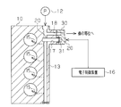
- FIG. 1 is a schematic diagram showing a schematic configuration of an internal combustion engine to which an oil jet valve mounting structure according to an embodiment of the present invention is applied.
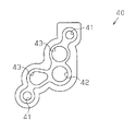
- the top view of the sealing member of FIG. The fragmentary sectional view which shows the relationship between the outer surface of the oil jet valve
- (A) And (b) is a fragmentary sectional view of an oil jet valve periphery in an attachment process.
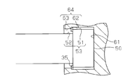
- the fragmentary sectional view which shows the relationship between the outer surface of the oil jet valve of a modification, and the inner surface of an attachment recessed part.
- the internal combustion engine 10 is provided with an oil pan 11 that stores oil and an oil pump 12 that pumps oil in the oil pan 11.
- An oil jet passage 13 is formed in the internal combustion engine 10.
- the oil jet passage 13 is supplied with oil pumped from the oil pump 12.
- an oil jet 15 for injecting and spraying oil toward the piston 14 is attached inside the internal combustion engine 10.
- the oil jet 15 is connected to the oil jet passage 13.
- the internal combustion engine 10 is provided with an oil jet valve 20 (specifically, a sleeve in which a valve body is provided so as to be reciprocally movable).
- an oil jet valve 20 (specifically, a sleeve in which a valve body is provided so as to be reciprocally movable).
- the oil jet valve 20 is opened, supply of oil to the oil jet 15 through the oil jet passage 13 is allowed, and oil is injected from the oil jet 15.
- the oil jet valve 20 is closed, the oil supply to the oil jet 15 through the oil jet passage 13 is stopped, and the oil injection from the oil jet 15 is also stopped.
- the internal combustion engine 10 includes an electronic control device 16 composed of, for example, a microcomputer as a peripheral device.
- the electronic control device 16 takes in detection signals of various sensors for detecting the operating state of the internal combustion engine 10, performs various calculations based on the detection signals, and controls the operation of the oil jet valve 20 based on the calculation results. Various controls related to engine operation are executed.
- a bracket 30 used for mounting the oil jet valve 20 is fixed to the internal combustion engine 10.
- the oil jet valve 20 is attached to the internal combustion engine 10 together with the bracket 30 while being locked to the bracket 30.
- an insertion hole 17 having a shape that opens to a surface facing the bracket 30 and extends to the oil jet passage 13 is formed.
- a mounting recess 31 is formed in the bracket 30 so as to open on the surface facing the internal combustion engine 10.
- the oil jet valve 20 has a first end and a second end, the first end is inserted and locked into the mounting recess 31 of the bracket 30, and the second end is an internal combustion engine. It is attached to the internal combustion engine 10 while being inserted into the 10 insertion holes 17.
- the bracket 30 is fastened and fixed to the internal combustion engine 10 through bolt fastening in a state where the seal member 40 is sandwiched between the internal combustion engine 10 and the bracket 30.
- the seal member 40 includes an insertion hole 41 through which a fixing bolt is inserted and an insertion hole 42 through which the oil jet valve 20 is inserted. Oil leakage from between the internal combustion engine 10 and the bracket 30 is suppressed by the seal member 40.
- the internal combustion engine 10 (FIG. 3) and the bracket 30 are connected to the interior of the internal combustion engine 10 and the interior of the bracket 30 in addition to the passage (insertion hole 17 and mounting recess 31) in which the oil jet valve 20 is disposed.
- a communicating passage for example, the passage 18 in FIG. 2 is formed. Therefore, a through hole 43 through which these passages pass is also formed in the seal member 40 (FIG. 4).
- the formation angle of the insertion hole 17 in the internal combustion engine 10 and the oil jet in the bracket 30 are determined.
- the relative position between the internal combustion engine 10 and the bracket 30 is determined by the relationship with the fixed angle of the valve 20. Therefore, a deviation in the formation angle of the insertion hole 17 due to manufacturing tolerances or a deviation in the fixing angle when the oil jet valve 20 is fixed to the bracket 30 causes a deviation in the relative position between the internal combustion engine 10 and the bracket 30. End up.
- the following structure is adopted as the structure for mounting the oil jet valve 20 to the bracket 30.
- the oil jet valve 20 is formed to have a circular cross section in a direction perpendicular to the insertion direction L of the valve 20 into the mounting recess 31.
- a flange 21 is formed on the outer surface of the oil jet valve 20 so as to protrude in an annular shape over the entire circumference.
- the protruding end of the flange 21 is an insertion portion of the oil jet valve 20 that is inserted into the mounting recess 31. Further, the protruding end of the flange 21 corresponds to the large width portion of the oil jet valve 20.
- the oil jet valve 20 has a larger width than the width of the portion of the oil jet valve 20 closer to the internal combustion engine 10 than the protruding end in the direction perpendicular to the insertion direction L to the mounting recess 31.
- the jet valve 20 has a width (length in the vertical direction in FIG. 3).
- the protruding end of the flange 21 corresponds to a large diameter portion of the oil jet valve 20 having a large outer diameter.
- the small diameter portion 24 corresponds to a small width portion having a small width of the oil jet valve 20 in a direction perpendicular to the insertion direction L to the mounting recess 31.
- the mounting recess 31 of the bracket 30 is formed to have a circular cross section in a direction perpendicular to the insertion direction L of the oil jet valve 20 into the mounting recess 31.
- a groove 32 extending in an annular shape is formed on the inner surface of the mounting recess 31 over the entire circumference of the oil jet valve 20.
- the width of the mounting recess 31 is larger in the direction perpendicular to the insertion direction L than the mounting recess 31 closer to the internal combustion engine 10 than the groove 32. Yes.
- the bottom of the groove 32 corresponds to a large diameter portion of the mounting recess 31 having a large inner diameter.
- the small diameter portion 36 corresponds to a small width portion having a small width of the mounting recess 31 in a direction perpendicular to the insertion direction L.
- a snap ring 35 is fitted in the groove 32 of the mounting recess 31.
- the snap ring 35 has one surface facing the step surface 22 of the first step portion 23 of the oil jet valve 20 and the other surface facing the step surface 33 of the second step portion 34 of the mounting recess 31.
- the first step portion 23 and the second step portion 34 are disposed between the first step portion 23 and the second step portion 34.
- the outer radius D2 of the protruding end of the flange 21 of the oil jet valve 20 is smaller than the inner radius D1 of the small diameter portion 36 of the mounting recess 31. Further, the outer radius D2 of the protruding end of the flange 21 is smaller than the inner radius D3 of the portion (facing portion 37) where the protruding end of the flange 21 faces on the inner surface of the mounting recess 31. Further, the outer radius D4 of the portion (right side portion in FIG. 5) that is farther from the internal combustion engine 10 than the flange 21 of the oil jet valve 20 is larger than the inner radius D5 of the inner surface of the mounting recess 31 that faces the portion. Is also getting smaller. In FIG. 5, for the sake of easy understanding, the difference between the outer radius D2 and the inner radius D3 and the difference between the outer radius D4 and the inner radius D5 are exaggerated. However, the actual difference is larger than this. small.
- the outer radius D2 (see FIG. 5) of the flange 21 protruding end on the outer surface of the oil jet valve 20 is equal to the small-diameter portion 36 on the inner surface of the mounting recess 31 of the bracket 30. It is smaller than the inner radius D1 (see FIG. 5). For this reason, when the oil jet valve 20 is attached to the bracket 30, the first end of the oil jet valve 20 is inserted into the mounting recess 31 of the bracket 30 as indicated by the white arrow in FIG. Can do.
- the section perpendicular to the insertion direction L of the oil jet valve 20 into the mounting recess 31 is formed in a circular shape, and the section of the mounting recess 31 perpendicular to the insertion direction L is formed in a circular shape.
- the operation of positioning the oil jet valve 20 to the bracket 30 can be performed through a simple operation such that an outer surface having a circular cross section is inserted into a recess extending in a circular cross section.
- the snap ring 35 is allowed to pass through the gap in a contracted state, and the step surface 22 (specifically, the first step portion 23 of the oil jet valve 20). Can be moved to a position where it abuts against the side surface of the flange 21. Then, by expanding the snap ring 35 at that position, the snap ring 35 can be fitted into the groove 32 of the mounting recess 31.
- the snap ring 35 is in a state in which movement in the insertion direction L is restricted through engagement with the inner surface of the groove 32 of the mounting recess 31, and the first step portion 23 and the mounting recess 31 on the outer surface of the oil jet valve 20. It is in a state of being sandwiched between the second stepped portion 34 on the inner surface. Therefore, when the step surface 22 of the first step portion 23 of the oil jet valve 20 abuts on the snap ring 35, the escape of the oil jet valve 20 from the mounting recess 31 is restricted. In this way, the first end of the oil jet valve 20 is supported by the snap ring 35 in a state in which it cannot escape from the mounting recess 31 of the bracket 30.
- the oil jet valve 20 is allowed to be inserted into the insertion hole 17 of the internal combustion engine 10 and the tip of the oil jet valve 20 is allowed to swing. Can be done. Therefore, even when the formation angle of the insertion hole 17 in the internal combustion engine 10 is deviated from a desired angle, the oil jet valve 20 is inserted into the insertion hole 17 in a state in which the oil jet valve 20 is inclined in accordance with such deviation. Will come to be.
- the bracket 30 is attached to the internal combustion engine 10 so that the parallelism of the mating surfaces of the internal combustion engine 10 and the bracket 30 is not hindered by contact between the outer surface of the oil jet valve 20 and the inner surface of the insertion hole 17. be able to. Therefore, the surface pressure of the contact portion with the sealing member 40 disposed between the mating surfaces of the internal combustion engine 10 and the bracket 30 can be sufficiently increased, and oil leakage from these mating surfaces is preferable. Can be suppressed.
- a cross section perpendicular to the insertion direction L of the oil jet valve 20 into the mounting recess 31 was formed in a circular shape, and a cross section of the mounting recess 31 perpendicular to the insertion direction L was formed in a circular shape. Therefore, the operation for positioning the oil jet valve 20 to the bracket 30 can be performed through a simple operation.
- a caulking member that is locked to the groove 32 of the mounting recess 31 through caulking may be provided.
- the caulking member can be arranged as follows. First, the caulking member is moved through the gap between the outer surface of the oil jet valve 20 and the inner surface of the mounting recess 31 to a position where it contacts the step surface 22 of the first step portion 23. At that position, the caulking member is plastically deformed by caulking, and the outer edge of the caulking member is engaged with the groove 32 of the mounting recess 31. In such an attachment structure, the caulking member corresponds to the locking member.
- the flange 21 is formed on the outer surface of the oil jet valve 20 and the groove 32 is formed on the inner surface of the mounting recess 31.
- a step-shaped first portion comprising a large-diameter portion 51 having a large outer diameter and a small-diameter portion 52 having a small outer diameter on the outer surface of the oil jet valve 50.
- One step portion 53 may be provided.
- a step-shaped second step portion 64 including a large-diameter portion 62 having a large inner diameter and a small-diameter portion 63 having a small inner diameter may be provided on the inner surface of the mounting recess 61.
- the outer diameter of the large diameter portion 51 of the first stepped portion 53 may be made smaller than the inner diameter of the small diameter portion 63 of the second stepped portion 64. Even with such a mounting structure, it is possible to obtain operational effects according to the above-described embodiment.
- Non-circular cross-section such as making the outer shape of the oil jet valve perpendicular to the direction of insertion into the mounting recess of the oil jet valve or the inner shape of the mounting recess into a polygonal cross section or an elliptical cross section It can be shaped.
- Such a shape is arbitrary as long as the first end of the oil jet valve can be inserted into the mounting recess of the bracket and the second end of the oil jet valve can be inserted into the insertion hole of the internal combustion engine.
- the shape can be adopted.
- the oil jet valve and bracket may be formed in the following shape.
- a step-shaped first step portion is formed in the oil jet valve.
- the first step portion is an insertion portion of the oil jet valve to be inserted into the mounting recess, and is the same as the wide portion having a large oil jet valve width in a direction perpendicular to the insertion direction into the mounting recess. And a small width portion formed closer to the internal combustion engine than the large width portion and having a small oil jet valve width.
- a step-shaped second step portion is formed in the mounting recess of the bracket.
- the second stepped portion has a large width having a large mounting recess width in a direction perpendicular to the insertion direction, and a smaller mounting recess width formed closer to the internal combustion engine than the large width portion. And a small width portion. And while making the width
Landscapes
- Engineering & Computer Science (AREA)
- General Engineering & Computer Science (AREA)
- Mechanical Engineering (AREA)
- Chemical & Material Sciences (AREA)
- Combustion & Propulsion (AREA)
- Lubrication Of Internal Combustion Engines (AREA)
- Fuel-Injection Apparatus (AREA)
- Cylinder Crankcases Of Internal Combustion Engines (AREA)
Abstract
オイルジェットバルブの取付構造は、内燃機関にシール部材を介して固定されるブラケットと、ブラケットの内部で延びる取付凹部と、内燃機関の内部で延びる挿入孔と、オイルジェットバルブと、オイルジェットバルブに形成される第1段差部と、取付凹部に形成される第2段差部と、第1段差部と第2段差部との間に配設される係止部材とを含んでいる。オイルジェットバルブは第1端と第2端とを有しており、第1端が取付凹部に挿入されるとともに第2端が挿入孔に挿入される。第1段差部は幅大部と幅小部とからなる。第2段差部は幅大部と幅小部とからなる。第1段差部の幅大部の幅が第2段差部の幅小部の幅よりも小さい。第1段差部の幅大部の幅が取付凹部の内面における第1段差部の幅大部に対向する部分の幅よりも小さい。
Description
本発明は、オイルジェットへのオイル供給量を制御するオイルジェットバルブを内燃機関に取り付ける取付構造に関する。
内燃機関のピストンにオイルを噴射するオイルジェットが知られている(特許文献1参照)。
特許文献1に記載の内燃機関は、オイルが供給されるオイルジェット通路と、オイルジェット通路に接続されたオイルジェットと、オイルジェット通路からオイルジェットへのオイル供給量を調節するためのオイルジェットバルブとを備えている。また上記内燃機関には内燃機関の外部と上記オイルジェット通路とを連通する挿入孔が形成されており、この挿入孔にはオイルジェットバルブが挿入されて固定されている。さらにオイルジェットバルブの外面には外方に向けて突出する形状のフランジが形成されており、このフランジと内燃機関の外面との間にシール部材が挟持されている。このシール部材により、内燃機関の挿入孔とオイルジェットバルブとの間隙を通じた機関外部へのオイル漏れが抑えられる。
特許文献1に記載の内燃機関は、オイルが供給されるオイルジェット通路と、オイルジェット通路に接続されたオイルジェットと、オイルジェット通路からオイルジェットへのオイル供給量を調節するためのオイルジェットバルブとを備えている。また上記内燃機関には内燃機関の外部と上記オイルジェット通路とを連通する挿入孔が形成されており、この挿入孔にはオイルジェットバルブが挿入されて固定されている。さらにオイルジェットバルブの外面には外方に向けて突出する形状のフランジが形成されており、このフランジと内燃機関の外面との間にシール部材が挟持されている。このシール部材により、内燃機関の挿入孔とオイルジェットバルブとの間隙を通じた機関外部へのオイル漏れが抑えられる。
上述したオイルジェットバルブの取付構造では、内燃機関における挿入孔の形成角度がずれたり、オイルジェットバルブの固定に際してその固定角度がずれたりした場合に、同バルブのフランジと内燃機関の外面(詳しくは、挿入孔の周縁)との対向面の平行度が低くなってしまう。そして、この場合にはフランジや内燃機関の外面とシール部材との接触部分の面圧を十分に高くすることができなくなって、同シール部材によるシール性能の低下を招くおそれがある。
本発明の目的は、オイルジェットバルブの取付部分におけるオイル漏れを好適に抑えることのできるオイルジェットバルブの取付構造を提供することにある。
上記目的を達成するため、本発明の一態様にかかるオイルジェットバルブの取付構造は、内燃機関にシール部材を介して固定されるブラケットと、前記ブラケットの内部で延びるとともに前記内燃機関と対向する対向面で開口する取付凹部と、前記内燃機関の内部で延びるとともに前記ブラケットと対向する対向面で開口する挿入孔と、第1端と第2端とを有しており、前記第1端が前記取付凹部に挿入されるとともに前記第2端が前記挿入孔に挿入された状態で前記内燃機関に取付けられるオイルジェットバルブと、前記オイルジェットバルブに形成される段差形状の第1段差部であって、前記取付凹部への挿入方向に対し垂直な方向において大きい前記オイルジェットバルブの幅を有しているとともに前記取付凹部へ挿入される前記オイルジェットバルブの挿入部分である幅大部と同幅大部よりも前記内燃機関寄りに形成されて前記垂直な方向において小さい前記オイルジェットバルブの幅を有している幅小部とからなる前記第1段差部と、前記取付凹部に形成される段差形状の第2段差部であって、前記垂直な方向において大きい前記取付凹部の幅を有している幅大部と同幅大部よりも前記内燃機関寄りに形成されて前記垂直な方向において小さい前記取付凹部の幅を有している幅小部とからなる前記第2段差部と、前記第1段差部と前記第2段差部との間に挟まれる位置に配設される係止部材と、を含んでいる。前記第1段差部の幅大部の幅が前記第2段差部の幅小部の幅よりも小さい。前記第1段差部の幅大部の幅が前記取付凹部の内面における前記第1段差部の幅大部に対向する部分の幅よりも小さい。
以下、オイルジェットバルブの取付構造の一実施形態について説明する。
図1または図2に示すように、内燃機関10には、オイルを貯留するオイルパン11と、オイルパン11内のオイルを圧送するオイルポンプ12とが設けられている。また、内燃機関10の内部にはオイルジェット通路13が形成されている。このオイルジェット通路13にはオイルポンプ12から圧送されたオイルが供給される。さらに、内燃機関10の内部にはピストン14に向けてオイルを噴射して吹き付けるオイルジェット15が取付られている。オイルジェット15は、オイルジェット通路13に接続されている。
図1または図2に示すように、内燃機関10には、オイルを貯留するオイルパン11と、オイルパン11内のオイルを圧送するオイルポンプ12とが設けられている。また、内燃機関10の内部にはオイルジェット通路13が形成されている。このオイルジェット通路13にはオイルポンプ12から圧送されたオイルが供給される。さらに、内燃機関10の内部にはピストン14に向けてオイルを噴射して吹き付けるオイルジェット15が取付られている。オイルジェット15は、オイルジェット通路13に接続されている。
内燃機関10にはオイルジェットバルブ20(詳しくは、内部に弁体が往復移動可能に設けられたスリーブ)が取り付けられている。このオイルジェットバルブ20の開弁時には、オイルジェット通路13を通じたオイルジェット15へのオイルの供給が許容されて、同オイルジェット15からオイルが噴射される。一方、オイルジェットバルブ20の閉弁時には、オイルジェット通路13を通じたオイルジェット15へのオイル供給が停止されて、同オイルジェット15からのオイル噴射も停止される。
内燃機関10は、その周辺機器として、例えばマイクロコンピュータなどからなる電子制御装置16を備えている。電子制御装置16は、内燃機関10の運転状態を検出するための各種センサの検出信号を取り込むとともに、それら検出信号に基づき各種の演算を行い、その演算結果に基づいてオイルジェットバルブ20の作動制御など、機関運転にかかる各種制御を実行する。
次に、オイルジェットバルブ20の取付構造について説明する。
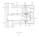
図2または図3に示すように、内燃機関10にはオイルジェットバルブ20の取付けに用いられるブラケット30が固定されている。オイルジェットバルブ20は、ブラケット30に係止された状態で、同ブラケット30ともども内燃機関10に取付けられる。内燃機関10の内部には、上記ブラケット30と対向する面において開口するとともに前記オイルジェット通路13まで延びる形状の挿入孔17が形成されている。また、ブラケット30の内部には、上記内燃機関10と対向する面において開口する形状の取付凹部31が形成されている。そして、上記オイルジェットバルブ20は第1端と第2端とを有しており、第1端がブラケット30の取付凹部31に挿入および係止された状態であり、且つ第2端が内燃機関10の挿入孔17に挿入された状態で内燃機関10に取付けられる。
図2または図3に示すように、内燃機関10にはオイルジェットバルブ20の取付けに用いられるブラケット30が固定されている。オイルジェットバルブ20は、ブラケット30に係止された状態で、同ブラケット30ともども内燃機関10に取付けられる。内燃機関10の内部には、上記ブラケット30と対向する面において開口するとともに前記オイルジェット通路13まで延びる形状の挿入孔17が形成されている。また、ブラケット30の内部には、上記内燃機関10と対向する面において開口する形状の取付凹部31が形成されている。そして、上記オイルジェットバルブ20は第1端と第2端とを有しており、第1端がブラケット30の取付凹部31に挿入および係止された状態であり、且つ第2端が内燃機関10の挿入孔17に挿入された状態で内燃機関10に取付けられる。
本実施形態では、内燃機関10とブラケット30との間にシール部材40を挟んだ状態でのボルト締結を通じて、同内燃機関10にブラケット30が締結固定されている。図4に示すように、シール部材40は、固定用のボルトを挿通する挿通孔41とオイルジェットバルブ20が挿通される挿通孔42とを備えている。このシール部材40によって、内燃機関10とブラケット30との間からのオイル漏れが抑えられている。ちなみに、内燃機関10(図3)およびブラケット30には、オイルジェットバルブ20を配設する通路(挿入孔17および取付凹部31)の他にも、内燃機関10の内部とブラケット30の内部とを連通する通路(例えば、図2における通路18)が形成されている。そのため、シール部材40(図4)には、それら通路が通過する貫通孔43も形成されている。
ここで、上述のようにオイルジェットバルブ20を取付ける場合に、仮に圧入固定やボルト締結による固定などによってオイルジェットバルブ20をブラケット30に強固に固定すると、以下のような不都合が生じるおそれがある。
この場合には、内燃機関10へのブラケット30の固定に際してオイルジェットバルブ20が内燃機関10の挿入孔17に挿入されるときに、内燃機関10における挿入孔17の形成角度とブラケット30におけるオイルジェットバルブ20の固定角度との関係によって内燃機関10とブラケット30との相対位置が定まるようになる。そのため、製造公差などによる挿入孔17の形成角度のずれや、オイルジェットバルブ20のブラケット30への固定時における固定角度のずれが、内燃機関10とブラケット30との相対位置にずれを生じさせてしまう。そして、こうした相対位置のずれは内燃機関10とブラケット30との合わせ面の平行度を低下させるために、内燃機関10やブラケット30とシール部材40との接触部分の面圧を十分に高くすることができなくなって、シール部材40によるシール性能を低下させるおそれがある。
この点をふまえて本実施形態では、オイルジェットバルブ20のブラケット30への取付構造として以下のような構造を採用している。
図3または図5に示すように、オイルジェットバルブ20は、同バルブ20の前記取付凹部31への挿入方向Lに垂直な方向において円形状の断面を有するように形成されている。またオイルジェットバルブ20の外面には、その周囲全周にわたって円環形状で突出するフランジ21が形成されている。これにより、オイルジェットバルブ20の外面には、フランジ21の突端と、同フランジ21よりも上記内燃機関10寄りの部分(小径部24)と、それらを繋ぐ上記フランジ21の側面(段差面22)とによって段差形状の第1段差部23が形成されている。なお本実施形態では、フランジ21の突端が前記取付凹部31へ挿入されるオイルジェットバルブ20の挿入部分である。また、フランジ21の突端はオイルジェットバルブ20の幅大部に相当する。オイルジェットバルブ20の幅大部は、上記取付凹部31への挿入方向Lに対して垂直な方向において、前記突端よりも内燃機関10寄りのオイルジェットバルブ20の部分の幅と比較して大きいオイルジェットバルブ20の幅(図3の上下方向の長さ)を有している。フランジ21の突端は、大きい外径を有しているオイルジェットバルブ20の大径部に相当する。また、上記小径部24が、上記取付凹部31への挿入方向Lに対して垂直な方向において小さいオイルジェットバルブ20の幅を有している幅小部に相当する。
図3または図5に示すように、オイルジェットバルブ20は、同バルブ20の前記取付凹部31への挿入方向Lに垂直な方向において円形状の断面を有するように形成されている。またオイルジェットバルブ20の外面には、その周囲全周にわたって円環形状で突出するフランジ21が形成されている。これにより、オイルジェットバルブ20の外面には、フランジ21の突端と、同フランジ21よりも上記内燃機関10寄りの部分(小径部24)と、それらを繋ぐ上記フランジ21の側面(段差面22)とによって段差形状の第1段差部23が形成されている。なお本実施形態では、フランジ21の突端が前記取付凹部31へ挿入されるオイルジェットバルブ20の挿入部分である。また、フランジ21の突端はオイルジェットバルブ20の幅大部に相当する。オイルジェットバルブ20の幅大部は、上記取付凹部31への挿入方向Lに対して垂直な方向において、前記突端よりも内燃機関10寄りのオイルジェットバルブ20の部分の幅と比較して大きいオイルジェットバルブ20の幅(図3の上下方向の長さ)を有している。フランジ21の突端は、大きい外径を有しているオイルジェットバルブ20の大径部に相当する。また、上記小径部24が、上記取付凹部31への挿入方向Lに対して垂直な方向において小さいオイルジェットバルブ20の幅を有している幅小部に相当する。
ブラケット30の取付凹部31は、オイルジェットバルブ20の同取付凹部31への挿入方向Lに垂直な方向において円形状の断面を有するように形成されている。また取付凹部31の内面には、上記オイルジェットバルブ20の周囲全周にわたって円環形状で延びる溝32が形成されている。これにより、取付凹部31の内面には、溝32の底と、取付凹部31の内面における上記溝32よりも内燃機関10寄りの部分(小径部36)と、それらを繋ぐ上記溝32の側面(段差面33)とによって段差形状の第2段差部34が形成されている。なお本実施形態では、溝32の底が取付凹部31の幅大部に相当する。取付凹部31の幅大部は、前記挿入方向Lに対して垂直な方向において、前記溝32よりも内燃機関10寄りの取付凹部31の部分と比較して大きい取付凹部31の幅を有している。溝32の底は、大きい内径を有している取付凹部31の大径部に相当する。また、小径部36が、前記挿入方向Lに対して垂直な方向において小さい取付凹部31の幅を有している幅小部に相当する。
上記取付凹部31の溝32にはスナップリング35が嵌め込まれている。スナップリング35は、一方の面がオイルジェットバルブ20の第1段差部23の段差面22に対向するとともに他方の面が取付凹部31の第2段差部34の段差面33に対向した状態で、それら第1段差部23および第2段差部34の間に挟まれる位置に配設されている。
図5に示すように、本実施形態では、取付凹部31の小径部36の内半径D1と比較して、オイルジェットバルブ20のフランジ21の突端の外半径D2が小さくなっている。また、上記フランジ21の突端の外半径D2が、取付凹部31の内面における上記フランジ21の突端が対向する部分(対向部37)の内半径D3よりも小さくなっている。さらに、オイルジェットバルブ20のフランジ21よりも上記内燃機関10から離間している部分(図5における右側の部分)の外半径D4が、同部分に対向する取付凹部31の内面の内半径D5よりも小さくなっている。なお図5では、理解を容易にするために上記外半径D2と内半径D3との差や外半径D4と内半径D5との差を誇張して示しているが、実際の差はこれよりも小さい。
以下、こうしたオイルジェットバルブ20の取付構造を採用することによる作用効果について説明する。
先ず、本実施形態では、図6(a)に示すように、オイルジェットバルブ20の外面におけるフランジ21突端の外半径D2(図5参照)が、ブラケット30の取付凹部31内面における小径部36の内半径D1(図5参照)よりも小さい。そのため、図6(a)中に白抜きの矢印で示すように、ブラケット30にオイルジェットバルブ20を取付ける際に、同オイルジェットバルブ20の第1端をブラケット30の取付凹部31に挿入することができる。また本実施形態では、オイルジェットバルブ20の前記取付凹部31への挿入方向Lに垂直な断面が円形状に形成されており、取付凹部31の上記挿入方向Lに垂直な断面が円形状に形成されている。そのため、オイルジェットバルブ20のブラケット30への取付けを、外面が断面円形状のものを断面円形状で延びる凹部に挿入するといったように、その位置決めにかかる作業が簡素な作業を通じて行うことができる。
先ず、本実施形態では、図6(a)に示すように、オイルジェットバルブ20の外面におけるフランジ21突端の外半径D2(図5参照)が、ブラケット30の取付凹部31内面における小径部36の内半径D1(図5参照)よりも小さい。そのため、図6(a)中に白抜きの矢印で示すように、ブラケット30にオイルジェットバルブ20を取付ける際に、同オイルジェットバルブ20の第1端をブラケット30の取付凹部31に挿入することができる。また本実施形態では、オイルジェットバルブ20の前記取付凹部31への挿入方向Lに垂直な断面が円形状に形成されており、取付凹部31の上記挿入方向Lに垂直な断面が円形状に形成されている。そのため、オイルジェットバルブ20のブラケット30への取付けを、外面が断面円形状のものを断面円形状で延びる凹部に挿入するといったように、その位置決めにかかる作業が簡素な作業を通じて行うことができる。
しかも、図6(b)に示すように、オイルジェットバルブ20の第1端を取付凹部31に挿入したときに、同オイルジェットバルブ20外面の小径部24と取付凹部31内面の小径部36との間に間隙が形成される。そのため図6(b)に白抜きの矢印で示すように、スナップリング35を、縮めた状態で上記間隙を通過させて、オイルジェットバルブ20の第1段差部23の段差面22(具体的には、フランジ21の側面)に突き当たる位置まで移動させることができる。そして、その位置でスナップリング35を拡げることにより、同スナップリング35を取付凹部31の溝32に嵌め込むことができる。
これによりスナップリング35は、取付凹部31の溝32内面との係合を通じて上記挿入方向Lへの移動が規制された状態になるとともに、オイルジェットバルブ20外面の第1段差部23と取付凹部31内面の第2段差部34との間に挟まれた状態になる。そのため、このスナップリング35にオイルジェットバルブ20の第1段差部23の段差面22が当接することにより、同オイルジェットバルブ20の上記取付凹部31からの脱出が規制される。このようにスナップリング35によって、オイルジェットバルブ20の第1端がブラケット30の取付凹部31に脱出不能な状態で支持されるようになる。
さらに本実施形態では、オイルジェットバルブ20をブラケット30に取付けた状態でも、オイルジェットバルブ20と取付凹部31との間に間隙(いわゆるガタ)が形成される。また、オイルジェットバルブ20のフランジ21の側面(段差面22)と取付凹部31内部に固定されたスナップリング35との係合を通じて、オイルジェットバルブ20の第1端が取付凹部31内に係止されている。そのため、オイルジェットバルブ20と取付凹部31との間隙の分だけ同オイルジェットバルブ20端部は取付凹部31の内部で移動可能になっており、その移動を通じて、図6(b)中に黒塗りの矢印で示すように、オイルジェットバルブ20の先端が揺動可能になっている。
そのため、内燃機関10(図3)にブラケット30を固定する際に、内燃機関10の挿入孔17へのオイルジェットバルブ20の挿入を、同オイルジェットバルブ20の先端の揺動が許容された状態で行うことができる。したがって、内燃機関10における挿入孔17の形成角度が所望の角度からずれている場合であっても、そうしたずれに合わせてオイルジェットバルブ20が傾いた状態で挿入孔17にオイルジェットバルブ20が挿入されるようになる。これにより、オイルジェットバルブ20の外面と挿入孔17の内面との接触によって妨げられることなく、内燃機関10とブラケット30との合わせ面の平行度が高くなるように内燃機関10にブラケット30を取り付けることができる。そのため、内燃機関10およびブラケット30の合わせ面と同合わせ面の間に配設されるシール部材40との接触部分の面圧を十分に高くすることができ、それら合わせ面からのオイル漏れを好適に抑えることができる。
以上説明したように、本実施形態によれば、以下に記載する利点が得られるようになる。
(1)内燃機関10およびブラケット30の合わせ面からのオイル漏れを好適に抑えることができる。
(1)内燃機関10およびブラケット30の合わせ面からのオイル漏れを好適に抑えることができる。
(2)スナップリング35を、縮めた状態でオイルジェットバルブ20の外面と取付凹部31の内面との間隙を通過させて、同オイルジェットバルブ20の第1段差部23の段差面22に突き当たる位置まで移動させることができる。そして、その位置でスナップリング35を拡げることにより、同スナップリング35を第1段差部23と第2段差部34との間に挟まれる位置に配設することができる。
(3)オイルジェットバルブ20の前記取付凹部31への挿入方向Lに垂直な断面を円形状に形成し、取付凹部31の上記挿入方向Lに垂直な断面を円形状に形成した。そのため、オイルジェットバルブ20のブラケット30への取付けを、その位置決めにかかる作業が簡素な作業を通じて行うことができる。
なお、上記実施形態は、以下のように変更して実施してもよい。
・スナップリング35に代えて、かしめ加工を通じて取付凹部31の溝32に係止されるかしめ部材を設けるようにしてもよい。かしめ部材は、次のようにして配設することができる。先ず、オイルジェットバルブ20の外面と取付凹部31の内面との間隙を通じてかしめ部材を第1段差部23の段差面22に突き当たる位置まで移動させる。そして、その位置で、かしめ加工によってかしめ部材を塑性変形させて、同かしめ部材の外縁を取付凹部31の溝32に係合させる。なお、こうした取付構造では、かしめ部材が係止部材に相当する。
・スナップリング35に代えて、かしめ加工を通じて取付凹部31の溝32に係止されるかしめ部材を設けるようにしてもよい。かしめ部材は、次のようにして配設することができる。先ず、オイルジェットバルブ20の外面と取付凹部31の内面との間隙を通じてかしめ部材を第1段差部23の段差面22に突き当たる位置まで移動させる。そして、その位置で、かしめ加工によってかしめ部材を塑性変形させて、同かしめ部材の外縁を取付凹部31の溝32に係合させる。なお、こうした取付構造では、かしめ部材が係止部材に相当する。
・上記実施形態では、オイルジェットバルブ20の外面にフランジ21を形成するとともに、取付凹部31の内面に溝32を形成した。これに代えて、図7に示すように、オイルジェットバルブ50の外面に大きい外径を有している大径部51と小さい外径を有している小径部52とからなる段差形状の第1段差部53を設けてもよい。さらに、取付凹部61の内面に大きい内径を有している大径部62と小さい内径を有している小径部63とからなる段差形状の第2段差部64を設けてもよい。この場合、第1段差部53の大径部51の外径を第2段差部64の小径部63の内径よりも小さくすればよい。こうした取付構造によっても、上記実施形態に準じた作用効果を得ることができる。
・オイルジェットバルブの取付凹部への挿入方向に対して垂直な方向における同オイルジェットバルブの外面形状や取付凹部の内面形状を、断面多角形状にしたり断面楕円形状にしたりするなど、円形以外の断面形状にすることができる。そうした形状としては、オイルジェットバルブの第1端をブラケットの取付凹部に挿入可能な形状であって、同オイルジェットバルブの第2端を内燃機関の挿通孔に挿入可能な形状であれば、任意の形状を採用することができる。
この場合には、オイルジェットバルブやブラケットを次のような形状に形成すればよい。オイルジェットバルブに段差形状の第1段差部を形成する。第1段差部は、取付凹部へ挿入されるオイルジェットバルブの挿入部分であるとともに取付凹部への挿入方向に対し垂直な方向において大きいオイルジェットバルブの幅を有している幅大部と、同幅大部よりも内燃機関寄りに形成されて小さいオイルジェットバルブの幅を有している幅小部と、を有するように形成される。またブラケットの取付凹部に段差形状の第2段差部を形成する。第2段差部は、上記挿入方向に対し垂直な方向において大きい取付凹部の幅を有している幅大部と、同幅大部よりも内燃機関寄りに形成されて小さい取付凹部の幅を有している幅小部と、を有するように形成される。そして、第1段差部の幅大部の幅を第2段差部の幅小部の幅よりも小さくするとともに、第1段差部の幅大部の幅を取付凹部の内面における上記第1段差部の幅大部に対向する部分の幅よりも小さくする。こうしたオイルジェットバルブの取付構造によれば、上記(1)や(2)に記載の利点に準じた利点を得ることができる。
Claims (4)
- 内燃機関にシール部材を介して固定されるブラケットと、
前記ブラケットの内部で延びるとともに前記内燃機関と対向する対向面で開口する取付凹部と、
前記内燃機関の内部で延びるとともに前記ブラケットと対向する対向面で開口する挿入孔と、
第1端と第2端とを有しており、前記第1端が前記取付凹部に挿入されるとともに前記第2端が前記挿入孔に挿入された状態で前記内燃機関に取付けられるオイルジェットバルブと、
前記オイルジェットバルブに形成される段差形状の第1段差部であって、前記取付凹部への挿入方向に対し垂直な方向において大きい前記オイルジェットバルブの幅を有しているとともに前記取付凹部へ挿入される前記オイルジェットバルブの挿入部分である幅大部と同幅大部よりも前記内燃機関寄りに形成されて前記垂直な方向において小さい前記オイルジェットバルブの幅を有している幅小部とからなる前記第1段差部と、
前記取付凹部に形成される段差形状の第2段差部であって、前記垂直な方向において大きい前記取付凹部の幅を有している幅大部と同幅大部よりも前記内燃機関寄りに形成されて前記垂直な方向において小さい前記取付凹部の幅を有している幅小部とからなる前記第2段差部と、
前記第1段差部と前記第2段差部との間に挟まれる位置に配設される係止部材と、を備え、
前記第1段差部の幅大部の幅が前記第2段差部の幅小部の幅よりも小さく、
前記第1段差部の幅大部の幅が前記取付凹部の内面における前記第1段差部の幅大部に対向する部分の幅よりも小さい、オイルジェットバルブの取付構造。 - 請求項1に記載のオイルジェットバルブの取付構造において、
前記オイルジェットバルブの外面にはその周囲全周にわたって突出するフランジが形成されており、
前記フランジの突端が前記第1段差部の幅大部であって、
前記外面における前記フランジよりも前記内燃機関寄りの部分が前記第1段差部の幅小部であり、
前記取付凹部の内面には前記オイルジェットバルブの周囲全周にわたって延びる環状の溝が形成されており、
前記溝の底が前記第2段差部の幅大部であって、
前記取付凹部の内面における前記溝よりも前記内燃機関寄りの部分が前記第2段差部の幅小部である、
オイルジェットバルブの取付構造。 - 請求項1または2に記載のオイルジェットバルブの取付構造において、
前記係止部材は、スナップリングである、
オイルジェットバルブの取付構造。 - 請求項1~3のいずれか一項に記載のオイルジェットバルブの取付構造において、
前記オイルジェットバルブは、該オイルジェットバルブの前記取付凹部への挿入方向に垂直な方向において円形状の断面を有しており、
前記第1段差部の幅大部は大きい前記オイルジェットバルブの外径を有している大径部であって、前記第1段差部の幅小部は小さい前記オイルジェットバルブの外径を有している小径部であり、
前記取付凹部は、前記オイルジェットバルブの前記取付凹部への挿入方向に垂直な方向において円形状の断面を有しており、
前記第2段差部の幅大部は大きい前記取付凹部の内径を有している大径部であって、前記第2段差部の幅小部は小さい前記取付凹部の内径を有している小径部である、
オイルジェットバルブの取付構造。
Priority Applications (3)
| Application Number | Priority Date | Filing Date | Title |
|---|---|---|---|
| CN201580004482.0A CN105917087B (zh) | 2014-01-17 | 2015-01-15 | 机油喷射阀的安装构造 |
| DE112015000423.8T DE112015000423T5 (de) | 2014-01-17 | 2015-01-15 | Struktur zum Montieren eines Ölspritzeinrichtungsventils |
| US15/110,234 US9822676B2 (en) | 2014-01-17 | 2015-01-15 | Structure for attaching oil jet valve |
Applications Claiming Priority (2)
| Application Number | Priority Date | Filing Date | Title |
|---|---|---|---|
| JP2014006515A JP6030585B2 (ja) | 2014-01-17 | 2014-01-17 | オイルジェットバルブの取付方法 |
| JP2014-006515 | 2014-01-17 |
Publications (1)
| Publication Number | Publication Date |
|---|---|
| WO2015108099A1 true WO2015108099A1 (ja) | 2015-07-23 |
Family
ID=53542985
Family Applications (1)
| Application Number | Title | Priority Date | Filing Date |
|---|---|---|---|
| PCT/JP2015/050910 Ceased WO2015108099A1 (ja) | 2014-01-17 | 2015-01-15 | オイルジェットバルブの取付構造 |
Country Status (5)
| Country | Link |
|---|---|
| US (1) | US9822676B2 (ja) |
| JP (1) | JP6030585B2 (ja) |
| CN (1) | CN105917087B (ja) |
| DE (1) | DE112015000423T5 (ja) |
| WO (1) | WO2015108099A1 (ja) |
Cited By (1)
| Publication number | Priority date | Publication date | Assignee | Title |
|---|---|---|---|---|
| EP3254764A1 (en) * | 2016-06-07 | 2017-12-13 | United Technologies Corporation | Nozzle for delivering fluid to a component |
Families Citing this family (1)
| Publication number | Priority date | Publication date | Assignee | Title |
|---|---|---|---|---|
| US10858982B2 (en) * | 2018-04-19 | 2020-12-08 | Ford Global Technologies, Llc | Piston cooling system |
Citations (8)
| Publication number | Priority date | Publication date | Assignee | Title |
|---|---|---|---|---|
| US4142282A (en) * | 1976-09-17 | 1979-03-06 | Caterpillar Tractor Co. | Method for assembling a cartridge-type valve |
| JPS60127423U (ja) * | 1984-02-07 | 1985-08-27 | トヨタ自動車株式会社 | ピストン冷却用オイルジエツトのオイル通路 |
| JPH02301648A (ja) * | 1989-05-17 | 1990-12-13 | Yamaha Motor Co Ltd | 内燃機関用ピストンの冷却機構 |
| JPH08326535A (ja) * | 1995-05-31 | 1996-12-10 | Nissan Motor Co Ltd | 内燃機関のピストン冷却装置 |
| JPH09133235A (ja) * | 1995-11-06 | 1997-05-20 | Fuji Koki:Kk | 三方口逆止弁 |
| JPH1061436A (ja) * | 1996-08-23 | 1998-03-03 | Aichi Mach Ind Co Ltd | エンジン |
| JPH11182242A (ja) * | 1997-12-19 | 1999-07-06 | Unisia Jecs Corp | リリーフ弁装置 |
| JPH11210906A (ja) * | 1998-01-20 | 1999-08-06 | Fujikoki Corp | 逆止弁 |
Family Cites Families (30)
| Publication number | Priority date | Publication date | Assignee | Title |
|---|---|---|---|---|
| US2940472A (en) * | 1957-02-25 | 1960-06-14 | Futurecraft Corp | Check valve |
| US3741342A (en) * | 1971-11-08 | 1973-06-26 | Int Harvester Co | Engine oil cooling and filtering method and apparatus |
| US4206726A (en) * | 1977-07-18 | 1980-06-10 | Caterpillar Tractor Co. | Double orifice piston cooling nozzle for reciprocating engines |
| JPS5884320U (ja) * | 1981-12-02 | 1983-06-08 | ダイハツ工業株式会社 | 内燃機関のピストン冷却用オイルジエツト圧入装置 |
| JPS59186416U (ja) * | 1983-05-28 | 1984-12-11 | トヨタ自動車株式会社 | ピストンの冷却装置 |
| JP2629936B2 (ja) * | 1989-01-31 | 1997-07-16 | スズキ株式会社 | 自動2輪車エンジンの潤滑装置 |
| JPH0810034B2 (ja) * | 1990-06-06 | 1996-01-31 | 株式会社ナブコ | 流体圧力弁の管座取付装置 |
| JP2565501Y2 (ja) * | 1991-08-30 | 1998-03-18 | いすゞ自動車株式会社 | ピストン冷却用オイルジェット装置 |
| JPH0552225U (ja) * | 1991-12-16 | 1993-07-13 | いすゞ自動車株式会社 | ピストン冷却用オイルジェット |
| JPH08158843A (ja) * | 1994-12-05 | 1996-06-18 | Suzuki Motor Corp | 潤滑油の圧力調整装置 |
| US5740777A (en) | 1995-05-16 | 1998-04-21 | Mitsubishi Jidosha Kogyo Kabushiki Kaisha | In-cylinder injection internal combustion engine |
| US5649505A (en) * | 1996-01-18 | 1997-07-22 | Cummins Engine Company, Inc. | Multiple-hole, piston cooling nozzle and assembly arrangement therefore |
| KR100215408B1 (ko) * | 1996-12-24 | 1999-08-16 | 양재신 | 윤활장치의 오일젯 결합구조 |
| JPH11210459A (ja) * | 1998-01-29 | 1999-08-03 | Unisia Jecs Corp | リリーフ弁装置 |
| EP0947285A1 (en) | 1998-03-31 | 1999-10-06 | Senior Engineering Investments AG | Automotive engine fluid spray tube apparatus and method for making same |
| JP2000337118A (ja) * | 1999-05-25 | 2000-12-05 | Honda Motor Co Ltd | 内燃機関におけるオイルポンプ取付装置 |
| JP2001004036A (ja) * | 1999-06-21 | 2001-01-09 | Ayumi Kogyo Kk | 内挿リングを有するバルブ |
| JP4394815B2 (ja) * | 2000-09-18 | 2010-01-06 | 本田技研工業株式会社 | エンジンにおけるタイミングチェーン潤滑構造 |
| FR2827009B1 (fr) | 2001-07-04 | 2003-12-12 | Bontaz Centre Sa | Gicleur de refroidissement a piston |
| JP3946005B2 (ja) * | 2001-07-17 | 2007-07-18 | 本田技研工業株式会社 | ピストン冷却用オイルジェット装置 |
| JP2003090217A (ja) * | 2001-09-17 | 2003-03-28 | Usui Internatl Ind Co Ltd | 内燃機関のピストン冷却用オイルジェットパイプ |
| EP1391229B1 (en) * | 2002-08-19 | 2006-01-25 | Perkins Engines Company Limited | Fluid filtration system with helical filter element |
| JP2007016604A (ja) * | 2005-07-05 | 2007-01-25 | Nissan Motor Co Ltd | エンジンの動弁装置 |
| JP2009293380A (ja) | 2008-06-02 | 2009-12-17 | Toyota Motor Corp | ドレン構造 |
| FR2935771B1 (fr) * | 2008-09-09 | 2010-10-08 | Bontaz Centre Sa | Dispositif de commande de l'alimentation d'un systeme avec un fluide |
| JP2010281244A (ja) * | 2009-06-03 | 2010-12-16 | Matsumoto Jukogyo Kk | オイルジェット及びその製造方法 |
| JP5265499B2 (ja) * | 2009-11-06 | 2013-08-14 | 愛三工業株式会社 | オイルジェット |
| US8511261B2 (en) * | 2010-02-23 | 2013-08-20 | Honda Motor Co., Ltd. | Piston cooling device |
| JP5783407B2 (ja) * | 2011-04-14 | 2015-09-24 | アイシン精機株式会社 | 油圧制御装置 |
| WO2014003725A1 (en) * | 2012-06-26 | 2014-01-03 | International Engine Intellectual Property Company, Llc | Selective internal distribution of engine motor oil |
-
2014
- 2014-01-17 JP JP2014006515A patent/JP6030585B2/ja active Active
-
2015
- 2015-01-15 DE DE112015000423.8T patent/DE112015000423T5/de not_active Ceased
- 2015-01-15 US US15/110,234 patent/US9822676B2/en active Active
- 2015-01-15 WO PCT/JP2015/050910 patent/WO2015108099A1/ja not_active Ceased
- 2015-01-15 CN CN201580004482.0A patent/CN105917087B/zh active Active
Patent Citations (8)
| Publication number | Priority date | Publication date | Assignee | Title |
|---|---|---|---|---|
| US4142282A (en) * | 1976-09-17 | 1979-03-06 | Caterpillar Tractor Co. | Method for assembling a cartridge-type valve |
| JPS60127423U (ja) * | 1984-02-07 | 1985-08-27 | トヨタ自動車株式会社 | ピストン冷却用オイルジエツトのオイル通路 |
| JPH02301648A (ja) * | 1989-05-17 | 1990-12-13 | Yamaha Motor Co Ltd | 内燃機関用ピストンの冷却機構 |
| JPH08326535A (ja) * | 1995-05-31 | 1996-12-10 | Nissan Motor Co Ltd | 内燃機関のピストン冷却装置 |
| JPH09133235A (ja) * | 1995-11-06 | 1997-05-20 | Fuji Koki:Kk | 三方口逆止弁 |
| JPH1061436A (ja) * | 1996-08-23 | 1998-03-03 | Aichi Mach Ind Co Ltd | エンジン |
| JPH11182242A (ja) * | 1997-12-19 | 1999-07-06 | Unisia Jecs Corp | リリーフ弁装置 |
| JPH11210906A (ja) * | 1998-01-20 | 1999-08-06 | Fujikoki Corp | 逆止弁 |
Cited By (1)
| Publication number | Priority date | Publication date | Assignee | Title |
|---|---|---|---|---|
| EP3254764A1 (en) * | 2016-06-07 | 2017-12-13 | United Technologies Corporation | Nozzle for delivering fluid to a component |
Also Published As
| Publication number | Publication date |
|---|---|
| CN105917087B (zh) | 2018-09-25 |
| JP2015135075A (ja) | 2015-07-27 |
| DE112015000423T5 (de) | 2016-10-06 |
| US9822676B2 (en) | 2017-11-21 |
| JP6030585B2 (ja) | 2016-11-24 |
| US20160326920A1 (en) | 2016-11-10 |
| CN105917087A (zh) | 2016-08-31 |
Similar Documents
| Publication | Publication Date | Title |
|---|---|---|
| US7000633B2 (en) | Flow amount control device | |
| US9347411B2 (en) | Decoupling element for a fuel injection device | |
| US9541025B2 (en) | Sealing structure | |
| KR20150069563A (ko) | 내연기관의 밸브용의 개스킷 및 내연기관용의 밸브 | |
| JP6030585B2 (ja) | オイルジェットバルブの取付方法 | |
| US9803605B2 (en) | Fluid injection assembly | |
| JP4418267B2 (ja) | チェックバルブ | |
| KR20150091164A (ko) | 내연기관용 플랩 장치 | |
| WO2017030060A1 (ja) | バルブステムシール及び密封構造 | |
| JP6036982B2 (ja) | 密封構造 | |
| JP2011196260A (ja) | 筒内噴射式燃料噴射弁への燃料供給装置 | |
| CN104769270A (zh) | 燃料喷射器 | |
| JP6892789B2 (ja) | 燃料インジェクタのためのガスケット | |
| KR102200623B1 (ko) | 유체 분사기 및 유체 분사기용 니들 | |
| JP2005530091A (ja) | 内燃機関のための燃料噴射弁 | |
| KR20130040955A (ko) | 유체 작동 기계용 면 실링 고리형 밸브 | |
| US20130284828A1 (en) | Device for injecting fuel | |
| JP2009108758A (ja) | 燃料噴射弁およびその製造方法 | |
| JP2004526895A (ja) | 内燃機関のための燃料噴射弁 | |
| JP2010216567A (ja) | バルブステムシール | |
| JP2016084711A5 (ja) | ||
| US10487731B2 (en) | Internal combustion engine | |
| CN100441917C (zh) | 一种汽车电控机械式自动变速器选档油缸 | |
| KR200419730Y1 (ko) | 자동차 엔진용 오일씰 | |
| JP5006220B2 (ja) | 燃料噴射弁 |
Legal Events
| Date | Code | Title | Description |
|---|---|---|---|
| 121 | Ep: the epo has been informed by wipo that ep was designated in this application |
Ref document number: 15737455 Country of ref document: EP Kind code of ref document: A1 |
|
| WWE | Wipo information: entry into national phase |
Ref document number: 15110234 Country of ref document: US |
|
| WWE | Wipo information: entry into national phase |
Ref document number: 112015000423 Country of ref document: DE |
|
| 122 | Ep: pct application non-entry in european phase |
Ref document number: 15737455 Country of ref document: EP Kind code of ref document: A1 |