WO2015107916A1 - エネルギー処置具 - Google Patents
エネルギー処置具 Download PDFInfo
- Publication number
- WO2015107916A1 WO2015107916A1 PCT/JP2015/050036 JP2015050036W WO2015107916A1 WO 2015107916 A1 WO2015107916 A1 WO 2015107916A1 JP 2015050036 W JP2015050036 W JP 2015050036W WO 2015107916 A1 WO2015107916 A1 WO 2015107916A1
- Authority
- WO
- WIPO (PCT)
- Prior art keywords
- jaw
- movable handle
- closed
- open
- unit
- Prior art date
- Legal status (The legal status is an assumption and is not a legal conclusion. Google has not performed a legal analysis and makes no representation as to the accuracy of the status listed.)
- Ceased
Links
Images


Classifications
-
- A—HUMAN NECESSITIES
- A61—MEDICAL OR VETERINARY SCIENCE; HYGIENE
- A61B—DIAGNOSIS; SURGERY; IDENTIFICATION
- A61B18/00—Surgical instruments, devices or methods for transferring non-mechanical forms of energy to or from the body
- A61B18/04—Surgical instruments, devices or methods for transferring non-mechanical forms of energy to or from the body by heating
- A61B18/12—Surgical instruments, devices or methods for transferring non-mechanical forms of energy to or from the body by heating by passing a current through the tissue to be heated, e.g. high-frequency current
- A61B18/14—Probes or electrodes therefor
- A61B18/1442—Probes having pivoting end effectors, e.g. forceps
-
- A—HUMAN NECESSITIES
- A61—MEDICAL OR VETERINARY SCIENCE; HYGIENE
- A61B—DIAGNOSIS; SURGERY; IDENTIFICATION
- A61B17/00—Surgical instruments, devices or methods
- A61B17/32—Surgical cutting instruments
- A61B17/320068—Surgical cutting instruments using mechanical vibrations, e.g. ultrasonic
- A61B17/320092—Surgical cutting instruments using mechanical vibrations, e.g. ultrasonic with additional movable means for clamping or cutting tissue, e.g. with a pivoting jaw
-
- A—HUMAN NECESSITIES
- A61—MEDICAL OR VETERINARY SCIENCE; HYGIENE
- A61B—DIAGNOSIS; SURGERY; IDENTIFICATION
- A61B18/00—Surgical instruments, devices or methods for transferring non-mechanical forms of energy to or from the body
- A61B18/04—Surgical instruments, devices or methods for transferring non-mechanical forms of energy to or from the body by heating
- A61B18/12—Surgical instruments, devices or methods for transferring non-mechanical forms of energy to or from the body by heating by passing a current through the tissue to be heated, e.g. high-frequency current
- A61B18/1206—Generators therefor
-
- A—HUMAN NECESSITIES
- A61—MEDICAL OR VETERINARY SCIENCE; HYGIENE
- A61B—DIAGNOSIS; SURGERY; IDENTIFICATION
- A61B18/00—Surgical instruments, devices or methods for transferring non-mechanical forms of energy to or from the body
- A61B18/04—Surgical instruments, devices or methods for transferring non-mechanical forms of energy to or from the body by heating
- A61B18/12—Surgical instruments, devices or methods for transferring non-mechanical forms of energy to or from the body by heating by passing a current through the tissue to be heated, e.g. high-frequency current
- A61B18/14—Probes or electrodes therefor
- A61B18/1442—Probes having pivoting end effectors, e.g. forceps
- A61B18/1445—Probes having pivoting end effectors, e.g. forceps at the distal end of a shaft, e.g. forceps or scissors at the end of a rigid rod
-
- A—HUMAN NECESSITIES
- A61—MEDICAL OR VETERINARY SCIENCE; HYGIENE
- A61B—DIAGNOSIS; SURGERY; IDENTIFICATION
- A61B18/00—Surgical instruments, devices or methods for transferring non-mechanical forms of energy to or from the body
- A61B18/04—Surgical instruments, devices or methods for transferring non-mechanical forms of energy to or from the body by heating
- A61B18/12—Surgical instruments, devices or methods for transferring non-mechanical forms of energy to or from the body by heating by passing a current through the tissue to be heated, e.g. high-frequency current
- A61B18/14—Probes or electrodes therefor
- A61B18/1482—Probes or electrodes therefor having a long rigid shaft for accessing the inner body transcutaneously in minimal invasive surgery, e.g. laparoscopy
-
- A—HUMAN NECESSITIES
- A61—MEDICAL OR VETERINARY SCIENCE; HYGIENE
- A61B—DIAGNOSIS; SURGERY; IDENTIFICATION
- A61B18/00—Surgical instruments, devices or methods for transferring non-mechanical forms of energy to or from the body
- A61B18/04—Surgical instruments, devices or methods for transferring non-mechanical forms of energy to or from the body by heating
- A61B18/12—Surgical instruments, devices or methods for transferring non-mechanical forms of energy to or from the body by heating by passing a current through the tissue to be heated, e.g. high-frequency current
- A61B18/14—Probes or electrodes therefor
- A61B18/1485—Probes or electrodes therefor having a short rigid shaft for accessing the inner body through natural openings
-
- A—HUMAN NECESSITIES
- A61—MEDICAL OR VETERINARY SCIENCE; HYGIENE
- A61B—DIAGNOSIS; SURGERY; IDENTIFICATION
- A61B17/00—Surgical instruments, devices or methods
- A61B17/32—Surgical cutting instruments
- A61B17/320068—Surgical cutting instruments using mechanical vibrations, e.g. ultrasonic
- A61B2017/320072—Working tips with special features, e.g. extending parts
-
- A—HUMAN NECESSITIES
- A61—MEDICAL OR VETERINARY SCIENCE; HYGIENE
- A61B—DIAGNOSIS; SURGERY; IDENTIFICATION
- A61B17/00—Surgical instruments, devices or methods
- A61B17/32—Surgical cutting instruments
- A61B17/320068—Surgical cutting instruments using mechanical vibrations, e.g. ultrasonic
- A61B2017/320088—Surgical cutting instruments using mechanical vibrations, e.g. ultrasonic with acoustic insulation, e.g. elements for damping vibrations between horn and surrounding sheath
-
- A—HUMAN NECESSITIES
- A61—MEDICAL OR VETERINARY SCIENCE; HYGIENE
- A61B—DIAGNOSIS; SURGERY; IDENTIFICATION
- A61B18/00—Surgical instruments, devices or methods for transferring non-mechanical forms of energy to or from the body
- A61B2018/00994—Surgical instruments, devices or methods for transferring non-mechanical forms of energy to or from the body combining two or more different kinds of non-mechanical energy or combining one or more non-mechanical energies with ultrasound
-
- A—HUMAN NECESSITIES
- A61—MEDICAL OR VETERINARY SCIENCE; HYGIENE
- A61B—DIAGNOSIS; SURGERY; IDENTIFICATION
- A61B18/00—Surgical instruments, devices or methods for transferring non-mechanical forms of energy to or from the body
- A61B18/04—Surgical instruments, devices or methods for transferring non-mechanical forms of energy to or from the body by heating
- A61B18/12—Surgical instruments, devices or methods for transferring non-mechanical forms of energy to or from the body by heating by passing a current through the tissue to be heated, e.g. high-frequency current
- A61B18/14—Probes or electrodes therefor
- A61B18/1442—Probes having pivoting end effectors, e.g. forceps
- A61B2018/1452—Probes having pivoting end effectors, e.g. forceps including means for cutting
-
- A—HUMAN NECESSITIES
- A61—MEDICAL OR VETERINARY SCIENCE; HYGIENE
- A61B—DIAGNOSIS; SURGERY; IDENTIFICATION
- A61B18/00—Surgical instruments, devices or methods for transferring non-mechanical forms of energy to or from the body
- A61B18/04—Surgical instruments, devices or methods for transferring non-mechanical forms of energy to or from the body by heating
- A61B18/12—Surgical instruments, devices or methods for transferring non-mechanical forms of energy to or from the body by heating by passing a current through the tissue to be heated, e.g. high-frequency current
- A61B18/14—Probes or electrodes therefor
- A61B2018/1465—Deformable electrodes
Definitions
- the present invention relates to a forceps-type energy treatment device in which a distal end portion of a jaw is opened and closed with respect to a distal end portion of a probe by opening and closing a movable handle with respect to a fixed handle.
- a general forceps-type energy treatment device has a probe and a jaw that can be opened and closed with respect to the probe.
- the tip of the jaw is closed with respect to the tip of the probe so that the tip of the jaw and the tip of the probe sandwich the treatment target such as a living tissue and grip the treatment target.
- the tip of the jaw opens with respect to the tip of the probe so that the tip of the jaw and the tip of the probe are pushed into the treatment object, for example, and the treatment object is spread and separated.
- Patent Document 1 An energy treatment instrument that performs the gripping operation and the peeling operation as described above is disclosed in Patent Document 1, for example.
- the entire jaw including the tip of the jaw is formed of a highly rigid member (for example, metal).
- a highly rigid member for example, metal
- the jaw may be gradually deformed by a reaction force from the treatment target.
- the deformed jaw has high jaw rigidity, there is a possibility that the deformed jaw does not return to the original state. As a result, there is a possibility that treatment power such as gripping force and peeling force gradually decreases.
- the present invention has been made in view of these circumstances, and an object of the present invention is to provide an energy treatment device that can prevent the treatment power from gradually decreasing even if the treatment operation is repeated.
- One aspect of the energy treatment device of the present invention includes a probe extending along a longitudinal axis, a fixed handle, and a probe attached to a distal end of the fixed handle, with the distal end portion of the probe protruding from the distal end.
- a sheath unit extending through the longitudinal axis, and a fixed side including the probe and the sheath unit for a treatment operation for treating a treatment target.
- a movable handle unit that can be opened and closed, and the movable handle unit that is openable and closable, and that the movable handle unit opens and closes with respect to the fixed side for the treatment operation.
- an accelerating portion that promotes elastic deformation of the movable handle unit in the direction of receiving the reaction force when receiving a force.
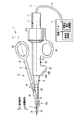
- FIG. 1 is a schematic view of a medical treatment apparatus according to the first embodiment of the present invention.
- FIG. 2 is a cross-sectional view showing the configuration of the vibrator unit.
- FIG. 3 is a side view including a partial cross section of the probe.
- FIG. 4 is a schematic cross-sectional view showing an internal configuration of the fixed handle.
- FIG. 5 is a schematic diagram illustrating an electrical connection state in the vibrator case, the cylindrical member, and the electrical connection ring.
- FIG. 6 is a schematic cross-sectional view showing a state where the probe is inserted through the sheath according to the first embodiment.
- 7 is a cross-sectional view taken along line VII-VII shown in FIG. FIG.
- FIG. 8 is a schematic cross-sectional view illustrating the configuration of the first groove defining portion and the first protrusion of the electrical contact unit according to the first embodiment.
- FIG. 9 is a schematic cross-sectional view showing the sheath and the jaw in a state where the jaw is not attached to the sheath according to the first embodiment.
- FIG. 10A is a diagram illustrating a configuration of the promotion unit according to the first embodiment.
- FIG. 10B is a diagram illustrating the action of the promotion unit in the gripping operation.
- FIG. 10C is a diagram illustrating the action of the promoting portion in the peeling operation.
- FIG. 11A is a diagram illustrating a configuration of a promotion unit according to a first modification of the first embodiment.
- FIG. 11B is a diagram illustrating a configuration of a promotion unit according to a second modification of the first embodiment.
- FIG. 12A is a diagram illustrating a configuration of a promotion unit according to the second embodiment.
- FIG. 12B is a diagram illustrating an example of a cross section of the promoting portion.
- FIG. 12C is a diagram illustrating an example of a cross section of the promoting portion.
- FIG. 12D is a diagram illustrating an example of a cross section of the promoting portion.
- FIG. 12E is a diagram illustrating an example of a cross section of the promoting portion.
- 12F is a cross-sectional view taken along line 12F-12F shown in FIG. 12A.
- FIG. 13 is a diagram illustrating a configuration of the promotion unit according to the third embodiment.
- FIG. 12A is a diagram illustrating a configuration of a promotion unit according to the second embodiment.
- FIG. 12B is a diagram illustrating an example of a cross section of the promoting
- FIG. 14 is a diagram illustrating a configuration of a promotion unit according to the fourth embodiment.
- FIG. 15A is a diagram illustrating an example of a constituent member of the promotion unit according to the fifth embodiment.
- FIG. 15B is a diagram illustrating a configuration of a promotion unit according to the fifth embodiment.
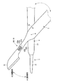
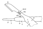
- a medical treatment apparatus 1 shown in FIG. 1 is positioned at a distal end portion of a first electrode portion 21 located at a distal end portion of a probe 3 and a jaw 52 described later.
- a treatment target such as a living tissue is sandwiched and held by the second electrode unit 53 that performs the above operation.
- the gripping is performed by closing (approaching) the second electrode portion 53 with respect to the first electrode portion 21.
- the medical treatment apparatus 1 can treat the grasped treatment target with energy such as ultrasonic waves, high frequencies, and heat.
- Such a medical treatment apparatus 1 is a grasping treatment apparatus.
- the medical treatment apparatus 1 of the present embodiment is also used as a bipolar treatment apparatus that treats with a high-frequency current using the distal end portion of the probe 3 and the jaw 52 as electrodes.
- the medical treatment apparatus 1 is also used as an ultrasonic treatment apparatus that performs treatment by ultrasonic vibration.
- the medical treatment apparatus 1 is pushed into the treatment target and peels off the treatment target by the tip portion of the probe 3 and the jaw 52. As shown in FIG. 10C, the peeling is performed by opening (separating) the second electrode portion 53 from the first electrode portion 21.
- the medical treatment apparatus 1 includes a power supply unit 7 that functions as a supply unit that supplies electric power for energy, and a treatment instrument 10 that treats a treatment target with the energy supplied from the power supply unit 7. have.
- the power supply unit 7 includes an ultrasonic control unit 8 that controls a current for ultrasonic vibration and a high-frequency current control unit 9 that controls a current for high frequency.
- the power supply unit 7 further includes a cable 6 that is electrically connected to the ultrasonic control unit 8 and the treatment instrument 10 and electrically connected to the high-frequency current control unit 9 and the treatment instrument 10.
- One end of the cable 6 is connected to the power supply unit 7, and the other end of the cable 6 is connected to a base end of a vibrator case 11 described later.
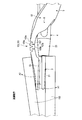
- the treatment instrument 10 includes a transducer unit 2, a probe 3, a sheath unit 4, and a movable handle unit 5.
- the transducer unit 2, the probe 3, and the sheath unit 4 are fixed sides, and the movable handle unit 5 is a movable side that is movable so as to be rotatable with respect to the fixed side.
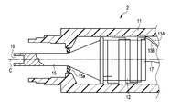
- the vibrator unit 2 As shown in FIGS. 1 and 2, the vibrator unit 2 has a vibrator case 11. As described above, the base end of the vibrator case 11 is connected to the end of the cable 6.
- the transducer unit 2 includes an ultrasonic transducer 12 that is provided inside the transducer case 11 and has a piezoelectric element that converts the current supplied from the ultrasonic control unit 8 into ultrasonic vibration. Have.
- the ultrasonic transducer 12 is connected to one end of the electric signal lines 13A and 13B.
- the electric signal lines 13 ⁇ / b> A and 13 ⁇ / b> B are provided inside the cable 6.
- the other ends of the electric signal lines 13 ⁇ / b> A and 13 ⁇ / b> B are connected to the ultrasonic control unit 8 of the power supply unit 7.
- an electric current is supplied from the ultrasonic control unit 8 to the ultrasonic transducer 12 via the electric signal lines 13 ⁇ / b> A and 13 ⁇ / b> B, ultrasonic vibration is generated in the ultrasonic transducer 12.
- the ultrasonic transducer 12 is connected to one end of the electrical signal line 17 separately from the electrical signal lines 13A and 13B.
- the electric signal line 17 is provided inside the cable 6.
- the other end of the electric signal line 17 is connected to the high frequency current control unit 9 of the power supply unit 7.
- the electric signal lines 13A, 13B, and 17 are included in the cable 6.
- the transducer unit 2 is connected to the tip of the ultrasonic transducer 12 so as to be located at the tip of the ultrasonic transducer 12, and the amplitude of the ultrasonic vibration generated by the ultrasonic transducer 12 is changed. It further has an expanding horn 15.
- the horn 15 is attached to the vibrator case 11 via an insulating member 15a.
- the horn 15 is electrically insulated from the vibrator case 11 by an insulating member 15a.
- the horn 15 has a female screw portion 16 formed at the tip of the horn 15.
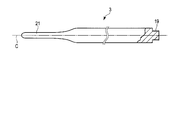
- the probe 3 extends along the longitudinal axis C.
- the probe 3 has a column shape.
- the probe 3 has a male screw portion 19 that is formed at the base end portion of the probe 3 and is screwed into the female screw portion 16 of the horn 15.
- the probe 3 is attached to the horn 15 by screwing. Thereby, the ultrasonic vibration generated by the ultrasonic vibrator 12 is transmitted to the tip of the probe 3 through the horn 15 and the probe 3. That is, the ultrasonic vibration is transmitted from the proximal end of the probe 3 to the distal end.
- the ultrasonic vibration is longitudinal vibration in which the vibration transmission direction and the vibration direction coincide with each other.
- a probe-side current path for high-frequency current is formed from the high-frequency current control unit 9 to the tip of the probe 3 through the electric signal line 17, the ultrasonic transducer 12 and the horn 15.
- the probe 3 has a first electrode portion 21 formed at the distal end portion of the probe 3. That is, the high-frequency current is transmitted along the longitudinal axis C between the high-frequency current control unit 9 and the first electrode unit 21 by the probe-side current path.
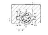
- Sheath unit 4 As shown in FIG. 1, the sheath unit 4 extends along the longitudinal axis C.
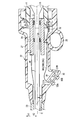
- the sheath unit 4 has a fixed handle 22 and a sheath 23 attached to the tip of the fixed handle 22.
- the fixed handle 22 has a handle casing 27 that functions as an exterior part.
- the handle casing 27 is provided in a later-described second opening / closing direction side portion of the handle casing 27 and has a fixed handle ring 28 that functions as a fixed-side finger rest.
- the handle casing 27 has a cylindrical member 29 provided inside the handle casing 27 and fixed to the handle casing 27.
- the proximal end of the probe 3 extends to the inside of the cylindrical member 29.
- the probe 3 is attached to the horn 15 as described above inside the cylindrical member 29.
- the cylindrical member 29 supports the probe 3 and the horn 15 via the insulating member 31. Thereby, the contact between the probe 3 and the horn 15 and the cylindrical member 29 is prevented, and the probe 3 and the horn 15 and the cylindrical member 29 are electrically insulated.
- An electrical connection ring 32 is provided on the outer peripheral side of the cylindrical member 29.
- the electrical connection ring 32 is provided in a state of being fixed to the handle casing 27. Between the tubular member 29 and the electrical connection ring 32, the distal end portion of the transducer case 11 is engaged.
- the vibrator case 11 is coupled to the fixed handle 22 (sheath unit 4) by engaging the distal end portion of the vibrator case 11 between the tubular member 29 and the electrical connection ring 32. In a state where the vibrator case 11 is coupled to the fixed handle 22, the outer peripheral portion of the tip portion of the vibrator case 11 is in contact with the electrical connection ring 32, and the inner peripheral portion of the tip portion of the vibrator case 11 is the cylindrical member 29. Is touching.
- the handle casing 27 is provided at a portion of the handle casing 27 (fixed handle 22) on the second opening / closing direction side (the direction of the arrow A2 shown in FIGS. 1 and 4).
- an inclined plane 33 inclined with respect to the longitudinal axis C is provided on the distal direction side of the fixed handle ring 28.
- the inclined plane 33 is located on the proximal direction side from the first opening / closing direction (the direction of arrow A1 shown in FIGS. 1 and 4) toward the second opening / closing direction.
- the inclined plane 33 is inclined upward from the distal direction side of the handle casing 27 toward the proximal direction side. For this reason, the angle between the inclined plane 33 and the longitudinal axis C has an acute angle ⁇ .
- the handle casing 27 has input buttons 35 ⁇ / b> A and 35 ⁇ / b> B that are two operation input units provided on the inclined plane 33.
- the operator's operation is input by pressing the input buttons 35A and 35B.
- the pressing direction of the input buttons 35 ⁇ / b> A and 35 ⁇ / b> B is perpendicular to the inclined plane 33.
- the handle casing 27 has switch portions 37 ⁇ / b> A and 37 ⁇ / b> B and an electric circuit board 38 provided on the inner peripheral side of the inclined plane 33.
- the open / closed state of the switch unit 37A is switched by an input operation using the input button 35A.
- the open / closed state of the switch unit 37B is switched by an input operation using the input button 35B.
- FIG. 5 is a diagram schematically showing an electrical connection state in the vibrator case 11, the cylindrical member 29, and the electrical connection ring 32.
- the handle casing 27 has three electric signal lines 39 ⁇ / b> A, 39 ⁇ / b> B, 39 ⁇ / b> C provided inside the handle casing 27.
- the electric signal line 39A is electrically connected to the switch unit 37A via the electric circuit board 38.
- the electric signal line 39B is electrically connected to the switch unit 37B via the electric circuit board 38.
- the electric signal line 39C is electrically connected to the switch unit 37A and the switch unit 37B via the electric circuit board 38.
- the electric signal line 39C is a common line shared as a ground line for the switch unit 37A and the switch unit 37B.
- the electrical connection ring 32 has a first electrical connection portion 42A, a second electrical connection portion 42B, and a third electrical connection portion 42C. Between the first electrical connection part 42A and the second electrical connection part 42B, between the second electrical connection part 42B and the third electrical connection part 42C, and between the first electrical connection part 42A and the third electrical connection part.
- the connection part 42C is electrically insulated.
- the electric signal line 39A is connected to the first electric connecting portion 42A.
- the electrical signal line 39B is connected to the second electrical connection portion 42B.
- the electric signal line 39C is connected to the third electric connecting portion 42C.
- the transducer case 11 has a first conductive portion 43A, a second conductive portion 43B, and a third conductive portion 43C.
- the first conductive portion 43A, the second conductive portion 43B, and the third conductive portion 43C are extended along the longitudinal axis C. Between the first conductive part 43A and the second conductive part 43B, between the second conductive part 43B and the third conductive part 43C, and between the first conductive part 43A and the third conductive part 43C. are electrically insulated.
- the distal end portion of the first conductive portion 43A is in electrical contact with only the first electrical connection portion 42A of the electrical connection ring 32.
- the distal end portion of the second conductive portion 43B is in electrical contact with only the second electrical connection portion 42B of the electrical connection ring 32.
- the distal end portion of the third conductive portion 43C is in electrical contact with only the third electrical connection portion 42C of the electrical connection ring 32.
- the base end portion of the first conductive portion 43 ⁇ / b> A is connected to one end of the electric signal line 45.
- a base end portion of the second conductive portion 43B is connected to one end of the electric signal line 46.
- a base end portion of the third conductive portion 43 ⁇ / b> C is connected to one end of the electric signal line 47.
- the electric signal lines 45, 46 and 47 are provided inside the cable 6. The other ends of the electric signal lines 45, 46, 47 are connected to the power supply unit 7.
- the first electrical signal path is formed from the switch portion 37A to the power supply unit 7 through the electrical signal line 39A, the first electrical connection portion 42A, the first conductive portion 43A, and the electrical signal line 45.
- a second electrical signal path is formed from the switch portion 37 ⁇ / b> B to the power supply unit 7 through the electrical signal line 39 ⁇ / b> B, the second electrical connection portion 42 ⁇ / b> B, the second conductive portion 43 ⁇ / b> B, and the electrical signal line 46.
- a ground path is formed from the switch unit 37A and the switch unit 37B to the power supply unit 7 through the electrical signal line 39C, the third electrical connection unit 42C, the third conductive unit 43C, and the electrical signal line 47. .
- the switch unit 37A When the input button 35A is pressed, the switch unit 37A is closed, and the first electrical signal path and the ground path are electrically connected by the switch unit 37A. Thereby, an electrical signal is transmitted from the switch part 37 ⁇ / b> A to the power supply unit 7. Then, for example, current is supplied from the ultrasonic control unit 8 to the ultrasonic transducer 12 via the electric signal lines 13A and 13B, and ultrasonic vibration is generated in the ultrasonic transducer 12, and at the same time, the high-frequency current control unit 9 generates a high frequency. It is switched to a state in which current is output. By pressing the input button 35B, the switch unit 37B is closed, and the second electrical signal path and the ground path are electrically connected by the switch unit 37B.
- an electrical signal is transmitted from the switch unit 37 ⁇ / b> B to the power supply unit 7.
- a high-frequency current is output only from the high-frequency current control unit 9 and the state is switched to a state in which no ultrasonic vibration is generated.
- the transducer case 11 further includes a fourth conductive portion 43D extending along the longitudinal axis C.
- the first conductive portion 43A, the second conductive portion 43B, and the third conductive portion 43C are all electrically insulated from the fourth conductive portion 43D.
- a base end portion of the fourth conductive portion 43 ⁇ / b> D is connected to one end of the electric signal line 48.
- the electric signal line 48 is provided inside the cable 6.
- the other end of the electric signal line 48 is connected to the high-frequency current control unit 9 of the power supply unit 7. In a state where the transducer case 11 is connected to the fixed handle 22 (sheath unit 4), only the tip end portion of the fourth conductive portion 43D is in electrical contact with the cylindrical member 29.
- the cylindrical member 29 is connected to one end of an electric signal line 49.
- the other end of the electric signal line 49 is connected to the sheath 23.
- a high-frequency current is transmitted between the high-frequency current control unit 9 and the sheath 23 via the electric signal line 48, the fourth conductive unit 43 ⁇ / b> D, the tubular member 29, and the electric signal line 49. .
- the sheath 23 is provided on the outer peripheral side of the probe 3.
- the probe 3 is inserted through the sheath 23 in a state where the first electrode portion 21 that functions as the tip of the probe 3 protrudes from the tip of the sheath 23.
- the sheath 23 is provided between the probe 3 and the sheath 23 in the radial direction of the sheath 23, and has a support member 51 that supports the probe 3.
- the support member 51 is made of an insulating material.
- the support member 51 prevents contact between the probe 3 and the sheath 23 and electrically insulates the probe 3 and the sheath 23 from each other.
- the support member 51 is disposed at a node position of ultrasonic vibration. Thereby, the contact between the probe 3 and the sheath 23 is prevented more effectively.
- the number of support members 51 may be one or more, and at least one support member 51 may be provided.
- the movable handle unit 5 can be opened and closed with respect to the fixed side including the probe 3 and the sheath unit 4 for a treatment operation for treating a treatment target.
- the movable handle unit 5 includes a movable handle 25 that is provided at the base end of the movable handle unit and functions as a power point in the treatment operation.
- the movable handle 25 can be opened / closed in the opening / closing direction with respect to the fixed handle 22 around the rotation axis R, which will be described later, perpendicular to the longitudinal axis C.
- the movable handle 25 has a movable handle ring 26 that functions as a movable side finger rest.
- the movable handle 25 is opposite to the first opening / closing direction (first direction) perpendicular to the longitudinal axis C shown in the direction of arrow A1 in FIG. 1 and the first opening / closing direction shown in the direction of arrow A2 in FIG.
- the fixed handle 22 can be opened and closed in a second opening / closing direction (second direction).
- the movable handle 25 is located closer to the first opening / closing direction than the fixed handle 22.
- the axis L1 of the movable handle 25 is inclined with an acute angle ⁇ with respect to the longitudinal axis C.
- the movable handle unit 5 further includes a jaw 52 rotatably attached to the distal end portion of the sheath 23 and a relay member 57 provided between the movable handle 25 and the jaw 52.
- the jaw 52 is provided at the distal end portion of the movable handle unit 5 and has a second electrode portion 53 that functions as a jaw distal end portion that functions as an action point in the treatment operation.
- the jaw 52 is attached to the distal end portion of the sheath 23 so as to be rotatable around a rotation axis R.
- the jaw 52 rotates in the longitudinal axis direction and the rotation axis direction with respect to the first electrode portion 21 that functions as the distal end portion of the probe 3 by rotating around the rotation axis R as the movable handle 25 is opened and closed. It intersects and can be opened and closed in the vertical opening and closing direction.
- the jaw 52 can be opened and closed with respect to the first electrode portion 21 provided at the distal end portion of the probe 3.
- the jaw 52 has a second electrode portion 53 positioned on the second opening / closing direction (the direction of the arrow A2 shown in FIGS. 1 and 6) from the first electrode portion 21 of the probe 3.
- the second electrode portion 53 is electrically connected to the sheath 23.
- the second electrode portion 53 is provided in a portion on the first opening / closing direction (arrow A1 direction shown in FIGS. 1 and 6) side of the outer surface of the second electrode portion 53 (jaw 52).
- a probe facing portion 55 facing the electrode portion 21 is provided.
- the first electrode portion 21 is provided at a portion of the outer surface of the first electrode portion 21 on the second opening / closing direction side (the direction of the arrow A2 shown in FIGS. 1 and 6). It has a jaw facing portion 58 facing the electrode portion 53.
- the movable handle unit 5 is provided at a connecting portion between the movable handle unit 5 and the sheath 23, and has a rotation axis R that functions as a rotation center.
- the rotation axis R is provided so as to intersect the longitudinal axis C, to be perpendicular to the longitudinal axis C, and to be perpendicular to the first opening / closing direction and the second opening / closing direction.
- the movable handle unit 5 rotates around this rotation axis. Therefore, by moving the movable handle 25 in the first opening / closing direction and opening the movable handle 25 with respect to the fixed handle 22, the jaw 52 moves in the second opening / closing direction. As a result, the jaw 52 is in the open position with respect to the first electrode portion 21.
- the jaw 52 moves in the first opening / closing direction.
- the jaw 52 is in the closed position with respect to the first electrode portion 21. That is, the jaw 52 rotates with respect to the sheath 23 about the rotation axis R, thereby opening and closing the first electrode portion 21 between the open position and the closed position.
- the second electrode portion 53 is electrically connected to the sheath 23. For this reason, a high frequency current is transmitted between the sheath 23 and the second electrode portion 53. A high frequency current is transmitted between the high frequency current control unit 9 and the sheath 23 via the electric signal line 48, the fourth conductive portion 43 ⁇ / b> D, and the electric signal line 49. Therefore, a jaw-side current path is formed from the high-frequency current control unit 9 to the second electrode unit 53 of the jaw 52 through the electrical signal line 48, the fourth conductive unit 43D, the electrical signal line 49, and the sheath 23. The That is, the high-frequency current is transmitted between the high-frequency current control unit 9 and the second electrode unit 53 through the jaw-side current path.
- an insulating coating process is performed on the outer surface of the sheath 23 and the outer surface of the jaw 52 other than the probe facing portion 55. For this reason, even when an operator's hand etc. contact the outer surface of the sheath 23 or the outer surface of the jaw 52, an electric shock is prevented.
- the relay member 57 between the jaw 52 and the movable handle 25 is formed of an insulating material. This prevents high-frequency current from being transmitted from the jaw 52 to the movable handle 25.
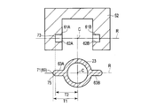
- Electrode 60 As shown in FIG. 7, the treatment instrument 10 is provided between the sheath 23 and the jaw 52, and always maintains a state in which a high-frequency current is transmitted between the sheath 23 and the second electrode portion 53 of the jaw 52.
- the electric contact unit 60 is further provided.
- the electrical contact unit 60 functions as a connecting portion that connects the sheath 23 and the jaw 52 in order to rotate the jaw 52 with respect to the sheath 23 around the rotation axis R.
- the electric contact unit 60 has a first groove-like portion 61A and a second groove-like portion 61B that are recessed in the outer peripheral direction along the rotation axis R in the jaw 52.
- the first groove-like portion 61A is recessed toward the first rotation axis direction (direction of arrow B1 shown in FIG. 7) parallel to the rotation axis R.
- the second groove-like portion 61B is recessed toward the second rotation axis direction (the direction of the arrow B2 shown in FIG. 7) which is the direction opposite to the first rotation axis direction.
- the first groove-shaped portion 61A is defined by the first groove defining portion 62A
- the second groove-shaped portion 61B is defined by the second groove defining portion 62B.
- the electrical contact unit 60 has a first protrusion 63A and a second protrusion 63B protruding in the outer peripheral direction along the rotation axis R on the outer peripheral portion of the sheath 23.
- the first protrusion 63A protrudes in the first rotation axis direction
- the second protrusion 63B protrudes in the second rotation axis direction.
- the first protrusion 63A is inserted into the first groove 61A
- the second protrusion 63B is inserted into the second groove 61B.
- FIG. 8 is a diagram showing the configuration of the first groove defining portion 62A and the first protrusion 63A.
- the configuration of the second groove defining portion 62B is the same as the configuration of the first groove defining portion 62A.
- the configuration of the second projection 63B is the same as the configuration of the first projection 63A. Therefore, the description of the second groove defining portion 62B and the second protrusion 63B is omitted.
- the first groove defining portion 62 ⁇ / b> A has a groove side surface 65 and a groove bottom surface 67.
- the first protrusion 63 ⁇ / b> A has a protruding end 69.
- the first protrusion 63A is inserted into the first groove 61A with a gap between the first protrusion 63A and the groove side surface 65.
- a sheath side contact portion 71 is located at the protruding end 69. That is, the sheath side contact portion 71 is provided on the outer peripheral portion of the sheath 23.
- the jaw side contact portion 73 is located on the groove bottom surface 67 of the first groove defining portion 62A of the jaw 52.
- the jaw side contact portion 73 is provided on the inner peripheral portion of the jaw 52.
- the jaw side contact portion 73 is slidably in contact with the sheath side contact portion 71.
- a high frequency current is transmitted between the sheath 23 and the second electrode portion 53 of the jaw 52.
- FIG. 9 is a view showing the sheath 23 and the jaw 52 in a state where the jaw 52 is not attached to the sheath 23.
- the first dimension T1 along the rotation axis R from the longitudinal axis C to the sheath side contact portion 71 is from the longitudinal axis C to the jaw. It becomes larger than the second dimension T2 along the rotation axis R to the side contact portion 73.
- the first protrusion 63 ⁇ / b> A includes a protrusion-side hemisphere portion 75 provided in a hemisphere along the rotation axis R up to the sheath-side contact portion 71.
- the protrusion-side hemispherical portion 75 is a protrusion-side cross-section changing portion in which the cross-sectional area perpendicular to the rotation axis R decreases along the rotation axis R toward the protruding end 69 of the first protrusion 63A.
- the protrusion-side hemispherical portion 75 reduces the contact area between the sheath-side contact portion 71 and the jaw-side contact portion 73.
- the treatment instrument 10 further includes, for example, an accelerating portion 100 provided in the movable handle unit 5 on the movable side.
- a treatment operation such as a gripping operation or a peeling operation
- the movable handle unit 5 receives the reaction force F from the treatment target 150 by the opening and closing operation
- the elastic deformation of the movable handle unit 5 in the direction in which the force F is received is promoted. As illustrated in FIG.
- the promotion unit 100 when the treatment operation is finished and the reaction force F is no longer applied to the movable handle unit 5, the promotion unit 100 returns to the original state in which the movable handle unit 5 indicates the state before the treatment operation is started. Thus, the elastic deformation of the movable handle unit 5 is promoted on the opposite side to the direction in which the reaction force F is received.
- the accelerating unit 100 is a jaw that functions as an action point in the treatment operation rather than the movable handle 25 side that functions as a power point in the treatment operation.
- 52 is provided on the second electrode portion 53 side provided on the tip end side of 52.
- the accelerating portion 100 is provided with the second electrode portion 53 provided at the distal end portion of the jaw 52 that functions as an action point in the treatment operation in the axial direction of the movable handle unit 5. And a rotation axis R that functions as a fulcrum in the treatment operation.
- the second electrode portion 53 that functions as an action point in the axial direction of the movable handle unit 5 and functions as a fulcrum.
- the reaction force F is most applied between the rotating shaft R and the rotating shaft R.
- the reaction force F is applied to the rotation axis R side rather than the second electrode portion 53 side.
- the load is most applied to the rotation axis R side, and the load needs to be received on the rotation axis R side.
- the accelerating portion 100 is provided in the axial direction of the movable handle unit 5 with the second portion provided on the distal end side of the jaw 52 that functions as an action point in the treatment operation. It is more preferable to be provided on the rotation axis R side that functions as a fulcrum in the treatment operation, rather than on the electrode part 53 side.
- such an accelerating portion 100 is positioned between the proximal end portion of the second electrode portion 53 and the rotation axis R in the axial direction of the movable handle unit 5, for example.
- the promotion portion 100 is formed by deforming a part of the jaw 52, is included in the jaw 52, and is integral with the jaw 52.
- the second electrode portion 53 warps (bends) in this opening direction around the promoting portion 100 in the jaw 52, the second electrode portion 53 moves away from the first electrode portion 21, and the jaw 52
- the accelerating portion 100 promotes the elastic deformation of the jaw 52 so that the jaw 52 receives the reaction force F from the straight state to the curved state.
- the second electrode part 53 warps (bends) in the closing direction around the accelerating part 100 in the jaw 52, the second electrode part 53 approaches the first electrode part 21, and the jaw 52
- the accelerating portion 100 promotes the elastic deformation of the jaw 52 so that the jaw 52 receives the reaction force F from the straight state to the curved state.
- the accelerating portion 100 is urged by the jaw 52 so that the second electrode portion 53 warps (bends) in the direction of receiving the reaction force F around the accelerating portion 100 in the jaw 52 and the jaw 52 receives the reaction force F. Promotes elastic deformation.
- the promotion unit 100 promotes elastic deformation of the jaw 52 so that the jaw 52 elastically deforms in a direction opposite to the direction in which the reaction force F is received. .
- the second electrode portion 53 rebounds (bends) in the direction opposite to the direction in which the reaction force F is received around the promotion portion 100 in the jaw 52, and the jaw 52 is promoted so as to change from the curved state to the straight state.
- the part 100 promotes elastic deformation of the jaw 52.
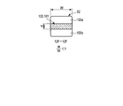
- the promoting portion 100 has a thinning portion 101 that is easily elastically deformed so that the jaw 52 is easily elastically deformed.
- the reduced thickness portion 101 is formed by reducing the thickness of the jaw 52 in the promotion portion 100 compared to the thickness of the jaw 52 other than the promotion portion 100 because the jaw 52 is elastically deformed around the promotion portion 100.
- the thickness of the jaw 52 in the reduced thickness portion 101 may be smaller than the thickness of the jaw 52 around the reduced thickness portion 101 excluding the reduced thickness portion 101.
- the periphery of the thinning portion 101 shows, for example, a jaw 52 between the rotation axis R and the promotion portion 100 and a jaw 52 between the second electrode portion 53 side that functions as an action point and the promotion portion 100. .
- the thinned portion 101 is provided directly on a part of the jaw 52, for example.
- the thinning portion 101 is provided so that a part of the jaw 52 functions as a circumflex portion formed in a wave shape along the central axis direction of the jaw 52.
- a part of the jaw 52 in the circumflex portion is thinner than the other part of the jaw 52.
- the maximum thickness of a part of the jaw 52 in the circumflex portion is substantially the same as the maximum thickness of the other part of the jaw 52.
- the thinning portion 101 includes, for example, an open-side groove 103 a that is recessed from the open-side end surface of the jaw 52 toward the close-side end surface of the jaw 52, and the close-side end surface. And a closed-side groove 103b that is recessed toward the end surface on the opening direction side.
- the opening direction side end surface is, for example, the surface of the jaw 52
- the closing direction side end surface is, for example, the back surface of the jaw 52.
- the opening direction side end surface is not in contact with the treatment target 150 during the gripping operation, and is in contact with the treatment target 150 during the peeling operation.
- the end surface on the closing direction contacts the treatment target 150 during the gripping operation, and does not contact the treatment target 150 during the peeling operation.
- the open side groove portion 103 a and the close side groove portion 103 b are alternately provided in the central axis direction of the jaw 52.
- the number of open side grooves 103a is preferably the same as the number of closed side grooves 103b. It is preferable that the depth of the open-side groove 103a and the depth of the closed-side groove 103b are the same. It is preferable that the length of the open side groove 103a and the length of the closed side groove 103b are the same.
- the open side groove portion 103 a and the close side groove portion 103 b are provided orthogonal to the central axis direction of the jaw 52, and are provided along the thickness direction of the jaw 52.
- the open side groove 103 a and the close side groove 103 b penetrate the jaw 52 in the width direction of the jaw 52.
- the open side groove 103a and the close side groove 103b function as slits.
- the thinned portion 101 is formed by providing the closed side groove portion 103b, and includes an open side thin portion 105a provided on the opening direction side end surface side of the jaw 52 and an open side groove portion 103a. And a closed-side thin portion 105b provided on the end surface side of the jaw 52 in the closing direction.
- the open-side thin portion 105 a and the closed-side thin portion 105 b are alternately provided in the central axis direction of the jaw 52.
- the open side thin portion 105 a is provided above the central axis of the jaw 52 in the thickness direction of the jaw 52, for example.
- the closed-side thin portion 105 b is provided below the central axis of the jaw 52 in the thickness direction of the jaw 52, for example.
- the open-side thin portion 105a and the closed-side thin portion 105b are formed by reducing the thickness of a part of the jaw 52 with respect to the maximum thickness of the jaw 52, and the jaw 52 is locally thinned. Become.
- the widths of the open-side thin portion 105 a and the closed-side thin portion 105 b are uniform with the width of the other portion of the jaw 52.
- the closed-side groove portion 103b is provided on the same straight line as the open-side thin portion 105a so as to face the open-side thin portion 105a.
- the open-side groove portion 103a is provided on the same straight line as the closed-side thin portion 105b so as to face the closed-side thin portion 105b.
- the thinned portion 101 further includes a thick portion 107 a that is connected to the open-side thin portion 105 a and the closed-side thin portion 105 b and has the same thickness as the other portion of the jaw 52.
- the thick portion 107 a is provided along the thickness direction of the jaw 52. In the central axis direction of the jaw 52, for example, the open-side groove portion 103a and the closed-side thin portion 105b, the thick-wall portion 107a, the closed-side groove portion 103b and the open-side thin-wall portion 105a, the thick-wall portion 107a, the open-side groove portion 103a, and the closed-side thin wall.
- the parts 105b and the thick parts 107a are arranged in this order. The number of each unit is not particularly limited.
- Such a promoting portion 100 also functions as a local cross-sectional portion where the cross-section of the jaw 52 is locally reduced.
- the promotion part 100 is configured such that the rigidity of a part of the jaw 52 is made larger than the rigidity of the other part by the open-side groove part 103a and the closed-side groove part 103b so that the rigidity of a part of the jaw 52 is lower than the rigidity of the other part. It is variable.
- the promotion part 100 promotes elastic deformation of the jaw 52, so that the second electrode part 53 warps (bends) in this opening direction around the promotion part 100 in the jaw 52, and the second The electrode portion 53 is separated from the first electrode portion 21, and the jaw 52 is changed from a straight state to a curved state.
- the jaw 52 can surely receive the reaction force F by the elastic deformation promoted by the promoting portion 100. Therefore, the jaw 52 is prevented from being gradually deformed by the reaction force F from the treatment target 150.
- the jaw 52 Since the jaw 52 is elastically deformed, the second electrode portion 53 can be brought into contact with the treatment target 150 along the peripheral surface of the treatment target 150. Therefore, the gripping force can be improved.
- the closed groove 103b in the direction of the central axis of the jaw 52 (the length of the closed groove 103b), the closed groove 103b widens, and the open groove 103a contacts the edges of the open groove 103a. Narrows.
- the jaw 52 is prevented from being extremely elastically deformed in the opening direction around the promoting portion 100, in other words, from being bent.
- the second electrode portion 53 approaches the first electrode portion 21, and the jaw 52 is changed from the curved state to the linear state. For this reason, the jaw 52 that is elastically deformed in the opening direction around the promoting portion 100 in the gripping operation is elastically deformed in the closing direction and reliably returns to the original state with the end of the gripping operation. That is, when the gripping operation is finished, the jaw 52 does not continue to maintain the deformed state during the gripping operation.
- the jaw 52 is in the linear state which is the initial state described above, and the first electrode grips the treatment target 150 together with the second electrode unit 53 in this initial state.
- the deformation of the jaw 52 is prevented by the promotion unit 100, and the operation force such as the gripping force is prevented from gradually decreasing.
- the closing amount when the operator closes the movable handle 25 with respect to the fixed handle 22 changes. It becomes. Specifically, if the jaw 52 or the like does not return from the deformed state during the gripping operation to the original state, the operator holds the movable handle 25 with respect to the fixed handle 22 with the closing amount A1 before the deforming during the gripping operation. Even if it is closed, there is a possibility that the gripping force B1 before deformation cannot be obtained.
- the gripping force must be closed unless the operator closes the movable handle 25 with respect to the fixed handle 22 with the closing amount A2 equal to or greater than the closing amount A1.
- B1 cannot be obtained. Therefore, the surgeon may get a feeling of strangeness in the operation.
- the gripping force corresponding to the closing amount is gradually reduced in this way, there is a possibility that the operability for gripping may gradually decrease due to the fact that the deformed state does not return to the original state during the gripping operation.
- the operation force such as the gripping force is prevented from gradually decreasing. For this reason, it is possible to prevent the grip operability from gradually decreasing due to a decrease in operating force such as gripping force.
- the promotion part 100 promotes elastic deformation of the jaw 52, so that the second electrode part 53 warps (bends) in this closing direction around the promotion part 100 in the jaw 52, and the second The electrode portion 53 approaches the first electrode portion 21, and the jaw 52 changes from a straight state to a curved state.
- the jaw 52 can surely receive the reaction force F by the elastic deformation promoted by the promoting portion 100. Therefore, the jaw 52 is prevented from being gradually deformed by the reaction force F from the treatment target 150.
- the jaw 52 Since the jaw 52 is elastically deformed, the second electrode portion 53 can be brought into contact with the treatment target 150 along the peripheral surface of the treatment target 150. Therefore, the peeling force can be improved.
- the second electrode portion 53 is separated from the second electrode portion 53, and the jaw 52 is changed from the curved state to the linear state.
- the jaw 52 that is elastically deformed in the closing direction around the accelerating portion 100 in the peeling operation is elastically deformed in the opening direction and reliably returns to the original state when the gripping operation is completed.
- the jaw 52 does not keep the deformed state during the peeling operation.
- the jaw 52 is in the linear state which is the initial state described above, and in this initial state, the first electrode portion 21 peels the treatment target 150 together with the second electrode portion 53. Become.
- the opening amount when the operator opens the movable handle 25 with respect to the fixed handle 22 changes. It becomes. Specifically, if the jaw 52 or the like does not return from the deformed state during the peeling operation to the original state, the operator holds the movable handle 25 with respect to the fixed handle 22 with the opening amount A1 before the deformation during the peeling operation. Even if it opens, there exists a possibility that peeling force B1 before a deformation
- the operation force such as the peeling force is prevented from gradually decreasing. For this reason, it is prevented that peeling operativity falls gradually resulting from the fall of operation power, such as peeling power.
- the jaw 52 can be elastically deformed by the promotion part 100. Therefore, even when the second electrode portion 53 receives the reaction force F from the treatment target 150 during the treatment operation such as the gripping operation or the peeling operation, the jaw 52 receives the reaction force F in the direction in which the reaction force F is received. be able to. Therefore, the jaw 52 is prevented from being gradually deformed by the reaction force F from the treatment target 150. When the treatment operation is finished, the jaw 52 can surely return to the original linear state. Then, when the treatment operation is started again, the jaw 52 is in the linear state which is the initial state described above, and in this initial state, the first electrode unit 21 can hold the treatment target 150 together with the second electrode unit 53. .
- the jaw 52 can be elastically deformed by the promoting portion 100. For this reason, in the treatment operation such as the gripping operation and the peeling operation, the second electrode unit 53 can be brought into contact with the treatment object 150 along the peripheral surface of the treatment object 150. Therefore, in this embodiment, it is also possible to improve treatment power such as gripping force and peeling force.
- the second electrode portion 53 side that functions as an action point in the axial direction of the movable handle unit 5 and functions as a fulcrum.
- the reaction force F is applied most between the rotating shaft R side.
- the reaction force F is applied to the rotation axis R side rather than the second electrode portion 53 side.
- the promotion part 100 is provided in the rotating shaft R side rather than the 2nd electrode part 53 side. Accordingly, elastic deformation can be promoted by the jaw 52 in this portion, and the jaw 52 can effectively receive the reaction force F, and the load on the jaw 52 can be reduced.
- the promotion part 100 has the thinning part 101 (a part of the jaw 52 that functions as a detour part). For this reason, in this embodiment, it is possible to prevent the jaw 52 from being deformed by the thinning portion 101 in both the gripping operation and the peeling operation, and to prevent the treatment force such as the gripping force and the peeling force from gradually decreasing. . Therefore, in this embodiment, it can prevent that the operativity of a treatment falls gradually resulting from this.
- the promotion part 100 has the open side groove part 103a and the closed side groove part 103b which are recessedly provided in the opening / closing direction of the jaw 52. Thereby, in this embodiment, the promotion part 100 can accelerate
- the promotion unit 100 can promote the elastic deformation of the jaw 52 so that the jaw 52 elastically deforms in the direction opposite to the direction in which the reaction force F is received.
- the promoting unit 100 promotes elastic deformation of the jaw 52, so that the opening and closing force is applied to the second electrode unit 53. It is possible to prevent direct transmission to the treatment object 150 via the. Therefore, in this embodiment, the promotion part 100 can prevent the opening / closing force from being directly transmitted to the treatment target 150 and excessively damaging the treatment target 150.
- the promotion part 100 may have only a closed-side groove part 103b, an open-side thin part 105a, and a thick part 107a.
- a plurality of closed side grooves 103b, open side thin portions 105a, and thick portions 107a are provided.
- the closed groove portions 103b are provided at equal distances from each other in the central axis direction of the jaw 52.
- the number of each unit is not particularly limited.
- the elastic deformation force indicating the warping force in the gripping operation is larger than the elastic deformation force in the peeling operation, unlike the elastic deformation force indicating the warping force in the peeling operation.
- the elastic deformation force indicating the warping force at the end of the peeling operation is larger than the elastic deformation force in the peeling operation. For this reason, in the treatment operation, a difference can be given to the elastic deformation, and a configuration specialized for the grasping operation can be achieved.
- the promoting part 100 may have only the open-side groove part 103a, the closed-side thin part 105b, and the thick part 107a.
- a plurality of open-side grooves 103a, closed-side thin portions 105b, and thick portions 107a are provided.
- the open-side grooves 103 a are provided at an equal distance from each other in the central axis direction of the jaw 52.
- the number of each unit is not particularly limited.
- the elastic deformation force indicating the warping force in the gripping operation is smaller than the elastic deformation force in the peeling operation, unlike the elastic deformation force indicating the warping force in the peeling operation.
- the elastic deformation force indicating the warping force at the end of the peeling operation is smaller than the elastic deformation force in the peeling operation. For this reason, in the treatment operation, a difference can be given to the elastic deformation, and a configuration specialized for the peeling operation can be achieved.
- the promotion part 100 should just have at least one of the closed side groove part 103b and the open side groove part 103a.
- the promotion part 100 may be provided with a plurality of discontinuities in the central axis direction of the jaw 52.
- the thinned portion 101 of the present embodiment is provided such that a part of the jaw 52 is thinner and flatter than the other part of the jaw 52 in the opening / closing direction of the jaw 52.
- the central axis of the thinned portion 101 is coaxial with the central axis of the entire jaw 52.
- the cross section of the thinned portion 101 orthogonal to the central axis of the jaw 52 has a bilaterally symmetric shape about the central axis in the thickness direction of the thinned portion 101 that is the opening and closing direction. For this reason, as shown in FIGS. 12A and 12F, the open-side groove 103 a and the closed-side groove 103 b are provided coaxially in the thickness direction of the jaw 52.
- the cross section has, for example, one of a rectangular shape shown in FIGS. 12B and 12F, a trapezoidal shape shown in FIGS. 12C and 12D, and an elliptical shape shown in FIG. 12E. When the cross section has a trapezoidal shape as shown in FIGS.
- the upper side may be shorter than the lower side as shown in FIG. 12C, or the upper side may be longer than the lower side as shown in FIG. 12D.
- the cross section has an upper surface that functions as an end surface on the opening direction side of the jaw 52 and a lower surface that functions as an end surface on the closing direction side of the jaw 52.
- the upper surface and the lower surface are flat.
- the width of the cross section which is the length of the upper side and the lower side, is W, If the height of the cross section is H, H / W ⁇ 1.
- the aforementioned thinned portion 101 also functions as a narrow-diameter portion where a part of the jaw 52 is thinner than the other part of the jaw 52.
- the structure of the promotion part 100 can be simplified and the promotion part 100 can be created easily.
- the central axis of the thinned portion 101 is parallel to the central axis of the entire jaw 52, and the cross section has a symmetrical shape. For this reason, it is possible to reliably obtain, for example, the amount of warping (deflection) that is the same elastic deformation amount in the gripping operation and the peeling operation, and the same elastic deformation amount at the end of the gripping operation and at the end of the peeling operation. For example, the return amount can be easily obtained.
- a plurality of the promoting portions 100 may be provided in the central axis direction of the jaw 52. In this case, it is preferable that the promoting portions 100 are separated from each other by an equal distance in the central axis direction of the jaw 52.
- the thinned portion 101 of this embodiment is provided so that a part of the jaw 52 functions as a curved portion formed in a wave shape along a direction orthogonal to the central axis direction of the jaw 52.
- the open side groove 103a and the close side groove 103b have, for example, an L shape.
- the open-side thin part 105a and the closed-side thin part 105b have, for example, an L shape.
- one side of the L shape is provided orthogonal to the central axis direction of the jaw 52, and the other side of the L shape is provided along the central axis direction of the jaw 52.
- the closed groove 103 b one side of the L shape is provided orthogonal to the central axis direction of the jaw 52, and the other side of the L shape is provided along the central axis direction of the jaw 52.
- the other sides of the L-shape are provided adjacent to each other in a direction orthogonal to the central axis direction of the jaw 52.
- the thinned portion 101 further includes a meat portion 107 b connected to the open side thin portion 105 a and the closed side thin portion 105 b and provided along the central axis direction of the jaw 52.
- the promotion part 100 may be provided in the second electrode part 53 that functions as a tip part of the jaw 52.
- the promoting portion 100 is provided along the central axis direction of the jaw 52, and has a notch portion 109 formed by notching a part of the tip portion of the jaw 52.
- the notch 109 is provided at the proximal end portion of the second electrode portion 53 that is the base portion of the distal end portion of the jaw 52.
- the promotion part 100 is provided in the front-end
- the second electrode portion 53 can be brought into contact with the treatment object along the peripheral surface of the treatment object.
- the notch portion 109 promotes elastic deformation of the second electrode portion 53, and the thinning portion 101 promotes elastic deformation of the jaw 52. For this reason, in this embodiment, the load on the jaw 52 can be further reduced in the gripping operation.
- the thickness of the promoting portion 100 is variable so as to increase from the distal end portion of the promoting portion 100 toward the proximal end portion of the promoting portion 100. May be. Thereby, the amount of elastic deformation can be adjusted.
- the distal end side of the open-side groove 103a is shallow and the proximal end side of the open-side groove 103a is deep.
- the depth of one open-side groove 103a may be variable.
- the open groove 103a provided on the distal end side of the promotion portion 100 is shallow, and the open groove 103a provided on the proximal end side of the promotion portion 100 is deep.
- the depth of the open-side groove 103a may be variable. Thereby, the amount of elastic deformation can be adjusted. The same applies to the closed groove 103b.
- the distance L1 between one open-side groove 103a and the other open-side groove 103a may be variable. Thereby, the amount of elastic deformation can be adjusted. The same applies to the closed groove 103b.
- each open groove 103a may be variable. Thereby, the amount of elastic deformation can be adjusted. Since the length of the open-side groove 103a is short, it is possible to prevent the treatment target from being caught in the open-side groove 103a. The same applies to the closed groove 103b.
- the angle ⁇ formed between the side surface of the open-side groove 103a and the bottom surface of the open-side groove 103a may be variable in each open-side groove 103a. Thereby, the amount of elastic deformation can be adjusted. It is possible to reduce stress concentration in the promoting portion 100. It is possible to prevent the treatment target from being caught in the open side groove 103a. The same applies to the closed groove 103b.
- the open groove 103a may have a curved surface 103c provided at the bottom of the open groove 103a. Thereby, the amount of elastic deformation can be adjusted. The same applies to the closed groove 103b.
- the number of the open side grooves 103a is not particularly limited. Thereby, the amount of elastic deformation can be adjusted. The same applies to the closed groove 103b.
- the width of the promoting portion 100 may be varied with respect to the width of the other portion of the jaw 52 so as to be thicker than the width of the other portion of the jaw 52. Thereby, an aspect ratio (H / L) can be earned, and the elastic deformation force in the opening / closing direction can be varied.
- the present invention is not limited to the above-described embodiment as it is, and can be embodied by modifying the constituent elements without departing from the scope of the invention in the implementation stage.
- Various inventions can be formed by appropriately combining a plurality of constituent elements disclosed in the embodiment.
Landscapes
- Health & Medical Sciences (AREA)
- Surgery (AREA)
- Engineering & Computer Science (AREA)
- Life Sciences & Earth Sciences (AREA)
- Biomedical Technology (AREA)
- Public Health (AREA)
- Nuclear Medicine, Radiotherapy & Molecular Imaging (AREA)
- Veterinary Medicine (AREA)
- General Health & Medical Sciences (AREA)
- Heart & Thoracic Surgery (AREA)
- Medical Informatics (AREA)
- Molecular Biology (AREA)
- Animal Behavior & Ethology (AREA)
- Physics & Mathematics (AREA)
- Otolaryngology (AREA)
- Plasma & Fusion (AREA)
- Dentistry (AREA)
- Mechanical Engineering (AREA)
- Surgical Instruments (AREA)
Priority Applications (3)
| Application Number | Priority Date | Filing Date | Title |
|---|---|---|---|
| CN201580002632.4A CN105764440B (zh) | 2014-01-16 | 2015-01-05 | 能量处理器具 |
| EP15737889.4A EP3095402A4 (en) | 2014-01-16 | 2015-01-05 | Energy treatment instrument |
| US15/074,518 US9770286B2 (en) | 2014-01-16 | 2016-03-18 | Energy treatment device |
Applications Claiming Priority (2)
| Application Number | Priority Date | Filing Date | Title |
|---|---|---|---|
| JP2014006108A JP5855684B2 (ja) | 2014-01-16 | 2014-01-16 | エネルギー処置具 |
| JP2014-006108 | 2014-01-16 |
Related Child Applications (1)
| Application Number | Title | Priority Date | Filing Date |
|---|---|---|---|
| US15/074,518 Continuation US9770286B2 (en) | 2014-01-16 | 2016-03-18 | Energy treatment device |
Publications (1)
| Publication Number | Publication Date |
|---|---|
| WO2015107916A1 true WO2015107916A1 (ja) | 2015-07-23 |
Family
ID=53542807
Family Applications (1)
| Application Number | Title | Priority Date | Filing Date |
|---|---|---|---|
| PCT/JP2015/050036 Ceased WO2015107916A1 (ja) | 2014-01-16 | 2015-01-05 | エネルギー処置具 |
Country Status (5)
| Country | Link |
|---|---|
| US (1) | US9770286B2 (enExample) |
| EP (1) | EP3095402A4 (enExample) |
| JP (1) | JP5855684B2 (enExample) |
| CN (1) | CN105764440B (enExample) |
| WO (1) | WO2015107916A1 (enExample) |
Cited By (1)
| Publication number | Priority date | Publication date | Assignee | Title |
|---|---|---|---|---|
| EP3572026A1 (en) * | 2015-10-19 | 2019-11-27 | Ethicon LLC | Surgical instrument with dual mode end effector and side-loaded clamp arm assembly |
Families Citing this family (2)
| Publication number | Priority date | Publication date | Assignee | Title |
|---|---|---|---|---|
| IS050190A (is) | 2017-09-29 | 2019-03-29 | Reon Ehf | Fjaðurbúnaður til að veita stigaða snertiendurgjöf |
| KR20240157066A (ko) * | 2022-03-21 | 2024-10-31 | 닝보 신웰 메디컬 테크놀로지 컴퍼니 리미티드 | 일체형 클립 부재 및 제조방법 |
Citations (4)
| Publication number | Priority date | Publication date | Assignee | Title |
|---|---|---|---|---|
| JP2000000249A (ja) * | 1998-04-16 | 2000-01-07 | Olympus Optical Co Ltd | 超音波処置具 |
| JP4727575B2 (ja) | 2004-06-15 | 2011-07-20 | オリンパス株式会社 | エネルギー処置具 |
| WO2012128362A1 (ja) * | 2011-03-24 | 2012-09-27 | オリンパスメディカルシステムズ株式会社 | 把持処置装置 |
| WO2014001200A1 (de) * | 2012-06-25 | 2014-01-03 | Olympus Winter & Ibe Gmbh | Greifinstrument |
Family Cites Families (8)
| Publication number | Priority date | Publication date | Assignee | Title |
|---|---|---|---|---|
| DE19608768C2 (de) * | 1996-03-07 | 1999-12-23 | Dieter Lang | Medizinische Zange |
| US6273887B1 (en) * | 1998-01-23 | 2001-08-14 | Olympus Optical Co., Ltd. | High-frequency treatment tool |
| US6736813B2 (en) * | 1998-01-23 | 2004-05-18 | Olympus Optical Co., Ltd. | High-frequency treatment tool |
| US20040097911A1 (en) * | 2001-02-13 | 2004-05-20 | Olympus Optical Co., Ltd. | Ultrasonic operating apparartus and tool for changing tip thereof |
| DE102006042985A1 (de) * | 2005-10-04 | 2007-04-19 | Erbe Elektromedizin Gmbh | Elektrochirurgisches Instrument |
| WO2011121827A1 (ja) * | 2010-03-31 | 2011-10-06 | オリンパスメディカルシステムズ株式会社 | 医療装置及び外科用処置具 |
| US9113909B2 (en) * | 2011-09-01 | 2015-08-25 | Covidien Lp | Surgical vessel sealer and divider |
| CN105943121B (zh) * | 2011-10-26 | 2018-05-25 | 奥林巴斯株式会社 | 超声波处理器具 |
-
2014
- 2014-01-16 JP JP2014006108A patent/JP5855684B2/ja active Active
-
2015
- 2015-01-05 EP EP15737889.4A patent/EP3095402A4/en not_active Withdrawn
- 2015-01-05 CN CN201580002632.4A patent/CN105764440B/zh active Active
- 2015-01-05 WO PCT/JP2015/050036 patent/WO2015107916A1/ja not_active Ceased
-
2016
- 2016-03-18 US US15/074,518 patent/US9770286B2/en active Active
Patent Citations (4)
| Publication number | Priority date | Publication date | Assignee | Title |
|---|---|---|---|---|
| JP2000000249A (ja) * | 1998-04-16 | 2000-01-07 | Olympus Optical Co Ltd | 超音波処置具 |
| JP4727575B2 (ja) | 2004-06-15 | 2011-07-20 | オリンパス株式会社 | エネルギー処置具 |
| WO2012128362A1 (ja) * | 2011-03-24 | 2012-09-27 | オリンパスメディカルシステムズ株式会社 | 把持処置装置 |
| WO2014001200A1 (de) * | 2012-06-25 | 2014-01-03 | Olympus Winter & Ibe Gmbh | Greifinstrument |
Non-Patent Citations (1)
| Title |
|---|
| See also references of EP3095402A4 |
Cited By (6)
| Publication number | Priority date | Publication date | Assignee | Title |
|---|---|---|---|---|
| EP3572026A1 (en) * | 2015-10-19 | 2019-11-27 | Ethicon LLC | Surgical instrument with dual mode end effector and side-loaded clamp arm assembly |
| US10893914B2 (en) | 2015-10-19 | 2021-01-19 | Ethicon Llc | Surgical instrument with dual mode end effector and modular clamp arm assembly |
| US11020200B2 (en) | 2015-10-19 | 2021-06-01 | Ethicon Llc | Surgical instrument with dual mode end effector and compound lever with detents |
| US11045275B2 (en) | 2015-10-19 | 2021-06-29 | Cilag Gmbh International | Surgical instrument with dual mode end effector and side-loaded clamp arm assembly |
| EP3364893B1 (en) * | 2015-10-19 | 2022-03-02 | Ethicon LLC | Surgical instrument with dual mode end effector and side-loaded clamp arm assembly |
| US12245899B2 (en) | 2015-10-19 | 2025-03-11 | Cilag Gmbh International | Surgical instrument with dual mode end effector and modular clamp arm assembly |
Also Published As
| Publication number | Publication date |
|---|---|
| JP5855684B2 (ja) | 2016-02-09 |
| US20160199121A1 (en) | 2016-07-14 |
| US9770286B2 (en) | 2017-09-26 |
| JP2015134029A (ja) | 2015-07-27 |
| CN105764440B (zh) | 2019-04-02 |
| EP3095402A1 (en) | 2016-11-23 |
| CN105764440A (zh) | 2016-07-13 |
| EP3095402A4 (en) | 2017-09-13 |
Similar Documents
| Publication | Publication Date | Title |
|---|---|---|
| CN101543426B (zh) | 外科手术装置 | |
| CN103717160B (zh) | 把持处理装置 | |
| CN105246423A (zh) | 把持处理装置和把持单元 | |
| CN101370440B (zh) | 凝固切开装置 | |
| JP4035100B2 (ja) | 医療用処置具及びこれを備えた医療用処置装置 | |
| EP3205303A1 (en) | Grasping treatment unit and grasping treatment tool | |
| US8702701B2 (en) | Treatment device for electrosurgery | |
| JPWO2012128362A1 (ja) | 把持処置装置 | |
| CN101396300A (zh) | 外科手术装置 | |
| US10010342B2 (en) | Ultrasonic probe and ultrasonic treatment apparatus | |
| CN108472057B (zh) | 手术器具和连接器 | |
| JP5855684B2 (ja) | エネルギー処置具 | |
| JP6153686B2 (ja) | 医療用部材、医療機器 | |
| US11000302B2 (en) | Grasping treatment instrument | |
| JP6227208B2 (ja) | エネルギー処置具 | |
| JP6017736B2 (ja) | 処置装置 | |
| US12471983B2 (en) | Treatment instrument, treatment system, and control method | |
| WO2018087841A1 (ja) | 振動伝達部材及び超音波処置具 | |
| CN106457308A (zh) | 振动产生单元、振动体单元以及超声波处置器具 | |
| EP3406214B1 (en) | Medical apparatus, medical apparatus system | |
| US20230048948A1 (en) | Treatment instrument | |
| JP6197131B2 (ja) | 外科手術装置 | |
| WO2016075745A1 (ja) | 医療用処置装置 | |
| JP4253517B2 (ja) | 超音波処置装置 | |
| WO2017216909A1 (ja) | 処置具及び制御装置 |
Legal Events
| Date | Code | Title | Description |
|---|---|---|---|
| 121 | Ep: the epo has been informed by wipo that ep was designated in this application |
Ref document number: 15737889 Country of ref document: EP Kind code of ref document: A1 |
|
| NENP | Non-entry into the national phase |
Ref country code: DE |
|
| REEP | Request for entry into the european phase |
Ref document number: 2015737889 Country of ref document: EP |
|
| WWE | Wipo information: entry into national phase |
Ref document number: 2015737889 Country of ref document: EP |