WO2015107916A1 - Energy treatment instrument - Google Patents
Energy treatment instrument Download PDFInfo
- Publication number
- WO2015107916A1 WO2015107916A1 PCT/JP2015/050036 JP2015050036W WO2015107916A1 WO 2015107916 A1 WO2015107916 A1 WO 2015107916A1 JP 2015050036 W JP2015050036 W JP 2015050036W WO 2015107916 A1 WO2015107916 A1 WO 2015107916A1
- Authority
- WO
- WIPO (PCT)
- Prior art keywords
- jaw
- movable handle
- closed
- open
- unit
- Prior art date
Links
Images


Classifications
-
- A—HUMAN NECESSITIES
- A61—MEDICAL OR VETERINARY SCIENCE; HYGIENE
- A61B—DIAGNOSIS; SURGERY; IDENTIFICATION
- A61B18/00—Surgical instruments, devices or methods for transferring non-mechanical forms of energy to or from the body
- A61B18/04—Surgical instruments, devices or methods for transferring non-mechanical forms of energy to or from the body by heating
- A61B18/12—Surgical instruments, devices or methods for transferring non-mechanical forms of energy to or from the body by heating by passing a current through the tissue to be heated, e.g. high-frequency current
- A61B18/14—Probes or electrodes therefor
- A61B18/1442—Probes having pivoting end effectors, e.g. forceps
-
- A—HUMAN NECESSITIES
- A61—MEDICAL OR VETERINARY SCIENCE; HYGIENE
- A61B—DIAGNOSIS; SURGERY; IDENTIFICATION
- A61B17/00—Surgical instruments, devices or methods, e.g. tourniquets
- A61B17/32—Surgical cutting instruments
- A61B17/320068—Surgical cutting instruments using mechanical vibrations, e.g. ultrasonic
- A61B17/320092—Surgical cutting instruments using mechanical vibrations, e.g. ultrasonic with additional movable means for clamping or cutting tissue, e.g. with a pivoting jaw
-
- A—HUMAN NECESSITIES
- A61—MEDICAL OR VETERINARY SCIENCE; HYGIENE
- A61B—DIAGNOSIS; SURGERY; IDENTIFICATION
- A61B18/00—Surgical instruments, devices or methods for transferring non-mechanical forms of energy to or from the body
- A61B18/04—Surgical instruments, devices or methods for transferring non-mechanical forms of energy to or from the body by heating
- A61B18/12—Surgical instruments, devices or methods for transferring non-mechanical forms of energy to or from the body by heating by passing a current through the tissue to be heated, e.g. high-frequency current
- A61B18/1206—Generators therefor
-
- A—HUMAN NECESSITIES
- A61—MEDICAL OR VETERINARY SCIENCE; HYGIENE
- A61B—DIAGNOSIS; SURGERY; IDENTIFICATION
- A61B18/00—Surgical instruments, devices or methods for transferring non-mechanical forms of energy to or from the body
- A61B18/04—Surgical instruments, devices or methods for transferring non-mechanical forms of energy to or from the body by heating
- A61B18/12—Surgical instruments, devices or methods for transferring non-mechanical forms of energy to or from the body by heating by passing a current through the tissue to be heated, e.g. high-frequency current
- A61B18/14—Probes or electrodes therefor
- A61B18/1442—Probes having pivoting end effectors, e.g. forceps
- A61B18/1445—Probes having pivoting end effectors, e.g. forceps at the distal end of a shaft, e.g. forceps or scissors at the end of a rigid rod
-
- A—HUMAN NECESSITIES
- A61—MEDICAL OR VETERINARY SCIENCE; HYGIENE
- A61B—DIAGNOSIS; SURGERY; IDENTIFICATION
- A61B18/00—Surgical instruments, devices or methods for transferring non-mechanical forms of energy to or from the body
- A61B18/04—Surgical instruments, devices or methods for transferring non-mechanical forms of energy to or from the body by heating
- A61B18/12—Surgical instruments, devices or methods for transferring non-mechanical forms of energy to or from the body by heating by passing a current through the tissue to be heated, e.g. high-frequency current
- A61B18/14—Probes or electrodes therefor
- A61B18/1482—Probes or electrodes therefor having a long rigid shaft for accessing the inner body transcutaneously in minimal invasive surgery, e.g. laparoscopy
-
- A—HUMAN NECESSITIES
- A61—MEDICAL OR VETERINARY SCIENCE; HYGIENE
- A61B—DIAGNOSIS; SURGERY; IDENTIFICATION
- A61B18/00—Surgical instruments, devices or methods for transferring non-mechanical forms of energy to or from the body
- A61B18/04—Surgical instruments, devices or methods for transferring non-mechanical forms of energy to or from the body by heating
- A61B18/12—Surgical instruments, devices or methods for transferring non-mechanical forms of energy to or from the body by heating by passing a current through the tissue to be heated, e.g. high-frequency current
- A61B18/14—Probes or electrodes therefor
- A61B18/1485—Probes or electrodes therefor having a short rigid shaft for accessing the inner body through natural openings
-
- A—HUMAN NECESSITIES
- A61—MEDICAL OR VETERINARY SCIENCE; HYGIENE
- A61B—DIAGNOSIS; SURGERY; IDENTIFICATION
- A61B17/00—Surgical instruments, devices or methods, e.g. tourniquets
- A61B17/32—Surgical cutting instruments
- A61B17/320068—Surgical cutting instruments using mechanical vibrations, e.g. ultrasonic
- A61B2017/320072—Working tips with special features, e.g. extending parts
-
- A—HUMAN NECESSITIES
- A61—MEDICAL OR VETERINARY SCIENCE; HYGIENE
- A61B—DIAGNOSIS; SURGERY; IDENTIFICATION
- A61B17/00—Surgical instruments, devices or methods, e.g. tourniquets
- A61B17/32—Surgical cutting instruments
- A61B17/320068—Surgical cutting instruments using mechanical vibrations, e.g. ultrasonic
- A61B2017/320088—Surgical cutting instruments using mechanical vibrations, e.g. ultrasonic with acoustic insulation, e.g. elements for damping vibrations between horn and surrounding sheath
-
- A—HUMAN NECESSITIES
- A61—MEDICAL OR VETERINARY SCIENCE; HYGIENE
- A61B—DIAGNOSIS; SURGERY; IDENTIFICATION
- A61B18/00—Surgical instruments, devices or methods for transferring non-mechanical forms of energy to or from the body
- A61B2018/00994—Surgical instruments, devices or methods for transferring non-mechanical forms of energy to or from the body combining two or more different kinds of non-mechanical energy or combining one or more non-mechanical energies with ultrasound
-
- A—HUMAN NECESSITIES
- A61—MEDICAL OR VETERINARY SCIENCE; HYGIENE
- A61B—DIAGNOSIS; SURGERY; IDENTIFICATION
- A61B18/00—Surgical instruments, devices or methods for transferring non-mechanical forms of energy to or from the body
- A61B18/04—Surgical instruments, devices or methods for transferring non-mechanical forms of energy to or from the body by heating
- A61B18/12—Surgical instruments, devices or methods for transferring non-mechanical forms of energy to or from the body by heating by passing a current through the tissue to be heated, e.g. high-frequency current
- A61B18/14—Probes or electrodes therefor
- A61B18/1442—Probes having pivoting end effectors, e.g. forceps
- A61B2018/1452—Probes having pivoting end effectors, e.g. forceps including means for cutting
-
- A—HUMAN NECESSITIES
- A61—MEDICAL OR VETERINARY SCIENCE; HYGIENE
- A61B—DIAGNOSIS; SURGERY; IDENTIFICATION
- A61B18/00—Surgical instruments, devices or methods for transferring non-mechanical forms of energy to or from the body
- A61B18/04—Surgical instruments, devices or methods for transferring non-mechanical forms of energy to or from the body by heating
- A61B18/12—Surgical instruments, devices or methods for transferring non-mechanical forms of energy to or from the body by heating by passing a current through the tissue to be heated, e.g. high-frequency current
- A61B18/14—Probes or electrodes therefor
- A61B2018/1465—Deformable electrodes
Definitions
- the present invention relates to a forceps-type energy treatment device in which a distal end portion of a jaw is opened and closed with respect to a distal end portion of a probe by opening and closing a movable handle with respect to a fixed handle.
- a general forceps-type energy treatment device has a probe and a jaw that can be opened and closed with respect to the probe.
- the tip of the jaw is closed with respect to the tip of the probe so that the tip of the jaw and the tip of the probe sandwich the treatment target such as a living tissue and grip the treatment target.
- the tip of the jaw opens with respect to the tip of the probe so that the tip of the jaw and the tip of the probe are pushed into the treatment object, for example, and the treatment object is spread and separated.
- Patent Document 1 An energy treatment instrument that performs the gripping operation and the peeling operation as described above is disclosed in Patent Document 1, for example.
- the entire jaw including the tip of the jaw is formed of a highly rigid member (for example, metal).
- a highly rigid member for example, metal
- the jaw may be gradually deformed by a reaction force from the treatment target.
- the deformed jaw has high jaw rigidity, there is a possibility that the deformed jaw does not return to the original state. As a result, there is a possibility that treatment power such as gripping force and peeling force gradually decreases.
- the present invention has been made in view of these circumstances, and an object of the present invention is to provide an energy treatment device that can prevent the treatment power from gradually decreasing even if the treatment operation is repeated.
- One aspect of the energy treatment device of the present invention includes a probe extending along a longitudinal axis, a fixed handle, and a probe attached to a distal end of the fixed handle, with the distal end portion of the probe protruding from the distal end.
- a sheath unit extending through the longitudinal axis, and a fixed side including the probe and the sheath unit for a treatment operation for treating a treatment target.
- a movable handle unit that can be opened and closed, and the movable handle unit that is openable and closable, and that the movable handle unit opens and closes with respect to the fixed side for the treatment operation.
- an accelerating portion that promotes elastic deformation of the movable handle unit in the direction of receiving the reaction force when receiving a force.
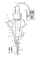
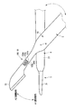
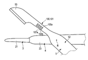
- FIG. 1 is a schematic view of a medical treatment apparatus according to the first embodiment of the present invention.
- FIG. 2 is a cross-sectional view showing the configuration of the vibrator unit.
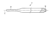
- FIG. 3 is a side view including a partial cross section of the probe.
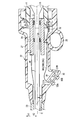
- FIG. 4 is a schematic cross-sectional view showing an internal configuration of the fixed handle.
- FIG. 5 is a schematic diagram illustrating an electrical connection state in the vibrator case, the cylindrical member, and the electrical connection ring.
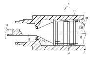
- FIG. 6 is a schematic cross-sectional view showing a state where the probe is inserted through the sheath according to the first embodiment.
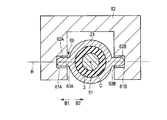
- 7 is a cross-sectional view taken along line VII-VII shown in FIG. FIG.
- FIG. 8 is a schematic cross-sectional view illustrating the configuration of the first groove defining portion and the first protrusion of the electrical contact unit according to the first embodiment.
- FIG. 9 is a schematic cross-sectional view showing the sheath and the jaw in a state where the jaw is not attached to the sheath according to the first embodiment.
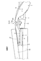
- FIG. 10A is a diagram illustrating a configuration of the promotion unit according to the first embodiment.
- FIG. 10B is a diagram illustrating the action of the promotion unit in the gripping operation.
- FIG. 10C is a diagram illustrating the action of the promoting portion in the peeling operation.
- FIG. 11A is a diagram illustrating a configuration of a promotion unit according to a first modification of the first embodiment.
- FIG. 11B is a diagram illustrating a configuration of a promotion unit according to a second modification of the first embodiment.
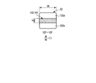
- FIG. 12A is a diagram illustrating a configuration of a promotion unit according to the second embodiment.
- FIG. 12B is a diagram illustrating an example of a cross section of the promoting portion.
- FIG. 12C is a diagram illustrating an example of a cross section of the promoting portion.
- FIG. 12D is a diagram illustrating an example of a cross section of the promoting portion.
- FIG. 12E is a diagram illustrating an example of a cross section of the promoting portion.
- 12F is a cross-sectional view taken along line 12F-12F shown in FIG. 12A.
- FIG. 13 is a diagram illustrating a configuration of the promotion unit according to the third embodiment.
- FIG. 12A is a diagram illustrating a configuration of a promotion unit according to the second embodiment.
- FIG. 12B is a diagram illustrating an example of a cross section of the promoting
- FIG. 14 is a diagram illustrating a configuration of a promotion unit according to the fourth embodiment.
- FIG. 15A is a diagram illustrating an example of a constituent member of the promotion unit according to the fifth embodiment.
- FIG. 15B is a diagram illustrating a configuration of a promotion unit according to the fifth embodiment.
- a medical treatment apparatus 1 shown in FIG. 1 is positioned at a distal end portion of a first electrode portion 21 located at a distal end portion of a probe 3 and a jaw 52 described later.
- a treatment target such as a living tissue is sandwiched and held by the second electrode unit 53 that performs the above operation.
- the gripping is performed by closing (approaching) the second electrode portion 53 with respect to the first electrode portion 21.
- the medical treatment apparatus 1 can treat the grasped treatment target with energy such as ultrasonic waves, high frequencies, and heat.
- Such a medical treatment apparatus 1 is a grasping treatment apparatus.
- the medical treatment apparatus 1 of the present embodiment is also used as a bipolar treatment apparatus that treats with a high-frequency current using the distal end portion of the probe 3 and the jaw 52 as electrodes.
- the medical treatment apparatus 1 is also used as an ultrasonic treatment apparatus that performs treatment by ultrasonic vibration.
- the medical treatment apparatus 1 is pushed into the treatment target and peels off the treatment target by the tip portion of the probe 3 and the jaw 52. As shown in FIG. 10C, the peeling is performed by opening (separating) the second electrode portion 53 from the first electrode portion 21.
- the medical treatment apparatus 1 includes a power supply unit 7 that functions as a supply unit that supplies electric power for energy, and a treatment instrument 10 that treats a treatment target with the energy supplied from the power supply unit 7. have.
- the power supply unit 7 includes an ultrasonic control unit 8 that controls a current for ultrasonic vibration and a high-frequency current control unit 9 that controls a current for high frequency.
- the power supply unit 7 further includes a cable 6 that is electrically connected to the ultrasonic control unit 8 and the treatment instrument 10 and electrically connected to the high-frequency current control unit 9 and the treatment instrument 10.
- One end of the cable 6 is connected to the power supply unit 7, and the other end of the cable 6 is connected to a base end of a vibrator case 11 described later.
- the treatment instrument 10 includes a transducer unit 2, a probe 3, a sheath unit 4, and a movable handle unit 5.
- the transducer unit 2, the probe 3, and the sheath unit 4 are fixed sides, and the movable handle unit 5 is a movable side that is movable so as to be rotatable with respect to the fixed side.
- the vibrator unit 2 As shown in FIGS. 1 and 2, the vibrator unit 2 has a vibrator case 11. As described above, the base end of the vibrator case 11 is connected to the end of the cable 6.
- the transducer unit 2 includes an ultrasonic transducer 12 that is provided inside the transducer case 11 and has a piezoelectric element that converts the current supplied from the ultrasonic control unit 8 into ultrasonic vibration. Have.
- the ultrasonic transducer 12 is connected to one end of the electric signal lines 13A and 13B.
- the electric signal lines 13 ⁇ / b> A and 13 ⁇ / b> B are provided inside the cable 6.
- the other ends of the electric signal lines 13 ⁇ / b> A and 13 ⁇ / b> B are connected to the ultrasonic control unit 8 of the power supply unit 7.
- an electric current is supplied from the ultrasonic control unit 8 to the ultrasonic transducer 12 via the electric signal lines 13 ⁇ / b> A and 13 ⁇ / b> B, ultrasonic vibration is generated in the ultrasonic transducer 12.
- the ultrasonic transducer 12 is connected to one end of the electrical signal line 17 separately from the electrical signal lines 13A and 13B.
- the electric signal line 17 is provided inside the cable 6.
- the other end of the electric signal line 17 is connected to the high frequency current control unit 9 of the power supply unit 7.
- the electric signal lines 13A, 13B, and 17 are included in the cable 6.
- the transducer unit 2 is connected to the tip of the ultrasonic transducer 12 so as to be located at the tip of the ultrasonic transducer 12, and the amplitude of the ultrasonic vibration generated by the ultrasonic transducer 12 is changed. It further has an expanding horn 15.
- the horn 15 is attached to the vibrator case 11 via an insulating member 15a.
- the horn 15 is electrically insulated from the vibrator case 11 by an insulating member 15a.
- the horn 15 has a female screw portion 16 formed at the tip of the horn 15.
- the probe 3 extends along the longitudinal axis C.
- the probe 3 has a column shape.
- the probe 3 has a male screw portion 19 that is formed at the base end portion of the probe 3 and is screwed into the female screw portion 16 of the horn 15.
- the probe 3 is attached to the horn 15 by screwing. Thereby, the ultrasonic vibration generated by the ultrasonic vibrator 12 is transmitted to the tip of the probe 3 through the horn 15 and the probe 3. That is, the ultrasonic vibration is transmitted from the proximal end of the probe 3 to the distal end.
- the ultrasonic vibration is longitudinal vibration in which the vibration transmission direction and the vibration direction coincide with each other.
- a probe-side current path for high-frequency current is formed from the high-frequency current control unit 9 to the tip of the probe 3 through the electric signal line 17, the ultrasonic transducer 12 and the horn 15.
- the probe 3 has a first electrode portion 21 formed at the distal end portion of the probe 3. That is, the high-frequency current is transmitted along the longitudinal axis C between the high-frequency current control unit 9 and the first electrode unit 21 by the probe-side current path.
- Sheath unit 4 As shown in FIG. 1, the sheath unit 4 extends along the longitudinal axis C.
- the sheath unit 4 has a fixed handle 22 and a sheath 23 attached to the tip of the fixed handle 22.
- the fixed handle 22 has a handle casing 27 that functions as an exterior part.
- the handle casing 27 is provided in a later-described second opening / closing direction side portion of the handle casing 27 and has a fixed handle ring 28 that functions as a fixed-side finger rest.
- the handle casing 27 has a cylindrical member 29 provided inside the handle casing 27 and fixed to the handle casing 27.
- the proximal end of the probe 3 extends to the inside of the cylindrical member 29.
- the probe 3 is attached to the horn 15 as described above inside the cylindrical member 29.
- the cylindrical member 29 supports the probe 3 and the horn 15 via the insulating member 31. Thereby, the contact between the probe 3 and the horn 15 and the cylindrical member 29 is prevented, and the probe 3 and the horn 15 and the cylindrical member 29 are electrically insulated.
- An electrical connection ring 32 is provided on the outer peripheral side of the cylindrical member 29.
- the electrical connection ring 32 is provided in a state of being fixed to the handle casing 27. Between the tubular member 29 and the electrical connection ring 32, the distal end portion of the transducer case 11 is engaged.
- the vibrator case 11 is coupled to the fixed handle 22 (sheath unit 4) by engaging the distal end portion of the vibrator case 11 between the tubular member 29 and the electrical connection ring 32. In a state where the vibrator case 11 is coupled to the fixed handle 22, the outer peripheral portion of the tip portion of the vibrator case 11 is in contact with the electrical connection ring 32, and the inner peripheral portion of the tip portion of the vibrator case 11 is the cylindrical member 29. Is touching.
- the handle casing 27 is provided at a portion of the handle casing 27 (fixed handle 22) on the second opening / closing direction side (the direction of the arrow A2 shown in FIGS. 1 and 4).
- an inclined plane 33 inclined with respect to the longitudinal axis C is provided on the distal direction side of the fixed handle ring 28.
- the inclined plane 33 is located on the proximal direction side from the first opening / closing direction (the direction of arrow A1 shown in FIGS. 1 and 4) toward the second opening / closing direction.
- the inclined plane 33 is inclined upward from the distal direction side of the handle casing 27 toward the proximal direction side. For this reason, the angle between the inclined plane 33 and the longitudinal axis C has an acute angle ⁇ .
- the handle casing 27 has input buttons 35 ⁇ / b> A and 35 ⁇ / b> B that are two operation input units provided on the inclined plane 33.
- the operator's operation is input by pressing the input buttons 35A and 35B.
- the pressing direction of the input buttons 35 ⁇ / b> A and 35 ⁇ / b> B is perpendicular to the inclined plane 33.
- the handle casing 27 has switch portions 37 ⁇ / b> A and 37 ⁇ / b> B and an electric circuit board 38 provided on the inner peripheral side of the inclined plane 33.
- the open / closed state of the switch unit 37A is switched by an input operation using the input button 35A.
- the open / closed state of the switch unit 37B is switched by an input operation using the input button 35B.
- FIG. 5 is a diagram schematically showing an electrical connection state in the vibrator case 11, the cylindrical member 29, and the electrical connection ring 32.
- the handle casing 27 has three electric signal lines 39 ⁇ / b> A, 39 ⁇ / b> B, 39 ⁇ / b> C provided inside the handle casing 27.
- the electric signal line 39A is electrically connected to the switch unit 37A via the electric circuit board 38.
- the electric signal line 39B is electrically connected to the switch unit 37B via the electric circuit board 38.
- the electric signal line 39C is electrically connected to the switch unit 37A and the switch unit 37B via the electric circuit board 38.
- the electric signal line 39C is a common line shared as a ground line for the switch unit 37A and the switch unit 37B.
- the electrical connection ring 32 has a first electrical connection portion 42A, a second electrical connection portion 42B, and a third electrical connection portion 42C. Between the first electrical connection part 42A and the second electrical connection part 42B, between the second electrical connection part 42B and the third electrical connection part 42C, and between the first electrical connection part 42A and the third electrical connection part.
- the connection part 42C is electrically insulated.
- the electric signal line 39A is connected to the first electric connecting portion 42A.
- the electrical signal line 39B is connected to the second electrical connection portion 42B.
- the electric signal line 39C is connected to the third electric connecting portion 42C.
- the transducer case 11 has a first conductive portion 43A, a second conductive portion 43B, and a third conductive portion 43C.
- the first conductive portion 43A, the second conductive portion 43B, and the third conductive portion 43C are extended along the longitudinal axis C. Between the first conductive part 43A and the second conductive part 43B, between the second conductive part 43B and the third conductive part 43C, and between the first conductive part 43A and the third conductive part 43C. are electrically insulated.
- the distal end portion of the first conductive portion 43A is in electrical contact with only the first electrical connection portion 42A of the electrical connection ring 32.
- the distal end portion of the second conductive portion 43B is in electrical contact with only the second electrical connection portion 42B of the electrical connection ring 32.
- the distal end portion of the third conductive portion 43C is in electrical contact with only the third electrical connection portion 42C of the electrical connection ring 32.
- the base end portion of the first conductive portion 43 ⁇ / b> A is connected to one end of the electric signal line 45.
- a base end portion of the second conductive portion 43B is connected to one end of the electric signal line 46.
- a base end portion of the third conductive portion 43 ⁇ / b> C is connected to one end of the electric signal line 47.
- the electric signal lines 45, 46 and 47 are provided inside the cable 6. The other ends of the electric signal lines 45, 46, 47 are connected to the power supply unit 7.
- the first electrical signal path is formed from the switch portion 37A to the power supply unit 7 through the electrical signal line 39A, the first electrical connection portion 42A, the first conductive portion 43A, and the electrical signal line 45.
- a second electrical signal path is formed from the switch portion 37 ⁇ / b> B to the power supply unit 7 through the electrical signal line 39 ⁇ / b> B, the second electrical connection portion 42 ⁇ / b> B, the second conductive portion 43 ⁇ / b> B, and the electrical signal line 46.
- a ground path is formed from the switch unit 37A and the switch unit 37B to the power supply unit 7 through the electrical signal line 39C, the third electrical connection unit 42C, the third conductive unit 43C, and the electrical signal line 47. .
- the switch unit 37A When the input button 35A is pressed, the switch unit 37A is closed, and the first electrical signal path and the ground path are electrically connected by the switch unit 37A. Thereby, an electrical signal is transmitted from the switch part 37 ⁇ / b> A to the power supply unit 7. Then, for example, current is supplied from the ultrasonic control unit 8 to the ultrasonic transducer 12 via the electric signal lines 13A and 13B, and ultrasonic vibration is generated in the ultrasonic transducer 12, and at the same time, the high-frequency current control unit 9 generates a high frequency. It is switched to a state in which current is output. By pressing the input button 35B, the switch unit 37B is closed, and the second electrical signal path and the ground path are electrically connected by the switch unit 37B.
- an electrical signal is transmitted from the switch unit 37 ⁇ / b> B to the power supply unit 7.
- a high-frequency current is output only from the high-frequency current control unit 9 and the state is switched to a state in which no ultrasonic vibration is generated.
- the transducer case 11 further includes a fourth conductive portion 43D extending along the longitudinal axis C.
- the first conductive portion 43A, the second conductive portion 43B, and the third conductive portion 43C are all electrically insulated from the fourth conductive portion 43D.
- a base end portion of the fourth conductive portion 43 ⁇ / b> D is connected to one end of the electric signal line 48.
- the electric signal line 48 is provided inside the cable 6.
- the other end of the electric signal line 48 is connected to the high-frequency current control unit 9 of the power supply unit 7. In a state where the transducer case 11 is connected to the fixed handle 22 (sheath unit 4), only the tip end portion of the fourth conductive portion 43D is in electrical contact with the cylindrical member 29.
- the cylindrical member 29 is connected to one end of an electric signal line 49.
- the other end of the electric signal line 49 is connected to the sheath 23.
- a high-frequency current is transmitted between the high-frequency current control unit 9 and the sheath 23 via the electric signal line 48, the fourth conductive unit 43 ⁇ / b> D, the tubular member 29, and the electric signal line 49. .
- the sheath 23 is provided on the outer peripheral side of the probe 3.
- the probe 3 is inserted through the sheath 23 in a state where the first electrode portion 21 that functions as the tip of the probe 3 protrudes from the tip of the sheath 23.
- the sheath 23 is provided between the probe 3 and the sheath 23 in the radial direction of the sheath 23, and has a support member 51 that supports the probe 3.
- the support member 51 is made of an insulating material.
- the support member 51 prevents contact between the probe 3 and the sheath 23 and electrically insulates the probe 3 and the sheath 23 from each other.
- the support member 51 is disposed at a node position of ultrasonic vibration. Thereby, the contact between the probe 3 and the sheath 23 is prevented more effectively.
- the number of support members 51 may be one or more, and at least one support member 51 may be provided.
- the movable handle unit 5 can be opened and closed with respect to the fixed side including the probe 3 and the sheath unit 4 for a treatment operation for treating a treatment target.
- the movable handle unit 5 includes a movable handle 25 that is provided at the base end of the movable handle unit and functions as a power point in the treatment operation.
- the movable handle 25 can be opened / closed in the opening / closing direction with respect to the fixed handle 22 around the rotation axis R, which will be described later, perpendicular to the longitudinal axis C.
- the movable handle 25 has a movable handle ring 26 that functions as a movable side finger rest.
- the movable handle 25 is opposite to the first opening / closing direction (first direction) perpendicular to the longitudinal axis C shown in the direction of arrow A1 in FIG. 1 and the first opening / closing direction shown in the direction of arrow A2 in FIG.
- the fixed handle 22 can be opened and closed in a second opening / closing direction (second direction).
- the movable handle 25 is located closer to the first opening / closing direction than the fixed handle 22.
- the axis L1 of the movable handle 25 is inclined with an acute angle ⁇ with respect to the longitudinal axis C.
- the movable handle unit 5 further includes a jaw 52 rotatably attached to the distal end portion of the sheath 23 and a relay member 57 provided between the movable handle 25 and the jaw 52.
- the jaw 52 is provided at the distal end portion of the movable handle unit 5 and has a second electrode portion 53 that functions as a jaw distal end portion that functions as an action point in the treatment operation.
- the jaw 52 is attached to the distal end portion of the sheath 23 so as to be rotatable around a rotation axis R.
- the jaw 52 rotates in the longitudinal axis direction and the rotation axis direction with respect to the first electrode portion 21 that functions as the distal end portion of the probe 3 by rotating around the rotation axis R as the movable handle 25 is opened and closed. It intersects and can be opened and closed in the vertical opening and closing direction.
- the jaw 52 can be opened and closed with respect to the first electrode portion 21 provided at the distal end portion of the probe 3.
- the jaw 52 has a second electrode portion 53 positioned on the second opening / closing direction (the direction of the arrow A2 shown in FIGS. 1 and 6) from the first electrode portion 21 of the probe 3.
- the second electrode portion 53 is electrically connected to the sheath 23.
- the second electrode portion 53 is provided in a portion on the first opening / closing direction (arrow A1 direction shown in FIGS. 1 and 6) side of the outer surface of the second electrode portion 53 (jaw 52).
- a probe facing portion 55 facing the electrode portion 21 is provided.
- the first electrode portion 21 is provided at a portion of the outer surface of the first electrode portion 21 on the second opening / closing direction side (the direction of the arrow A2 shown in FIGS. 1 and 6). It has a jaw facing portion 58 facing the electrode portion 53.
- the movable handle unit 5 is provided at a connecting portion between the movable handle unit 5 and the sheath 23, and has a rotation axis R that functions as a rotation center.
- the rotation axis R is provided so as to intersect the longitudinal axis C, to be perpendicular to the longitudinal axis C, and to be perpendicular to the first opening / closing direction and the second opening / closing direction.
- the movable handle unit 5 rotates around this rotation axis. Therefore, by moving the movable handle 25 in the first opening / closing direction and opening the movable handle 25 with respect to the fixed handle 22, the jaw 52 moves in the second opening / closing direction. As a result, the jaw 52 is in the open position with respect to the first electrode portion 21.
- the jaw 52 moves in the first opening / closing direction.
- the jaw 52 is in the closed position with respect to the first electrode portion 21. That is, the jaw 52 rotates with respect to the sheath 23 about the rotation axis R, thereby opening and closing the first electrode portion 21 between the open position and the closed position.
- the second electrode portion 53 is electrically connected to the sheath 23. For this reason, a high frequency current is transmitted between the sheath 23 and the second electrode portion 53. A high frequency current is transmitted between the high frequency current control unit 9 and the sheath 23 via the electric signal line 48, the fourth conductive portion 43 ⁇ / b> D, and the electric signal line 49. Therefore, a jaw-side current path is formed from the high-frequency current control unit 9 to the second electrode unit 53 of the jaw 52 through the electrical signal line 48, the fourth conductive unit 43D, the electrical signal line 49, and the sheath 23. The That is, the high-frequency current is transmitted between the high-frequency current control unit 9 and the second electrode unit 53 through the jaw-side current path.
- an insulating coating process is performed on the outer surface of the sheath 23 and the outer surface of the jaw 52 other than the probe facing portion 55. For this reason, even when an operator's hand etc. contact the outer surface of the sheath 23 or the outer surface of the jaw 52, an electric shock is prevented.
- the relay member 57 between the jaw 52 and the movable handle 25 is formed of an insulating material. This prevents high-frequency current from being transmitted from the jaw 52 to the movable handle 25.
- Electrode 60 As shown in FIG. 7, the treatment instrument 10 is provided between the sheath 23 and the jaw 52, and always maintains a state in which a high-frequency current is transmitted between the sheath 23 and the second electrode portion 53 of the jaw 52.
- the electric contact unit 60 is further provided.
- the electrical contact unit 60 functions as a connecting portion that connects the sheath 23 and the jaw 52 in order to rotate the jaw 52 with respect to the sheath 23 around the rotation axis R.
- the electric contact unit 60 has a first groove-like portion 61A and a second groove-like portion 61B that are recessed in the outer peripheral direction along the rotation axis R in the jaw 52.
- the first groove-like portion 61A is recessed toward the first rotation axis direction (direction of arrow B1 shown in FIG. 7) parallel to the rotation axis R.
- the second groove-like portion 61B is recessed toward the second rotation axis direction (the direction of the arrow B2 shown in FIG. 7) which is the direction opposite to the first rotation axis direction.
- the first groove-shaped portion 61A is defined by the first groove defining portion 62A
- the second groove-shaped portion 61B is defined by the second groove defining portion 62B.
- the electrical contact unit 60 has a first protrusion 63A and a second protrusion 63B protruding in the outer peripheral direction along the rotation axis R on the outer peripheral portion of the sheath 23.
- the first protrusion 63A protrudes in the first rotation axis direction
- the second protrusion 63B protrudes in the second rotation axis direction.
- the first protrusion 63A is inserted into the first groove 61A
- the second protrusion 63B is inserted into the second groove 61B.
- FIG. 8 is a diagram showing the configuration of the first groove defining portion 62A and the first protrusion 63A.
- the configuration of the second groove defining portion 62B is the same as the configuration of the first groove defining portion 62A.
- the configuration of the second projection 63B is the same as the configuration of the first projection 63A. Therefore, the description of the second groove defining portion 62B and the second protrusion 63B is omitted.
- the first groove defining portion 62 ⁇ / b> A has a groove side surface 65 and a groove bottom surface 67.
- the first protrusion 63 ⁇ / b> A has a protruding end 69.
- the first protrusion 63A is inserted into the first groove 61A with a gap between the first protrusion 63A and the groove side surface 65.
- a sheath side contact portion 71 is located at the protruding end 69. That is, the sheath side contact portion 71 is provided on the outer peripheral portion of the sheath 23.
- the jaw side contact portion 73 is located on the groove bottom surface 67 of the first groove defining portion 62A of the jaw 52.
- the jaw side contact portion 73 is provided on the inner peripheral portion of the jaw 52.
- the jaw side contact portion 73 is slidably in contact with the sheath side contact portion 71.
- a high frequency current is transmitted between the sheath 23 and the second electrode portion 53 of the jaw 52.
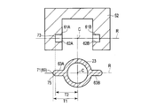
- FIG. 9 is a view showing the sheath 23 and the jaw 52 in a state where the jaw 52 is not attached to the sheath 23.
- the first dimension T1 along the rotation axis R from the longitudinal axis C to the sheath side contact portion 71 is from the longitudinal axis C to the jaw. It becomes larger than the second dimension T2 along the rotation axis R to the side contact portion 73.
- the first protrusion 63 ⁇ / b> A includes a protrusion-side hemisphere portion 75 provided in a hemisphere along the rotation axis R up to the sheath-side contact portion 71.
- the protrusion-side hemispherical portion 75 is a protrusion-side cross-section changing portion in which the cross-sectional area perpendicular to the rotation axis R decreases along the rotation axis R toward the protruding end 69 of the first protrusion 63A.
- the protrusion-side hemispherical portion 75 reduces the contact area between the sheath-side contact portion 71 and the jaw-side contact portion 73.
- the treatment instrument 10 further includes, for example, an accelerating portion 100 provided in the movable handle unit 5 on the movable side.
- a treatment operation such as a gripping operation or a peeling operation
- the movable handle unit 5 receives the reaction force F from the treatment target 150 by the opening and closing operation
- the elastic deformation of the movable handle unit 5 in the direction in which the force F is received is promoted. As illustrated in FIG.
- the promotion unit 100 when the treatment operation is finished and the reaction force F is no longer applied to the movable handle unit 5, the promotion unit 100 returns to the original state in which the movable handle unit 5 indicates the state before the treatment operation is started. Thus, the elastic deformation of the movable handle unit 5 is promoted on the opposite side to the direction in which the reaction force F is received.
- the accelerating unit 100 is a jaw that functions as an action point in the treatment operation rather than the movable handle 25 side that functions as a power point in the treatment operation.
- 52 is provided on the second electrode portion 53 side provided on the tip end side of 52.
- the accelerating portion 100 is provided with the second electrode portion 53 provided at the distal end portion of the jaw 52 that functions as an action point in the treatment operation in the axial direction of the movable handle unit 5. And a rotation axis R that functions as a fulcrum in the treatment operation.
- the second electrode portion 53 that functions as an action point in the axial direction of the movable handle unit 5 and functions as a fulcrum.
- the reaction force F is most applied between the rotating shaft R and the rotating shaft R.
- the reaction force F is applied to the rotation axis R side rather than the second electrode portion 53 side.
- the load is most applied to the rotation axis R side, and the load needs to be received on the rotation axis R side.
- the accelerating portion 100 is provided in the axial direction of the movable handle unit 5 with the second portion provided on the distal end side of the jaw 52 that functions as an action point in the treatment operation. It is more preferable to be provided on the rotation axis R side that functions as a fulcrum in the treatment operation, rather than on the electrode part 53 side.
- such an accelerating portion 100 is positioned between the proximal end portion of the second electrode portion 53 and the rotation axis R in the axial direction of the movable handle unit 5, for example.
- the promotion portion 100 is formed by deforming a part of the jaw 52, is included in the jaw 52, and is integral with the jaw 52.
- the second electrode portion 53 warps (bends) in this opening direction around the promoting portion 100 in the jaw 52, the second electrode portion 53 moves away from the first electrode portion 21, and the jaw 52
- the accelerating portion 100 promotes the elastic deformation of the jaw 52 so that the jaw 52 receives the reaction force F from the straight state to the curved state.
- the second electrode part 53 warps (bends) in the closing direction around the accelerating part 100 in the jaw 52, the second electrode part 53 approaches the first electrode part 21, and the jaw 52
- the accelerating portion 100 promotes the elastic deformation of the jaw 52 so that the jaw 52 receives the reaction force F from the straight state to the curved state.
- the accelerating portion 100 is urged by the jaw 52 so that the second electrode portion 53 warps (bends) in the direction of receiving the reaction force F around the accelerating portion 100 in the jaw 52 and the jaw 52 receives the reaction force F. Promotes elastic deformation.
- the promotion unit 100 promotes elastic deformation of the jaw 52 so that the jaw 52 elastically deforms in a direction opposite to the direction in which the reaction force F is received. .
- the second electrode portion 53 rebounds (bends) in the direction opposite to the direction in which the reaction force F is received around the promotion portion 100 in the jaw 52, and the jaw 52 is promoted so as to change from the curved state to the straight state.
- the part 100 promotes elastic deformation of the jaw 52.
- the promoting portion 100 has a thinning portion 101 that is easily elastically deformed so that the jaw 52 is easily elastically deformed.
- the reduced thickness portion 101 is formed by reducing the thickness of the jaw 52 in the promotion portion 100 compared to the thickness of the jaw 52 other than the promotion portion 100 because the jaw 52 is elastically deformed around the promotion portion 100.
- the thickness of the jaw 52 in the reduced thickness portion 101 may be smaller than the thickness of the jaw 52 around the reduced thickness portion 101 excluding the reduced thickness portion 101.
- the periphery of the thinning portion 101 shows, for example, a jaw 52 between the rotation axis R and the promotion portion 100 and a jaw 52 between the second electrode portion 53 side that functions as an action point and the promotion portion 100. .
- the thinned portion 101 is provided directly on a part of the jaw 52, for example.
- the thinning portion 101 is provided so that a part of the jaw 52 functions as a circumflex portion formed in a wave shape along the central axis direction of the jaw 52.
- a part of the jaw 52 in the circumflex portion is thinner than the other part of the jaw 52.
- the maximum thickness of a part of the jaw 52 in the circumflex portion is substantially the same as the maximum thickness of the other part of the jaw 52.
- the thinning portion 101 includes, for example, an open-side groove 103 a that is recessed from the open-side end surface of the jaw 52 toward the close-side end surface of the jaw 52, and the close-side end surface. And a closed-side groove 103b that is recessed toward the end surface on the opening direction side.
- the opening direction side end surface is, for example, the surface of the jaw 52
- the closing direction side end surface is, for example, the back surface of the jaw 52.
- the opening direction side end surface is not in contact with the treatment target 150 during the gripping operation, and is in contact with the treatment target 150 during the peeling operation.
- the end surface on the closing direction contacts the treatment target 150 during the gripping operation, and does not contact the treatment target 150 during the peeling operation.
- the open side groove portion 103 a and the close side groove portion 103 b are alternately provided in the central axis direction of the jaw 52.
- the number of open side grooves 103a is preferably the same as the number of closed side grooves 103b. It is preferable that the depth of the open-side groove 103a and the depth of the closed-side groove 103b are the same. It is preferable that the length of the open side groove 103a and the length of the closed side groove 103b are the same.
- the open side groove portion 103 a and the close side groove portion 103 b are provided orthogonal to the central axis direction of the jaw 52, and are provided along the thickness direction of the jaw 52.
- the open side groove 103 a and the close side groove 103 b penetrate the jaw 52 in the width direction of the jaw 52.
- the open side groove 103a and the close side groove 103b function as slits.
- the thinned portion 101 is formed by providing the closed side groove portion 103b, and includes an open side thin portion 105a provided on the opening direction side end surface side of the jaw 52 and an open side groove portion 103a. And a closed-side thin portion 105b provided on the end surface side of the jaw 52 in the closing direction.
- the open-side thin portion 105 a and the closed-side thin portion 105 b are alternately provided in the central axis direction of the jaw 52.
- the open side thin portion 105 a is provided above the central axis of the jaw 52 in the thickness direction of the jaw 52, for example.
- the closed-side thin portion 105 b is provided below the central axis of the jaw 52 in the thickness direction of the jaw 52, for example.
- the open-side thin portion 105a and the closed-side thin portion 105b are formed by reducing the thickness of a part of the jaw 52 with respect to the maximum thickness of the jaw 52, and the jaw 52 is locally thinned. Become.
- the widths of the open-side thin portion 105 a and the closed-side thin portion 105 b are uniform with the width of the other portion of the jaw 52.
- the closed-side groove portion 103b is provided on the same straight line as the open-side thin portion 105a so as to face the open-side thin portion 105a.
- the open-side groove portion 103a is provided on the same straight line as the closed-side thin portion 105b so as to face the closed-side thin portion 105b.
- the thinned portion 101 further includes a thick portion 107 a that is connected to the open-side thin portion 105 a and the closed-side thin portion 105 b and has the same thickness as the other portion of the jaw 52.
- the thick portion 107 a is provided along the thickness direction of the jaw 52. In the central axis direction of the jaw 52, for example, the open-side groove portion 103a and the closed-side thin portion 105b, the thick-wall portion 107a, the closed-side groove portion 103b and the open-side thin-wall portion 105a, the thick-wall portion 107a, the open-side groove portion 103a, and the closed-side thin wall.
- the parts 105b and the thick parts 107a are arranged in this order. The number of each unit is not particularly limited.
- Such a promoting portion 100 also functions as a local cross-sectional portion where the cross-section of the jaw 52 is locally reduced.
- the promotion part 100 is configured such that the rigidity of a part of the jaw 52 is made larger than the rigidity of the other part by the open-side groove part 103a and the closed-side groove part 103b so that the rigidity of a part of the jaw 52 is lower than the rigidity of the other part. It is variable.
- the promotion part 100 promotes elastic deformation of the jaw 52, so that the second electrode part 53 warps (bends) in this opening direction around the promotion part 100 in the jaw 52, and the second The electrode portion 53 is separated from the first electrode portion 21, and the jaw 52 is changed from a straight state to a curved state.
- the jaw 52 can surely receive the reaction force F by the elastic deformation promoted by the promoting portion 100. Therefore, the jaw 52 is prevented from being gradually deformed by the reaction force F from the treatment target 150.
- the jaw 52 Since the jaw 52 is elastically deformed, the second electrode portion 53 can be brought into contact with the treatment target 150 along the peripheral surface of the treatment target 150. Therefore, the gripping force can be improved.
- the closed groove 103b in the direction of the central axis of the jaw 52 (the length of the closed groove 103b), the closed groove 103b widens, and the open groove 103a contacts the edges of the open groove 103a. Narrows.
- the jaw 52 is prevented from being extremely elastically deformed in the opening direction around the promoting portion 100, in other words, from being bent.
- the second electrode portion 53 approaches the first electrode portion 21, and the jaw 52 is changed from the curved state to the linear state. For this reason, the jaw 52 that is elastically deformed in the opening direction around the promoting portion 100 in the gripping operation is elastically deformed in the closing direction and reliably returns to the original state with the end of the gripping operation. That is, when the gripping operation is finished, the jaw 52 does not continue to maintain the deformed state during the gripping operation.
- the jaw 52 is in the linear state which is the initial state described above, and the first electrode grips the treatment target 150 together with the second electrode unit 53 in this initial state.
- the deformation of the jaw 52 is prevented by the promotion unit 100, and the operation force such as the gripping force is prevented from gradually decreasing.
- the closing amount when the operator closes the movable handle 25 with respect to the fixed handle 22 changes. It becomes. Specifically, if the jaw 52 or the like does not return from the deformed state during the gripping operation to the original state, the operator holds the movable handle 25 with respect to the fixed handle 22 with the closing amount A1 before the deforming during the gripping operation. Even if it is closed, there is a possibility that the gripping force B1 before deformation cannot be obtained.
- the gripping force must be closed unless the operator closes the movable handle 25 with respect to the fixed handle 22 with the closing amount A2 equal to or greater than the closing amount A1.
- B1 cannot be obtained. Therefore, the surgeon may get a feeling of strangeness in the operation.
- the gripping force corresponding to the closing amount is gradually reduced in this way, there is a possibility that the operability for gripping may gradually decrease due to the fact that the deformed state does not return to the original state during the gripping operation.
- the operation force such as the gripping force is prevented from gradually decreasing. For this reason, it is possible to prevent the grip operability from gradually decreasing due to a decrease in operating force such as gripping force.
- the promotion part 100 promotes elastic deformation of the jaw 52, so that the second electrode part 53 warps (bends) in this closing direction around the promotion part 100 in the jaw 52, and the second The electrode portion 53 approaches the first electrode portion 21, and the jaw 52 changes from a straight state to a curved state.
- the jaw 52 can surely receive the reaction force F by the elastic deformation promoted by the promoting portion 100. Therefore, the jaw 52 is prevented from being gradually deformed by the reaction force F from the treatment target 150.
- the jaw 52 Since the jaw 52 is elastically deformed, the second electrode portion 53 can be brought into contact with the treatment target 150 along the peripheral surface of the treatment target 150. Therefore, the peeling force can be improved.
- the second electrode portion 53 is separated from the second electrode portion 53, and the jaw 52 is changed from the curved state to the linear state.
- the jaw 52 that is elastically deformed in the closing direction around the accelerating portion 100 in the peeling operation is elastically deformed in the opening direction and reliably returns to the original state when the gripping operation is completed.
- the jaw 52 does not keep the deformed state during the peeling operation.
- the jaw 52 is in the linear state which is the initial state described above, and in this initial state, the first electrode portion 21 peels the treatment target 150 together with the second electrode portion 53. Become.
- the opening amount when the operator opens the movable handle 25 with respect to the fixed handle 22 changes. It becomes. Specifically, if the jaw 52 or the like does not return from the deformed state during the peeling operation to the original state, the operator holds the movable handle 25 with respect to the fixed handle 22 with the opening amount A1 before the deformation during the peeling operation. Even if it opens, there exists a possibility that peeling force B1 before a deformation
- the operation force such as the peeling force is prevented from gradually decreasing. For this reason, it is prevented that peeling operativity falls gradually resulting from the fall of operation power, such as peeling power.
- the jaw 52 can be elastically deformed by the promotion part 100. Therefore, even when the second electrode portion 53 receives the reaction force F from the treatment target 150 during the treatment operation such as the gripping operation or the peeling operation, the jaw 52 receives the reaction force F in the direction in which the reaction force F is received. be able to. Therefore, the jaw 52 is prevented from being gradually deformed by the reaction force F from the treatment target 150. When the treatment operation is finished, the jaw 52 can surely return to the original linear state. Then, when the treatment operation is started again, the jaw 52 is in the linear state which is the initial state described above, and in this initial state, the first electrode unit 21 can hold the treatment target 150 together with the second electrode unit 53. .
- the jaw 52 can be elastically deformed by the promoting portion 100. For this reason, in the treatment operation such as the gripping operation and the peeling operation, the second electrode unit 53 can be brought into contact with the treatment object 150 along the peripheral surface of the treatment object 150. Therefore, in this embodiment, it is also possible to improve treatment power such as gripping force and peeling force.
- the second electrode portion 53 side that functions as an action point in the axial direction of the movable handle unit 5 and functions as a fulcrum.
- the reaction force F is applied most between the rotating shaft R side.
- the reaction force F is applied to the rotation axis R side rather than the second electrode portion 53 side.
- the promotion part 100 is provided in the rotating shaft R side rather than the 2nd electrode part 53 side. Accordingly, elastic deformation can be promoted by the jaw 52 in this portion, and the jaw 52 can effectively receive the reaction force F, and the load on the jaw 52 can be reduced.
- the promotion part 100 has the thinning part 101 (a part of the jaw 52 that functions as a detour part). For this reason, in this embodiment, it is possible to prevent the jaw 52 from being deformed by the thinning portion 101 in both the gripping operation and the peeling operation, and to prevent the treatment force such as the gripping force and the peeling force from gradually decreasing. . Therefore, in this embodiment, it can prevent that the operativity of a treatment falls gradually resulting from this.
- the promotion part 100 has the open side groove part 103a and the closed side groove part 103b which are recessedly provided in the opening / closing direction of the jaw 52. Thereby, in this embodiment, the promotion part 100 can accelerate
- the promotion unit 100 can promote the elastic deformation of the jaw 52 so that the jaw 52 elastically deforms in the direction opposite to the direction in which the reaction force F is received.
- the promoting unit 100 promotes elastic deformation of the jaw 52, so that the opening and closing force is applied to the second electrode unit 53. It is possible to prevent direct transmission to the treatment object 150 via the. Therefore, in this embodiment, the promotion part 100 can prevent the opening / closing force from being directly transmitted to the treatment target 150 and excessively damaging the treatment target 150.
- the promotion part 100 may have only a closed-side groove part 103b, an open-side thin part 105a, and a thick part 107a.
- a plurality of closed side grooves 103b, open side thin portions 105a, and thick portions 107a are provided.
- the closed groove portions 103b are provided at equal distances from each other in the central axis direction of the jaw 52.
- the number of each unit is not particularly limited.
- the elastic deformation force indicating the warping force in the gripping operation is larger than the elastic deformation force in the peeling operation, unlike the elastic deformation force indicating the warping force in the peeling operation.
- the elastic deformation force indicating the warping force at the end of the peeling operation is larger than the elastic deformation force in the peeling operation. For this reason, in the treatment operation, a difference can be given to the elastic deformation, and a configuration specialized for the grasping operation can be achieved.
- the promoting part 100 may have only the open-side groove part 103a, the closed-side thin part 105b, and the thick part 107a.
- a plurality of open-side grooves 103a, closed-side thin portions 105b, and thick portions 107a are provided.
- the open-side grooves 103 a are provided at an equal distance from each other in the central axis direction of the jaw 52.
- the number of each unit is not particularly limited.
- the elastic deformation force indicating the warping force in the gripping operation is smaller than the elastic deformation force in the peeling operation, unlike the elastic deformation force indicating the warping force in the peeling operation.
- the elastic deformation force indicating the warping force at the end of the peeling operation is smaller than the elastic deformation force in the peeling operation. For this reason, in the treatment operation, a difference can be given to the elastic deformation, and a configuration specialized for the peeling operation can be achieved.
- the promotion part 100 should just have at least one of the closed side groove part 103b and the open side groove part 103a.
- the promotion part 100 may be provided with a plurality of discontinuities in the central axis direction of the jaw 52.
- the thinned portion 101 of the present embodiment is provided such that a part of the jaw 52 is thinner and flatter than the other part of the jaw 52 in the opening / closing direction of the jaw 52.
- the central axis of the thinned portion 101 is coaxial with the central axis of the entire jaw 52.
- the cross section of the thinned portion 101 orthogonal to the central axis of the jaw 52 has a bilaterally symmetric shape about the central axis in the thickness direction of the thinned portion 101 that is the opening and closing direction. For this reason, as shown in FIGS. 12A and 12F, the open-side groove 103 a and the closed-side groove 103 b are provided coaxially in the thickness direction of the jaw 52.
- the cross section has, for example, one of a rectangular shape shown in FIGS. 12B and 12F, a trapezoidal shape shown in FIGS. 12C and 12D, and an elliptical shape shown in FIG. 12E. When the cross section has a trapezoidal shape as shown in FIGS.
- the upper side may be shorter than the lower side as shown in FIG. 12C, or the upper side may be longer than the lower side as shown in FIG. 12D.
- the cross section has an upper surface that functions as an end surface on the opening direction side of the jaw 52 and a lower surface that functions as an end surface on the closing direction side of the jaw 52.
- the upper surface and the lower surface are flat.
- the width of the cross section which is the length of the upper side and the lower side, is W, If the height of the cross section is H, H / W ⁇ 1.
- the aforementioned thinned portion 101 also functions as a narrow-diameter portion where a part of the jaw 52 is thinner than the other part of the jaw 52.
- the structure of the promotion part 100 can be simplified and the promotion part 100 can be created easily.
- the central axis of the thinned portion 101 is parallel to the central axis of the entire jaw 52, and the cross section has a symmetrical shape. For this reason, it is possible to reliably obtain, for example, the amount of warping (deflection) that is the same elastic deformation amount in the gripping operation and the peeling operation, and the same elastic deformation amount at the end of the gripping operation and at the end of the peeling operation. For example, the return amount can be easily obtained.
- a plurality of the promoting portions 100 may be provided in the central axis direction of the jaw 52. In this case, it is preferable that the promoting portions 100 are separated from each other by an equal distance in the central axis direction of the jaw 52.
- the thinned portion 101 of this embodiment is provided so that a part of the jaw 52 functions as a curved portion formed in a wave shape along a direction orthogonal to the central axis direction of the jaw 52.
- the open side groove 103a and the close side groove 103b have, for example, an L shape.
- the open-side thin part 105a and the closed-side thin part 105b have, for example, an L shape.
- one side of the L shape is provided orthogonal to the central axis direction of the jaw 52, and the other side of the L shape is provided along the central axis direction of the jaw 52.
- the closed groove 103 b one side of the L shape is provided orthogonal to the central axis direction of the jaw 52, and the other side of the L shape is provided along the central axis direction of the jaw 52.
- the other sides of the L-shape are provided adjacent to each other in a direction orthogonal to the central axis direction of the jaw 52.
- the thinned portion 101 further includes a meat portion 107 b connected to the open side thin portion 105 a and the closed side thin portion 105 b and provided along the central axis direction of the jaw 52.
- the promotion part 100 may be provided in the second electrode part 53 that functions as a tip part of the jaw 52.
- the promoting portion 100 is provided along the central axis direction of the jaw 52, and has a notch portion 109 formed by notching a part of the tip portion of the jaw 52.
- the notch 109 is provided at the proximal end portion of the second electrode portion 53 that is the base portion of the distal end portion of the jaw 52.
- the promotion part 100 is provided in the front-end
- the second electrode portion 53 can be brought into contact with the treatment object along the peripheral surface of the treatment object.
- the notch portion 109 promotes elastic deformation of the second electrode portion 53, and the thinning portion 101 promotes elastic deformation of the jaw 52. For this reason, in this embodiment, the load on the jaw 52 can be further reduced in the gripping operation.
- the thickness of the promoting portion 100 is variable so as to increase from the distal end portion of the promoting portion 100 toward the proximal end portion of the promoting portion 100. May be. Thereby, the amount of elastic deformation can be adjusted.
- the distal end side of the open-side groove 103a is shallow and the proximal end side of the open-side groove 103a is deep.
- the depth of one open-side groove 103a may be variable.
- the open groove 103a provided on the distal end side of the promotion portion 100 is shallow, and the open groove 103a provided on the proximal end side of the promotion portion 100 is deep.
- the depth of the open-side groove 103a may be variable. Thereby, the amount of elastic deformation can be adjusted. The same applies to the closed groove 103b.
- the distance L1 between one open-side groove 103a and the other open-side groove 103a may be variable. Thereby, the amount of elastic deformation can be adjusted. The same applies to the closed groove 103b.
- each open groove 103a may be variable. Thereby, the amount of elastic deformation can be adjusted. Since the length of the open-side groove 103a is short, it is possible to prevent the treatment target from being caught in the open-side groove 103a. The same applies to the closed groove 103b.
- the angle ⁇ formed between the side surface of the open-side groove 103a and the bottom surface of the open-side groove 103a may be variable in each open-side groove 103a. Thereby, the amount of elastic deformation can be adjusted. It is possible to reduce stress concentration in the promoting portion 100. It is possible to prevent the treatment target from being caught in the open side groove 103a. The same applies to the closed groove 103b.
- the open groove 103a may have a curved surface 103c provided at the bottom of the open groove 103a. Thereby, the amount of elastic deformation can be adjusted. The same applies to the closed groove 103b.
- the number of the open side grooves 103a is not particularly limited. Thereby, the amount of elastic deformation can be adjusted. The same applies to the closed groove 103b.
- the width of the promoting portion 100 may be varied with respect to the width of the other portion of the jaw 52 so as to be thicker than the width of the other portion of the jaw 52. Thereby, an aspect ratio (H / L) can be earned, and the elastic deformation force in the opening / closing direction can be varied.
- the present invention is not limited to the above-described embodiment as it is, and can be embodied by modifying the constituent elements without departing from the scope of the invention in the implementation stage.
- Various inventions can be formed by appropriately combining a plurality of constituent elements disclosed in the embodiment.
Abstract
The treatment instrument (10) comprises a probe (3), a sheath unit (4), a movable handle unit (5), and a facilitating section (100). The facilitating section (100) is provided on the movable handle unit (5) and, when the movable handle unit (5) is opened or closed with respect to the fixed side for a treatment action and the movable handle unit (5) encounters a counterforce from the object being treated as a result of the opening or closing action, facilitates elastic deformation of the movable handle unit (5) in the direction in which the counterforce is encountered.
Description
本発明は、可動ハンドルが固定ハンドルに対して開閉することによって、ジョーの先端部がプローブの先端部に対して開閉する鉗子型のエネルギー処置具に関する。
The present invention relates to a forceps-type energy treatment device in which a distal end portion of a jaw is opened and closed with respect to a distal end portion of a probe by opening and closing a movable handle with respect to a fixed handle.
一般的な鉗子型のエネルギー処置具は、プローブと、プローブに対して開閉可能なジョーとを有している。ジョーの先端部とプローブの先端部とが例えば生体組織などの処置対象を挟みこんで処置対象を把持するように、ジョーの先端部はプローブの先端部に対して閉じる。ジョーの先端部とプローブの先端部とが例えば処置対象に押し込まれて処置対象を広げて剥離するように、ジョーの先端部はプローブの先端部に対して開く。
A general forceps-type energy treatment device has a probe and a jaw that can be opened and closed with respect to the probe. The tip of the jaw is closed with respect to the tip of the probe so that the tip of the jaw and the tip of the probe sandwich the treatment target such as a living tissue and grip the treatment target. The tip of the jaw opens with respect to the tip of the probe so that the tip of the jaw and the tip of the probe are pushed into the treatment object, for example, and the treatment object is spread and separated.
前記したような把持動作と剥離動作とを実施するエネルギー処置具は、例えば特許文献1に開示されている。
An energy treatment instrument that performs the gripping operation and the peeling operation as described above is disclosed in Patent Document 1, for example.
例えばジョーの先端部を含むジョー全体は、剛性の高い部材(例えば金属)によって形成されている。このため、例えば把持動作においてジョーの先端部が例えば処置対象から反力を受けた際、ジョーは反力を受け流すことが容易ではない。よってジョーの変形量は小さい。なお例えば筋組織のような硬い処置対象に対して把持動作と剥離動作といった処置動作が繰り返されると、ジョーは処置対象からの反力によって徐々に変形する虞が生じる。また変形したジョーは、ジョーの剛性が高いため、元の状態に戻らない虞が生じる。結果として、把持力や剥離力といった処置力が徐々に低下する虞が生じる。
For example, the entire jaw including the tip of the jaw is formed of a highly rigid member (for example, metal). For this reason, for example, when the distal end portion of the jaw receives a reaction force from the treatment target in the gripping operation, it is not easy for the jaw to receive the reaction force. Therefore, the amount of deformation of the jaw is small. Note that when treatment operations such as a gripping operation and a separation operation are repeated on a hard treatment target such as a muscle tissue, the jaw may be gradually deformed by a reaction force from the treatment target. Further, since the deformed jaw has high jaw rigidity, there is a possibility that the deformed jaw does not return to the original state. As a result, there is a possibility that treatment power such as gripping force and peeling force gradually decreases.
本発明は、これらの事情に鑑みてなされたものであり、処置動作が繰り返されても、処置力が徐々に低下することを防止できるエネルギー処置具を提供することを目的とする。
The present invention has been made in view of these circumstances, and an object of the present invention is to provide an energy treatment device that can prevent the treatment power from gradually decreasing even if the treatment operation is repeated.
本発明のエネルギー処置具の一態様は、長手軸に沿って延設されるプローブと、固定ハンドルと、前記固定ハンドルの先端に取り付けられ、前記プローブの先端部が先端から突出する状態で前記プローブが挿通しているシースとを有し、前記長手軸に沿って延設されているシースユニットと、処置対象を処置する処置動作のために、前記プローブと前記シースユニットとを含む固定側に対して開閉可能な可動ハンドルユニットと、前記可動ハンドルユニットに備えられ、前記処置動作のために前記可動ハンドルユニットが前記固定側に対して開閉し、開閉動作によって前記可動ハンドルユニットが前記処置対象から反力を受けた際、前記反力を受けた方向への前記可動ハンドルユニットの弾性変形を促進させる促進部と、を具備する。
One aspect of the energy treatment device of the present invention includes a probe extending along a longitudinal axis, a fixed handle, and a probe attached to a distal end of the fixed handle, with the distal end portion of the probe protruding from the distal end. A sheath unit extending through the longitudinal axis, and a fixed side including the probe and the sheath unit for a treatment operation for treating a treatment target. A movable handle unit that can be opened and closed, and the movable handle unit that is openable and closable, and that the movable handle unit opens and closes with respect to the fixed side for the treatment operation. And an accelerating portion that promotes elastic deformation of the movable handle unit in the direction of receiving the reaction force when receiving a force.
本発明によれば、処置動作が繰り返されても、処置力が徐々に低下することを防止できるエネルギー処置具を提供することができる。
According to the present invention, it is possible to provide an energy treatment device that can prevent the treatment power from gradually decreasing even if the treatment operation is repeated.
以下、図面を参照して本発明の実施形態について詳細に説明する。
[第1の実施形態]
[構成]
図1と図2と図3と図4と図5と図6と図7と図8と図9と図10Aと図10Bと図10Cとを参照して第1の実施形態について説明する。なお一部の図面では、図示の明瞭化のために、一部の部材の図示を省略している。図示の明瞭化のために、例えば図10Aにおける第1の電極部21に対する第2の電極部53の位置を、図1に示す位置とは図の上下逆に記載している。 Hereinafter, embodiments of the present invention will be described in detail with reference to the drawings.
[First Embodiment]
[Constitution]
The first embodiment will be described with reference to FIGS. 1, 2, 3, 4, 5, 6, 7, 8, 9, 10 A, 10 B, and 10 C. Note that in some drawings, illustration of some members is omitted for clarity of illustration. For clarity of illustration, for example, the position of thesecond electrode portion 53 relative to the first electrode portion 21 in FIG. 10A is shown upside down from the position shown in FIG.
[第1の実施形態]
[構成]
図1と図2と図3と図4と図5と図6と図7と図8と図9と図10Aと図10Bと図10Cとを参照して第1の実施形態について説明する。なお一部の図面では、図示の明瞭化のために、一部の部材の図示を省略している。図示の明瞭化のために、例えば図10Aにおける第1の電極部21に対する第2の電極部53の位置を、図1に示す位置とは図の上下逆に記載している。 Hereinafter, embodiments of the present invention will be described in detail with reference to the drawings.
[First Embodiment]
[Constitution]
The first embodiment will be described with reference to FIGS. 1, 2, 3, 4, 5, 6, 7, 8, 9, 10 A, 10 B, and 10 C. Note that in some drawings, illustration of some members is omitted for clarity of illustration. For clarity of illustration, for example, the position of the
[医療用処置装置1]
図1に示す医療用処置装置1は、後述するエネルギー処置具(以下、処置具10)に備えられるプローブ3の先端部に位置する第1の電極部21と後述するジョー52の先端部に位置する第2の電極部53とによって生体組織等の処置対象を挟み込んで把持する。図10Bに示すように、把持は、第2の電極部53が第1の電極部21に対して閉じる(近づく)ことによって、実施される。そして医療用処置装置1は、把持した処置対象を、例えば、超音波、高周波、熱等のエネルギーによって処置可能となっている。このような医療用処置装置1は、把持処置装置である。なお、本実施形態の医療用処置装置1は、プローブ3の先端部及びジョー52を電極として高周波電流によって処置するバイポーラ処置装置としても用いられる。医療用処置装置1は、超音波振動によって処置する超音波処置装置としても用いられる。 [Medical treatment device 1]
Amedical treatment apparatus 1 shown in FIG. 1 is positioned at a distal end portion of a first electrode portion 21 located at a distal end portion of a probe 3 and a jaw 52 described later. A treatment target such as a living tissue is sandwiched and held by the second electrode unit 53 that performs the above operation. As shown in FIG. 10B, the gripping is performed by closing (approaching) the second electrode portion 53 with respect to the first electrode portion 21. The medical treatment apparatus 1 can treat the grasped treatment target with energy such as ultrasonic waves, high frequencies, and heat. Such a medical treatment apparatus 1 is a grasping treatment apparatus. Note that the medical treatment apparatus 1 of the present embodiment is also used as a bipolar treatment apparatus that treats with a high-frequency current using the distal end portion of the probe 3 and the jaw 52 as electrodes. The medical treatment apparatus 1 is also used as an ultrasonic treatment apparatus that performs treatment by ultrasonic vibration.
図1に示す医療用処置装置1は、後述するエネルギー処置具(以下、処置具10)に備えられるプローブ3の先端部に位置する第1の電極部21と後述するジョー52の先端部に位置する第2の電極部53とによって生体組織等の処置対象を挟み込んで把持する。図10Bに示すように、把持は、第2の電極部53が第1の電極部21に対して閉じる(近づく)ことによって、実施される。そして医療用処置装置1は、把持した処置対象を、例えば、超音波、高周波、熱等のエネルギーによって処置可能となっている。このような医療用処置装置1は、把持処置装置である。なお、本実施形態の医療用処置装置1は、プローブ3の先端部及びジョー52を電極として高周波電流によって処置するバイポーラ処置装置としても用いられる。医療用処置装置1は、超音波振動によって処置する超音波処置装置としても用いられる。 [Medical treatment device 1]
A
医療用処置装置1は、処置対象に押し込まれプローブ3の先端部とジョー52とによって処置対象を剥離する。図10Cに示すように、剥離は、第2の電極部53が第1の電極部21に対して開く(離れる)ことによって、実施される。
The medical treatment apparatus 1 is pushed into the treatment target and peels off the treatment target by the tip portion of the probe 3 and the jaw 52. As shown in FIG. 10C, the peeling is performed by opening (separating) the second electrode portion 53 from the first electrode portion 21.
図1に示すように、医療用処置装置1は、エネルギーのための電力を供給する供給部として機能する電源ユニット7と、電源ユニット7から供給されたエネルギーによって処置対象を処置する処置具10とを有している。
As shown in FIG. 1, the medical treatment apparatus 1 includes a power supply unit 7 that functions as a supply unit that supplies electric power for energy, and a treatment instrument 10 that treats a treatment target with the energy supplied from the power supply unit 7. have.
[電源ユニット7]
図1に示すように、電源ユニット7は、超音波振動のための電流を制御する超音波制御部8と、高周波のための電流を制御する高周波電流制御部9とを有している。電源ユニット7は、超音波制御部8と処置具10とに電気的に接続され、高周波電流制御部9と処置具10とに電気的に接続されるケーブル6をさらに有している。ケーブル6の一端は電源ユニット7に接続され、ケーブル6の他端は後述する振動子ケース11の基端に接続されている。 [Power supply unit 7]
As shown in FIG. 1, the power supply unit 7 includes an ultrasonic control unit 8 that controls a current for ultrasonic vibration and a high-frequencycurrent control unit 9 that controls a current for high frequency. The power supply unit 7 further includes a cable 6 that is electrically connected to the ultrasonic control unit 8 and the treatment instrument 10 and electrically connected to the high-frequency current control unit 9 and the treatment instrument 10. One end of the cable 6 is connected to the power supply unit 7, and the other end of the cable 6 is connected to a base end of a vibrator case 11 described later.
図1に示すように、電源ユニット7は、超音波振動のための電流を制御する超音波制御部8と、高周波のための電流を制御する高周波電流制御部9とを有している。電源ユニット7は、超音波制御部8と処置具10とに電気的に接続され、高周波電流制御部9と処置具10とに電気的に接続されるケーブル6をさらに有している。ケーブル6の一端は電源ユニット7に接続され、ケーブル6の他端は後述する振動子ケース11の基端に接続されている。 [Power supply unit 7]
As shown in FIG. 1, the power supply unit 7 includes an ultrasonic control unit 8 that controls a current for ultrasonic vibration and a high-frequency
[処置具10]
図1に示すように、処置具10は、振動子ユニット2と、プローブ3と、シースユニット4と、可動ハンドルユニット5とを有している。振動子ユニット2とプローブ3とシースユニット4とは固定側であり、可動ハンドルユニット5は固定側に対して回動可能に可動する可動側である。 [Treatment tool 10]
As shown in FIG. 1, thetreatment instrument 10 includes a transducer unit 2, a probe 3, a sheath unit 4, and a movable handle unit 5. The transducer unit 2, the probe 3, and the sheath unit 4 are fixed sides, and the movable handle unit 5 is a movable side that is movable so as to be rotatable with respect to the fixed side.
図1に示すように、処置具10は、振動子ユニット2と、プローブ3と、シースユニット4と、可動ハンドルユニット5とを有している。振動子ユニット2とプローブ3とシースユニット4とは固定側であり、可動ハンドルユニット5は固定側に対して回動可能に可動する可動側である。 [Treatment tool 10]
As shown in FIG. 1, the
[振動子ユニット2]
図1と図2とに示すように、振動子ユニット2は、振動子ケース11を有している。前記したように、振動子ケース11の基端は、ケーブル6の端部に接続されている。 [Vibrator unit 2]
As shown in FIGS. 1 and 2, thevibrator unit 2 has a vibrator case 11. As described above, the base end of the vibrator case 11 is connected to the end of the cable 6.
図1と図2とに示すように、振動子ユニット2は、振動子ケース11を有している。前記したように、振動子ケース11の基端は、ケーブル6の端部に接続されている。 [Vibrator unit 2]
As shown in FIGS. 1 and 2, the
図2に示すように、振動子ユニット2は、振動子ケース11の内部に備えられ、超音波制御部8から供給される電流を超音波振動に変換する圧電素子を有する超音波振動子12を有している。
As shown in FIG. 2, the transducer unit 2 includes an ultrasonic transducer 12 that is provided inside the transducer case 11 and has a piezoelectric element that converts the current supplied from the ultrasonic control unit 8 into ultrasonic vibration. Have.
超音波振動子12は、電気信号線13A,13Bの一端に接続されている。電気信号線13A,13Bは、ケーブル6の内部に備えられている。そして電気信号線13A,13Bの他端は、電源ユニット7の超音波制御部8に接続されている。電流が超音波制御部8から電気信号線13A,13Bを介して超音波振動子12に供給されることにより、超音波振動が超音波振動子12にて発生する。
The ultrasonic transducer 12 is connected to one end of the electric signal lines 13A and 13B. The electric signal lines 13 </ b> A and 13 </ b> B are provided inside the cable 6. The other ends of the electric signal lines 13 </ b> A and 13 </ b> B are connected to the ultrasonic control unit 8 of the power supply unit 7. When an electric current is supplied from the ultrasonic control unit 8 to the ultrasonic transducer 12 via the electric signal lines 13 </ b> A and 13 </ b> B, ultrasonic vibration is generated in the ultrasonic transducer 12.
超音波振動子12は、電気信号線13A,13Bとは別に、電気信号線17の一端に接続されている。電気信号線17は、ケーブル6の内部に備えられている。そして電気信号線17の他端は、電源ユニット7の高周波電流制御部9に接続されている。
電気信号線13A,13B,17は、ケーブル6に含まれる。 Theultrasonic transducer 12 is connected to one end of the electrical signal line 17 separately from the electrical signal lines 13A and 13B. The electric signal line 17 is provided inside the cable 6. The other end of the electric signal line 17 is connected to the high frequency current control unit 9 of the power supply unit 7.
The electric signal lines 13A, 13B, and 17 are included in the cable 6.
電気信号線13A,13B,17は、ケーブル6に含まれる。 The
The
図2に示すように、振動子ユニット2は、超音波振動子12の先端に位置するように超音波振動子12の先端と連結し、超音波振動子12で発生した超音波振動の振幅を拡大するホーン15をさらに有している。
As shown in FIG. 2, the transducer unit 2 is connected to the tip of the ultrasonic transducer 12 so as to be located at the tip of the ultrasonic transducer 12, and the amplitude of the ultrasonic vibration generated by the ultrasonic transducer 12 is changed. It further has an expanding horn 15.
ホーン15は、絶縁部材15aを介して振動子ケース11に取付けられている。ホーン15は、絶縁部材15aによって振動子ケース11に対して電気的に絶縁されている。ホーン15は、ホーン15の先端部に形成されている雌ネジ部16を有している。
The horn 15 is attached to the vibrator case 11 via an insulating member 15a. The horn 15 is electrically insulated from the vibrator case 11 by an insulating member 15a. The horn 15 has a female screw portion 16 formed at the tip of the horn 15.
[プローブ3]
図3に示すように、プローブ3は、長手軸Cに沿って延設されている。プローブ3は、柱状を有している。プローブ3は、プローブ3の基端部に形成され、ホーン15の雌ネジ部16に螺合される雄ネジ部19を有している。 [Probe 3]
As shown in FIG. 3, theprobe 3 extends along the longitudinal axis C. The probe 3 has a column shape. The probe 3 has a male screw portion 19 that is formed at the base end portion of the probe 3 and is screwed into the female screw portion 16 of the horn 15.
図3に示すように、プローブ3は、長手軸Cに沿って延設されている。プローブ3は、柱状を有している。プローブ3は、プローブ3の基端部に形成され、ホーン15の雌ネジ部16に螺合される雄ネジ部19を有している。 [Probe 3]
As shown in FIG. 3, the
螺合によって、プローブ3はホーン15に取付けられる。これにより超音波振動子12で発生した超音波振動は、ホーン15とプローブ3とを介して、プローブ3の先端まで伝達される。すなわち、超音波振動は、プローブ3の基端から先端へ伝達される。なお、超音波振動は、振動の伝達方向と振動方向が一致する縦振動である。
The probe 3 is attached to the horn 15 by screwing. Thereby, the ultrasonic vibration generated by the ultrasonic vibrator 12 is transmitted to the tip of the probe 3 through the horn 15 and the probe 3. That is, the ultrasonic vibration is transmitted from the proximal end of the probe 3 to the distal end. The ultrasonic vibration is longitudinal vibration in which the vibration transmission direction and the vibration direction coincide with each other.
ホーン15にプローブ3が取付けられることにより、高周波電流制御部9から電気信号線17、超音波振動子12及びホーン15を通ってプローブ3の先端部まで、高周波電流のプローブ側電流経路が形成される。プローブ3は、プローブ3の先端部に形成される第1の電極部21を有している。すなわち、プローブ側電流経路により、高周波電流制御部9と第1の電極部21との間で、長手軸Cに沿って高周波電流が伝達される。
By attaching the probe 3 to the horn 15, a probe-side current path for high-frequency current is formed from the high-frequency current control unit 9 to the tip of the probe 3 through the electric signal line 17, the ultrasonic transducer 12 and the horn 15. The The probe 3 has a first electrode portion 21 formed at the distal end portion of the probe 3. That is, the high-frequency current is transmitted along the longitudinal axis C between the high-frequency current control unit 9 and the first electrode unit 21 by the probe-side current path.
[シースユニット4]
図1に示すように、シースユニット4は、長手軸Cに沿って延設されている。シースユニット4は、固定ハンドル22と、固定ハンドル22の先端に取付けられるシース23とを有している。 [Sheath unit 4]
As shown in FIG. 1, the sheath unit 4 extends along the longitudinal axis C. The sheath unit 4 has a fixedhandle 22 and a sheath 23 attached to the tip of the fixed handle 22.
図1に示すように、シースユニット4は、長手軸Cに沿って延設されている。シースユニット4は、固定ハンドル22と、固定ハンドル22の先端に取付けられるシース23とを有している。 [Sheath unit 4]
As shown in FIG. 1, the sheath unit 4 extends along the longitudinal axis C. The sheath unit 4 has a fixed
図1と図4とに示すように、固定ハンドル22は、外装部として機能するハンドルケーシング27を有している。ハンドルケーシング27は、ハンドルケーシング27の後述する第2の開閉方向側の部位に備えられており、固定側指置き部として機能する固定ハンドルリング28を有している。
As shown in FIGS. 1 and 4, the fixed handle 22 has a handle casing 27 that functions as an exterior part. The handle casing 27 is provided in a later-described second opening / closing direction side portion of the handle casing 27 and has a fixed handle ring 28 that functions as a fixed-side finger rest.
図4に示すように、固定ハンドル22において、ハンドルケーシング27は、ハンドルケーシング27の内部に備えられ、ハンドルケーシング27に固定されている筒状部材29を有している。プローブ3の基端は、筒状部材29の内部まで延設されている。そして、筒状部材29の内部で、前記したようにプローブ3がホーン15に取り付けられている。そして、筒状部材29は、絶縁部材31を介してプローブ3及びホーン15を支持している。これにより、プローブ3及びホーン15と筒状部材29との間の接触が防止され、プローブ3及びホーン15と筒状部材29との間が電気的に絶縁される。
As shown in FIG. 4, in the fixed handle 22, the handle casing 27 has a cylindrical member 29 provided inside the handle casing 27 and fixed to the handle casing 27. The proximal end of the probe 3 extends to the inside of the cylindrical member 29. The probe 3 is attached to the horn 15 as described above inside the cylindrical member 29. The cylindrical member 29 supports the probe 3 and the horn 15 via the insulating member 31. Thereby, the contact between the probe 3 and the horn 15 and the cylindrical member 29 is prevented, and the probe 3 and the horn 15 and the cylindrical member 29 are electrically insulated.
筒状部材29より外周方向側には、電気接続リング32が備えられている。電気接続リング32は、ハンドルケーシング27に固定された状態で備えられている。筒状部材29と電気接続リング32との間には、振動子ケース11の先端部が係合している。筒状部材29と電気接続リング32との間に振動子ケース11の先端部が係合することにより、振動子ケース11が固定ハンドル22(シースユニット4)に連結される。振動子ケース11が固定ハンドル22に連結された状態では、振動子ケース11の先端部の外周部は電気接続リング32に接触され、振動子ケース11の先端部の内周部は筒状部材29に接触されている。
An electrical connection ring 32 is provided on the outer peripheral side of the cylindrical member 29. The electrical connection ring 32 is provided in a state of being fixed to the handle casing 27. Between the tubular member 29 and the electrical connection ring 32, the distal end portion of the transducer case 11 is engaged. The vibrator case 11 is coupled to the fixed handle 22 (sheath unit 4) by engaging the distal end portion of the vibrator case 11 between the tubular member 29 and the electrical connection ring 32. In a state where the vibrator case 11 is coupled to the fixed handle 22, the outer peripheral portion of the tip portion of the vibrator case 11 is in contact with the electrical connection ring 32, and the inner peripheral portion of the tip portion of the vibrator case 11 is the cylindrical member 29. Is touching.
図1と図4とに示すように、ハンドルケーシング27は、ハンドルケーシング27(固定ハンドル22)の第2の開閉方向(図1と図4とに示す矢印A2の方向)側の部位に備えられ、長手軸Cに対して傾斜した傾斜平面33を有している。この傾斜平面33は、固定ハンドルリング28より先端方向側に備えられている。傾斜平面33は、第1の開閉方向(図1と図4に示す矢印A1方向)から第2の開閉方向に向かうにつれて、基端方向側に位置している。換言すれば、傾斜平面33は、ハンドルケーシング27の先端方向側から基端方向側に向けて昇り傾斜になっている。このため、傾斜平面33と長手軸Cとの間の角度は、鋭角な角度βを有する。
As shown in FIGS. 1 and 4, the handle casing 27 is provided at a portion of the handle casing 27 (fixed handle 22) on the second opening / closing direction side (the direction of the arrow A2 shown in FIGS. 1 and 4). And an inclined plane 33 inclined with respect to the longitudinal axis C. The inclined plane 33 is provided on the distal direction side of the fixed handle ring 28. The inclined plane 33 is located on the proximal direction side from the first opening / closing direction (the direction of arrow A1 shown in FIGS. 1 and 4) toward the second opening / closing direction. In other words, the inclined plane 33 is inclined upward from the distal direction side of the handle casing 27 toward the proximal direction side. For this reason, the angle between the inclined plane 33 and the longitudinal axis C has an acute angle β.
図1と図4とに示すように、ハンドルケーシング27は、傾斜平面33に備えられている2つの操作入力部である入力ボタン35A,35Bを有している。入力ボタン35A,35Bが押圧されることにより、術者の操作が入力される。入力ボタン35A,35Bの押圧方向は、傾斜平面33に対して垂直である。
As shown in FIGS. 1 and 4, the handle casing 27 has input buttons 35 </ b> A and 35 </ b> B that are two operation input units provided on the inclined plane 33. The operator's operation is input by pressing the input buttons 35A and 35B. The pressing direction of the input buttons 35 </ b> A and 35 </ b> B is perpendicular to the inclined plane 33.
図1と図4とに示すように、ハンドルケーシング27は、傾斜平面33の内周方向側に備えられているスイッチ部37A,37B及び電気回路基板38を有している。スイッチ部37Aの開閉状態は、入力ボタン35Aでの入力操作により切替えられる。同様に、スイッチ部37Bの開閉状態は、入力ボタン35Bでの入力操作により切替えられる。
As shown in FIGS. 1 and 4, the handle casing 27 has switch portions 37 </ b> A and 37 </ b> B and an electric circuit board 38 provided on the inner peripheral side of the inclined plane 33. The open / closed state of the switch unit 37A is switched by an input operation using the input button 35A. Similarly, the open / closed state of the switch unit 37B is switched by an input operation using the input button 35B.
図5は、振動子ケース11、筒状部材29及び電気接続リング32における電気接続状態を概略的に示す図である。図4及び図5に示すように、ハンドルケーシング27は、ハンドルケーシング27の内部に備えられている3つの電気信号線39A,39B,39Cを有している。電気信号線39Aは、電気回路基板38を介して、スイッチ部37Aに電気的に接続されている。電気信号線39Bは、電気回路基板38を介して、スイッチ部37Bに電気的に接続されている。電気信号線39Cは、電気回路基板38を介して、スイッチ部37A及びスイッチ部37Bに電気的に接続されている。電気信号線39Cは、スイッチ部37A及びスイッチ部37Bのグランド線として共用されるコモン線である。
FIG. 5 is a diagram schematically showing an electrical connection state in the vibrator case 11, the cylindrical member 29, and the electrical connection ring 32. As shown in FIGS. 4 and 5, the handle casing 27 has three electric signal lines 39 </ b> A, 39 </ b> B, 39 </ b> C provided inside the handle casing 27. The electric signal line 39A is electrically connected to the switch unit 37A via the electric circuit board 38. The electric signal line 39B is electrically connected to the switch unit 37B via the electric circuit board 38. The electric signal line 39C is electrically connected to the switch unit 37A and the switch unit 37B via the electric circuit board 38. The electric signal line 39C is a common line shared as a ground line for the switch unit 37A and the switch unit 37B.
図5に示すように、電気接続リング32は、第1の電気接続部42A、第2の電気接続部42B及び第3の電気接続部42Cを有している。第1の電気接続部42Aと第2の電気接続部42Bとの間、第2の電気接続部42Bと第3の電気接続部42Cとの間及び第1の電気接続部42Aと第3の電気接続部42Cとの間は、電気的に絶縁されている。電気信号線39Aは、第1の電気接続部42Aに接続されている。電気信号線39Bは、第2の電気接続部42Bに接続されている。電気信号線39Cは、第3の電気接続部42Cに接続されている。
As shown in FIG. 5, the electrical connection ring 32 has a first electrical connection portion 42A, a second electrical connection portion 42B, and a third electrical connection portion 42C. Between the first electrical connection part 42A and the second electrical connection part 42B, between the second electrical connection part 42B and the third electrical connection part 42C, and between the first electrical connection part 42A and the third electrical connection part. The connection part 42C is electrically insulated. The electric signal line 39A is connected to the first electric connecting portion 42A. The electrical signal line 39B is connected to the second electrical connection portion 42B. The electric signal line 39C is connected to the third electric connecting portion 42C.
図5に示すように、振動子ケース11は、第1の導電部43A、第2の導電部43B及び第3の導電部43Cを有している。第1の導電部43A、第2の導電部43B及び第3の導電部43Cは、長手軸Cに沿って延設されている。第1の導電部43Aと第2の導電部43Bとの間、第2の導電部43Bと第3の導電部43Cとの間及び第1の導電部43Aと第3の導電部43Cとの間は、電気的に絶縁されている。振動子ケース11が固定ハンドル22(シースユニット4)に連結された状態では、第1の導電部43Aの先端部は、電気接続リング32の第1の電気接続部42Aのみと電気的に接触する。同様に、第2の導電部43Bの先端部は、電気接続リング32の第2の電気接続部42Bのみと電気的に接触する。そして、第3の導電部43Cの先端部は、電気接続リング32の第3の電気接続部42Cのみと電気的に接触する。
As shown in FIG. 5, the transducer case 11 has a first conductive portion 43A, a second conductive portion 43B, and a third conductive portion 43C. The first conductive portion 43A, the second conductive portion 43B, and the third conductive portion 43C are extended along the longitudinal axis C. Between the first conductive part 43A and the second conductive part 43B, between the second conductive part 43B and the third conductive part 43C, and between the first conductive part 43A and the third conductive part 43C. Are electrically insulated. In a state in which the transducer case 11 is coupled to the fixed handle 22 (sheath unit 4), the distal end portion of the first conductive portion 43A is in electrical contact with only the first electrical connection portion 42A of the electrical connection ring 32. . Similarly, the distal end portion of the second conductive portion 43B is in electrical contact with only the second electrical connection portion 42B of the electrical connection ring 32. The distal end portion of the third conductive portion 43C is in electrical contact with only the third electrical connection portion 42C of the electrical connection ring 32.
図5に示すように、第1の導電部43Aの基端部は、電気信号線45の一端に接続されている。第2の導電部43Bの基端部は、電気信号線46の一端に接続されている。第3の導電部43Cの基端部は、電気信号線47の一端に接続されている。電気信号線45,46,47は、ケーブル6の内部に備えられている。電気信号線45,46,47の他端は、電源ユニット7に接続されている。
As shown in FIG. 5, the base end portion of the first conductive portion 43 </ b> A is connected to one end of the electric signal line 45. A base end portion of the second conductive portion 43B is connected to one end of the electric signal line 46. A base end portion of the third conductive portion 43 </ b> C is connected to one end of the electric signal line 47. The electric signal lines 45, 46 and 47 are provided inside the cable 6. The other ends of the electric signal lines 45, 46, 47 are connected to the power supply unit 7.
以上のように、スイッチ部37Aから、電気信号線39A、第1の電気接続部42A、第1の導電部43A、電気信号線45を通って、電源ユニット7まで第1の電気信号経路が形成されている。スイッチ部37Bから、電気信号線39B、第2の電気接続部42B、第2の導電部43B、電気信号線46を通って、電源ユニット7まで第2の電気信号経路が形成されている。さらに、スイッチ部37A及びスイッチ部37Bから、電気信号線39C、第3の電気接続部42C、第3の導電部43C、電気信号線47を通って、電源ユニット7までグランド経路が形成されている。
As described above, the first electrical signal path is formed from the switch portion 37A to the power supply unit 7 through the electrical signal line 39A, the first electrical connection portion 42A, the first conductive portion 43A, and the electrical signal line 45. Has been. A second electrical signal path is formed from the switch portion 37 </ b> B to the power supply unit 7 through the electrical signal line 39 </ b> B, the second electrical connection portion 42 </ b> B, the second conductive portion 43 </ b> B, and the electrical signal line 46. Furthermore, a ground path is formed from the switch unit 37A and the switch unit 37B to the power supply unit 7 through the electrical signal line 39C, the third electrical connection unit 42C, the third conductive unit 43C, and the electrical signal line 47. .
入力ボタン35Aが押圧されることにより、スイッチ部37Aが閉状態になり、スイッチ部37Aで第1の電気信号経路とグランド経路との間が電気的に接続される。これにより、スイッチ部37Aから電源ユニット7に電気信号が伝達される。そして、例えば超音波制御部8から電気信号線13A,13Bを介して超音波振動子12に電流が供給され、超音波振動子12で超音波振動が発生すると同時に、高周波電流制御部9から高周波電流が出力する状態に切替えられる。
入力ボタン35Bを押圧することにより、スイッチ部37Bが閉状態になり、スイッチ部37Bで第2の電気信号経路とグランド経路との間が電気的に接続される。これにより、スイッチ部37Bから電源ユニット7に電気信号が伝達される。そして、例えば高周波電流制御部9のみから高周波電流が出力され、超音波振動を発生しない状態に切替えられる。 When theinput button 35A is pressed, the switch unit 37A is closed, and the first electrical signal path and the ground path are electrically connected by the switch unit 37A. Thereby, an electrical signal is transmitted from the switch part 37 </ b> A to the power supply unit 7. Then, for example, current is supplied from the ultrasonic control unit 8 to the ultrasonic transducer 12 via the electric signal lines 13A and 13B, and ultrasonic vibration is generated in the ultrasonic transducer 12, and at the same time, the high-frequency current control unit 9 generates a high frequency. It is switched to a state in which current is output.
By pressing theinput button 35B, the switch unit 37B is closed, and the second electrical signal path and the ground path are electrically connected by the switch unit 37B. Thereby, an electrical signal is transmitted from the switch unit 37 </ b> B to the power supply unit 7. For example, a high-frequency current is output only from the high-frequency current control unit 9 and the state is switched to a state in which no ultrasonic vibration is generated.
入力ボタン35Bを押圧することにより、スイッチ部37Bが閉状態になり、スイッチ部37Bで第2の電気信号経路とグランド経路との間が電気的に接続される。これにより、スイッチ部37Bから電源ユニット7に電気信号が伝達される。そして、例えば高周波電流制御部9のみから高周波電流が出力され、超音波振動を発生しない状態に切替えられる。 When the
By pressing the
図5に示すように、振動子ケース11は、長手軸Cに沿って延設される第4の導電部43Dをさらに有している。第1の導電部43A、第2の導電部43B及び第3の導電部43Cはいずれも、第4の導電部43Dと電気的に絶縁されている。第4の導電部43Dの基端部は、電気信号線48の一端に接続されている。電気信号線48は、ケーブル6の内部に備えられている。電気信号線48の他端は、電源ユニット7の高周波電流制御部9に接続されている。振動子ケース11が固定ハンドル22(シースユニット4)に連結された状態では、第4の導電部43Dの先端部のみが筒状部材29に電気的に接触する。
As shown in FIG. 5, the transducer case 11 further includes a fourth conductive portion 43D extending along the longitudinal axis C. The first conductive portion 43A, the second conductive portion 43B, and the third conductive portion 43C are all electrically insulated from the fourth conductive portion 43D. A base end portion of the fourth conductive portion 43 </ b> D is connected to one end of the electric signal line 48. The electric signal line 48 is provided inside the cable 6. The other end of the electric signal line 48 is connected to the high-frequency current control unit 9 of the power supply unit 7. In a state where the transducer case 11 is connected to the fixed handle 22 (sheath unit 4), only the tip end portion of the fourth conductive portion 43D is in electrical contact with the cylindrical member 29.
図4に示すように、筒状部材29は、電気信号線49の一端に接続されている。電気信号線49の他端は、シース23に接続されている。以上のようにして、高周波電流制御部9とシース23との間では、電気信号線48、第4の導電部43D、筒状部材29、電気信号線49を介して、高周波電流が伝達される。
As shown in FIG. 4, the cylindrical member 29 is connected to one end of an electric signal line 49. The other end of the electric signal line 49 is connected to the sheath 23. As described above, a high-frequency current is transmitted between the high-frequency current control unit 9 and the sheath 23 via the electric signal line 48, the fourth conductive unit 43 </ b> D, the tubular member 29, and the electric signal line 49. .
図4と図6とに示すように、シース23は、プローブ3より外周方向側に備えられている。シース23には、プローブ3の先端部として機能する第1の電極部21がシース23の先端から突出する状態で、プローブ3が挿通されている。
4 and 6, the sheath 23 is provided on the outer peripheral side of the probe 3. The probe 3 is inserted through the sheath 23 in a state where the first electrode portion 21 that functions as the tip of the probe 3 protrudes from the tip of the sheath 23.
図6に示すように、シース23は、シース23の径方向においてプローブ3とシース23との間に備えられ、プローブ3を支持する支持部材51を有している。支持部材51は、絶縁材料によって形成されている。支持部材51は、プローブ3とシース23との間の接触を防止し、プローブ3とシース23との間を電気的に絶縁する。本実施形態では、支持部材51は、超音波振動の節位置に配置されている。これにより、プローブ3とシース23との間の接触がより効果的に防止される。なお、支持部材51の数は1つでも複数でもよく、少なくとも1つの支持部材51が設けられていればよい。
As shown in FIG. 6, the sheath 23 is provided between the probe 3 and the sheath 23 in the radial direction of the sheath 23, and has a support member 51 that supports the probe 3. The support member 51 is made of an insulating material. The support member 51 prevents contact between the probe 3 and the sheath 23 and electrically insulates the probe 3 and the sheath 23 from each other. In the present embodiment, the support member 51 is disposed at a node position of ultrasonic vibration. Thereby, the contact between the probe 3 and the sheath 23 is prevented more effectively. The number of support members 51 may be one or more, and at least one support member 51 may be provided.
[可動ハンドルユニット5]
図1と図10Aとに示すように、可動ハンドルユニット5は、処置対象を処置する処置動作のために、プローブ3とシースユニット4とを含む固定側に対して開閉可能となっている。可動ハンドルユニット5は、可動ハンドルユニットの基端部に備えられ、処置動作において力点として機能する可動ハンドル25を有している。可動ハンドル25は、長手軸Cに垂直な後述する回動軸Rを中心に回動軸周りに沿って固定ハンドル22に対して開閉方向に開閉可能となっている。可動ハンドル25は、可動側指置き部として機能する可動ハンドルリング26を有している。可動ハンドル25は、図1の矢印A1方向に示す長手軸Cに垂直な第1の開閉方向(第1の方向)、及び、図1の矢印A2の方向に示す第1の開閉方向とは反対方向である第2の開閉方向(第2の方向)に固定ハンドル22に対して開閉可能である。可動ハンドル25は、固定ハンドル22より第1の開閉方向側に位置している。可動ハンドル25の軸L1は、長手軸Cに対して鋭角の角度αを有する状態で傾斜している。 [Movable handle unit 5]
As shown in FIGS. 1 and 10A, themovable handle unit 5 can be opened and closed with respect to the fixed side including the probe 3 and the sheath unit 4 for a treatment operation for treating a treatment target. The movable handle unit 5 includes a movable handle 25 that is provided at the base end of the movable handle unit and functions as a power point in the treatment operation. The movable handle 25 can be opened / closed in the opening / closing direction with respect to the fixed handle 22 around the rotation axis R, which will be described later, perpendicular to the longitudinal axis C. The movable handle 25 has a movable handle ring 26 that functions as a movable side finger rest. The movable handle 25 is opposite to the first opening / closing direction (first direction) perpendicular to the longitudinal axis C shown in the direction of arrow A1 in FIG. 1 and the first opening / closing direction shown in the direction of arrow A2 in FIG. The fixed handle 22 can be opened and closed in a second opening / closing direction (second direction). The movable handle 25 is located closer to the first opening / closing direction than the fixed handle 22. The axis L1 of the movable handle 25 is inclined with an acute angle α with respect to the longitudinal axis C.
図1と図10Aとに示すように、可動ハンドルユニット5は、処置対象を処置する処置動作のために、プローブ3とシースユニット4とを含む固定側に対して開閉可能となっている。可動ハンドルユニット5は、可動ハンドルユニットの基端部に備えられ、処置動作において力点として機能する可動ハンドル25を有している。可動ハンドル25は、長手軸Cに垂直な後述する回動軸Rを中心に回動軸周りに沿って固定ハンドル22に対して開閉方向に開閉可能となっている。可動ハンドル25は、可動側指置き部として機能する可動ハンドルリング26を有している。可動ハンドル25は、図1の矢印A1方向に示す長手軸Cに垂直な第1の開閉方向(第1の方向)、及び、図1の矢印A2の方向に示す第1の開閉方向とは反対方向である第2の開閉方向(第2の方向)に固定ハンドル22に対して開閉可能である。可動ハンドル25は、固定ハンドル22より第1の開閉方向側に位置している。可動ハンドル25の軸L1は、長手軸Cに対して鋭角の角度αを有する状態で傾斜している。 [Movable handle unit 5]
As shown in FIGS. 1 and 10A, the
可動ハンドルユニット5は、シース23の先端部に回動可能に取付けられるジョー52と、可動ハンドル25とジョー52との間に備えられる中継部材57とをさらに有する。ジョー52がシース23に取付けられることにより、可動ハンドルユニット5がシースユニット4に連結される。ジョー52は、可動ハンドルユニット5の先端部に備えられ、処置動作において作用点として機能するジョー先端部として機能する第2の電極部53を有している。ジョー52は、回動軸Rを中心に回動周りに回動可能となるようにシース23の先端部に取付けられている。ジョー52は、可動ハンドル25の開閉に伴い回動軸Rを中心に回動することによってプローブ3の先端部として機能する第1の電極部21に対して長手軸方向と回動軸方向とに交差し詳細には垂直な開閉方向に開閉可能となっている。ジョー52は、プローブ3の先端部に備えられる第1の電極部21に対して開閉可能である。ジョー52は、プローブ3の第1の電極部21より第2の開閉方向(図1と図6とに示す矢印A2の方向)側に位置する第2の電極部53を有している。第2の電極部53は、シース23に電気的に接続されている。第2の電極部53は、第2の電極部53(ジョー52)の外表面の第1の開閉方向(図1と図6とに示す矢印A1方向)側の部位に備えられ、第1の電極部21と対向するプローブ対向部55を有している。同様に、第1の電極部21は、第1の電極部21の外表面の第2の開閉方向側(図1と図6とに示す矢印A2の方向)の部位に備えられ、第2の電極部53と対向するジョー対向部58を有している。
The movable handle unit 5 further includes a jaw 52 rotatably attached to the distal end portion of the sheath 23 and a relay member 57 provided between the movable handle 25 and the jaw 52. By attaching the jaw 52 to the sheath 23, the movable handle unit 5 is connected to the sheath unit 4. The jaw 52 is provided at the distal end portion of the movable handle unit 5 and has a second electrode portion 53 that functions as a jaw distal end portion that functions as an action point in the treatment operation. The jaw 52 is attached to the distal end portion of the sheath 23 so as to be rotatable around a rotation axis R. The jaw 52 rotates in the longitudinal axis direction and the rotation axis direction with respect to the first electrode portion 21 that functions as the distal end portion of the probe 3 by rotating around the rotation axis R as the movable handle 25 is opened and closed. It intersects and can be opened and closed in the vertical opening and closing direction. The jaw 52 can be opened and closed with respect to the first electrode portion 21 provided at the distal end portion of the probe 3. The jaw 52 has a second electrode portion 53 positioned on the second opening / closing direction (the direction of the arrow A2 shown in FIGS. 1 and 6) from the first electrode portion 21 of the probe 3. The second electrode portion 53 is electrically connected to the sheath 23. The second electrode portion 53 is provided in a portion on the first opening / closing direction (arrow A1 direction shown in FIGS. 1 and 6) side of the outer surface of the second electrode portion 53 (jaw 52). A probe facing portion 55 facing the electrode portion 21 is provided. Similarly, the first electrode portion 21 is provided at a portion of the outer surface of the first electrode portion 21 on the second opening / closing direction side (the direction of the arrow A2 shown in FIGS. 1 and 6). It has a jaw facing portion 58 facing the electrode portion 53.
可動ハンドルユニット5は、可動ハンドルユニット5とシース23との連結部に備えられ、回動中心として機能する回動軸Rを有している。回動軸Rは、長手軸Cに交差しさらに長手軸Cに垂直で、かつ、第1の開閉方向及び第2の開閉方向に垂直に備えられている。可動ハンドルユニット5は、この回動軸周りに回動する。
このため、可動ハンドル25を第1の開閉方向へ移動させて、固定ハンドル22に対して可動ハンドル25を開動作することにより、ジョー52は第2の開閉方向に移動する。これにより、ジョー52が第1の電極部21に対して開位置になる。
可動ハンドル25を第2の開閉方向へ移動させて、固定ハンドル22に対して可動ハンドル25を閉動作することにより、ジョー52は第1の開閉方向に移動する。これにより、ジョー52が第1の電極部21に対して閉位置になる。
すなわち、ジョー52は、回動軸Rを中心にシース23に対して回動することにより、第1の電極部21に対して開位置と閉位置とに開閉動作を行う。 Themovable handle unit 5 is provided at a connecting portion between the movable handle unit 5 and the sheath 23, and has a rotation axis R that functions as a rotation center. The rotation axis R is provided so as to intersect the longitudinal axis C, to be perpendicular to the longitudinal axis C, and to be perpendicular to the first opening / closing direction and the second opening / closing direction. The movable handle unit 5 rotates around this rotation axis.
Therefore, by moving themovable handle 25 in the first opening / closing direction and opening the movable handle 25 with respect to the fixed handle 22, the jaw 52 moves in the second opening / closing direction. As a result, the jaw 52 is in the open position with respect to the first electrode portion 21.
By moving themovable handle 25 in the second opening / closing direction and closing the movable handle 25 with respect to the fixed handle 22, the jaw 52 moves in the first opening / closing direction. As a result, the jaw 52 is in the closed position with respect to the first electrode portion 21.
That is, thejaw 52 rotates with respect to the sheath 23 about the rotation axis R, thereby opening and closing the first electrode portion 21 between the open position and the closed position.
このため、可動ハンドル25を第1の開閉方向へ移動させて、固定ハンドル22に対して可動ハンドル25を開動作することにより、ジョー52は第2の開閉方向に移動する。これにより、ジョー52が第1の電極部21に対して開位置になる。
可動ハンドル25を第2の開閉方向へ移動させて、固定ハンドル22に対して可動ハンドル25を閉動作することにより、ジョー52は第1の開閉方向に移動する。これにより、ジョー52が第1の電極部21に対して閉位置になる。
すなわち、ジョー52は、回動軸Rを中心にシース23に対して回動することにより、第1の電極部21に対して開位置と閉位置とに開閉動作を行う。 The
Therefore, by moving the
By moving the
That is, the
前述のように、第2の電極部53は、シース23に電気的に接続されている。このため、シース23と第2の電極部53との間では、高周波電流が伝達される。電気信号線48、第4の導電部43D、電気信号線49を介して、高周波電流制御部9とシース23との間では、高周波電流が伝達される。したがって、高周波電流制御部9から、電気信号線48、第4の導電部43D、電気信号線49、シース23を通って、ジョー52の第2の電極部53まで、ジョー側電流経路が形成される。すなわち、ジョー側電流経路により、高周波電流制御部9と第2の電極部53との間で、高周波電流が伝達される。
As described above, the second electrode portion 53 is electrically connected to the sheath 23. For this reason, a high frequency current is transmitted between the sheath 23 and the second electrode portion 53. A high frequency current is transmitted between the high frequency current control unit 9 and the sheath 23 via the electric signal line 48, the fourth conductive portion 43 </ b> D, and the electric signal line 49. Therefore, a jaw-side current path is formed from the high-frequency current control unit 9 to the second electrode unit 53 of the jaw 52 through the electrical signal line 48, the fourth conductive unit 43D, the electrical signal line 49, and the sheath 23. The That is, the high-frequency current is transmitted between the high-frequency current control unit 9 and the second electrode unit 53 through the jaw-side current path.
なお、シース23の外表面及びジョー52のプローブ対向部55以外の部分の外表面には、例えば絶縁性のコーティング処理が行われている。このため、術者の手等がシース23の外表面又はジョー52の外表面に接触した場合も、感電が防止される。ジョー52と可動ハンドル25との間の中継部材57は、絶縁材料によって形成されている。このため、高周波電流がジョー52から可動ハンドル25へ伝達されることが、防止される。
For example, an insulating coating process is performed on the outer surface of the sheath 23 and the outer surface of the jaw 52 other than the probe facing portion 55. For this reason, even when an operator's hand etc. contact the outer surface of the sheath 23 or the outer surface of the jaw 52, an electric shock is prevented. The relay member 57 between the jaw 52 and the movable handle 25 is formed of an insulating material. This prevents high-frequency current from being transmitted from the jaw 52 to the movable handle 25.
[電気接触ユニット60]
図7に示すように、処置具10は、シース23とジョー52との間に備えられ、シース23とジョー52の第2の電極部53との間で常に高周波電流が伝達される状態を保持する電気接触ユニット60をさらに有している。この電気接触ユニット60は、回動軸Rを中心にシース23に対してジョー52を回動させるために、シース23とジョー52とを連結する連結部として機能している。電気接触ユニット60は、ジョー52に回動軸Rに沿って外周方向に凹んでいる第1の溝状部61A及び第2の溝状部61Bを有している。第1の溝状部61Aは、回動軸Rに平行な第1の回動軸方向(図7に示す矢印B1の方向)に向かって凹んでいる。第2の溝状部61Bは、第1の回動軸方向とは反対方向である第2の回動軸方向(図7に示す矢印B2の方向)に向かって凹んでいる。第1の溝状部61Aは第1の溝規定部62Aにより規定され、第2の溝状部61Bは第2の溝規定部62Bにより規定されている。 [Electric contact unit 60]
As shown in FIG. 7, thetreatment instrument 10 is provided between the sheath 23 and the jaw 52, and always maintains a state in which a high-frequency current is transmitted between the sheath 23 and the second electrode portion 53 of the jaw 52. The electric contact unit 60 is further provided. The electrical contact unit 60 functions as a connecting portion that connects the sheath 23 and the jaw 52 in order to rotate the jaw 52 with respect to the sheath 23 around the rotation axis R. The electric contact unit 60 has a first groove-like portion 61A and a second groove-like portion 61B that are recessed in the outer peripheral direction along the rotation axis R in the jaw 52. The first groove-like portion 61A is recessed toward the first rotation axis direction (direction of arrow B1 shown in FIG. 7) parallel to the rotation axis R. The second groove-like portion 61B is recessed toward the second rotation axis direction (the direction of the arrow B2 shown in FIG. 7) which is the direction opposite to the first rotation axis direction. The first groove-shaped portion 61A is defined by the first groove defining portion 62A, and the second groove-shaped portion 61B is defined by the second groove defining portion 62B.
図7に示すように、処置具10は、シース23とジョー52との間に備えられ、シース23とジョー52の第2の電極部53との間で常に高周波電流が伝達される状態を保持する電気接触ユニット60をさらに有している。この電気接触ユニット60は、回動軸Rを中心にシース23に対してジョー52を回動させるために、シース23とジョー52とを連結する連結部として機能している。電気接触ユニット60は、ジョー52に回動軸Rに沿って外周方向に凹んでいる第1の溝状部61A及び第2の溝状部61Bを有している。第1の溝状部61Aは、回動軸Rに平行な第1の回動軸方向(図7に示す矢印B1の方向)に向かって凹んでいる。第2の溝状部61Bは、第1の回動軸方向とは反対方向である第2の回動軸方向(図7に示す矢印B2の方向)に向かって凹んでいる。第1の溝状部61Aは第1の溝規定部62Aにより規定され、第2の溝状部61Bは第2の溝規定部62Bにより規定されている。 [Electric contact unit 60]
As shown in FIG. 7, the
電気接触ユニット60は、シース23の外周部に回動軸Rに沿って外周方向に突出している第1の突起部63A及び第2の突起部63Bを有している。第1の突起部63Aは第1の回動軸方向に向かって突出し、第2の突起部63Bは第2の回動軸方向に向かって突出している。第1の突起部63Aは第1の溝状部61Aに挿入され、第2の突起部63Bは第2の溝状部61Bに挿入されている。
The electrical contact unit 60 has a first protrusion 63A and a second protrusion 63B protruding in the outer peripheral direction along the rotation axis R on the outer peripheral portion of the sheath 23. The first protrusion 63A protrudes in the first rotation axis direction, and the second protrusion 63B protrudes in the second rotation axis direction. The first protrusion 63A is inserted into the first groove 61A, and the second protrusion 63B is inserted into the second groove 61B.
図8は、第1の溝規定部62A及び第1の突起部63Aの構成を示す図である。なお、以下の説明では、第1の溝規定部62A及び第1の突起部63Aについてのみ説明するが、第2の溝規定部62Bの構成は第1の溝規定部62Aの構成と同様であり、第2の突起部63Bの構成は第1の突起部63Aの構成と同様である。したがって、第2の溝規定部62B及び第2の突起部63Bについては、その説明を省略する。
FIG. 8 is a diagram showing the configuration of the first groove defining portion 62A and the first protrusion 63A. In the following description, only the first groove defining portion 62A and the first protrusion 63A will be described, but the configuration of the second groove defining portion 62B is the same as the configuration of the first groove defining portion 62A. The configuration of the second projection 63B is the same as the configuration of the first projection 63A. Therefore, the description of the second groove defining portion 62B and the second protrusion 63B is omitted.
図8に示すように、第1の溝規定部62Aは、溝側面65と、溝底面67とを有する。第1の突起部63Aは、突出端69を有する。第1の突起部63Aは、溝側面65との間に隙間部を有する状態で、第1の溝状部61Aに挿入されている。突出端69には、シース側接触部71が位置している。すなわち、シース側接触部71は、シース23の外周部に設けられている。ジョー52の第1の溝規定部62Aの溝底面67には、ジョー側接触部73が位置している。すなわち、ジョー側接触部73は、ジョー52の内周部に設けられている。ジョー側接触部73は、シース側接触部71に摺動可能に接触する。ジョー側接触部73とシース側接触部71とが接触することにより、シース23とジョー52の第2の電極部53との間で高周波電流が伝達される。
As shown in FIG. 8, the first groove defining portion 62 </ b> A has a groove side surface 65 and a groove bottom surface 67. The first protrusion 63 </ b> A has a protruding end 69. The first protrusion 63A is inserted into the first groove 61A with a gap between the first protrusion 63A and the groove side surface 65. A sheath side contact portion 71 is located at the protruding end 69. That is, the sheath side contact portion 71 is provided on the outer peripheral portion of the sheath 23. On the groove bottom surface 67 of the first groove defining portion 62A of the jaw 52, the jaw side contact portion 73 is located. That is, the jaw side contact portion 73 is provided on the inner peripheral portion of the jaw 52. The jaw side contact portion 73 is slidably in contact with the sheath side contact portion 71. When the jaw side contact portion 73 and the sheath side contact portion 71 come into contact with each other, a high frequency current is transmitted between the sheath 23 and the second electrode portion 53 of the jaw 52.
図9は、シース23にジョー52が取付けられていない状態での、シース23及びジョー52を示す図である。図9に示すように、シース23にジョー52が取付けられていない状態では、長手軸Cからシース側接触部71までの回動軸Rに沿った第1の寸法T1が、長手軸Cからジョー側接触部73までの回動軸Rに沿った第2の寸法T2より大きくなる。このような構成にすることにより、第1の突起部63Aと第1の溝規定部62Aの溝側面65との間に隙間部を設けた場合でも、ジョー側接触部73とシース側接触部71との間が常に接触した状態で保持される。したがって、シース23とジョー52の第2の電極部53との間で常に高周波電流が伝達される状態が保持される。
FIG. 9 is a view showing the sheath 23 and the jaw 52 in a state where the jaw 52 is not attached to the sheath 23. As shown in FIG. 9, in a state where the jaw 52 is not attached to the sheath 23, the first dimension T1 along the rotation axis R from the longitudinal axis C to the sheath side contact portion 71 is from the longitudinal axis C to the jaw. It becomes larger than the second dimension T2 along the rotation axis R to the side contact portion 73. With this configuration, even when a gap is provided between the first protrusion 63A and the groove side surface 65 of the first groove defining portion 62A, the jaw side contact portion 73 and the sheath side contact portion 71 are provided. Is always kept in contact with each other. Therefore, a state where a high-frequency current is always transmitted between the sheath 23 and the second electrode portion 53 of the jaw 52 is maintained.
図8に示すように、第1の突起部63Aは、シース側接触部71まで回動軸Rに沿って半球状に設けられる突起側半球部75を備える。突起側半球部75は、回動軸Rに沿って第1の突起部63Aの突出端69に向かうにつれて回動軸Rに垂直な断面積が減少する突起側断面変化部である。突起側半球部75により、シース側接触部71とジョー側接触部73との接触面積を減少させている。
As shown in FIG. 8, the first protrusion 63 </ b> A includes a protrusion-side hemisphere portion 75 provided in a hemisphere along the rotation axis R up to the sheath-side contact portion 71. The protrusion-side hemispherical portion 75 is a protrusion-side cross-section changing portion in which the cross-sectional area perpendicular to the rotation axis R decreases along the rotation axis R toward the protruding end 69 of the first protrusion 63A. The protrusion-side hemispherical portion 75 reduces the contact area between the sheath-side contact portion 71 and the jaw-side contact portion 73.
[弾性変形促進部(以下、促進部100)]
図1と図10Aと図10Bと図10Cとに示すように、処置具10は、例えば、可動側である可動ハンドルユニット5に備えられている促進部100をさらに有している。促進部100は、把持動作や剥離動作といった処置動作のために可動ハンドルユニット5が固定側に対して開閉し、開閉動作によって可動ハンドルユニット5が処置対象150から反力Fを受けた際、反力Fを受けた方向への可動ハンドルユニット5の弾性変形を促進させる。図10Aに示すように、促進部100は、処置動作が終了し、反力Fが可動ハンドルユニット5に加わらなくなった際、可動ハンドルユニット5が処置動作開始前の状態を示す元の状態に戻るように、反力Fを受けた方向とは逆側に可動ハンドルユニット5の弾性変形を促進させる。 [Elastic deformation promoting part (hereinafter, promoting part 100)]
As shown in FIG. 1, FIG. 10A, FIG. 10B and FIG. 10C, thetreatment instrument 10 further includes, for example, an accelerating portion 100 provided in the movable handle unit 5 on the movable side. When the movable handle unit 5 is opened and closed with respect to the fixed side for a treatment operation such as a gripping operation or a peeling operation, and the movable handle unit 5 receives the reaction force F from the treatment target 150 by the opening and closing operation, The elastic deformation of the movable handle unit 5 in the direction in which the force F is received is promoted. As illustrated in FIG. 10A, when the treatment operation is finished and the reaction force F is no longer applied to the movable handle unit 5, the promotion unit 100 returns to the original state in which the movable handle unit 5 indicates the state before the treatment operation is started. Thus, the elastic deformation of the movable handle unit 5 is promoted on the opposite side to the direction in which the reaction force F is received.
図1と図10Aと図10Bと図10Cとに示すように、処置具10は、例えば、可動側である可動ハンドルユニット5に備えられている促進部100をさらに有している。促進部100は、把持動作や剥離動作といった処置動作のために可動ハンドルユニット5が固定側に対して開閉し、開閉動作によって可動ハンドルユニット5が処置対象150から反力Fを受けた際、反力Fを受けた方向への可動ハンドルユニット5の弾性変形を促進させる。図10Aに示すように、促進部100は、処置動作が終了し、反力Fが可動ハンドルユニット5に加わらなくなった際、可動ハンドルユニット5が処置動作開始前の状態を示す元の状態に戻るように、反力Fを受けた方向とは逆側に可動ハンドルユニット5の弾性変形を促進させる。 [Elastic deformation promoting part (hereinafter, promoting part 100)]
As shown in FIG. 1, FIG. 10A, FIG. 10B and FIG. 10C, the
[促進部100の位置]
図1と図10Aとに示すように、促進部100は、例えば、可動ハンドルユニット5の軸方向において、処置動作において力点として機能する可動ハンドル25側よりも、処置動作において作用点として機能するジョー52の先端部側に備えられる第2の電極部53側に備えられている。 [Position of promotion unit 100]
As shown in FIG. 1 and FIG. 10A, for example, in the axial direction of themovable handle unit 5, the accelerating unit 100 is a jaw that functions as an action point in the treatment operation rather than the movable handle 25 side that functions as a power point in the treatment operation. 52 is provided on the second electrode portion 53 side provided on the tip end side of 52.
図1と図10Aとに示すように、促進部100は、例えば、可動ハンドルユニット5の軸方向において、処置動作において力点として機能する可動ハンドル25側よりも、処置動作において作用点として機能するジョー52の先端部側に備えられる第2の電極部53側に備えられている。 [Position of promotion unit 100]
As shown in FIG. 1 and FIG. 10A, for example, in the axial direction of the
図1と図10Aとに示すように、前記において、促進部100は、可動ハンドルユニット5の軸方向において、処置動作において作用点として機能するジョー52の先端部に備えられる第2の電極部53と、処置動作において支点として機能する回動軸Rとの間に備えられることが好適である。
一般的に、処置動作のために可動ハンドルユニット5がシースユニット4に対して開閉する際に、可動ハンドルユニット5の軸方向において、作用点として機能する第2の電極部53と、支点として機能する回動軸Rとの間に最も反力Fが加わる。特に、反力Fは、第2の電極部53側よりも回動軸R側に加わる。このため、回動軸R側に最も負荷がかかり、回動軸R側は負荷を受け流す必要がある。
このことを考慮すると図1と図10Aとに示すように、促進部100は、可動ハンドルユニット5の軸方向において、処置動作において作用点として機能するジョー52の先端部側に備えられる第2の電極部53側よりも、処置動作において支点として機能する回動軸R側に備えられることがさらに好適である。 As shown in FIG. 1 and FIG. 10A, in the above, the acceleratingportion 100 is provided with the second electrode portion 53 provided at the distal end portion of the jaw 52 that functions as an action point in the treatment operation in the axial direction of the movable handle unit 5. And a rotation axis R that functions as a fulcrum in the treatment operation.
Generally, when themovable handle unit 5 is opened and closed with respect to the sheath unit 4 for a treatment operation, the second electrode portion 53 that functions as an action point in the axial direction of the movable handle unit 5 and functions as a fulcrum. The reaction force F is most applied between the rotating shaft R and the rotating shaft R. In particular, the reaction force F is applied to the rotation axis R side rather than the second electrode portion 53 side. For this reason, the load is most applied to the rotation axis R side, and the load needs to be received on the rotation axis R side.
Considering this, as shown in FIG. 1 and FIG. 10A, the acceleratingportion 100 is provided in the axial direction of the movable handle unit 5 with the second portion provided on the distal end side of the jaw 52 that functions as an action point in the treatment operation. It is more preferable to be provided on the rotation axis R side that functions as a fulcrum in the treatment operation, rather than on the electrode part 53 side.
一般的に、処置動作のために可動ハンドルユニット5がシースユニット4に対して開閉する際に、可動ハンドルユニット5の軸方向において、作用点として機能する第2の電極部53と、支点として機能する回動軸Rとの間に最も反力Fが加わる。特に、反力Fは、第2の電極部53側よりも回動軸R側に加わる。このため、回動軸R側に最も負荷がかかり、回動軸R側は負荷を受け流す必要がある。
このことを考慮すると図1と図10Aとに示すように、促進部100は、可動ハンドルユニット5の軸方向において、処置動作において作用点として機能するジョー52の先端部側に備えられる第2の電極部53側よりも、処置動作において支点として機能する回動軸R側に備えられることがさらに好適である。 As shown in FIG. 1 and FIG. 10A, in the above, the accelerating
Generally, when the
Considering this, as shown in FIG. 1 and FIG. 10A, the accelerating
図1と図10Aとに示すように、このような促進部100は、可動ハンドルユニット5の軸方向において、例えば、第2の電極部53の基端部と回動軸Rとの間に位置するジョー52の一部に備えられる。促進部100は、ジョー52の一部が変形することによって形成されており、ジョー52に含まれ、ジョー52と一体である。
As shown in FIG. 1 and FIG. 10A, such an accelerating portion 100 is positioned between the proximal end portion of the second electrode portion 53 and the rotation axis R in the axial direction of the movable handle unit 5, for example. Provided in a part of the jaw 52. The promotion portion 100 is formed by deforming a part of the jaw 52, is included in the jaw 52, and is integral with the jaw 52.
[促進部100によって促進される弾性変形について]
以下に、把持動作における弾性変形と、把持動作終了時における弾性変形と、剥離動作における弾性変形と、剥離動作終了時における弾性変形とについて、説明する。 [About Elastic Deformation Promoted by Promoting Unit 100]
Hereinafter, elastic deformation in the gripping operation, elastic deformation at the end of the gripping operation, elastic deformation in the peeling operation, and elastic deformation at the end of the peeling operation will be described.
[把持動作時における弾性変形]
図10Bに示すように、把持動作において、ジョー52がプローブ3に対して閉じられる(矢印A1方向に向かって移動する)と、第2の電極部53は、閉方向とは逆向きに、つまり開方向(矢印A2方向)に処置対象150から反力Fを受ける。このため、把持動作において、ジョー52が促進部100を中心にこの開方向に弾性変形するように、促進部100はジョー52の弾性変形を促進させる。言い換えると、把持動作において、第2の電極部53がジョー52における促進部100を中心にこの開方向に反り返り(撓み)、第2の電極部53が第1の電極部21から離れ、ジョー52が直線状態から湾曲状態となり、ジョー52が反力Fを受け流すように、促進部100はジョー52の弾性変形を促進させる。 [Elastic deformation during gripping]
As shown in FIG. 10B, in the gripping operation, when thejaw 52 is closed with respect to the probe 3 (moves in the direction of the arrow A1), the second electrode portion 53 is in a direction opposite to the closing direction, that is, A reaction force F is received from the treatment target 150 in the opening direction (arrow A2 direction). For this reason, in the gripping operation, the promotion part 100 promotes elastic deformation of the jaw 52 so that the jaw 52 elastically deforms in the opening direction around the promotion part 100. In other words, in the gripping operation, the second electrode portion 53 warps (bends) in this opening direction around the promoting portion 100 in the jaw 52, the second electrode portion 53 moves away from the first electrode portion 21, and the jaw 52 The accelerating portion 100 promotes the elastic deformation of the jaw 52 so that the jaw 52 receives the reaction force F from the straight state to the curved state.
図10Bに示すように、把持動作において、ジョー52がプローブ3に対して閉じられる(矢印A1方向に向かって移動する)と、第2の電極部53は、閉方向とは逆向きに、つまり開方向(矢印A2方向)に処置対象150から反力Fを受ける。このため、把持動作において、ジョー52が促進部100を中心にこの開方向に弾性変形するように、促進部100はジョー52の弾性変形を促進させる。言い換えると、把持動作において、第2の電極部53がジョー52における促進部100を中心にこの開方向に反り返り(撓み)、第2の電極部53が第1の電極部21から離れ、ジョー52が直線状態から湾曲状態となり、ジョー52が反力Fを受け流すように、促進部100はジョー52の弾性変形を促進させる。 [Elastic deformation during gripping]
As shown in FIG. 10B, in the gripping operation, when the
[把持動作終了時における弾性変形]
図1と図10Aとに示すように、把持動作が終了し、反力Fが第2の電極部53に加わらなくなると、ジョー52が元の状態に戻る、つまり第2の電極部53がジョー52における促進部100を中心に閉方向(矢印A1方向)に反り返り(撓み)、第2の電極部53が第1の電極部21に近づき、ジョー52が湾曲状態から直線状態となるように、促進部100はジョー52の弾性変形を促進させる。 [Elastic deformation at the end of gripping operation]
As shown in FIGS. 1 and 10A, when the gripping operation is completed and the reaction force F is no longer applied to thesecond electrode portion 53, the jaw 52 returns to the original state, that is, the second electrode portion 53 is moved to the jaw. So that the second electrode part 53 approaches the first electrode part 21 and the jaw 52 changes from a curved state to a linear state. The promotion unit 100 promotes elastic deformation of the jaw 52.
図1と図10Aとに示すように、把持動作が終了し、反力Fが第2の電極部53に加わらなくなると、ジョー52が元の状態に戻る、つまり第2の電極部53がジョー52における促進部100を中心に閉方向(矢印A1方向)に反り返り(撓み)、第2の電極部53が第1の電極部21に近づき、ジョー52が湾曲状態から直線状態となるように、促進部100はジョー52の弾性変形を促進させる。 [Elastic deformation at the end of gripping operation]
As shown in FIGS. 1 and 10A, when the gripping operation is completed and the reaction force F is no longer applied to the
[剥離動作時における弾性変形]
図10Cに示すように、剥離動作において、ジョー52がプローブ3に対して開かれる(矢印A2方向に向かって移動する)と、第2の電極部53は、開方向とは逆向きに、つまり閉方向(矢印A1方向)に処置対象150から反力Fを受ける。このため、剥離動作において、ジョー52が促進部100を中心にこの閉方向に弾性変形するように、促進部100はジョー52の弾性変形を促進させる。言い換えると、剥離動作において、第2の電極部53がジョー52における促進部100を中心にこの閉方向に反り返り(撓み)、第2の電極部53が第1の電極部21に近づき、ジョー52が直線状態から湾曲状態となり、ジョー52が反力Fを受け流すように、促進部100はジョー52の弾性変形を促進させる。 [Elastic deformation during peeling operation]
As shown in FIG. 10C, in the peeling operation, when thejaw 52 is opened with respect to the probe 3 (moves in the direction of arrow A2), the second electrode portion 53 is opposite to the opening direction, that is, A reaction force F is received from the treatment target 150 in the closing direction (arrow A1 direction). For this reason, in the peeling operation, the promotion part 100 promotes elastic deformation of the jaw 52 so that the jaw 52 elastically deforms in the closing direction around the promotion part 100. In other words, in the peeling operation, the second electrode part 53 warps (bends) in the closing direction around the accelerating part 100 in the jaw 52, the second electrode part 53 approaches the first electrode part 21, and the jaw 52 The accelerating portion 100 promotes the elastic deformation of the jaw 52 so that the jaw 52 receives the reaction force F from the straight state to the curved state.
図10Cに示すように、剥離動作において、ジョー52がプローブ3に対して開かれる(矢印A2方向に向かって移動する)と、第2の電極部53は、開方向とは逆向きに、つまり閉方向(矢印A1方向)に処置対象150から反力Fを受ける。このため、剥離動作において、ジョー52が促進部100を中心にこの閉方向に弾性変形するように、促進部100はジョー52の弾性変形を促進させる。言い換えると、剥離動作において、第2の電極部53がジョー52における促進部100を中心にこの閉方向に反り返り(撓み)、第2の電極部53が第1の電極部21に近づき、ジョー52が直線状態から湾曲状態となり、ジョー52が反力Fを受け流すように、促進部100はジョー52の弾性変形を促進させる。 [Elastic deformation during peeling operation]
As shown in FIG. 10C, in the peeling operation, when the
[剥離動作終了時における弾性変形]
図1と図10Aとに示すように、剥離動作が終了し、反力Fが第2の電極部53に加わらなくなると、ジョー52が元の状態に戻る、つまり第2の電極部53がジョー52における促進部100を中心に開方向(矢印A2方向)に反り返り(撓み)、第2の電極部53が第1の電極部21から離れ、ジョー52が湾曲状態から直線状態となるように、促進部100はジョー52の弾性変形を促進させる。 [Elastic deformation at the end of peeling operation]
As shown in FIGS. 1 and 10A, when the peeling operation is completed and the reaction force F is no longer applied to thesecond electrode portion 53, the jaw 52 returns to the original state, that is, the second electrode portion 53 is moved to the jaw. 52 in the opening direction (arrow A2 direction) centering on the promotion portion 100 in 52, the second electrode portion 53 is separated from the first electrode portion 21, and the jaw 52 is changed from the curved state to the linear state. The promotion unit 100 promotes elastic deformation of the jaw 52.
図1と図10Aとに示すように、剥離動作が終了し、反力Fが第2の電極部53に加わらなくなると、ジョー52が元の状態に戻る、つまり第2の電極部53がジョー52における促進部100を中心に開方向(矢印A2方向)に反り返り(撓み)、第2の電極部53が第1の電極部21から離れ、ジョー52が湾曲状態から直線状態となるように、促進部100はジョー52の弾性変形を促進させる。 [Elastic deformation at the end of peeling operation]
As shown in FIGS. 1 and 10A, when the peeling operation is completed and the reaction force F is no longer applied to the
[まとめ1・処置動作時における弾性変形]
このように、図10Bと図10Cとに示すように、処置動作中において、ジョー52がプローブ3に対して開閉する(矢印A1方向または矢印A2方向に向かって移動する)と、第2の電極部53は、開閉方向とは逆向きに、つまり閉開方向(矢印A2方向または矢印A1方向)に処置対象150から反力Fを受ける。このため、ジョー52が反力Fを受けた方向に弾性変形するように、促進部100はジョー52の弾性変形を促進させる。言い換えると、第2の電極部53がジョー52における促進部100を中心に反力Fを受けた方向に反り返り(撓み)、ジョー52が反力Fを受け流すように、促進部100はジョー52の弾性変形を促進させる。 [Summary 1. Elastic deformation during treatment operation]
Thus, as shown in FIG. 10B and FIG. 10C, when thejaw 52 opens and closes with respect to the probe 3 during the treatment operation (moves in the direction of arrow A1 or arrow A2), the second electrode The part 53 receives the reaction force F from the treatment target 150 in the direction opposite to the opening / closing direction, that is, in the closing / opening direction (arrow A2 direction or arrow A1 direction). For this reason, the promotion part 100 accelerates | stimulates the elastic deformation of the jaw 52 so that the jaw 52 may elastically deform in the direction which received the reaction force F. In other words, the accelerating portion 100 is urged by the jaw 52 so that the second electrode portion 53 warps (bends) in the direction of receiving the reaction force F around the accelerating portion 100 in the jaw 52 and the jaw 52 receives the reaction force F. Promotes elastic deformation.
このように、図10Bと図10Cとに示すように、処置動作中において、ジョー52がプローブ3に対して開閉する(矢印A1方向または矢印A2方向に向かって移動する)と、第2の電極部53は、開閉方向とは逆向きに、つまり閉開方向(矢印A2方向または矢印A1方向)に処置対象150から反力Fを受ける。このため、ジョー52が反力Fを受けた方向に弾性変形するように、促進部100はジョー52の弾性変形を促進させる。言い換えると、第2の電極部53がジョー52における促進部100を中心に反力Fを受けた方向に反り返り(撓み)、ジョー52が反力Fを受け流すように、促進部100はジョー52の弾性変形を促進させる。 [
Thus, as shown in FIG. 10B and FIG. 10C, when the
[まとめ2・処置動作終了時における弾性変形]
図1と図10Aとに示すように、処置動作が終了すると、ジョー52が反力Fを受けた方向とは逆向きに弾性変形するように、促進部100はジョー52の弾性変形を促進させる。言い換えると、第2の電極部53がジョー52における促進部100を中心に反力Fを受けた方向とは逆向きに反り返り(撓み)、ジョー52が湾曲状態から直線状態となるように、促進部100はジョー52の弾性変形を促進させる。 [Summary 2. Elastic deformation at the end of treatment operation]
As shown in FIGS. 1 and 10A, when the treatment operation is completed, thepromotion unit 100 promotes elastic deformation of the jaw 52 so that the jaw 52 elastically deforms in a direction opposite to the direction in which the reaction force F is received. . In other words, the second electrode portion 53 rebounds (bends) in the direction opposite to the direction in which the reaction force F is received around the promotion portion 100 in the jaw 52, and the jaw 52 is promoted so as to change from the curved state to the straight state. The part 100 promotes elastic deformation of the jaw 52.
図1と図10Aとに示すように、処置動作が終了すると、ジョー52が反力Fを受けた方向とは逆向きに弾性変形するように、促進部100はジョー52の弾性変形を促進させる。言い換えると、第2の電極部53がジョー52における促進部100を中心に反力Fを受けた方向とは逆向きに反り返り(撓み)、ジョー52が湾曲状態から直線状態となるように、促進部100はジョー52の弾性変形を促進させる。 [
As shown in FIGS. 1 and 10A, when the treatment operation is completed, the
[促進部100の構成]
図10Aに示すように、促進部100は、ジョー52が容易に弾性変形するように容易に弾性変形する減肉部101を有している。減肉部101は、ジョー52が促進部100を中心に弾性変形するために、促進部100におけるジョー52の肉厚が促進部100以外におけるジョー52の肉厚に比べて減ることによって、形成される。減肉部101におけるジョー52の肉厚は、減肉部101を除く減肉部101周囲におけるジョー52の肉厚よりも減っていればよい。減肉部101周囲は、例えば、回動軸Rと促進部100との間におけるジョー52と、作用点として機能する第2の電極部53側と促進部100との間におけるジョー52とを示す。減肉部101は、例えばジョー52の一部に直接備えられている。減肉部101は、ジョー52の一部がジョー52の中心軸方向に沿って波状に形成される迂曲部として機能するように、備えられている。例えば、迂曲部におけるジョー52の一部は、ジョー52の他部よりも細い。例えば、迂曲部におけるジョー52の一部の最大厚みは、ジョー52の他部の最大厚みと略同一である。 [Configuration of Promotion Unit 100]
As shown in FIG. 10A, the promotingportion 100 has a thinning portion 101 that is easily elastically deformed so that the jaw 52 is easily elastically deformed. The reduced thickness portion 101 is formed by reducing the thickness of the jaw 52 in the promotion portion 100 compared to the thickness of the jaw 52 other than the promotion portion 100 because the jaw 52 is elastically deformed around the promotion portion 100. The The thickness of the jaw 52 in the reduced thickness portion 101 may be smaller than the thickness of the jaw 52 around the reduced thickness portion 101 excluding the reduced thickness portion 101. The periphery of the thinning portion 101 shows, for example, a jaw 52 between the rotation axis R and the promotion portion 100 and a jaw 52 between the second electrode portion 53 side that functions as an action point and the promotion portion 100. . The thinned portion 101 is provided directly on a part of the jaw 52, for example. The thinning portion 101 is provided so that a part of the jaw 52 functions as a circumflex portion formed in a wave shape along the central axis direction of the jaw 52. For example, a part of the jaw 52 in the circumflex portion is thinner than the other part of the jaw 52. For example, the maximum thickness of a part of the jaw 52 in the circumflex portion is substantially the same as the maximum thickness of the other part of the jaw 52.
図10Aに示すように、促進部100は、ジョー52が容易に弾性変形するように容易に弾性変形する減肉部101を有している。減肉部101は、ジョー52が促進部100を中心に弾性変形するために、促進部100におけるジョー52の肉厚が促進部100以外におけるジョー52の肉厚に比べて減ることによって、形成される。減肉部101におけるジョー52の肉厚は、減肉部101を除く減肉部101周囲におけるジョー52の肉厚よりも減っていればよい。減肉部101周囲は、例えば、回動軸Rと促進部100との間におけるジョー52と、作用点として機能する第2の電極部53側と促進部100との間におけるジョー52とを示す。減肉部101は、例えばジョー52の一部に直接備えられている。減肉部101は、ジョー52の一部がジョー52の中心軸方向に沿って波状に形成される迂曲部として機能するように、備えられている。例えば、迂曲部におけるジョー52の一部は、ジョー52の他部よりも細い。例えば、迂曲部におけるジョー52の一部の最大厚みは、ジョー52の他部の最大厚みと略同一である。 [Configuration of Promotion Unit 100]
As shown in FIG. 10A, the promoting
このため図10Aに示すように、減肉部101は、例えば、ジョー52の開方向側端面からジョー52の閉方向側端面に向かって凹設されている開側溝部103aと、閉方向側端面から開方向側端面に向かって凹設されている閉側溝部103bとを有している。開方向側端面は例えばジョー52の表面であり、閉方向側端面は例えばジョー52の裏面である。開方向側端面は、把持動作時において処置対象150に非接触し、剥離動作時において処置対象150に接触する。閉方向側端面は、把持動作時において処置対象150に接触し、剥離動作時において処置対象150に非接触する。開側溝部103aと閉側溝部103bとは、ジョー52の中心軸方向において、交互に備えられている。開側溝部103aの数は、閉側溝部103bの数と同一であることが好適である。開側溝部103aの深さと閉側溝部103bの深さとは、互いに同一であることが好適である。開側溝部103aの長さと閉側溝部103bの長さとは、互いに同一であることが好適である。開側溝部103aと閉側溝部103bとは、ジョー52の中心軸方向に対して直交して備えられており、ジョー52の厚み方向に沿って備えられている。開側溝部103aと閉側溝部103bとは、ジョー52の幅方向において、ジョー52を貫通している。開側溝部103aと閉側溝部103bとは、スリットとして機能する。
For this reason, as shown in FIG. 10A, the thinning portion 101 includes, for example, an open-side groove 103 a that is recessed from the open-side end surface of the jaw 52 toward the close-side end surface of the jaw 52, and the close-side end surface. And a closed-side groove 103b that is recessed toward the end surface on the opening direction side. The opening direction side end surface is, for example, the surface of the jaw 52, and the closing direction side end surface is, for example, the back surface of the jaw 52. The opening direction side end surface is not in contact with the treatment target 150 during the gripping operation, and is in contact with the treatment target 150 during the peeling operation. The end surface on the closing direction contacts the treatment target 150 during the gripping operation, and does not contact the treatment target 150 during the peeling operation. The open side groove portion 103 a and the close side groove portion 103 b are alternately provided in the central axis direction of the jaw 52. The number of open side grooves 103a is preferably the same as the number of closed side grooves 103b. It is preferable that the depth of the open-side groove 103a and the depth of the closed-side groove 103b are the same. It is preferable that the length of the open side groove 103a and the length of the closed side groove 103b are the same. The open side groove portion 103 a and the close side groove portion 103 b are provided orthogonal to the central axis direction of the jaw 52, and are provided along the thickness direction of the jaw 52. The open side groove 103 a and the close side groove 103 b penetrate the jaw 52 in the width direction of the jaw 52. The open side groove 103a and the close side groove 103b function as slits.
図10Aに示すように、減肉部101は、閉側溝部103bが備えられることで形成され、ジョー52の開方向側端面側に備えられる開側薄肉部105aと、開側溝部103aが備えられることで形成され、ジョー52の閉方向側端面側に備えられる閉側薄肉部105bとをさらに有する。開側薄肉部105aと閉側薄肉部105bとは、ジョー52の中心軸方向において、交互に備えられている。開側薄肉部105aは、ジョー52の厚み方向において、例えば、ジョー52の中心軸よりも上側に備えられている。閉側薄肉部105bとは、ジョー52の厚み方向において、例えば、ジョー52の中心軸よりも下側に備えられている。開側薄肉部105aと閉側薄肉部105bとは、ジョー52の最大肉厚に対してジョー52の一部の肉厚が減少することによって形成され、ジョー52は局部的に減肉することとなる。開側薄肉部105aと閉側薄肉部105bとにおける幅は、ジョー52の他部における幅と均一である。
As shown in FIG. 10A, the thinned portion 101 is formed by providing the closed side groove portion 103b, and includes an open side thin portion 105a provided on the opening direction side end surface side of the jaw 52 and an open side groove portion 103a. And a closed-side thin portion 105b provided on the end surface side of the jaw 52 in the closing direction. The open-side thin portion 105 a and the closed-side thin portion 105 b are alternately provided in the central axis direction of the jaw 52. The open side thin portion 105 a is provided above the central axis of the jaw 52 in the thickness direction of the jaw 52, for example. The closed-side thin portion 105 b is provided below the central axis of the jaw 52 in the thickness direction of the jaw 52, for example. The open-side thin portion 105a and the closed-side thin portion 105b are formed by reducing the thickness of a part of the jaw 52 with respect to the maximum thickness of the jaw 52, and the jaw 52 is locally thinned. Become. The widths of the open-side thin portion 105 a and the closed-side thin portion 105 b are uniform with the width of the other portion of the jaw 52.
ジョー52の中心軸に対して直交するジョー52の厚み方向において、閉側溝部103bは、開側薄肉部105aと対向するように、開側薄肉部105aと同一直線上に備えられる。
ジョー52の厚み方向において、開側溝部103aは、閉側薄肉部105bと対向するように、閉側薄肉部105bと同一直線上に備えられる。 In the thickness direction of thejaw 52 orthogonal to the central axis of the jaw 52, the closed-side groove portion 103b is provided on the same straight line as the open-side thin portion 105a so as to face the open-side thin portion 105a.
In the thickness direction of thejaw 52, the open-side groove portion 103a is provided on the same straight line as the closed-side thin portion 105b so as to face the closed-side thin portion 105b.
ジョー52の厚み方向において、開側溝部103aは、閉側薄肉部105bと対向するように、閉側薄肉部105bと同一直線上に備えられる。 In the thickness direction of the
In the thickness direction of the
図10Aに示すように、減肉部101は、開側薄肉部105aと閉側薄肉部105bとに連接し、ジョー52の他部と同一の厚みを有する厚肉部107aをさらに有する。厚肉部107aは、ジョー52の厚み方向に沿って備えられている。
ジョー52の中心軸方向において、例えば、開側溝部103a及び閉側薄肉部105b、厚肉部107a、閉側溝部103b及び開側薄肉部105a、厚肉部107a、開側溝部103a及び閉側薄肉部105b、厚肉部107a・・・の順番で並べられている。各ユニットの数は、特に限定されない。 As shown in FIG. 10A, the thinned portion 101 further includes athick portion 107 a that is connected to the open-side thin portion 105 a and the closed-side thin portion 105 b and has the same thickness as the other portion of the jaw 52. The thick portion 107 a is provided along the thickness direction of the jaw 52.
In the central axis direction of thejaw 52, for example, the open-side groove portion 103a and the closed-side thin portion 105b, the thick-wall portion 107a, the closed-side groove portion 103b and the open-side thin-wall portion 105a, the thick-wall portion 107a, the open-side groove portion 103a, and the closed-side thin wall. The parts 105b and the thick parts 107a are arranged in this order. The number of each unit is not particularly limited.
ジョー52の中心軸方向において、例えば、開側溝部103a及び閉側薄肉部105b、厚肉部107a、閉側溝部103b及び開側薄肉部105a、厚肉部107a、開側溝部103a及び閉側薄肉部105b、厚肉部107a・・・の順番で並べられている。各ユニットの数は、特に限定されない。 As shown in FIG. 10A, the thinned portion 101 further includes a
In the central axis direction of the
このような促進部100は、ジョー52の断面が局所的に減少している局所断面部としても機能する。促進部100は、ジョー52の一部の剛性が他部の剛性よりも低くなるように、開側溝部103aと閉側溝部103bとによってジョー52の一部の剛性を他部の剛性に比べて可変させている。
Such a promoting portion 100 also functions as a local cross-sectional portion where the cross-section of the jaw 52 is locally reduced. The promotion part 100 is configured such that the rigidity of a part of the jaw 52 is made larger than the rigidity of the other part by the open-side groove part 103a and the closed-side groove part 103b so that the rigidity of a part of the jaw 52 is lower than the rigidity of the other part. It is variable.
[作用]
[把持動作時における促進部100の作用]
図1と図10Aと図10Bとに示すように、可動ハンドル25が固定ハンドル22に対して閉じられ、ジョー52がプローブ3に対して閉じられる(矢印A1方向に向かって移動する)と、第2の電極部53は、第1の電極部21と共に処置対象150を挟んで把持する。このとき第2の電極部53は、開方向(矢印A2方向)に処置対象150から反力Fを受ける。そして把持動作において、ジョー52は促進部100を中心にこの開方向に弾性変形する。このとき、弾性変形は、促進部100によって促進される。言い換えると、把持動作において、促進部100がジョー52の弾性変形を促進させることによって、第2の電極部53がジョー52における促進部100を中心にこの開方向に反り返り(撓み)、第2の電極部53が第1の電極部21から離れ、ジョー52が直線状態から湾曲状態となる。
このため、処置対象150が硬く、この硬さによって反力Fが大きくても、ジョー52は促進部100によって促進する弾性変形によって反力Fを確実に受け流すことができる。よって、ジョー52は、処置対象150からの反力Fによって徐々に変形することが防止される。 [Action]
[Operation of thepromotion unit 100 during the gripping operation]
As shown in FIGS. 1, 10A, and 10B, when themovable handle 25 is closed with respect to the fixed handle 22 and the jaw 52 is closed with respect to the probe 3 (moves in the direction of the arrow A1), The second electrode unit 53 holds the treatment target 150 together with the first electrode unit 21. At this time, the second electrode portion 53 receives the reaction force F from the treatment target 150 in the opening direction (arrow A2 direction). In the gripping operation, the jaw 52 is elastically deformed in the opening direction around the promoting portion 100. At this time, the elastic deformation is promoted by the promoting unit 100. In other words, in the gripping operation, the promotion part 100 promotes elastic deformation of the jaw 52, so that the second electrode part 53 warps (bends) in this opening direction around the promotion part 100 in the jaw 52, and the second The electrode portion 53 is separated from the first electrode portion 21, and the jaw 52 is changed from a straight state to a curved state.
For this reason, even if thetreatment target 150 is hard and the reaction force F is large due to this hardness, the jaw 52 can surely receive the reaction force F by the elastic deformation promoted by the promoting portion 100. Therefore, the jaw 52 is prevented from being gradually deformed by the reaction force F from the treatment target 150.
[把持動作時における促進部100の作用]
図1と図10Aと図10Bとに示すように、可動ハンドル25が固定ハンドル22に対して閉じられ、ジョー52がプローブ3に対して閉じられる(矢印A1方向に向かって移動する)と、第2の電極部53は、第1の電極部21と共に処置対象150を挟んで把持する。このとき第2の電極部53は、開方向(矢印A2方向)に処置対象150から反力Fを受ける。そして把持動作において、ジョー52は促進部100を中心にこの開方向に弾性変形する。このとき、弾性変形は、促進部100によって促進される。言い換えると、把持動作において、促進部100がジョー52の弾性変形を促進させることによって、第2の電極部53がジョー52における促進部100を中心にこの開方向に反り返り(撓み)、第2の電極部53が第1の電極部21から離れ、ジョー52が直線状態から湾曲状態となる。
このため、処置対象150が硬く、この硬さによって反力Fが大きくても、ジョー52は促進部100によって促進する弾性変形によって反力Fを確実に受け流すことができる。よって、ジョー52は、処置対象150からの反力Fによって徐々に変形することが防止される。 [Action]
[Operation of the
As shown in FIGS. 1, 10A, and 10B, when the
For this reason, even if the
第2の電極部53は、ジョー52が弾性変形するため、処置対象150の周面に沿って処置対象150に当接することも可能となる。よって、把持力が向上することも可能となる。
Since the jaw 52 is elastically deformed, the second electrode portion 53 can be brought into contact with the treatment target 150 along the peripheral surface of the treatment target 150. Therefore, the gripping force can be improved.
図10Bに示す把持動作において、ジョー52の中心軸方向(閉側溝部103bの長さ)方向において、閉側溝部103bは広がり、開側溝部103aの縁部同士が当接するように開側溝部103aは狭まる。開側溝部103aの縁部同士が当接することによって、ジョー52は、促進部100を中心に、開方向に極度に弾性変形することを、言い換えると折れ曲がることを、防止される。
10B, in the direction of the central axis of the jaw 52 (the length of the closed groove 103b), the closed groove 103b widens, and the open groove 103a contacts the edges of the open groove 103a. Narrows. When the edges of the open-side groove 103a come into contact with each other, the jaw 52 is prevented from being extremely elastically deformed in the opening direction around the promoting portion 100, in other words, from being bent.
[把持動作終了時における促進部100の作用]
図1と図10Aとに示すように、把持動作が終了すると、可動ハンドル25が固定ハンドル22に対して開き、ジョー52がプローブ3に対して開き、第2の電極部53が処置対象150から離れ、反力Fが第2の電極部53に加わらなくなる。そして、ジョー52は促進部100を中心にこの閉方向に弾性変形する。このとき、弾性変形は、促進部100によって促進される。言い換えると、促進部100がジョー52の弾性変形を促進させることによって、ジョー52が元の状態に戻り、第2の電極部53がジョー52における促進部100を中心にこの閉方向に反り返り(撓み)、第2の電極部53が第1の電極部21に近づき、ジョー52が湾曲状態から直線状態となる。
このため、把持動作において促進部100を中心に開方向に弾性変形しているジョー52は、把持動作の終了に伴い、閉方向に弾性変形して、元の状態に確実に戻ることとなる。つまり、ジョー52は、把持動作が終了すると、把持動作時において変形した状態を保ち続けることはない。そして、把持動作が再び開始される際、ジョー52は前記した初期状態である直線状態となり、この初期状態で第1の電極は第2の電極部53と共に処置対象150を把持することとなる。 [Operation of thepromotion unit 100 at the end of the gripping operation]
As shown in FIGS. 1 and 10A, when the gripping operation is completed, themovable handle 25 opens with respect to the fixed handle 22, the jaw 52 opens with respect to the probe 3, and the second electrode portion 53 moves from the treatment target 150. The reaction force F is not applied to the second electrode portion 53. The jaw 52 is elastically deformed in the closing direction around the promoting portion 100. At this time, the elastic deformation is promoted by the promoting unit 100. In other words, the promotion part 100 promotes elastic deformation of the jaw 52, so that the jaw 52 returns to the original state, and the second electrode part 53 warps (bends) in this closing direction around the promotion part 100 in the jaw 52. ), The second electrode portion 53 approaches the first electrode portion 21, and the jaw 52 is changed from the curved state to the linear state.
For this reason, thejaw 52 that is elastically deformed in the opening direction around the promoting portion 100 in the gripping operation is elastically deformed in the closing direction and reliably returns to the original state with the end of the gripping operation. That is, when the gripping operation is finished, the jaw 52 does not continue to maintain the deformed state during the gripping operation. When the gripping operation is started again, the jaw 52 is in the linear state which is the initial state described above, and the first electrode grips the treatment target 150 together with the second electrode unit 53 in this initial state.
図1と図10Aとに示すように、把持動作が終了すると、可動ハンドル25が固定ハンドル22に対して開き、ジョー52がプローブ3に対して開き、第2の電極部53が処置対象150から離れ、反力Fが第2の電極部53に加わらなくなる。そして、ジョー52は促進部100を中心にこの閉方向に弾性変形する。このとき、弾性変形は、促進部100によって促進される。言い換えると、促進部100がジョー52の弾性変形を促進させることによって、ジョー52が元の状態に戻り、第2の電極部53がジョー52における促進部100を中心にこの閉方向に反り返り(撓み)、第2の電極部53が第1の電極部21に近づき、ジョー52が湾曲状態から直線状態となる。
このため、把持動作において促進部100を中心に開方向に弾性変形しているジョー52は、把持動作の終了に伴い、閉方向に弾性変形して、元の状態に確実に戻ることとなる。つまり、ジョー52は、把持動作が終了すると、把持動作時において変形した状態を保ち続けることはない。そして、把持動作が再び開始される際、ジョー52は前記した初期状態である直線状態となり、この初期状態で第1の電極は第2の電極部53と共に処置対象150を把持することとなる。 [Operation of the
As shown in FIGS. 1 and 10A, when the gripping operation is completed, the
For this reason, the
前記によって、把持動作が繰り返されても、ジョー52の変形は促進部100によって防止され、把持力といった操作力が徐々に低下することが防止される。
According to the above, even if the gripping operation is repeated, the deformation of the jaw 52 is prevented by the promotion unit 100, and the operation force such as the gripping force is prevented from gradually decreasing.
例えば、把持動作が終了した後に、ジョー52などが把持動作時において変形した状態から元の状態に戻らないと、術者が固定ハンドル22に対して可動ハンドル25を閉じる際の閉じ量が変わることとなる。具体的には、ジョー52などが把持動作時において変形した状態から元の状態に戻らないと、把持動作時において変形する前の閉じ量A1で術者が固定ハンドル22に対して可動ハンドル25を閉じても、変形する前の把持力B1を得られない虞が生じる。このため把持動作時においてジョー52などが変形した状態から元の状態に戻らないと、閉じ量A1以上の閉じ量A2で術者が固定ハンドル22に対して可動ハンドル25を閉じないと、把持力B1を得られない虞が生じる。
よって、術者は、操作に違和感を得る虞が生じる。このように閉じ量に応じた把持力が徐々に低下すると、把持動作時において変形した状態から元の状態に戻らないことに起因して把持のための操作性が徐々に低下する虞が生じる。 For example, if thejaw 52 or the like does not return from the deformed state during the gripping operation to the original state after the gripping operation is finished, the closing amount when the operator closes the movable handle 25 with respect to the fixed handle 22 changes. It becomes. Specifically, if the jaw 52 or the like does not return from the deformed state during the gripping operation to the original state, the operator holds the movable handle 25 with respect to the fixed handle 22 with the closing amount A1 before the deforming during the gripping operation. Even if it is closed, there is a possibility that the gripping force B1 before deformation cannot be obtained. Therefore, if the jaw 52 or the like is not returned from the deformed state during the gripping operation to the original state, the gripping force must be closed unless the operator closes the movable handle 25 with respect to the fixed handle 22 with the closing amount A2 equal to or greater than the closing amount A1. There is a possibility that B1 cannot be obtained.
Therefore, the surgeon may get a feeling of strangeness in the operation. When the gripping force corresponding to the closing amount is gradually reduced in this way, there is a possibility that the operability for gripping may gradually decrease due to the fact that the deformed state does not return to the original state during the gripping operation.
よって、術者は、操作に違和感を得る虞が生じる。このように閉じ量に応じた把持力が徐々に低下すると、把持動作時において変形した状態から元の状態に戻らないことに起因して把持のための操作性が徐々に低下する虞が生じる。 For example, if the
Therefore, the surgeon may get a feeling of strangeness in the operation. When the gripping force corresponding to the closing amount is gradually reduced in this way, there is a possibility that the operability for gripping may gradually decrease due to the fact that the deformed state does not return to the original state during the gripping operation.
しかしながら本実施形態では、前記したように把持力といった操作力が徐々に低下することが防止される。このため把持力といった操作力の低下に起因して把持操作性が徐々に低下することが防止される。
However, in the present embodiment, as described above, the operation force such as the gripping force is prevented from gradually decreasing. For this reason, it is possible to prevent the grip operability from gradually decreasing due to a decrease in operating force such as gripping force.
[剥離動作時における促進部100の作用]
図1と図10Aと図10Cとに示すように、可動ハンドル25が固定ハンドル22に対して開き、ジョー52がプローブ3に対して開かれる(矢印A2方向に向かって移動する)と、第2の電極部53は、第1の電極部21と共に処置対象150を剥離する。このとき第2の電極部53は、閉方向(矢印A1方向)に処置対象150から反力Fを受ける。このため、剥離動作において、ジョー52は、促進部100を中心にこの閉方向に弾性変形する。このとき、弾性変形は、促進部100によって促進される。言い換えると、剥離動作において、促進部100がジョー52の弾性変形を促進させることによって、第2の電極部53がジョー52における促進部100を中心にこの閉方向に反り返り(撓み)、第2の電極部53が第1の電極部21に近づき、ジョー52が直線状態から湾曲状態となる。
このため、処置対象150が硬く、この硬さによって反力Fが大きくても、ジョー52は促進部100によって促進する弾性変形によって反力Fを確実に受け流すことができる。よって、ジョー52は、処置対象150からの反力Fによって徐々に変形することが防止される。 [Operation of acceleratingportion 100 during peeling operation]
As shown in FIGS. 1, 10A, and 10C, when themovable handle 25 opens with respect to the fixed handle 22 and the jaw 52 opens with respect to the probe 3 (moves in the direction of arrow A2), the second The electrode part 53 peels the treatment target 150 together with the first electrode part 21. At this time, the second electrode unit 53 receives the reaction force F from the treatment target 150 in the closing direction (arrow A1 direction). For this reason, in the peeling operation, the jaw 52 is elastically deformed in the closing direction around the promoting portion 100. At this time, the elastic deformation is promoted by the promoting unit 100. In other words, in the peeling operation, the promotion part 100 promotes elastic deformation of the jaw 52, so that the second electrode part 53 warps (bends) in this closing direction around the promotion part 100 in the jaw 52, and the second The electrode portion 53 approaches the first electrode portion 21, and the jaw 52 changes from a straight state to a curved state.
For this reason, even if thetreatment target 150 is hard and the reaction force F is large due to this hardness, the jaw 52 can surely receive the reaction force F by the elastic deformation promoted by the promoting portion 100. Therefore, the jaw 52 is prevented from being gradually deformed by the reaction force F from the treatment target 150.
図1と図10Aと図10Cとに示すように、可動ハンドル25が固定ハンドル22に対して開き、ジョー52がプローブ3に対して開かれる(矢印A2方向に向かって移動する)と、第2の電極部53は、第1の電極部21と共に処置対象150を剥離する。このとき第2の電極部53は、閉方向(矢印A1方向)に処置対象150から反力Fを受ける。このため、剥離動作において、ジョー52は、促進部100を中心にこの閉方向に弾性変形する。このとき、弾性変形は、促進部100によって促進される。言い換えると、剥離動作において、促進部100がジョー52の弾性変形を促進させることによって、第2の電極部53がジョー52における促進部100を中心にこの閉方向に反り返り(撓み)、第2の電極部53が第1の電極部21に近づき、ジョー52が直線状態から湾曲状態となる。
このため、処置対象150が硬く、この硬さによって反力Fが大きくても、ジョー52は促進部100によって促進する弾性変形によって反力Fを確実に受け流すことができる。よって、ジョー52は、処置対象150からの反力Fによって徐々に変形することが防止される。 [Operation of accelerating
As shown in FIGS. 1, 10A, and 10C, when the
For this reason, even if the
第2の電極部53は、ジョー52が弾性変形するため、処置対象150の周面に沿って処置対象150に当接することも可能となる。よって、剥離力が向上することも可能となる。
Since the jaw 52 is elastically deformed, the second electrode portion 53 can be brought into contact with the treatment target 150 along the peripheral surface of the treatment target 150. Therefore, the peeling force can be improved.
図10Cに示す剥離動作において、ジョー52の中心軸方向(閉側溝部103bの長さ)方向において、開側溝部103aは広がり、閉側溝部103bの縁部同士が当接するように閉側溝部103bは狭まる。閉側溝部103bの縁部同士が当接することによって、ジョー52は、促進部100を中心に、閉方向に極度に弾性変形することを、言い換えると折れ曲がることを、防止される。
10C, in the direction of the central axis of the jaw 52 (the length of the closed groove 103b), the open groove 103a expands and the closed groove 103b is in contact with the edges of the closed groove 103b. Narrows. When the edges of the closed groove 103b come into contact with each other, the jaw 52 is prevented from being extremely elastically deformed in the closing direction around the promoting portion 100, in other words, from being bent.
[剥離動作終了時における促進部100の作用]
図1と図10Aとに示すように、剥離動作が終了すると、可動ハンドル25が固定ハンドル22に対して閉じられ、ジョー52がプローブ3に対して閉じ、第2の電極部53が処置対象150から離れ、反力Fが第2の電極部53に加わらなくなる。そして、ジョー52は促進部100を中心にこの開方向に弾性変形する。このとき、弾性変形は、促進部100によって促進される。言い換えると、促進部100がジョー52の弾性変形を促進させることによって、ジョー52が元の状態に戻り、第2の電極部53がジョー52における促進部100を中心にこの開方向に反り返り(撓み)、第2の電極部53が第2の電極部53から離れ、ジョー52が湾曲状態から直線状態となる。
このため、剥離動作において促進部100を中心に閉方向に弾性変形しているジョー52は、把持動作の終了に伴い、開方向に弾性変形して、元の状態に確実に戻ることとなる。つまり、ジョー52は、剥離動作が終了すると、剥離動作時において変形した状態を保ち続けることはない。そして、剥離動作が再び開始される際、ジョー52は前記した初期状態である直線状態となり、この初期状態で第1の電極部21は第2の電極部53と共に処置対象150を剥離することとなる。 [Operation of AcceleratingUnit 100 at End of Peeling Operation]
As shown in FIGS. 1 and 10A, when the peeling operation is completed, themovable handle 25 is closed with respect to the fixed handle 22, the jaw 52 is closed with respect to the probe 3, and the second electrode portion 53 is the treatment target 150. The reaction force F is not applied to the second electrode portion 53. The jaw 52 is elastically deformed in the opening direction around the promoting portion 100. At this time, the elastic deformation is promoted by the promoting unit 100. In other words, the promotion part 100 promotes elastic deformation of the jaw 52, so that the jaw 52 returns to its original state, and the second electrode part 53 warps (bends) in this opening direction around the promotion part 100 in the jaw 52. ), The second electrode portion 53 is separated from the second electrode portion 53, and the jaw 52 is changed from the curved state to the linear state.
For this reason, thejaw 52 that is elastically deformed in the closing direction around the accelerating portion 100 in the peeling operation is elastically deformed in the opening direction and reliably returns to the original state when the gripping operation is completed. In other words, when the peeling operation is finished, the jaw 52 does not keep the deformed state during the peeling operation. When the peeling operation is started again, the jaw 52 is in the linear state which is the initial state described above, and in this initial state, the first electrode portion 21 peels the treatment target 150 together with the second electrode portion 53. Become.
図1と図10Aとに示すように、剥離動作が終了すると、可動ハンドル25が固定ハンドル22に対して閉じられ、ジョー52がプローブ3に対して閉じ、第2の電極部53が処置対象150から離れ、反力Fが第2の電極部53に加わらなくなる。そして、ジョー52は促進部100を中心にこの開方向に弾性変形する。このとき、弾性変形は、促進部100によって促進される。言い換えると、促進部100がジョー52の弾性変形を促進させることによって、ジョー52が元の状態に戻り、第2の電極部53がジョー52における促進部100を中心にこの開方向に反り返り(撓み)、第2の電極部53が第2の電極部53から離れ、ジョー52が湾曲状態から直線状態となる。
このため、剥離動作において促進部100を中心に閉方向に弾性変形しているジョー52は、把持動作の終了に伴い、開方向に弾性変形して、元の状態に確実に戻ることとなる。つまり、ジョー52は、剥離動作が終了すると、剥離動作時において変形した状態を保ち続けることはない。そして、剥離動作が再び開始される際、ジョー52は前記した初期状態である直線状態となり、この初期状態で第1の電極部21は第2の電極部53と共に処置対象150を剥離することとなる。 [Operation of Accelerating
As shown in FIGS. 1 and 10A, when the peeling operation is completed, the
For this reason, the
前記によって、剥離動作が繰り返されても、ジョー52の変形は促進部100によって防止され、剥離力といった操作性が徐々に低下することが防止される。
According to the above, even if the peeling operation is repeated, the deformation of the jaw 52 is prevented by the accelerating portion 100, and the operability such as the peeling force is prevented from gradually decreasing.
例えば、剥離動作が終了した後に、ジョー52などが剥離動作時において変形した状態から元の状態に戻らないと、術者が固定ハンドル22に対して可動ハンドル25を開く際の開き量が変わることとなる。具体的には、ジョー52などが剥離動作時において変形した状態から元の状態に戻らないと、剥離動作時において変形する前の開き量A1で術者が固定ハンドル22に対して可動ハンドル25を開いても、変形する前の剥離力B1を得られない虞が生じる。このため剥離動作時においてジョー52などが変形した状態から元の状態に戻らないと、開き量A1以上の開き量A2で術者が固定ハンドル22に対して可動ハンドル25を開かないと、剥離力B1を得られない虞が生じる。
よって、術者は、操作に違和感を得る虞が生じる。このように開き量に応じた剥離力が徐々に低下すると、剥離動作時において変形した状態から元の状態に戻らないことに起因して剥離のための操作性が徐々に低下する虞が生じる。 For example, if thejaw 52 or the like does not return from the deformed state during the peeling operation after the peeling operation is completed, the opening amount when the operator opens the movable handle 25 with respect to the fixed handle 22 changes. It becomes. Specifically, if the jaw 52 or the like does not return from the deformed state during the peeling operation to the original state, the operator holds the movable handle 25 with respect to the fixed handle 22 with the opening amount A1 before the deformation during the peeling operation. Even if it opens, there exists a possibility that peeling force B1 before a deformation | transformation cannot be obtained. Therefore, if the jaw 52 or the like is not restored from the deformed state during the peeling operation, the peeling force will not be released unless the operator opens the movable handle 25 with respect to the fixed handle 22 with the opening amount A2 greater than the opening amount A1. There is a possibility that B1 cannot be obtained.
Therefore, the surgeon may get a feeling of strangeness in the operation. Thus, when the peeling force according to the opening amount is gradually reduced, there is a possibility that the operability for peeling is gradually lowered due to the fact that the deformed state does not return to the original state during the peeling operation.
よって、術者は、操作に違和感を得る虞が生じる。このように開き量に応じた剥離力が徐々に低下すると、剥離動作時において変形した状態から元の状態に戻らないことに起因して剥離のための操作性が徐々に低下する虞が生じる。 For example, if the
Therefore, the surgeon may get a feeling of strangeness in the operation. Thus, when the peeling force according to the opening amount is gradually reduced, there is a possibility that the operability for peeling is gradually lowered due to the fact that the deformed state does not return to the original state during the peeling operation.
しかしながら本実施形態では、前記したように剥離力といった操作力が徐々に低下することが防止される。このため剥離力といった操作力の低下に起因して剥離操作性が徐々に低下することが防止される。
However, in this embodiment, as described above, the operation force such as the peeling force is prevented from gradually decreasing. For this reason, it is prevented that peeling operativity falls gradually resulting from the fall of operation power, such as peeling power.
[効果]
このように本実施形態では、促進部100によって、ジョー52が弾性変形可能である。このため、把持動作や剥離動作といった処置動作時において、第2の電極部53が処置対象150から反力Fを受けても、ジョー52は反力Fを受けた方向にこの反力Fを受け流すことができる。よって、ジョー52は、処置対象150からの反力Fによって徐々に変形することが防止される。処置動作が終了すると、ジョー52は、元の直線状態に確実に戻ることができる。そして処置動作が再び開始される際、ジョー52は前記した初期状態である直線状態となり、この初期状態で第1の電極部21は第2の電極部53と共に処置対象150を把持することができる。 [effect]
Thus, in this embodiment, thejaw 52 can be elastically deformed by the promotion part 100. Therefore, even when the second electrode portion 53 receives the reaction force F from the treatment target 150 during the treatment operation such as the gripping operation or the peeling operation, the jaw 52 receives the reaction force F in the direction in which the reaction force F is received. be able to. Therefore, the jaw 52 is prevented from being gradually deformed by the reaction force F from the treatment target 150. When the treatment operation is finished, the jaw 52 can surely return to the original linear state. Then, when the treatment operation is started again, the jaw 52 is in the linear state which is the initial state described above, and in this initial state, the first electrode unit 21 can hold the treatment target 150 together with the second electrode unit 53. .
このように本実施形態では、促進部100によって、ジョー52が弾性変形可能である。このため、把持動作や剥離動作といった処置動作時において、第2の電極部53が処置対象150から反力Fを受けても、ジョー52は反力Fを受けた方向にこの反力Fを受け流すことができる。よって、ジョー52は、処置対象150からの反力Fによって徐々に変形することが防止される。処置動作が終了すると、ジョー52は、元の直線状態に確実に戻ることができる。そして処置動作が再び開始される際、ジョー52は前記した初期状態である直線状態となり、この初期状態で第1の電極部21は第2の電極部53と共に処置対象150を把持することができる。 [effect]
Thus, in this embodiment, the
つまり本実施形態では、処置動作が繰り返されても、ジョー52の変形を促進部100によって防止でき、把持力や剥離力といった処置力が徐々に低下することを防止できる。結果として、本実施形態では、これに起因して処置の操作性が徐々に低下することを防止できる。
That is, in this embodiment, even if the treatment operation is repeated, the deformation of the jaw 52 can be prevented by the promotion unit 100, and treatment forces such as gripping force and peeling force can be prevented from gradually decreasing. As a result, in this embodiment, it is possible to prevent the operability of the treatment from gradually decreasing due to this.
本実施形態では、促進部100によって、ジョー52が弾性変形可能である。このため、把持動作や剥離動作といった処置動作において、第2の電極部53は、処置対象150の周面に沿って処置対象150に当接することも可能となる。よって本実施形態では、把持力や剥離力といった処置力を向上することも可能となる。
In this embodiment, the jaw 52 can be elastically deformed by the promoting portion 100. For this reason, in the treatment operation such as the gripping operation and the peeling operation, the second electrode unit 53 can be brought into contact with the treatment object 150 along the peripheral surface of the treatment object 150. Therefore, in this embodiment, it is also possible to improve treatment power such as gripping force and peeling force.
一般的に、処置動作時において可動ハンドルユニット5がシースユニット4に対して開閉する際に、可動ハンドルユニット5の軸方向において、作用点として機能する第2の電極部53側と、支点として機能する回動軸R側との間に最も反力Fが加わる。特に、反力Fは、第2の電極部53側よりも回動軸R側に加わる。このため、反力Fがこの部分におけるジョー52に加わった際、ジョー52には最も負荷がかかる。
このため本実施形態では、促進部100は、第2の電極部53側よりも回動軸R側に備えられている。これによりこの部分におけるジョー52に弾性変形を促進させることができ、ジョー52は効果的に反力Fを受け流すことができ、ジョー52への負荷を減らすことができる。 In general, when themovable handle unit 5 opens and closes with respect to the sheath unit 4 during the treatment operation, the second electrode portion 53 side that functions as an action point in the axial direction of the movable handle unit 5 and functions as a fulcrum. The reaction force F is applied most between the rotating shaft R side. In particular, the reaction force F is applied to the rotation axis R side rather than the second electrode portion 53 side. For this reason, when the reaction force F is applied to the jaw 52 in this portion, the jaw 52 is most loaded.
For this reason, in this embodiment, thepromotion part 100 is provided in the rotating shaft R side rather than the 2nd electrode part 53 side. Accordingly, elastic deformation can be promoted by the jaw 52 in this portion, and the jaw 52 can effectively receive the reaction force F, and the load on the jaw 52 can be reduced.
このため本実施形態では、促進部100は、第2の電極部53側よりも回動軸R側に備えられている。これによりこの部分におけるジョー52に弾性変形を促進させることができ、ジョー52は効果的に反力Fを受け流すことができ、ジョー52への負荷を減らすことができる。 In general, when the
For this reason, in this embodiment, the
本実施形態では、促進部100は、減肉部101(迂曲部として機能するジョー52の一部)を有している。このため、本実施形態では、把持動作及び剥離動作のどちらであっても、ジョー52の変形を減肉部101によって防止でき、把持力や剥離力といった処置力が徐々に低下することが防止できる。よって、本実施形態では、これに起因して処置の操作性が徐々に低下することを防止できる。
In this embodiment, the promotion part 100 has the thinning part 101 (a part of the jaw 52 that functions as a detour part). For this reason, in this embodiment, it is possible to prevent the jaw 52 from being deformed by the thinning portion 101 in both the gripping operation and the peeling operation, and to prevent the treatment force such as the gripping force and the peeling force from gradually decreasing. . Therefore, in this embodiment, it can prevent that the operativity of a treatment falls gradually resulting from this.
本実施形態では、促進部100は、ジョー52の開閉方向において凹設されている開側溝部103aと閉側溝部103bとを有している。これにより本実施形態では、処置動作中において、ジョー52が反力Fを受けた方向に弾性変形するように、促進部100はジョー52の弾性変形を促進できる。処置動作が終了すると、ジョー52が反力Fを受けた方向とは逆向きに弾性変形するように、促進部100はジョー52の弾性変形を促進できる。
In this embodiment, the promotion part 100 has the open side groove part 103a and the closed side groove part 103b which are recessedly provided in the opening / closing direction of the jaw 52. Thereby, in this embodiment, the promotion part 100 can accelerate | stimulate the elastic deformation of the jaw 52 so that the jaw 52 may elastically deform in the direction which received the reaction force F during treatment operation | movement. When the treatment operation is completed, the promotion unit 100 can promote the elastic deformation of the jaw 52 so that the jaw 52 elastically deforms in the direction opposite to the direction in which the reaction force F is received.
本実施形態では、把持動作や剥離動作において可動ハンドル25が固定ハンドル22に対して開閉する際に、促進部100がジョー52の弾性変形を促進させることによって、開閉力が第2の電極部53を介して処置対象150に直接伝達することを防止できる。よって本実施形態では、開閉力が処置対象150に直接伝達されて処置対象150が過剰に傷つくことを、促進部100によって防止できる。
In the present embodiment, when the movable handle 25 opens and closes with respect to the fixed handle 22 in the gripping operation and the peeling operation, the promoting unit 100 promotes elastic deformation of the jaw 52, so that the opening and closing force is applied to the second electrode unit 53. It is possible to prevent direct transmission to the treatment object 150 via the. Therefore, in this embodiment, the promotion part 100 can prevent the opening / closing force from being directly transmitted to the treatment target 150 and excessively damaging the treatment target 150.
[第1の変形例]
なお第1の変形例として、図11Aに示すように、促進部100は、閉側溝部103bと開側薄肉部105aと厚肉部107aとのみを有していてもよい。閉側溝部103bと開側薄肉部105aと厚肉部107aとは、それぞれ複数備えられている。例えば、閉側溝部103b同士は、ジョー52の中心軸方向において、互いに等しい距離離れて備えられている。ジョー52の中心軸方向において、例えば、閉側溝部103b及び開側薄肉部105a、厚肉部107a、閉側溝部103b及び開側薄肉部105a、厚肉部107a、閉側溝部103b及び開側薄肉部105a、・・・の順番で並べられている。各ユニットの数は、特に限定されない。これにより、把持動作における反り返り力を示す弾性変形力は、剥離動作における反り返り力を示す弾性変形力とは異なり、剥離動作における弾性変形力よりも大きくなる。把持動作終了時における反り返り力を示す弾性変形力は、剥離動作終了時における反り返り力を示す弾性変形力とは異なり、剥離動作における弾性変形力よりも大きくなる。このため、処置動作において、弾性変形に差を付与することができ、把持動作に特化した構成にできる。 [First Modification]
As a first modified example, as shown in FIG. 11A, thepromotion part 100 may have only a closed-side groove part 103b, an open-side thin part 105a, and a thick part 107a. A plurality of closed side grooves 103b, open side thin portions 105a, and thick portions 107a are provided. For example, the closed groove portions 103b are provided at equal distances from each other in the central axis direction of the jaw 52. In the central axis direction of the jaw 52, for example, the closed-side groove portion 103b and the open-side thin portion 105a, the thick-wall portion 107a, the closed-side groove portion 103b and the open-side thin-wall portion 105a, the thick-wall portion 107a, the closed-side groove portion 103b, and the open-side thin wall. They are arranged in the order of the parts 105a,. The number of each unit is not particularly limited. Thus, the elastic deformation force indicating the warping force in the gripping operation is larger than the elastic deformation force in the peeling operation, unlike the elastic deformation force indicating the warping force in the peeling operation. Unlike the elastic deformation force indicating the warping force at the end of the peeling operation, the elastic deformation force indicating the warping force at the end of the gripping operation is larger than the elastic deformation force in the peeling operation. For this reason, in the treatment operation, a difference can be given to the elastic deformation, and a configuration specialized for the grasping operation can be achieved.
なお第1の変形例として、図11Aに示すように、促進部100は、閉側溝部103bと開側薄肉部105aと厚肉部107aとのみを有していてもよい。閉側溝部103bと開側薄肉部105aと厚肉部107aとは、それぞれ複数備えられている。例えば、閉側溝部103b同士は、ジョー52の中心軸方向において、互いに等しい距離離れて備えられている。ジョー52の中心軸方向において、例えば、閉側溝部103b及び開側薄肉部105a、厚肉部107a、閉側溝部103b及び開側薄肉部105a、厚肉部107a、閉側溝部103b及び開側薄肉部105a、・・・の順番で並べられている。各ユニットの数は、特に限定されない。これにより、把持動作における反り返り力を示す弾性変形力は、剥離動作における反り返り力を示す弾性変形力とは異なり、剥離動作における弾性変形力よりも大きくなる。把持動作終了時における反り返り力を示す弾性変形力は、剥離動作終了時における反り返り力を示す弾性変形力とは異なり、剥離動作における弾性変形力よりも大きくなる。このため、処置動作において、弾性変形に差を付与することができ、把持動作に特化した構成にできる。 [First Modification]
As a first modified example, as shown in FIG. 11A, the
[第2の変形例]
第2の変形例として、図11Bに示すように、促進部100は、開側溝部103aと閉側薄肉部105bと厚肉部107aのみを有していてもよい。開側溝部103aと閉側薄肉部105bと厚肉部107aとは、それぞれ複数備えられている。例えば、開側溝部103a同士は、ジョー52の中心軸方向において、互いに等しい距離離れて備えられている。 ジョー52の中心軸方向において、例えば、開側溝部103a及び閉側薄肉部105b、厚肉部107a、開側溝部103a及び閉側薄肉部105b、厚肉部107a・・・の順番で並べられている。各ユニットの数は、特に限定されない。これにより、把持動作における反り返り力を示す弾性変形力は、剥離動作における反り返り力を示す弾性変形力とは異なり、剥離動作における弾性変形力よりも小さくなる。把持動作終了時における反り返り力を示す弾性変形力は、剥離動作終了時における反り返り力を示す弾性変形力とは異なり、剥離動作における弾性変形力よりも小さくなる。このため、処置動作において、弾性変形に差を付与することができ、剥離動作に特化した構成にできる。 [Second Modification]
As a second modified example, as shown in FIG. 11B, the promotingpart 100 may have only the open-side groove part 103a, the closed-side thin part 105b, and the thick part 107a. A plurality of open-side grooves 103a, closed-side thin portions 105b, and thick portions 107a are provided. For example, the open-side grooves 103 a are provided at an equal distance from each other in the central axis direction of the jaw 52. In the central axis direction of the jaw 52, for example, the open-side groove portion 103a and the closed-side thin portion 105b, the thick-wall portion 107a, the open-side groove portion 103a and the closed-side thin-wall portion 105b, the thick-wall portion 107a,. Yes. The number of each unit is not particularly limited. Thus, the elastic deformation force indicating the warping force in the gripping operation is smaller than the elastic deformation force in the peeling operation, unlike the elastic deformation force indicating the warping force in the peeling operation. Unlike the elastic deformation force indicating the warping force at the end of the peeling operation, the elastic deformation force indicating the warping force at the end of the gripping operation is smaller than the elastic deformation force in the peeling operation. For this reason, in the treatment operation, a difference can be given to the elastic deformation, and a configuration specialized for the peeling operation can be achieved.
第2の変形例として、図11Bに示すように、促進部100は、開側溝部103aと閉側薄肉部105bと厚肉部107aのみを有していてもよい。開側溝部103aと閉側薄肉部105bと厚肉部107aとは、それぞれ複数備えられている。例えば、開側溝部103a同士は、ジョー52の中心軸方向において、互いに等しい距離離れて備えられている。 ジョー52の中心軸方向において、例えば、開側溝部103a及び閉側薄肉部105b、厚肉部107a、開側溝部103a及び閉側薄肉部105b、厚肉部107a・・・の順番で並べられている。各ユニットの数は、特に限定されない。これにより、把持動作における反り返り力を示す弾性変形力は、剥離動作における反り返り力を示す弾性変形力とは異なり、剥離動作における弾性変形力よりも小さくなる。把持動作終了時における反り返り力を示す弾性変形力は、剥離動作終了時における反り返り力を示す弾性変形力とは異なり、剥離動作における弾性変形力よりも小さくなる。このため、処置動作において、弾性変形に差を付与することができ、剥離動作に特化した構成にできる。 [Second Modification]
As a second modified example, as shown in FIG. 11B, the promoting
このように、促進部100は、閉側溝部103bと開側溝部103aとの少なくとも一方を有していればよい。
Thus, the promotion part 100 should just have at least one of the closed side groove part 103b and the open side groove part 103a.
促進部100は、ジョー52の中心軸方向において不連続に複数備えられていてもよい。
The promotion part 100 may be provided with a plurality of discontinuities in the central axis direction of the jaw 52.
[第2の実施形態]
[構成]
以下に図12Aと図12Bと図12Cと図12Dと図12Eと図12Fとを参照して、第1の実施形態とは異なる点のみ記載する。
図12Aに示すように、本実施形態の減肉部101は、ジョー52の開閉方向においてジョー52の一部がジョー52の他部よりも薄く扁平に形成されるように、備えられている。減肉部101の中心軸は、ジョー52全体の中心軸と同軸である。ジョー52の中心軸に直交する減肉部101の断面は、開閉方向である減肉部101の厚み方向の中心軸を中心に、左右対称の形状を有している。このため図12Aと図12Fに示すように、開側溝部103aと閉側溝部103bとは、ジョー52の厚み方向において同軸上に備えられている。断面は、例えば、図12B,12Fに示す矩形形状と図12C,12Dに示す台形形状と図12Eに示す楕円形状とのいずれかを有する。図12C,12Dに示すように断面が台形形状を有する場合、図12Cに示すように上辺が下辺よりも短くても、図12Dに示すように上辺が下辺よりも長くてもよい。断面は、ジョー52の開方向側端面として機能する上面と、ジョー52の閉方向側端面として機能する下面とを有している。上面と下面とは、平面となっている。 [Second Embodiment]
[Constitution]
Hereinafter, only points different from the first embodiment will be described with reference to FIGS. 12A, 12B, 12C, 12D, 12E, and 12F.
As shown in FIG. 12A, the thinned portion 101 of the present embodiment is provided such that a part of thejaw 52 is thinner and flatter than the other part of the jaw 52 in the opening / closing direction of the jaw 52. The central axis of the thinned portion 101 is coaxial with the central axis of the entire jaw 52. The cross section of the thinned portion 101 orthogonal to the central axis of the jaw 52 has a bilaterally symmetric shape about the central axis in the thickness direction of the thinned portion 101 that is the opening and closing direction. For this reason, as shown in FIGS. 12A and 12F, the open-side groove 103 a and the closed-side groove 103 b are provided coaxially in the thickness direction of the jaw 52. The cross section has, for example, one of a rectangular shape shown in FIGS. 12B and 12F, a trapezoidal shape shown in FIGS. 12C and 12D, and an elliptical shape shown in FIG. 12E. When the cross section has a trapezoidal shape as shown in FIGS. 12C and 12D, the upper side may be shorter than the lower side as shown in FIG. 12C, or the upper side may be longer than the lower side as shown in FIG. 12D. The cross section has an upper surface that functions as an end surface on the opening direction side of the jaw 52 and a lower surface that functions as an end surface on the closing direction side of the jaw 52. The upper surface and the lower surface are flat.
[構成]
以下に図12Aと図12Bと図12Cと図12Dと図12Eと図12Fとを参照して、第1の実施形態とは異なる点のみ記載する。
図12Aに示すように、本実施形態の減肉部101は、ジョー52の開閉方向においてジョー52の一部がジョー52の他部よりも薄く扁平に形成されるように、備えられている。減肉部101の中心軸は、ジョー52全体の中心軸と同軸である。ジョー52の中心軸に直交する減肉部101の断面は、開閉方向である減肉部101の厚み方向の中心軸を中心に、左右対称の形状を有している。このため図12Aと図12Fに示すように、開側溝部103aと閉側溝部103bとは、ジョー52の厚み方向において同軸上に備えられている。断面は、例えば、図12B,12Fに示す矩形形状と図12C,12Dに示す台形形状と図12Eに示す楕円形状とのいずれかを有する。図12C,12Dに示すように断面が台形形状を有する場合、図12Cに示すように上辺が下辺よりも短くても、図12Dに示すように上辺が下辺よりも長くてもよい。断面は、ジョー52の開方向側端面として機能する上面と、ジョー52の閉方向側端面として機能する下面とを有している。上面と下面とは、平面となっている。 [Second Embodiment]
[Constitution]
Hereinafter, only points different from the first embodiment will be described with reference to FIGS. 12A, 12B, 12C, 12D, 12E, and 12F.
As shown in FIG. 12A, the thinned portion 101 of the present embodiment is provided such that a part of the
図12B,12Fに示すように、例えば断面が矩形形状を有する場合、
上辺と下辺との長さである断面の幅をWとし、
断面の高さをHとすると、
H/W<1 となっている。 As shown in FIGS. 12B and 12F, for example, when the cross section has a rectangular shape,
The width of the cross section, which is the length of the upper side and the lower side, is W,
If the height of the cross section is H,
H / W <1.
上辺と下辺との長さである断面の幅をWとし、
断面の高さをHとすると、
H/W<1 となっている。 As shown in FIGS. 12B and 12F, for example, when the cross section has a rectangular shape,
The width of the cross section, which is the length of the upper side and the lower side, is W,
If the height of the cross section is H,
H / W <1.
前記した減肉部101は、ジョー52の一部がジョー52の他部よりも細い細径部としても機能する。
The aforementioned thinned portion 101 also functions as a narrow-diameter portion where a part of the jaw 52 is thinner than the other part of the jaw 52.
[効果]
本実施形態では、促進部100の構成を簡素にでき、容易に促進部100を作成できる。
本実施形態では、減肉部101の中心軸がジョー52全体の中心軸と平行であり、断面が左右対称の形状を有している。このため、把持動作と剥離動作とにおいて同一の弾性変形量である例えば反り返り量(撓み量)を確実に得ることができ、把持動作終了時と剥離動作終了時とにおいて同一の弾性変形量である例えば戻り量を容易に得ることができる。 [effect]
In this embodiment, the structure of thepromotion part 100 can be simplified and the promotion part 100 can be created easily.
In the present embodiment, the central axis of the thinned portion 101 is parallel to the central axis of theentire jaw 52, and the cross section has a symmetrical shape. For this reason, it is possible to reliably obtain, for example, the amount of warping (deflection) that is the same elastic deformation amount in the gripping operation and the peeling operation, and the same elastic deformation amount at the end of the gripping operation and at the end of the peeling operation. For example, the return amount can be easily obtained.
本実施形態では、促進部100の構成を簡素にでき、容易に促進部100を作成できる。
本実施形態では、減肉部101の中心軸がジョー52全体の中心軸と平行であり、断面が左右対称の形状を有している。このため、把持動作と剥離動作とにおいて同一の弾性変形量である例えば反り返り量(撓み量)を確実に得ることができ、把持動作終了時と剥離動作終了時とにおいて同一の弾性変形量である例えば戻り量を容易に得ることができる。 [effect]
In this embodiment, the structure of the
In the present embodiment, the central axis of the thinned portion 101 is parallel to the central axis of the
なお、促進部100は、ジョー52の中心軸方向において複数備えられていてもよい。この場合、促進部100は、ジョー52の中心軸方向において、互いに等しい距離離れていることが好適である。
Note that a plurality of the promoting portions 100 may be provided in the central axis direction of the jaw 52. In this case, it is preferable that the promoting portions 100 are separated from each other by an equal distance in the central axis direction of the jaw 52.
[第3の実施形態]
[構成]
以下に図13を参照して、第1の実施形態とは異なる点のみ記載する。
本実施形態の減肉部101は、ジョー52の一部がジョー52の中心軸方向に対して直交する方向に沿って波状に形成される迂曲部として機能するように、備えられている。この場合、開側溝部103aと閉側溝部103bとは、例えばL字形状を有している。開側薄肉部105aと閉側薄肉部105bとは、例えばL字形状を有している。 [Third Embodiment]
[Constitution]
Hereinafter, only points different from the first embodiment will be described with reference to FIG.
The thinned portion 101 of this embodiment is provided so that a part of thejaw 52 functions as a curved portion formed in a wave shape along a direction orthogonal to the central axis direction of the jaw 52. In this case, the open side groove 103a and the close side groove 103b have, for example, an L shape. The open-side thin part 105a and the closed-side thin part 105b have, for example, an L shape.
[構成]
以下に図13を参照して、第1の実施形態とは異なる点のみ記載する。
本実施形態の減肉部101は、ジョー52の一部がジョー52の中心軸方向に対して直交する方向に沿って波状に形成される迂曲部として機能するように、備えられている。この場合、開側溝部103aと閉側溝部103bとは、例えばL字形状を有している。開側薄肉部105aと閉側薄肉部105bとは、例えばL字形状を有している。 [Third Embodiment]
[Constitution]
Hereinafter, only points different from the first embodiment will be described with reference to FIG.
The thinned portion 101 of this embodiment is provided so that a part of the
開側溝部103aにおいて、L字の一辺はジョー52の中心軸方向に対して直交して備えられ、L字の他辺はジョー52の中心軸方向に沿って備えられている。
閉側溝部103bにおいて、L字の一辺はジョー52の中心軸方向に対して直交して備えられ、L字の他辺はジョー52の中心軸方向に沿って備えられている。
前記において、L字の他辺は、ジョー52の中心軸方向に対して直交する方向において、隣り合うように備えられている。 In the open-side groove 103 a, one side of the L shape is provided orthogonal to the central axis direction of the jaw 52, and the other side of the L shape is provided along the central axis direction of the jaw 52.
In theclosed groove 103 b, one side of the L shape is provided orthogonal to the central axis direction of the jaw 52, and the other side of the L shape is provided along the central axis direction of the jaw 52.
In the above description, the other sides of the L-shape are provided adjacent to each other in a direction orthogonal to the central axis direction of thejaw 52.
閉側溝部103bにおいて、L字の一辺はジョー52の中心軸方向に対して直交して備えられ、L字の他辺はジョー52の中心軸方向に沿って備えられている。
前記において、L字の他辺は、ジョー52の中心軸方向に対して直交する方向において、隣り合うように備えられている。 In the open-
In the
In the above description, the other sides of the L-shape are provided adjacent to each other in a direction orthogonal to the central axis direction of the
減肉部101は、開側薄肉部105aと閉側薄肉部105bとに連接し、ジョー52の中心軸方向に沿って備えられている肉部107bをさらに有している。
The thinned portion 101 further includes a meat portion 107 b connected to the open side thin portion 105 a and the closed side thin portion 105 b and provided along the central axis direction of the jaw 52.
[効果]
本実施形態では、第1の実施形態と同様の効果を得ることができる。 [effect]
In the present embodiment, the same effect as in the first embodiment can be obtained.
本実施形態では、第1の実施形態と同様の効果を得ることができる。 [effect]
In the present embodiment, the same effect as in the first embodiment can be obtained.
[第4の実施形態]
[構成]
以下に図14を参照して、第1の実施形態とは異なる点のみ記載する。 [Fourth Embodiment]
[Constitution]
Hereinafter, only points different from the first embodiment will be described with reference to FIG.
[構成]
以下に図14を参照して、第1の実施形態とは異なる点のみ記載する。 [Fourth Embodiment]
[Constitution]
Hereinafter, only points different from the first embodiment will be described with reference to FIG.
促進部100は、ジョー52の先端部として機能する第2の電極部53に備えられていてもよい。この場合、促進部100は、ジョー52の中心軸方向に沿って備えられ、ジョー52の先端部の一部が切欠かれることで形成される切欠き部109を有している。切欠き部109は、ジョー52の先端部の根本部分である第2の電極部53の基端部に備えられている。
The promotion part 100 may be provided in the second electrode part 53 that functions as a tip part of the jaw 52. In this case, the promoting portion 100 is provided along the central axis direction of the jaw 52, and has a notch portion 109 formed by notching a part of the tip portion of the jaw 52. The notch 109 is provided at the proximal end portion of the second electrode portion 53 that is the base portion of the distal end portion of the jaw 52.
[効果]
本実施形態では、促進部100はジョー52の先端部とジョー52とに備えられており、弾性変形する箇所が2か所備えられる。このため、本実施形態では、処置動作が繰り返されても、ジョー52の変形を促進部100によって確実に防止でき、把持力や剥離力といった操作力が徐々に低下することを確実に防止できる。よって、本実施形態では、操作性が徐々に低下することを確実に防止できる。把持動作や剥離動作といった処置動作において、第2の電極部53は処置対象の周面に沿って処置対象に当接することも可能となる。 [effect]
In this embodiment, thepromotion part 100 is provided in the front-end | tip part of the jaw 52, and the jaw 52, and the location which elastically deforms is provided in two places. For this reason, in this embodiment, even if treatment operation is repeated, the deformation | transformation of the jaw 52 can be reliably prevented by the promotion part 100, and it can prevent reliably that operating force, such as a gripping force and peeling force, falls gradually. Therefore, in this embodiment, it can prevent reliably that operativity falls gradually. In the treatment operation such as the gripping operation and the peeling operation, the second electrode portion 53 can be brought into contact with the treatment object along the peripheral surface of the treatment object.
本実施形態では、促進部100はジョー52の先端部とジョー52とに備えられており、弾性変形する箇所が2か所備えられる。このため、本実施形態では、処置動作が繰り返されても、ジョー52の変形を促進部100によって確実に防止でき、把持力や剥離力といった操作力が徐々に低下することを確実に防止できる。よって、本実施形態では、操作性が徐々に低下することを確実に防止できる。把持動作や剥離動作といった処置動作において、第2の電極部53は処置対象の周面に沿って処置対象に当接することも可能となる。 [effect]
In this embodiment, the
本実施形態では、把持動作において、切欠き部109は第2の電極部53の弾性変形を促進させ、減肉部101はジョー52の弾性変形を促進させる。このため、本実施形態では、把持動作において、ジョー52への負荷をさらに減らすことができる。
In this embodiment, in the gripping operation, the notch portion 109 promotes elastic deformation of the second electrode portion 53, and the thinning portion 101 promotes elastic deformation of the jaw 52. For this reason, in this embodiment, the load on the jaw 52 can be further reduced in the gripping operation.
[第5の実施形態]
[構成]
以下に図15Aと図15Bとを参照して、第1の実施形態とは異なる点のみ記載する。 [Fifth Embodiment]
[Constitution]
Only points different from the first embodiment will be described below with reference to FIGS. 15A and 15B.
[構成]
以下に図15Aと図15Bとを参照して、第1の実施形態とは異なる点のみ記載する。 [Fifth Embodiment]
[Constitution]
Only points different from the first embodiment will be described below with reference to FIGS. 15A and 15B.
本実施形態では、促進部100の変形例について説明する。
In this embodiment, a modified example of the promotion unit 100 will be described.
A:図15Aに示すように、例えば、ジョー52の中心軸方向において、促進部100の肉厚は、促進部100の先端部から促進部100の基端部に向かって厚くなるように、可変してもよい。これにより、弾性変形量を調整できる。
A: As shown in FIG. 15A, for example, in the central axis direction of the jaw 52, the thickness of the promoting portion 100 is variable so as to increase from the distal end portion of the promoting portion 100 toward the proximal end portion of the promoting portion 100. May be. Thereby, the amount of elastic deformation can be adjusted.
B:図15Aに示すように、1つの開側溝部103aにおいて、ジョー52の中心軸方向において、開側溝部103aの先端部側は浅く、開側溝部103aの基端部側は深くなるように、1つの開側溝部103aの深さは可変してもよい。図示はしないがジョー52の中心軸方向において、促進部100の先端部側に備えられている開側溝部103aは浅く、促進部100の基端部側に備えられている開側溝部103aは深くなるように、開側溝部103aの深さは可変してもよい。これにより、弾性変形量を調整できる。この点は、閉側溝部103bについても同様である。
B: As shown in FIG. 15A, in one open-side groove 103a, in the central axis direction of the jaw 52, the distal end side of the open-side groove 103a is shallow and the proximal end side of the open-side groove 103a is deep. The depth of one open-side groove 103a may be variable. Although not shown, in the central axis direction of the jaw 52, the open groove 103a provided on the distal end side of the promotion portion 100 is shallow, and the open groove 103a provided on the proximal end side of the promotion portion 100 is deep. As such, the depth of the open-side groove 103a may be variable. Thereby, the amount of elastic deformation can be adjusted. The same applies to the closed groove 103b.
C:図15Aに示すように、ジョー52の中心軸方向において、一方の開側溝部103aと他方の開側溝部103aとの間の距離L1は、可変してもよい。これにより、弾性変形量を調整できる。この点は、閉側溝部103bについても同様である。
C: As shown in FIG. 15A, in the central axis direction of the jaw 52, the distance L1 between one open-side groove 103a and the other open-side groove 103a may be variable. Thereby, the amount of elastic deformation can be adjusted. The same applies to the closed groove 103b.
D:図15Aに示すように、ジョー52の中心軸方向において、各開側溝部103aの長さL2は、可変してもよい。これにより、弾性変形量を調整できる。開側溝部103aの長さが短いことで、処置対象が開側溝部103aに挟まることを防止できる。この点は、閉側溝部103bについても同様である。
D: As shown in FIG. 15A, in the central axis direction of the jaw 52, the length L2 of each open groove 103a may be variable. Thereby, the amount of elastic deformation can be adjusted. Since the length of the open-side groove 103a is short, it is possible to prevent the treatment target from being caught in the open-side groove 103a. The same applies to the closed groove 103b.
E:図15Aに示すように、開側溝部103aの側面と開側溝部103aの底面との間に形成される角度θは、各開側溝部103aにおいて可変してもよい。これにより、弾性変形量を調整できる。促進部100において応力が集中することを低減できる。処置対象が開側溝部103aに挟まることを防止できる。この点は、閉側溝部103bについても同様である。
E: As shown in FIG. 15A, the angle θ formed between the side surface of the open-side groove 103a and the bottom surface of the open-side groove 103a may be variable in each open-side groove 103a. Thereby, the amount of elastic deformation can be adjusted. It is possible to reduce stress concentration in the promoting portion 100. It is possible to prevent the treatment target from being caught in the open side groove 103a. The same applies to the closed groove 103b.
F:図15Aに示すように、開側溝部103aは、開側溝部103aの底部に備えられる曲面部103cを有していてもよい。これにより、弾性変形量を調整できる。この点は、閉側溝部103bについても同様である。
F: As shown in FIG. 15A, the open groove 103a may have a curved surface 103c provided at the bottom of the open groove 103a. Thereby, the amount of elastic deformation can be adjusted. The same applies to the closed groove 103b.
G:開側溝部103aの数は、特に限定されない。これにより、弾性変形量を調整できる。この点は、閉側溝部103bについても同様である。
G: The number of the open side grooves 103a is not particularly limited. Thereby, the amount of elastic deformation can be adjusted. The same applies to the closed groove 103b.
H:図15Bに示すように、促進部100の幅は、ジョー52の他部の幅よりも太くなるように、ジョー52の他部の幅に対して可変してもよい。これにより扁平率(H/L)を稼ぐことができ、開閉方向における弾性変形力を可変できる。
H: As shown in FIG. 15B, the width of the promoting portion 100 may be varied with respect to the width of the other portion of the jaw 52 so as to be thicker than the width of the other portion of the jaw 52. Thereby, an aspect ratio (H / L) can be earned, and the elastic deformation force in the opening / closing direction can be varied.
本発明は、上記実施形態そのままに限定されるものではなく、実施段階ではその要旨を逸脱しない範囲で構成要素を変形して具体化できる。上記実施形態に開示されている複数の構成要素の適宜な組み合せにより種々の発明を形成できる。
The present invention is not limited to the above-described embodiment as it is, and can be embodied by modifying the constituent elements without departing from the scope of the invention in the implementation stage. Various inventions can be formed by appropriately combining a plurality of constituent elements disclosed in the embodiment.
Claims (15)
- 長手軸に沿って延設されるプローブと、
固定ハンドルと、前記固定ハンドルの先端に取り付けられ、前記プローブの先端部が先端から突出する状態で前記プローブが挿通しているシースとを有し、前記長手軸に沿って延設されているシースユニットと、
処置対象を処置する処置動作のために、前記プローブと前記シースユニットとを含む固定側に対して開閉可能な可動ハンドルユニットと、
前記可動ハンドルユニットに備えられ、前記処置動作のために前記可動ハンドルユニットが前記固定側に対して開閉し、開閉動作によって前記可動ハンドルユニットが前記処置対象から反力を受けた際、前記反力を受けた方向への前記可動ハンドルユニットの弾性変形を促進させる促進部と、
を具備するエネルギー処置具。 A probe extending along the longitudinal axis;
A sheath attached to the distal end of the stationary handle and having a sheath through which the probe is inserted with the distal end portion of the probe protruding from the distal end, and extending along the longitudinal axis Unit,
A movable handle unit that can be opened and closed with respect to a fixed side including the probe and the sheath unit for a treatment operation for treating a treatment target;
When the movable handle unit is provided in the movable handle unit, and the movable handle unit opens and closes with respect to the fixed side for the treatment operation, and the movable handle unit receives a reaction force from the treatment target by the opening and closing operation, the reaction force An accelerating portion that promotes elastic deformation of the movable handle unit in the direction received
An energy treatment device comprising: - 前記可動ハンドルユニットは、
前記可動ハンドルユニットの基端部に備えられ、前記処置動作において力点として機能し、前記長手軸と交差する回動軸を中心に回動軸周りに沿って前記固定ハンドルに対して開閉方向に開閉可能な可動ハンドルと、
前記可動ハンドルユニットの先端部に備えられ、前記処置動作において作用点として機能するジョー先端部を有し、前記回動軸を中心に回動周りに回動可能となるように前記シースの先端部に取付けられ、前記可動ハンドルの開閉に伴い前記回動軸を中心に回動することによって前記プローブの先端部に対して長手軸方向と回動軸方向とに交差する開閉方向に開閉可能なジョーと、
を有し、
前記促進部は、前記可動ハンドルユニットの軸方向において、前記力点として機能する可動ハンドル側よりも、前記作用点として機能する前記ジョー先端部側に備えられる請求項1に記載のエネルギー処置具。 The movable handle unit is
It is provided at the base end of the movable handle unit, functions as a power point in the treatment operation, and opens / closes in the opening / closing direction with respect to the fixed handle along the rotation axis around the rotation axis intersecting the longitudinal axis A possible movable handle,
The distal end portion of the sheath is provided at the distal end portion of the movable handle unit, has a jaw distal end portion that functions as an action point in the treatment operation, and can be rotated around the rotation axis. And a jaw that can be opened and closed in an opening and closing direction intersecting the longitudinal axis direction and the rotation axis direction with respect to the distal end portion of the probe by rotating about the rotation axis as the movable handle is opened and closed. When,
Have
2. The energy treatment device according to claim 1, wherein the promoting portion is provided on the jaw tip portion side functioning as the action point rather than the movable handle side functioning as the force point in the axial direction of the movable handle unit. - 前記促進部は、前記可動ハンドルユニットの軸方向において、前記作用点として機能する前記ジョー先端部と、前記処置動作において支点として機能する前記回動軸との間に備えられる請求項2に記載のエネルギー処置具。 The said promotion part is provided in the axial direction of the said movable handle unit between the said jaw front-end | tip part which functions as the said action point, and the said rotating shaft which functions as a fulcrum in the said treatment operation | movement. Energy treatment tool.
- 前記促進部は、前記可動ハンドルユニットの軸方向において、前記作用点として機能する前記ジョー先端部側よりも、前記支点として機能する前記回動軸側に備えられる請求項3に記載のエネルギー処置具。 4. The energy treatment device according to claim 3, wherein the promoting portion is provided on the rotating shaft side functioning as the fulcrum rather than the jaw tip portion side functioning as the action point in the axial direction of the movable handle unit. .
- 前記促進部は、前記可動ハンドルユニットの軸方向において、前記ジョーの一部に備えられ、
前記促進部は、前記ジョーの一部が変形することによって、形成されている請求項4に記載のエネルギー処置具。 The promoting portion is provided in a part of the jaw in the axial direction of the movable handle unit,
The energy treatment tool according to claim 4, wherein the promotion portion is formed by deforming a part of the jaw. - 前記促進部は、前記処置動作が終了し、前記反力が前記可動ハンドルユニットに加わらなくなった際、前記可動ハンドルユニットが前記処置動作開始前の状態を示す元の状態に戻るように、前記反力を受けた方向とは逆側に前記可動ハンドルユニットの弾性変形を促進させる請求項5に記載のエネルギー処置具。 When the treatment operation is finished and the reaction force is no longer applied to the movable handle unit, the promotion unit is configured so that the movable handle unit returns to an original state indicating a state before the treatment operation is started. The energy treatment device according to claim 5, wherein elastic deformation of the movable handle unit is promoted in a direction opposite to a direction in which a force is received.
- 前記促進部は、前記ジョーが容易に弾性変形するように容易に弾性変形する減肉部を有する請求項6に記載のエネルギー処置具。 The energy treatment tool according to claim 6, wherein the promotion portion has a thinning portion that is easily elastically deformed so that the jaw is easily elastically deformed.
- 前記減肉部は、前記ジョーの一部が前記ジョーの中心軸方向に沿って波状に形成される迂曲部として機能するように、備えられている請求項7に記載のエネルギー処置具。 The energy reducing device according to claim 7, wherein the thinning portion is provided so as to function as a curved portion in which a part of the jaw is formed in a wave shape along the central axis direction of the jaw.
- 前記減肉部は、
前記ジョーの開方向側端面から前記ジョーの閉方向側端面に向かって凹設されている開側溝部と、
前記閉方向側端面から前記開方向側端面に向かって凹設されている閉側溝部と、
前記閉側溝部が備えられることで形成され、前記開方向側端面側に備えられる開側薄肉部と、
前記開側溝部が備えられることで形成され、前記閉方向側端面側に備えられる閉側薄肉部と、
前記開側薄肉部と前記閉側薄肉部とに連接し、前記ジョーの他部と同一の厚みを有する厚肉部と、
を有し、
前記開側溝部と前記閉側溝部とは、前記ジョーの中心軸方向において、交互に備えられ、
前記開側薄肉部と前記閉側薄肉部とは、前記ジョーの中心軸方向において、交互に備えられ、
前記厚肉部は、前記ジョーの中心軸に対して直交する方向に沿って備えられている請求項8に記載のエネルギー処置具。 The thinned portion is
An open-side groove that is recessed from the open-side end surface of the jaw toward the close-side end surface of the jaw;
A closed-side groove that is recessed from the closed-side end surface toward the open-side end surface;
An open-side thin portion provided on the open direction side end surface side, formed by being provided with the closed-side groove portion,
A closed side thin portion provided on the closing direction side end surface side, formed by providing the open side groove portion,
A thick part connected to the open side thin part and the closed side thin part, and having the same thickness as the other part of the jaw;
Have
The open-side groove portion and the closed-side groove portion are alternately provided in the central axis direction of the jaw,
The open-side thin portion and the closed-side thin portion are alternately provided in the central axis direction of the jaw,
The energy treatment device according to claim 8, wherein the thick portion is provided along a direction orthogonal to a central axis of the jaw. - 前記減肉部は、
前記ジョーの閉方向側端面から前記ジョーの開方向側端面に向かって凹設されている閉側溝部と、
前記閉側溝部が備えられることで形成され、前記ジョーの開方向側端面に備えられる開側薄肉部と、
を有する請求項7に記載のエネルギー処置具。 The thinned portion is
A closed groove portion that is recessed from the closing direction end face of the jaw toward the opening direction end face of the jaw;
An opening-side thin portion provided on the end surface in the opening direction of the jaw;
The energy treatment tool according to claim 7 having - 前記減肉部は、
前記ジョーの開方向側端面から前記ジョーの閉方向側端面に向かって凹設されている開側溝部と、
前記開側溝部が備えられることで形成され、前記ジョーの前記閉方向側端面に備えられる閉側薄肉部と、
を有する請求項7に記載のエネルギー処置具。 The thinned portion is
An open-side groove that is recessed from the open-side end surface of the jaw toward the close-side end surface of the jaw;
A closed-side thin portion that is formed by providing the open-side groove, and is provided on the end surface of the jaw in the closing direction;
The energy treatment tool according to claim 7 having - 前記減肉部は、前記ジョーの開閉方向において前記ジョーの一部が前記ジョーの他部よりも薄く扁平に形成されるように、備えられ、
前記減肉部の中心軸は、前記ジョー全体の中心軸と同軸であり、
前記ジョーの中心軸に直交する前記減肉部の断面は、開閉方向である前記減肉部の厚み方向の中心軸を中心に、左右対称の形状を有している請求項7に記載のエネルギー処置具。 The thinning portion is provided such that a part of the jaw is formed thinner and flatter than the other portion of the jaw in the opening and closing direction of the jaw,
The central axis of the thinned portion is coaxial with the central axis of the entire jaw,
The energy according to claim 7, wherein a cross section of the thinned portion orthogonal to the central axis of the jaw has a symmetrical shape about a central axis in a thickness direction of the thinned portion that is an opening / closing direction. Treatment tool. - 前記減肉部は、前記ジョーの一部が前記ジョーの中心軸方向に対して直交する方向に沿って波状に形成される迂曲部として機能するように、備えられている請求項7に記載のエネルギー処置具。 The said thinning part is provided so that a part of said jaw may function as a detour part formed in a wave shape along the direction orthogonal to the central axis direction of the said jaw. Energy treatment tool.
- 前記減肉部は、
前記ジョーの開方向側端面から前記ジョーの閉方向側端面に向かって凹設されているL字形状の開側溝部と、
前記閉方向側端面から前記開方向側端面に向かって凹設されているL字形状の閉側溝部と、
前記閉側溝部が備えられることで形成され、前記開方向側端面に備えられるL字形状の開側薄肉部と、
前記開側溝部が備えられることで形成され、前記閉方向側端面に備えられるL字形状の閉側薄肉部と、
前記開側薄肉部と前記閉側薄肉部とに連接し、前記ジョーの中心軸方向に沿って備えられている肉部と、
を有する請求項13に記載のエネルギー処置具。 The thinned portion is
An L-shaped open-side groove portion that is recessed from the open-side end surface of the jaw toward the close-side end surface of the jaw;
An L-shaped closed-side groove portion recessed from the closed-side end surface toward the open-side end surface;
An L-shaped open-side thin portion provided on the open-direction side end surface, formed by providing the closed-side groove portion,
An L-shaped closed-side thin portion formed on the opening-side groove and provided on the closing-side end surface;
A meat part connected to the open side thin part and the closed side thin part and provided along the central axis direction of the jaw;
The energy treatment device according to claim 13, comprising: - 前記促進部は、前記ジョー先端部に備えられ、
前記促進部は、前記ジョーの中心軸方向に沿って備えられ、前記ジョー先端部の一部が切欠かれることで形成される切欠き部を有している請求項7に記載のエネルギー処置具。 The promoting portion is provided at the tip of the jaw,
The energy treatment tool according to claim 7, wherein the promotion part is provided along a central axis direction of the jaw, and has a notch part formed by notching a part of the jaw tip part.
Priority Applications (3)
| Application Number | Priority Date | Filing Date | Title |
|---|---|---|---|
| EP15737889.4A EP3095402A4 (en) | 2014-01-16 | 2015-01-05 | Energy treatment instrument |
| CN201580002632.4A CN105764440B (en) | 2014-01-16 | 2015-01-05 | Energy process utensil |
| US15/074,518 US9770286B2 (en) | 2014-01-16 | 2016-03-18 | Energy treatment device |
Applications Claiming Priority (2)
| Application Number | Priority Date | Filing Date | Title |
|---|---|---|---|
| JP2014-006108 | 2014-01-16 | ||
| JP2014006108A JP5855684B2 (en) | 2014-01-16 | 2014-01-16 | Energy treatment tool |
Related Child Applications (1)
| Application Number | Title | Priority Date | Filing Date |
|---|---|---|---|
| US15/074,518 Continuation US9770286B2 (en) | 2014-01-16 | 2016-03-18 | Energy treatment device |
Publications (1)
| Publication Number | Publication Date |
|---|---|
| WO2015107916A1 true WO2015107916A1 (en) | 2015-07-23 |
Family
ID=53542807
Family Applications (1)
| Application Number | Title | Priority Date | Filing Date |
|---|---|---|---|
| PCT/JP2015/050036 WO2015107916A1 (en) | 2014-01-16 | 2015-01-05 | Energy treatment instrument |
Country Status (5)
| Country | Link |
|---|---|
| US (1) | US9770286B2 (en) |
| EP (1) | EP3095402A4 (en) |
| JP (1) | JP5855684B2 (en) |
| CN (1) | CN105764440B (en) |
| WO (1) | WO2015107916A1 (en) |
Cited By (1)
| Publication number | Priority date | Publication date | Assignee | Title |
|---|---|---|---|---|
| EP3572026A1 (en) * | 2015-10-19 | 2019-11-27 | Ethicon LLC | Surgical instrument with dual mode end effector and side-loaded clamp arm assembly |
Families Citing this family (1)
| Publication number | Priority date | Publication date | Assignee | Title |
|---|---|---|---|---|
| IS050190A (en) * | 2017-09-29 | 2019-03-29 | Reon Ehf | Compliant mechanism for providing stepwise clicking haptic feedback |
Citations (4)
| Publication number | Priority date | Publication date | Assignee | Title |
|---|---|---|---|---|
| JP2000000249A (en) * | 1998-04-16 | 2000-01-07 | Olympus Optical Co Ltd | Ultrasonic treatment implement |
| JP4727575B2 (en) | 2004-06-15 | 2011-07-20 | オリンパス株式会社 | Energy treatment tool |
| WO2012128362A1 (en) * | 2011-03-24 | 2012-09-27 | オリンパスメディカルシステムズ株式会社 | Surgical gripping device |
| WO2014001200A1 (en) * | 2012-06-25 | 2014-01-03 | Olympus Winter & Ibe Gmbh | Gripping instrument |
Family Cites Families (8)
| Publication number | Priority date | Publication date | Assignee | Title |
|---|---|---|---|---|
| DE19608768C2 (en) * | 1996-03-07 | 1999-12-23 | Dieter Lang | Medical forceps |
| US6736813B2 (en) * | 1998-01-23 | 2004-05-18 | Olympus Optical Co., Ltd. | High-frequency treatment tool |
| US6273887B1 (en) * | 1998-01-23 | 2001-08-14 | Olympus Optical Co., Ltd. | High-frequency treatment tool |
| US20040097911A1 (en) * | 2001-02-13 | 2004-05-20 | Olympus Optical Co., Ltd. | Ultrasonic operating apparartus and tool for changing tip thereof |
| DE102006042985A1 (en) * | 2005-10-04 | 2007-04-19 | Erbe Elektromedizin Gmbh | Electrosurgical instrument for coagulating tissue, has deformable unit arranged on branch or gripping device such that area of gripping device can be moved to actuate switching device when branches are closed and minimum distance is reached |
| EP2425790B1 (en) * | 2010-03-31 | 2015-09-30 | Olympus Medical Systems Corp. | Medical system and surgical treatment tool |
| US9113909B2 (en) * | 2011-09-01 | 2015-08-25 | Covidien Lp | Surgical vessel sealer and divider |
| WO2013062103A1 (en) * | 2011-10-26 | 2013-05-02 | オリンパスメディカルシステムズ株式会社 | Ultrasonic treatment instrument |
-
2014
- 2014-01-16 JP JP2014006108A patent/JP5855684B2/en active Active
-
2015
- 2015-01-05 WO PCT/JP2015/050036 patent/WO2015107916A1/en active Application Filing
- 2015-01-05 EP EP15737889.4A patent/EP3095402A4/en not_active Withdrawn
- 2015-01-05 CN CN201580002632.4A patent/CN105764440B/en active Active
-
2016
- 2016-03-18 US US15/074,518 patent/US9770286B2/en active Active
Patent Citations (4)
| Publication number | Priority date | Publication date | Assignee | Title |
|---|---|---|---|---|
| JP2000000249A (en) * | 1998-04-16 | 2000-01-07 | Olympus Optical Co Ltd | Ultrasonic treatment implement |
| JP4727575B2 (en) | 2004-06-15 | 2011-07-20 | オリンパス株式会社 | Energy treatment tool |
| WO2012128362A1 (en) * | 2011-03-24 | 2012-09-27 | オリンパスメディカルシステムズ株式会社 | Surgical gripping device |
| WO2014001200A1 (en) * | 2012-06-25 | 2014-01-03 | Olympus Winter & Ibe Gmbh | Gripping instrument |
Non-Patent Citations (1)
| Title |
|---|
| See also references of EP3095402A4 * |
Cited By (5)
| Publication number | Priority date | Publication date | Assignee | Title |
|---|---|---|---|---|
| EP3572026A1 (en) * | 2015-10-19 | 2019-11-27 | Ethicon LLC | Surgical instrument with dual mode end effector and side-loaded clamp arm assembly |
| US10893914B2 (en) | 2015-10-19 | 2021-01-19 | Ethicon Llc | Surgical instrument with dual mode end effector and modular clamp arm assembly |
| US11020200B2 (en) | 2015-10-19 | 2021-06-01 | Ethicon Llc | Surgical instrument with dual mode end effector and compound lever with detents |
| US11045275B2 (en) | 2015-10-19 | 2021-06-29 | Cilag Gmbh International | Surgical instrument with dual mode end effector and side-loaded clamp arm assembly |
| EP3364893B1 (en) * | 2015-10-19 | 2022-03-02 | Ethicon LLC | Surgical instrument with dual mode end effector and side-loaded clamp arm assembly |
Also Published As
| Publication number | Publication date |
|---|---|
| US20160199121A1 (en) | 2016-07-14 |
| JP2015134029A (en) | 2015-07-27 |
| JP5855684B2 (en) | 2016-02-09 |
| EP3095402A4 (en) | 2017-09-13 |
| CN105764440B (en) | 2019-04-02 |
| EP3095402A1 (en) | 2016-11-23 |
| CN105764440A (en) | 2016-07-13 |
| US9770286B2 (en) | 2017-09-26 |
Similar Documents
| Publication | Publication Date | Title |
|---|---|---|
| WO2015029518A1 (en) | Gripping treatment device and gripping unit | |
| CN101543426B (en) | Surgical operating apparatus | |
| EP2589347B1 (en) | Grasping treatment device | |
| EP1634538B1 (en) | Medical treatment tool and medical treatment equipment comprising it | |
| US20170224405A1 (en) | Grasping treatment unit and grasping treatment instrument | |
| US6328703B1 (en) | Ultrasonic treating apparatus | |
| US20160242806A1 (en) | Ultrasonic probe and ultrasonic treatment apparatus | |
| WO2015107916A1 (en) | Energy treatment instrument | |
| CN108472057B (en) | Surgical instrument and connector | |
| US11000302B2 (en) | Grasping treatment instrument | |
| CN101396302B (en) | Surgical operating apparatus | |
| EP3199250B1 (en) | Vibration-generating unit, vibration component unit, and ultrasonic wave processing implement | |
| JP6153686B2 (en) | Medical materials, medical equipment | |
| JP6227208B2 (en) | Energy treatment tool | |
| EP3406354B1 (en) | Vibration transmission member, ultrasonic treatment instrument and vibration body unit | |
| JP6017736B2 (en) | Treatment device | |
| CN109937018B (en) | Vibration transmission member and ultrasonic treatment instrument | |
| US20230048948A1 (en) | Treatment instrument | |
| JP6197131B2 (en) | Surgical equipment | |
| WO2016075745A1 (en) | Medical treatment apparatus | |
| US20180317951A1 (en) | Medical device and medical device system | |
| CN111479524A (en) | Ultrasonic treatment instrument | |
| US20230048211A1 (en) | Treatment instrument, treatment system, and control method | |
| US20230073915A1 (en) | Ultrasonic transducer and ultrasonic treatment instrument | |
| JP3193847U (en) | Treatment tool |
Legal Events
| Date | Code | Title | Description |
|---|---|---|---|
| 121 | Ep: the epo has been informed by wipo that ep was designated in this application |
Ref document number: 15737889 Country of ref document: EP Kind code of ref document: A1 |
|
| NENP | Non-entry into the national phase |
Ref country code: DE |
|
| REEP | Request for entry into the european phase |
Ref document number: 2015737889 Country of ref document: EP |
|
| WWE | Wipo information: entry into national phase |
Ref document number: 2015737889 Country of ref document: EP |