US9770286B2 - Energy treatment device - Google Patents
Energy treatment device Download PDFInfo
- Publication number
- US9770286B2 US9770286B2 US15/074,518 US201615074518A US9770286B2 US 9770286 B2 US9770286 B2 US 9770286B2 US 201615074518 A US201615074518 A US 201615074518A US 9770286 B2 US9770286 B2 US 9770286B2
- Authority
- US
- United States
- Prior art keywords
- jaw
- open
- close
- thickness
- distal end
- Prior art date
- Legal status (The legal status is an assumption and is not a legal conclusion. Google has not performed a legal analysis and makes no representation as to the accuracy of the status listed.)
- Active
Links
- 238000010336 energy treatment Methods 0.000 title claims abstract description 14
- 239000000523 sample Substances 0.000 claims abstract description 61
- 238000006243 chemical reaction Methods 0.000 claims abstract description 46
- 230000004044 response Effects 0.000 claims abstract description 5
- 230000000994 depressogenic effect Effects 0.000 claims description 10
- 230000001133 acceleration Effects 0.000 description 112
- 230000005489 elastic deformation Effects 0.000 description 62
- 238000010586 diagram Methods 0.000 description 18
- 230000006866 deterioration Effects 0.000 description 14
- 230000004048 modification Effects 0.000 description 8
- 238000012986 modification Methods 0.000 description 8
- 230000009471 action Effects 0.000 description 7
- 230000000694 effects Effects 0.000 description 5
- 239000000758 substrate Substances 0.000 description 4
- 238000005452 bending Methods 0.000 description 3
- 230000008901 benefit Effects 0.000 description 3
- 230000001154 acute effect Effects 0.000 description 2
- 238000005352 clarification Methods 0.000 description 2
- 230000008878 coupling Effects 0.000 description 2
- 238000010168 coupling process Methods 0.000 description 2
- 238000005859 coupling reaction Methods 0.000 description 2
- 239000011810 insulating material Substances 0.000 description 2
- 238000011084 recovery Methods 0.000 description 2
- 230000005540 biological transmission Effects 0.000 description 1
- 230000007423 decrease Effects 0.000 description 1
- 230000009365 direct transmission Effects 0.000 description 1
- 238000009413 insulation Methods 0.000 description 1
- 230000009467 reduction Effects 0.000 description 1
- 238000009210 therapy by ultrasound Methods 0.000 description 1
Images


Classifications
-
- A—HUMAN NECESSITIES
- A61—MEDICAL OR VETERINARY SCIENCE; HYGIENE
- A61B—DIAGNOSIS; SURGERY; IDENTIFICATION
- A61B18/00—Surgical instruments, devices or methods for transferring non-mechanical forms of energy to or from the body
- A61B18/04—Surgical instruments, devices or methods for transferring non-mechanical forms of energy to or from the body by heating
- A61B18/12—Surgical instruments, devices or methods for transferring non-mechanical forms of energy to or from the body by heating by passing a current through the tissue to be heated, e.g. high-frequency current
- A61B18/14—Probes or electrodes therefor
- A61B18/1442—Probes having pivoting end effectors, e.g. forceps
-
- A—HUMAN NECESSITIES
- A61—MEDICAL OR VETERINARY SCIENCE; HYGIENE
- A61B—DIAGNOSIS; SURGERY; IDENTIFICATION
- A61B17/00—Surgical instruments, devices or methods
- A61B17/32—Surgical cutting instruments
- A61B17/320068—Surgical cutting instruments using mechanical vibrations, e.g. ultrasonic
- A61B17/320092—Surgical cutting instruments using mechanical vibrations, e.g. ultrasonic with additional movable means for clamping or cutting tissue, e.g. with a pivoting jaw
-
- A—HUMAN NECESSITIES
- A61—MEDICAL OR VETERINARY SCIENCE; HYGIENE
- A61B—DIAGNOSIS; SURGERY; IDENTIFICATION
- A61B18/00—Surgical instruments, devices or methods for transferring non-mechanical forms of energy to or from the body
- A61B18/04—Surgical instruments, devices or methods for transferring non-mechanical forms of energy to or from the body by heating
- A61B18/12—Surgical instruments, devices or methods for transferring non-mechanical forms of energy to or from the body by heating by passing a current through the tissue to be heated, e.g. high-frequency current
- A61B18/1206—Generators therefor
-
- A—HUMAN NECESSITIES
- A61—MEDICAL OR VETERINARY SCIENCE; HYGIENE
- A61B—DIAGNOSIS; SURGERY; IDENTIFICATION
- A61B18/00—Surgical instruments, devices or methods for transferring non-mechanical forms of energy to or from the body
- A61B18/04—Surgical instruments, devices or methods for transferring non-mechanical forms of energy to or from the body by heating
- A61B18/12—Surgical instruments, devices or methods for transferring non-mechanical forms of energy to or from the body by heating by passing a current through the tissue to be heated, e.g. high-frequency current
- A61B18/14—Probes or electrodes therefor
- A61B18/1442—Probes having pivoting end effectors, e.g. forceps
- A61B18/1445—Probes having pivoting end effectors, e.g. forceps at the distal end of a shaft, e.g. forceps or scissors at the end of a rigid rod
-
- A—HUMAN NECESSITIES
- A61—MEDICAL OR VETERINARY SCIENCE; HYGIENE
- A61B—DIAGNOSIS; SURGERY; IDENTIFICATION
- A61B18/00—Surgical instruments, devices or methods for transferring non-mechanical forms of energy to or from the body
- A61B18/04—Surgical instruments, devices or methods for transferring non-mechanical forms of energy to or from the body by heating
- A61B18/12—Surgical instruments, devices or methods for transferring non-mechanical forms of energy to or from the body by heating by passing a current through the tissue to be heated, e.g. high-frequency current
- A61B18/14—Probes or electrodes therefor
- A61B18/1482—Probes or electrodes therefor having a long rigid shaft for accessing the inner body transcutaneously in minimal invasive surgery, e.g. laparoscopy
-
- A—HUMAN NECESSITIES
- A61—MEDICAL OR VETERINARY SCIENCE; HYGIENE
- A61B—DIAGNOSIS; SURGERY; IDENTIFICATION
- A61B18/00—Surgical instruments, devices or methods for transferring non-mechanical forms of energy to or from the body
- A61B18/04—Surgical instruments, devices or methods for transferring non-mechanical forms of energy to or from the body by heating
- A61B18/12—Surgical instruments, devices or methods for transferring non-mechanical forms of energy to or from the body by heating by passing a current through the tissue to be heated, e.g. high-frequency current
- A61B18/14—Probes or electrodes therefor
- A61B18/1485—Probes or electrodes therefor having a short rigid shaft for accessing the inner body through natural openings
-
- A—HUMAN NECESSITIES
- A61—MEDICAL OR VETERINARY SCIENCE; HYGIENE
- A61B—DIAGNOSIS; SURGERY; IDENTIFICATION
- A61B17/00—Surgical instruments, devices or methods
- A61B17/32—Surgical cutting instruments
- A61B17/320068—Surgical cutting instruments using mechanical vibrations, e.g. ultrasonic
- A61B2017/320072—Working tips with special features, e.g. extending parts
-
- A—HUMAN NECESSITIES
- A61—MEDICAL OR VETERINARY SCIENCE; HYGIENE
- A61B—DIAGNOSIS; SURGERY; IDENTIFICATION
- A61B17/00—Surgical instruments, devices or methods
- A61B17/32—Surgical cutting instruments
- A61B17/320068—Surgical cutting instruments using mechanical vibrations, e.g. ultrasonic
- A61B2017/320088—Surgical cutting instruments using mechanical vibrations, e.g. ultrasonic with acoustic insulation, e.g. elements for damping vibrations between horn and surrounding sheath
-
- A—HUMAN NECESSITIES
- A61—MEDICAL OR VETERINARY SCIENCE; HYGIENE
- A61B—DIAGNOSIS; SURGERY; IDENTIFICATION
- A61B18/00—Surgical instruments, devices or methods for transferring non-mechanical forms of energy to or from the body
- A61B2018/00994—Surgical instruments, devices or methods for transferring non-mechanical forms of energy to or from the body combining two or more different kinds of non-mechanical energy or combining one or more non-mechanical energies with ultrasound
-
- A—HUMAN NECESSITIES
- A61—MEDICAL OR VETERINARY SCIENCE; HYGIENE
- A61B—DIAGNOSIS; SURGERY; IDENTIFICATION
- A61B18/00—Surgical instruments, devices or methods for transferring non-mechanical forms of energy to or from the body
- A61B18/04—Surgical instruments, devices or methods for transferring non-mechanical forms of energy to or from the body by heating
- A61B18/12—Surgical instruments, devices or methods for transferring non-mechanical forms of energy to or from the body by heating by passing a current through the tissue to be heated, e.g. high-frequency current
- A61B18/14—Probes or electrodes therefor
- A61B18/1442—Probes having pivoting end effectors, e.g. forceps
- A61B2018/1452—Probes having pivoting end effectors, e.g. forceps including means for cutting
-
- A—HUMAN NECESSITIES
- A61—MEDICAL OR VETERINARY SCIENCE; HYGIENE
- A61B—DIAGNOSIS; SURGERY; IDENTIFICATION
- A61B18/00—Surgical instruments, devices or methods for transferring non-mechanical forms of energy to or from the body
- A61B18/04—Surgical instruments, devices or methods for transferring non-mechanical forms of energy to or from the body by heating
- A61B18/12—Surgical instruments, devices or methods for transferring non-mechanical forms of energy to or from the body by heating by passing a current through the tissue to be heated, e.g. high-frequency current
- A61B18/14—Probes or electrodes therefor
- A61B2018/1465—Deformable electrodes
Definitions
- the present invention relates to a forceps type of energy treatment device in which a movable handle is opened and closed to a fixed handle, thereby opening and closing a distal end portion of a jaw to a distal end portion of a probe.
- a general forceps type of energy treatment device has a probe, and a jaw which can open and close to the probe.
- a distal end portion of the jaw closes to a distal end portion of the probe so that the distal end portion of the jaw and the distal end portion of the probe sandwich a treatment target such as a living tissue therebetween to grasp the treatment object.
- the distal end portion of the jaw is opened to the distal end portion of the probe so that the distal end portion of the jaw and the distal end portion of the probe are pushed into, for example, the treatment target and to expand and peel off the treatment target.
- the energy treatment device which performs a grasping operation and a peeling operation described above is disclosed in, for example, Japanese Patent No. 4727575.
- An aspect of an energy treatment device of the present invention includes a probe which extends along a longitudinal axis; a sheath unit into which the probe is inserted so that a distal end portion of the probe protrudes from a distal end of the sheath; a fixed handle which is provided in a proximal end portion of the sheath unit; a movable handle unit which is openable and closable to the fixed handle; a rotation axis which is provided in a position where the sheath unit and the movable handle unit intersect with each other and which functions as a supporting point for the movable handle unit to open and close to the fixed handle; a jaw which is provided in a distal end portion of the movable handle unit and which opens and closes to the distal end portion of the probe in accordance with the opening and closing of the movable handle unit; and a thickness-reduced portion which is one part of the jaw and which is provided between the rotation axis and a distal end of the jaw, the thickness-re
- FIG. 1 is a schematic diagram of a medical treatment apparatus according to a first embodiment of the present invention
- FIG. 2 is a sectional view showing a configuration of a transducer unit
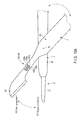
- FIG. 3 is a side view including a partial cross section of a probe
- FIG. 4 is a schematic sectional view showing an inner configuration of a fixed handle
- FIG. 5 is a schematic view showing an electric connection state in a transducer case, a cylindrical member, and an electric connection ring;
- FIG. 6 is a schematic sectional view showing how the probe is inserted into a sheath according to the first embodiment
- FIG. 7 is a sectional view along the VII-VII line shown in FIG. 6 ;
- FIG. 8 is a schematic sectional view showing the configurations of a first slot defining portion and a first protrusion portion of an electric contact unit according to the first embodiment
- FIG. 9 is a schematic sectional view showing the sheath and the jaw in a situation where the jaw is not attached to the sheath according to the first embodiment
- FIG. 10A is a diagram showing a configuration of an acceleration portion according to the first embodiment
- FIG. 10B is a diagram showing a function of the acceleration portion in a grasping operation
- FIG. 10C is a diagram showing a function of the acceleration portion in a peeling operation
- FIG. 11A is a diagram showing a configuration of the acceleration portion according to a first modification of the first embodiment
- FIG. 11B is a diagram showing a configuration of the acceleration portion according to a second modification of the first embodiment
- FIG. 12A is a diagram showing a configuration of the acceleration portion according to a second embodiment
- FIG. 12B is a diagram showing one example of a section of the acceleration portion
- FIG. 12C is a diagram showing one example of the section of the acceleration portion
- FIG. 12D is a diagram showing one example of the section of the acceleration portion
- FIG. 12E is a diagram showing one example of the section of the acceleration portion
- FIG. 12F is a sectional view along the 12 F- 12 F line shown in FIG. 12A ;
- FIG. 13 is a diagram showing a configuration of the acceleration portion according to a third embodiment
- FIG. 14 is a diagram showing a configuration of the acceleration portion according to a fourth embodiment.
- FIG. 15A is a diagram showing one example of a component of the acceleration portion according to a fifth embodiment.
- FIG. 15B is a diagram showing a configuration of the acceleration portion according to the fifth embodiment.
- FIG. 1 The first embodiment is described with reference to FIG. 1 , FIG. 2 , FIG. 3 , FIG. 4 , FIG. 5 , FIG. 6 , FIG. 7 , FIG. 8 , FIG. 9 , FIG. 10A , FIG. 10B , and FIG. 10C .
- some components are not shown for clarification of diagrammatic representation.
- the position of a second electrode portion 53 to a first electrode portion 21 in FIG. 10A is shown upside down compared to the position shown in FIG. 1 for clarification of diagrammatic representation.
- a medical treatment apparatus 1 shown in FIG. 1 sandwiches a treatment object such as a biological tissue to grasp the treatment object by the first electrode portion. 21 located at a distal end portion of a probe 3 and the second electrode portion 53 located at a distal end portion of a later-described jaw 52 which are provided in a later-described energy treatment device (hereinafter, treatment device 10 ). As shown in FIG. 10B , grasping is performed when the second electrode portion 53 is closed (brought close) to the first electrode portion 21 .
- the medical treatment apparatus 1 is capable of treating the grasped treatment target by energy such as ultrasonic waves, high-frequency waves, heat or the like. This medical treatment apparatus 1 is a grasping treatment apparatus.
- the medical treatment apparatus 1 is also used as a bipolar treatment apparatus which conducts a treatment by a high-frequency current by using the distal end portion of the probe 3 and the jaw 52 as electrodes.
- the medical treatment apparatus 1 is also used as an ultrasonic treatment apparatus that treats by ultrasonic vibration.
- the medical treatment apparatus 1 peels off the treatment target by the distal end portion of the probe 3 and the jaw 52 which are pushed into the treatment object. As shown in FIG. 10C , peeling is performed when the second electrode portion 53 opens (comes away) from the first electrode portion 21 .
- the medical treatment apparatus 1 has a power supply unit 7 which functions as a supply unit to supply electric power for energy, and the treatment device 10 which treats the treatment target by energy supplied from the power supply unit 7 .
- the power supply unit 7 has an ultrasonic control unit 8 which controls a current for ultrasonic vibration, and a hi frequency current control unit 9 which controls a current for high-frequency waves.
- the power supply unit 7 further has a cable 6 which is electrically connected to the ultrasonic control unit 8 and the treatment device 10 and which is electrically connected to the high-frequency current control unit 9 and the treatment device 10 .
- One end of the cable 6 is connected to the power supply unit 7 , and the other end of the cable 6 is connected to a proximal end of a later-described transducer case 11 .
- the treatment device 10 has a transducer unit 2 , the probe 3 , a sheath unit 4 , and a movable handle unit 5 .
- the transducer unit 2 , the probe 3 , and the sheath unit 4 are on a fixed side
- the movable handle unit 5 is on a movable side which is rotatably movable to the fixed side.
- the transducer unit 2 has the transducer case 11 . As described above, the proximal end of the transducer case 11 is connected to the end portion of the cable 6 .
- the transducer unit 2 has an ultrasonic transducer 12 which is provided inside the transducer case 11 and which has a piezoelectric element to convert the current supplied from the ultrasonic control unit 8 into ultrasonic vibration.
- the ultrasonic transducer 12 is connected to one end of each of electric signal lines 13 A and 13 B.
- the electric signal lines 13 A and 13 B are provided inside the cable 6 .
- the other end of each of the electric signal lines 13 A and 13 B is connected to the ultrasonic control unit 8 of the power supply unit 7 .
- the ultrasonic transducer 12 is connected to one end of an electric signal line 17 separately from the electric signal lines 13 A and 13 B.
- the electric signal line 17 is provided inside the cable 6 .
- the other end of the electric signal line 17 is connected to the high-frequency current control unit 9 of the power supply unit 7 .
- the electric signal lines 13 A, 13 B, and 17 are included in the cable 6 .
- the transducer unit 2 further has a horn 15 which is coupled to a distal end of the ultrasonic transducer 12 to be located at the distal end of the ultrasonic transducer 12 and which increases the amplitude of the ultrasonic vibration generated in the ultrasonic transducer 12 .
- the horn 15 is attached to the transducer case 11 via an insulating member 15 a .
- the horn 15 is electrically insulated from the transducer case 11 by the insulating member 15 a .
- the horn 15 has an internal thread portion 16 formed at a distal end portion of the horn 15 .
- the probe 3 extends along a longitudinal axis C.
- the probe 3 has a columnar shape.
- the probe 3 has an external thread portion 19 which is formed at a proximal end portion of the probe 3 and which is tightened to the internal thread portion 16 of the horn 15 .
- the probe 3 is attached to the horn 15 by the tightening of the threads.
- the ultrasonic vibration generated in the ultrasonic transducer 12 is transmitted to the distal end of the probe 3 via the horn 15 and the probe 3 . That is, the ultrasonic vibration is transmitted from the proximal end of the probe 3 to its distal end portion.
- the ultrasonic vibration is a vertical vibration in which a transmitting direction of the vibration matches a vibrating direction.
- a probe-side current path of the high-frequency current is formed from the high-frequency current control unit 9 to the distal end portion of the probe 3 through the electric signal line 17 , the ultrasonic transducer 12 , and the horn 15 .
- the probe 3 has the first electrode portion 21 formed at the distal end portion of the probe 3 . That is, the high-frequency current is transmitted by the probe-side current path between the high-frequency current control unit 9 and the first electrode portion 21 along the longitudinal axis C.
- the sheath unit 4 extends along the longitudinal axis C.
- the sheath unit 4 has a fixed handle 22 , and a sheath 23 which is attached to the distal end of the fixed handle 22 .
- the fixed handle 22 has a handle casing 27 which functions as an exterior portion.
- the handle casing 27 has a fixed handle ring 28 which is provided in a part of the handle casing 27 on a later-described second open-close direction side and which functions as a fixed-side finger putting portion.
- the handle casing 27 has a cylindrical member 29 which is provided inside the handle casing 27 and which is fixed to the handle casing 27 .
- the proximal end of the probe 3 extends into the cylindrical member 29 .
- the probe 3 is attached to the horn 15 inside the cylindrical member 29 .
- the cylindrical member 29 supports the probe 3 and the horn 15 via an insulating member 31 .
- the probe 3 and the horn 15 are prevented from coming in contact with the cylindrical member 29 , and the probe 3 and the horn 15 are electrically insulated from the cylindrical member 29 .
- An electric connection ring 32 is provided on an outer circumferential direction side of the cylindrical member 29 .
- the electric connection ring 32 is fixedly provided in the handle casing 27 .
- a distal end portion of the transducer case 11 is engaged in between the cylindrical member 29 and the electric connection ring 32 .
- the distal end portion of the transducer case 11 is engaged in between the cylindrical member 29 and the electric connection ring 32 , whereby the transducer case 11 is coupled to the fixed handle 22 (the sheath unit 4 and the handle casing 27 ).
- the handle casing 27 has an inclined flat plane 33 which is provided in a part on the side of the second open-close direction (the direction of an arrow A 2 shown in FIG. 1 and FIG. 4 ) of the handle casing 27 (the fixed handle 22 ) and which is inclined to the longitudinal axis C.
- This inclined flat plane 33 is provided on a distal end direction side to the fixed handle ring 28 .
- the inclined flat plane 33 is positioned on a proximal end direction side as the inclined flat surface is away from a first direction (a direction of an arrow A 1 shown in FIG. 1 and FIG. 4 ) toward the second direction.
- the inclined flat plane 33 is upwardly inclined from the distal end direction side of the handle casing 27 toward a proximal end direction side.
- the angle between the inclined flat plane 33 and the longitudinal axis C has an acute angle ⁇ .
- the handle casing 27 has input buttons 35 A and 35 B which are two operation input portions provided in the inclined flat plane 33 . If the input buttons 35 A and 35 B are pushed, an operator's operation is input. The press directions of input buttons 35 A and 35 B are perpendicular to the inclined flat plane 33 .
- the handle casing 27 has switch portions 37 A and 37 B and an electric circuit substrate 38 which are provided on an inner circumferential direction side of the inclined flat plane 33 . Opening and closing states of the switch portion 37 A are switched by the input operation in the input button 35 A. Similarly, Opening and closing states of the switch portion 37 B are switched by the input operation in the input button 35 B.
- FIG. 5 is a diagram schematically showing the electric connection state of the transducer case 11 , the cylindrical member 29 , and the electric connection ring 32 .
- the handle casing 27 has three electric signal lines 39 A, 393 , and 39 C which are provided in the handle casing 27 .
- the electric signal line 39 A is electrically connected to the switch portion 37 A via the electric circuit substrate 38 .
- the electric signal line 393 is electrically connected to the switch portion 37 B via the electric circuit substrate 38 .
- the electric signal line 39 C is electrically connected to the switch portion 37 A and the switch portion 37 B via the electric circuit substrate 38 .
- the electric signal line 39 C is a common line shared as a ground line of the switch portion 37 A and the switch portion 37 B.
- the electric connection ring 32 has a first electric connection portion 42 A, a second electric connection portion 42 B, and a third electric connection portion 42 C.
- the first electric connection portion 42 A is electrically insulated from the second electric connection portion 42 B
- the second electric connection portion 42 B is electrically insulated from the third electric connection portion 42 C
- the first electric connection portion 42 A is electrically insulated from the third electric connection portion 42 C.
- the electric signal line 39 A is connected to the first electric connection portion 42 A.
- the electric signal line 39 B is connected to the second electric connection portion 42 B.
- the electric signal line 39 C is connected to the third electric connection portion 42 C.
- the transducer case 11 has a first electrically conductive portion 43 A, a second electrically conductive portion 43 B, and a third electrically conductive portion 43 C.
- the first electrically conductive portion 43 A, the second electrically conductive portion 43 B, and the third electrically conductive portion 43 C extend along the longitudinal axis C.
- the first electrically conductive portion 43 A is electrically insulated from the second electrically conductive portion 43 B
- the second electrically conductive portion 43 B is electrically insulated from the third electrically conductive portion 43 C
- the first electrically conductive portion 43 A is electrically insulated from the third electrically conductive portion 43 C.
- a distal end portion of the first electrically conductive portion 43 A is only in electric contact with the first electric connection portion 42 A of the electric connection ring 32 .
- a distal end portion of the second electrically conductive portion 43 B is only in electric contact with the second electric connection portion 42 B of the electric connection ring 32 .
- a distal end portion of the third electrically conductive portion 43 C is only in electric contact with the third electric connection portion 42 C of the electric connection ring 32 .
- a proximal end portion of the first electrically conductive portion 43 A is connected to one end of an electric signal line 45 .
- a proximal end portion of the second electrically conductive portion 43 B is connected to one end of an electric signal line 46 .
- a proximal end portion of the third electrically conductive portion 43 C is connected to one end of an electric signal line 47 .
- the electric signal lines 45 , 46 , and 47 are provided inside the cable 6 .
- the other ends of the electric signal lines 45 , 46 , and 47 are connected to the power supply unit 7 .
- a first electric signal path is formed from the switch portion 37 A to the power supply unit 7 through the electric signal line 39 A, the first electric connection portion 42 A, the first electrically conductive portion 43 A, and the electric signal line 45 .
- a second electric signal path is formed from the switch portion 37 B to the power supply unit 7 through the electric signal line 39 B, the second electric connection portion 42 B, the second electrically conductive portion 43 B, and the electric signal line 46 .
- a ground path is formed from the switch portion 37 A and the switch portion 37 B to the power supply unit 7 through the electric signal line 39 C, the third electric connection portion 42 C, the third electrically conductive portion 43 C, and the electric signal line 47 .
- the switch portion 37 A is a closed state, and the first electric signal path is electrically connected to the ground path by the switch portion 37 A.
- an electric signal is transmitted to the power supply unit 7 from the switch portion 37 A.
- the state is then switched so that a current is supplied to the ultrasonic transducer 12 from the ultrasonic control unit 8 via the electric signal lines 13 A and 13 B, ultrasonic vibration is generated in the ultrasonic transducer 12 , and the high-frequency current is output from the high-frequency current control unit 9 at the same time.
- the switch portion 37 B is a closed state, and the second electric signal path is electrically connected to the ground path by the switch portion 37 B.
- an electric signal is transmitted to the power supply unit 7 from the switch portion 37 B.
- the state is then switched so that the high-frequency current is output from the high-frequency current control unit 9 alone, and no ultrasonic vibration is generated.
- the transducer case 11 further has a fourth electrically conductive portion 43 D which extends along the longitudinal axis C.
- the first electrically conductive portion 43 A, the second electrically conductive portion 43 B, and the third electrically conductive portion 43 C are all electrically insulated from the fourth electrically conductive portion 43 D.
- a proximal end portion of the fourth electrically conductive portion 43 D is connected to one end of an electric signal line 48 .
- the electric signal line 48 is provided inside the cable 6 .
- the other end of the electric signal line 48 is connected to the high-frequency current control unit 9 of the power supply unit 7 .
- a distal end portion of the fourth electrically conductive portion 43 D is only in electric contact with the cylindrical member 29 .
- the cylindrical member 29 is connected to one end of an electric signal line 49 .
- the other end of the electric signal line 49 is connected to the sheath 23 .
- the high-frequency current is transmitted between the high-frequency current control unit 9 and the sheath 23 via the electric signal line 48 , the fourth electrically conductive portion 43 D, the cylindrical member 29 , and the electric signal line 49 .
- the sheath 23 is provided on the outer circumferential direction side to the probe 3 .
- the probe 3 is inserted into the sheath 23 so that the first electrode portion 21 which functions as the distal end portion of the probe 3 protrudes from a distal end of the sheath 23 .
- the sheath 23 has a support member 51 which is provided between the probe 3 and the sheath 23 in a radial direction of the sheath 23 and which supports the probe 3 .
- the support member 51 is made of an insulating material.
- the support member 51 prevents the contact between the probe 3 and the sheath 23 , and electrically insulates the probe 3 from the sheath 23 .
- the support member 51 is disposed at the node position of ultrasonic vibration. This more effectively prevents the contact between the probe 3 and the sheath 23 .
- One or more support members 51 may be provided, and at least one support member 51 has only to be provided.
- the movable handle unit 5 can open and close to the fixed side including the probe 3 and the sheath unit 4 for a treatment operation to treat the treatment target.
- the movable handle unit 5 has a movable handle 25 which is provided in a proximal end portion of the movable handle unit and which functions as a force application point in the treatment operation.
- the movable handle 25 can open and close to the fixed handle 22 around a later-described rotation axis R as a center which perpendicular to the longitudinal axis C in an open-close direction along the circumference of the rotation axis.
- the movable handle 25 has a movable handle ring 26 which functions as a movable-side finger placing portion.
- the movable handle 25 can open and close to the fixed handle 22 in a first open-close direction (first direction) perpendicular to the longitudinal axis C indicated in the arrow A 1 direction in FIG. 1 , and in a second open-close direction (second direction) which is a direction opposite to the first open-close direction indicated in the arrow A 2 direction in FIG. 1 .
- the movable handle 25 is located closer to the first open-close direction side to the fixed handle 22 .
- An axis L 1 of the movable handle 25 is inclined to have an acute angle ⁇ with the longitudinal axis C.
- the movable handle unit 5 further has the jaw 52 which is rotatably attached to the distal end portion of the sheath 23 , and an relay member 57 provided between the movable handle 25 and the jaw 52 .
- the movable handle unit 5 is coupled to the sheath unit 4 .
- the jaw 52 has the second electrode portion 53 which is provided in a distal end portion of the movable handle unit 5 and which functions as a jaw distal end portion that functions as an action point in the treatment operation.
- the jaw 52 is attached to the distal end portion of the sheath 23 so that the jaw 52 is rotatable around the rotation axis R as the center.
- the jaw 52 rotates around the rotation axis R as the center in accordance with the opening and closing of the movable handle 25 and can thereby open and close in an open-close direction which intersects with, more specifically, is perpendicular to the longitudinal axis direction and the rotation axis direction to the first electrode portion 21 which functions as the distal end portion of the probe 3 .
- the jaw 52 can open and close to the first electrode portion 21 which is provided at the distal end portion of the probe 3 .
- the jaw 52 has the second electrode portion 53 which is located on a second open-close direction (the direction of the arrow A 2 shown in FIG. 1 and FIG. 6 ) to the first electrode portion 21 of the probe 3 .
- the second electrode portion 53 is electrically connected to the sheath 23 .
- the second electrode portion 53 has a probe facing portion 55 which is provided in a part of an outer surface of the second electrode portion 53 (jaw 52 ) on the first open-close direction (the direction of an arrow A 1 shown in FIG. 1 and FIG. 6 ) side and which faces the first electrode portion 21 .
- the first electrode portion 21 has a jaw facing portion 58 which is provided in a part of an outer surface of the first electrode portion 21 on the second open-close direction (the direction of an arrow A 2 shown in FIG. 1 and FIG. 6 ) side and which faces the second electrode portion 53 .
- the movable handle unit 5 has the rotation axis R which is provided at a coupling portion of the movable handle unit 5 and the sheath 23 and which functions as a rotation center.
- the rotation axis R intersects with the longitudinal axis C, and is provided perpendicularly to the longitudinal axis C and perpendicularly to the first open-close direction and the second open-close direction.
- the movable handle unit 5 rotates around this rotation axis.
- the movable handle 25 moves in the first open-close direction, and the movable handle 25 performs an opening operation to the fixed handle 22 , whereby the jaw 52 moves in the second open-close direction. In consequence, the jaw 52 is at an opening position to the first electrode portion 21 .
- the movable handle 25 moves in the second open-close direction, and the movable handle 25 performs a closing operation to the fixed handle 22 , whereby the jaw 52 moves in the first open-close direction. In consequence, the jaw 52 is at a closing position to the first electrode portion 21 .
- the jaw 52 performs the open-close operations to the first electrode portion 21 to the opening position and the closing position by rotating to the sheath 23 around the rotation axis R as the center.
- the second electrode portion 53 is electrically connected to the sheath 23 .
- the high-frequency current is transmitted between the sheath 23 and the second electrode portion 53 .
- the high-frequency current is transmitted between the high-frequency current control unit 9 and the sheath 23 via the electric signal line 48 , the fourth electrically conductive portion 43 D, and the electric signal line 49 . Therefore, a jaw-side current path is formed from the high-frequency current control unit 9 to the second electrode portion 53 of the jaw 52 through the electric signal line 48 , the fourth electrically conductive portion 43 D, the electric signal line 49 , and the sheath 23 . That is, the high-frequency current is transmitted between the high-frequency current control unit 9 and the second electrode portion 53 by the jaw-side current path.
- An outer surface of the sheath 23 and an outer surface of a part of the jaw 52 other than the probe facing portion 55 are, for example, coated for insulation. This prevents an electric shock even when, for example, the hand of the operator has touched the outer surface of the sheath 23 or the outer surface of the jaw 52 .
- the relay member 57 provided between the jaw 52 and the movable handle 25 is made of an insulating material. This prevents the transmission of the high-frequency current from the jaw 52 to the movable handle 25 .
- the treatment device 10 further has an electric contact unit 60 which is provided between the sheath 23 and the jaw 52 and which holds the state in which the high-frequency current is always transmitted between the sheath 23 and the second electrode portion 53 of the jaw 52 .
- This electric contact unit 60 functions as a coupling portion to couple the sheath 23 with the jaw 52 to rotate the jaw 52 to the sheath 23 around the rotation axis R as the center.
- the electric contact unit 60 has a first slot portion 61 A and a second slot portion 61 B which are depressed in the jaw 52 along the rotation axis R in the outer circumferential direction.
- the first slot portion 61 A is depressed in a first rotation axis direction (the direction of an arrow B 1 shown in FIG.
- the second slot portion 61 B is depressed in a second rotation axis direction (the direction of an arrow B 2 shown in FIG. 7 ) which is a direction opposite to the first rotation axis direction.
- the first slot portion 61 A is defined by a first slot defining portion 62 A
- the second slot portion 61 B is defined by a second slot defining portion 62 B.
- the electric contact unit 60 has a first protrusion portion 63 A and a second protrusion portion 63 B which protrude in the outer circumferential direction along the rotation axis R in an outer circumferential portion of the sheath 23 .
- the first protrusion portion 63 A protrudes in the first rotation axis direction
- the second protrusion portion 63 B protrudes in the second rotation axis direction.
- the first protrusion portion 63 A is inserted to the first slot portion 61 A
- the second protrusion portion 63 B is inserted to the second slot portion 61 B.
- FIG. 8 is a diagram showing the configurations of the first slot defining portion 62 A and the first protrusion portion 63 A. Although only the first slot defining portion 62 A and the first protrusion portion 63 A are described below, the configuration of the second slot defining portion 62 B is similar to the configuration of the first slot defining portion 62 A, and the configuration of the second protrusion portion 63 B is similar to the configuration of the first protrusion portion 63 A. Therefore, the second slot defining portion 62 B and the second protrusion portion 63 B are not described.
- the first slot defining portion 62 A has a slot side surface 65 and a slot bottom surface 67 .
- the first protrusion portion 63 A has a protruding end 69 .
- the first protrusion portion 63 A is inserted to the first slot portion 61 A with a space portion between the first protrusion portion 63 A and the slot side surface 65 .
- a sheath-side contact portion 71 is located at the protruding end 69 . That is, the sheath-side contact portion 71 is provided in the outer circumferential portion of the sheath 23 .
- a jaw-side contact portion 73 is located on the slot bottom surface 67 of the first slot defining portion 62 A of the jaw 52 .
- the jaw-side contact portion 73 is provided in an inner circumferential portion of the jaw 52 .
- the jaw-side contact portion 73 slidably contacts the sheath-side contact portion 71 .
- a high-frequency current is transmitted between the sheath 23 and the second electrode portion 53 of the jaw 52 by the contact between the jaw-side contact portion 73 and the sheath-side contact portion 71 .
- FIG. 9 is a diagram showing the sheath 23 and the jaw 52 in a situation where the jaw 52 is not attached to the sheath 23 .
- a first dimension T 1 from the longitudinal axis C to the sheath-side contact portion 71 along the rotation axis R is greater than a second dimension T 2 from the longitudinal axis C to the jaw-side contact portion 73 along the rotation axis R.
- the contact between the jaw-side contact portion 73 and the sheath-side contact portion 71 is always maintained even when the space portion is provided between the first protrusion portion 63 A and the slot side surface 65 of the first slot defining portion 62 A. Therefore, the situation where the high-frequency current is transmitted between the sheath 23 and the second electrode portion 53 of the jaw 52 is maintained.
- the first protrusion portion 63 A comprises a protrusion portion-side semispherical portion 75 which is semispherically provided up to the sheath-side contact portion 71 along the rotation axis R.
- the protrusion portion-side semispherical portion 75 is a protrusion portion-side section changing portion which decreases in sectional area perpendicular to the rotation axis R toward the protruding end 69 of the first protrusion portion 63 A along the rotation axis R.
- the contact area of the sheath-side contact portion 71 and the jaw-side contact portion 73 is reduced by the protrusion portion-side semispherical portion 75 .
- Acceleration Portion 100 [Elastic Deformation Acceleration Portion (Hereinafter, Acceleration Portion 100 )]
- the treatment device 10 further has an acceleration portion 100 provided in, for example, the movable handle unit 5 which is on the movable side.
- the acceleration portion 100 accelerates the elastic deformation of the movable handle unit 5 in a direction in which the movable handle unit 5 has received the reaction force F.
- the acceleration portion 100 accelerates the elastic deformation of the movable handle unit 5 to the side opposite to the direction in which the movable handle unit 5 has received the reaction force F so that the movable handle unit 5 is restored to the original state showing the state before the start of the treatment operation.
- the acceleration portion 100 is provided closer to the side of the second electrode portion 53 provided in the distal end portion side of the jaw 52 which functions as the action point in the treatment operation to the side of the movable handle 25 which functions as the force application point in the treatment operation.
- the acceleration portion 100 is preferably provided, in the axial direction of the movable handle unit 5 , between the second electrode portion 53 provided at the distal end portion of the jaw 52 which functions as the action point in the treatment operation and the rotation axis R which functions as a supporting point in the treatment operation.
- the reaction force F is applied the most to a part between the second electrode portion 53 which functions as the action point and the rotation axis R which functions as a supporting point in the axial direction of the movable handle unit 5 .
- the reaction force F is applied more to the rotation axis R side to the second electrode portion 53 side.
- the most load is applied to the rotation axis R side, and the rotation axis R side needs to divert the load.
- the acceleration portion 100 is particularly preferably provided in the axial direction of the movable handle unit 5 , closer to the rotation axis R side which functions as a supporting point in the treatment operation to the second electrode portion 53 side provided in the distal end portion side of the jaw 52 which functions as the action point in the treatment operation.
- this acceleration portion 100 is provided, for example, in one part of the jaw 52 located between a proximal end portion of the second electrode portion 53 and the rotation axis R in the axial direction of the movable handle unit 5 .
- the acceleration portion 100 is formed by the deformation of one part of the jaw 52 , is included in the jaw 52 , and is integral with the jaw 52 .
- the second electrode portion 53 receives the reaction force F from the treatment target 150 in a direction opposite to the close direction, that is, in the open direction (the arrow A 2 direction).
- the acceleration portion 100 accelerates the elastic deformation of the jaw 52 so that the jaw 52 is elastically deformed around the acceleration portion 100 in the open direction.
- the acceleration portion 100 accelerates the elastic deformation of the jaw 52 so that the second electrode portion 53 warps (flexes) around the acceleration portion 100 in the jaw 52 in the open direction, the second electrode portion 53 moves away from the first electrode portion 21 , the jaw 52 changes from the straight state to the bent state, and the jaw 52 diverts the reaction force F.
- the acceleration portion 100 accelerates the elastic deformation of the jaw 52 so that the jaw 52 is restored to the original state, that is, the second electrode portion 53 warps (flexes) around the acceleration portion 100 in the jaw 52 in the close direction (the arrow A 1 direction), the second electrode portion 53 moves closer to the first electrode portion 21 , and the jaw 52 changes from the bent state to the straight state.
- the second electrode portion 53 receives the reaction force F from the treatment target 150 in a direction opposite to the open direction, that is, in the close direction (the arrow A 1 direction).
- the acceleration portion 100 accelerates the elastic deformation of the jaw 52 so that the jaw 52 is elastically deformed around the acceleration portion 100 in the close direction.
- the acceleration portion 100 accelerates the elastic deformation of the jaw 52 so that the second electrode portion 53 warps (flexes) around the acceleration portion 100 in the jaw 52 in the close direction, the second electrode portion 53 moves closer to the first electrode portion 21 , the jaw 52 changes from the straight state to the bent state, and the jaw 52 diverts the reaction force F.
- the acceleration portion 100 accelerates the elastic deformation of the jaw 52 so that the jaw 52 is restored to the original state, that is, the second electrode portion 53 warps (flexes) around the acceleration portion 100 in the jaw 52 in the open direction (the arrow A 2 direction), the second electrode portion 53 moves away from the first electrode portion 21 , and the jaw 52 changes from the bent state to the straight state.
- the second electrode portion 53 receives the reaction force F from the treatment target 150 in a direction opposite to the open-close direction, that is, in the close-open direction (the arrow A 2 direction or the arrow A 1 direction).
- the acceleration portion 100 accelerates the elastic deformation of the jaw 52 so that the jaw 52 is elastically deformed in the direction in which the jaw 52 has received the reaction force F.
- the acceleration portion 100 accelerates the elastic deformation of the jaw 52 so that the second electrode portion 53 warps (flexes) around the acceleration portion 100 in the jaw 52 in the direction in which the jaw 52 has received the reaction force F and the jaw 52 diverts the reaction force F.
- the acceleration portion 100 accelerates the elastic deformation of the jaw 52 so that the jaw 52 is elastically deformed in a direction opposite to the direction in which the jaw 52 has received the reaction force F.
- the acceleration portion 100 accelerates the elastic deformation of the jaw 52 so that the second electrode portion 53 warps (flexes) around the acceleration portion 100 in the jaw 52 in the direction opposite to the direction in which the jaw 52 has received the reaction force F and the jaw 52 changes from the bent state to the straight state.
- the acceleration portion 100 has a thickness-reduced portion 101 which is easily elastically deformed so that the jaw 52 is easily elastically deformed.
- the thickness-reduced portion 101 is formed by reducing the thickness of the jaw 52 in the acceleration portion 100 in comparison with the thickness of the jaw 52 in parts other than the acceleration portion 100 so that the jaw 52 is elastically deformed around the acceleration portion 100 .
- the thickness of the jaw 52 in the thickness-reduced portion 101 has only to be reduced in comparison with the thickness of the jaw 52 around the thickness-reduced portion 101 other than the thickness-reduced portion 101 .
- the part around the thickness-reduced portion 101 represents, for example, the jaw 52 between the rotation axis R and the acceleration portion 100 , and the jaw 52 between the second electrode portion 53 side which functions as the action point and the acceleration portion 100 .
- the thickness-reduced portion 101 is directly provided, for example, in one part of the jaw 52 .
- the thickness-reduced portion 101 is provided to function as a detour portion in which one part of the jaw 52 is corrugated along a central axis direction of the jaw 52 .
- one part of the jaw 52 in the detour portion is thinner than the other parts of the jaw 52 .
- the maximum thickness of one part of the jaw 52 in the detour portion is substantially the same as the maximum thickness of the other parts of the jaw 52 .
- the thickness-reduced portion 101 has open-side slots 103 a which are depressed from an open-direction-side end face of the jaw 52 toward a close-direction-side end face of the jaw 52 , and close-side slots 103 b which are depressed from the close-direction-side end face toward the open-direction-side end face.
- the open-direction-side end face is, for example, a front surface of the jaw 52
- the close-direction-side end face is, for example, a rear surface of the jaw 52 .
- the open-direction-side end face does not contact the treatment target 150 during the grasping operation, and contacts the treatment target 150 during the peeling operation.
- the close-direction-side end face contacts the treatment target 150 during the grasping operation, and does not contact the treatment target 150 during the peeling operation.
- the open-side slots 103 a and the close-side slots 103 b are alternately provided in the central axis direction of the jaw 52 .
- the number of the open-side slots 103 a is preferably the same as the number of the close-side slots 103 b .
- the depth of the open-side slot 103 a is preferably the same as the depth of the close-side slot 103 b .
- the length of the open-side slot 103 a is preferably the same as the length of the close-side slot 103 b .
- the open-side slots 103 a and the close-side slots 103 b are provided to intersect at right angle with the central axis direction of the jaw 52 , and are provided along a thickness direction of the jaw 2 .
- the open-side slots 103 a and the close-side slots 103 b pass through the jaw 52 in a width direction of the jaw 52 .
- the open-side slots 103 a and the close-side slots 103 b function as slits.
- the thickness-reduced portion 101 has open-side thin portions 105 a which are formed by providing the close-side slots 103 b and which are provided on the open-direction-side end face side of the jaw 52 , and close-side thin portions 105 b which are formed by providing the open-side slots 103 a and which are provided on the close-direction-side end face side of the jaw 52 .
- the open-side thin portions 105 a and the close-side thin portions 105 b are alternately provided in the central axis direction of the jaw 52 .
- the open-side thin portions 105 a are provided, for example, higher than the central axis of the jaw 52 in the thickness direction of the jaw 52 .
- the close-side thin portions 105 b are provided, for example, lower than the central axis of the jaw 52 in the thickness direction of the jaw 52 .
- the open-side thin portions 105 a and the close-side thin portions 105 b are formed by reducing the thickness of one part of the jaw 52 in comparison with the maximum thickness of the jaw 52 , so that the jaw 52 is locally reduced in thickness.
- the width in the open-side thin portions 105 a and the close-side thin portions 105 b is equal to the width in the other parts of the jaw 52 .
- the close-side slot 103 b is provided in alignment with the open-side thin portion 105 a to face the open-side thin portion 105 a in the thickness direction of the jaw 52 that intersects at right angles with the central axis of the jaw 52 .
- the open-side slot 103 a is provided in alignment with the close-side thin portion 105 b to face the close-side thin portion 105 b in the thickness direction of the jaw 52 .
- the thickness-reduced portion 101 further has thick portions 107 a which are contiguous to the open-side thin portions 105 a and the close-side thin portions 105 b and which have the same thickness as the other parts of the jaw 52 .
- the thick portions 107 a are provided along the thickness direction of the jaw 52 .
- the open-side slot 103 a and the close-side thin portion 105 b , the thick portion 107 a , the close-side slot 103 b and the open-side thin portion 105 a , the thick portion 107 a , the open-side slot 103 a and the close-side thin portions 105 b , the thick portion 107 a , . . . are arranged in this order.
- the respective units are not particularly limited in number.
- This acceleration portion 100 also functions as a local sectional portion which is a local reduction of the section of the jaw 52 .
- the acceleration portion 100 varies the rigidity of one part of the jaw 52 in comparison with the rigidity of the other parts by the open-side slots 103 a and the close-side slots 103 b so that the rigidity of one part of the jaw 52 is lower than the rigidity of the other parts.
- the second electrode portion 53 and the first electrode portion 21 grasp and sandwich the treatment target 150 therebetween together.
- the second electrode portion 53 receives the reaction force F from the treatment target 150 in the open direction (the arrow A 2 direction).
- the jaw 52 is then elastically deformed around the acceleration portion 100 in the open direction. At the same time, the elastic deformation is accelerated by the acceleration portion 100 .
- the acceleration portion 100 accelerates the elastic deformation of the jaw 52 so that the second electrode portion 53 warps (flexes) around the acceleration portion 100 in the jaw 52 in the open direction, the second electrode portion 53 moves away from the first electrode portion 21 , and the jaw 52 changes from the straight state to the bent state.
- the elastic deformation accelerated by the acceleration portion 100 ensures that the jaw 52 can divert the reaction force F. Therefore, the jaw 52 is prevented gradual deformation of the jaw 52 by the reaction force F which the jaw 52 receives from the treatment target 150 .
- the second electrode portion 53 can also abut on the treatment target 150 along a circumferential surface of the treatment target 150 because the jaw 52 is elastically deformed. Thus, a grasping force can also be improved.
- the close-side slots 103 b expand, and the open-side slots 103 a narrow so that edges of the open-side slots 103 a abut on each other, in the central axis direction of the jaw 52 (the length of the close-side slots 103 b ).
- the abutment of the edges of the open-side slots 103 a prevents the jaw 52 from being extremely elastically deformed in the open direction, i.e., from bending around the acceleration portion 100 .
- the movable handle 25 is opened to the fixed handle 22 , the jaw 52 is opened to the probe 3 , the second electrode portion 53 moves away from the treatment target 150 , and the reaction force F is no longer applied to the second electrode portion 53 .
- the jaw 52 is then elastically deformed around the acceleration portion 100 in the close direction. At the same time, the elastic deformation is accelerated by the acceleration portion 100 .
- the acceleration portion 100 accelerates the elastic deformation of the jaw 52 so that the jaw 52 is restored to the original state, the second electrode portion 53 warps (flexes) around the acceleration portion 100 in the jaw 52 in the close direction, the second electrode portion 53 moves closer to the first electrode portion 21 , and the jaw 52 changes from the bent state to the straight state.
- the close amount in which the operator closes the movable handle 25 to the fixed handle 22 varies.
- grasping force E 1 before deformation may not be obtained even if the operator closes the movable handle 25 to the fixed handle 22 in a close amount A 1 before deformation during the grasping operation.
- the second electrode portion 53 and the first electrode portion 21 peel the treatment target 150 together.
- the second electrode portion 53 receives the reaction force F from the treatment target. 150 in the close direction (the arrow A 1 direction).
- the jaw 52 is elastically deformed around the acceleration portion 100 in the close direction.
- the elastic deformation is accelerated by the acceleration portion 100 .
- the acceleration portion 100 accelerates the elastic deformation of the jaw 52 so that the second electrode portion 53 warps (flexes) around the acceleration portion 100 in the jaw 52 in the close direction, the second electrode portion 53 moves closer to the first electrode portion 21 , and the jaw 52 changes from the straight state to the bent state.
- the elastic deformation accelerated by the acceleration portion 100 ensures that the jaw 52 can divert the reaction force F. Therefore, the jaw 52 is prevented gradual deformation of the jaw 52 by the reaction force F which the jaw 52 receives from the treatment target 150 .
- the second electrode portion 53 can also abut on the treatment target 150 along the circumferential surface of the treatment target 150 because the jaw 52 is elastically deformed. Thus, a peeling force can also be improved.
- the open-side slots 103 a expand, and the close-side slots 103 b narrow so that edges of the close-side slots 103 b abut on each other, in the central axis direction of the jaw 52 (the length of the close-side slots 103 b ).
- the abutment of the edges of the close-side slots 103 b prevents the jaw 52 from being extremely elastically deformed in the close direction, i.e., from bending around the acceleration portion 100 .
- the movable handle 25 is closed to the fixed handle 22 , the jaw 52 is closed to the probe 3 , the second electrode portion 53 moves away from the treatment target 150 , and the reaction force F is no longer applied to the second electrode portion 53 .
- the jaw 52 is then elastically deformed around the acceleration portion 100 in the open direction. At the same time, the elastic deformation is accelerated by the acceleration portion 100 .
- the acceleration portion 100 accelerates the elastic deformation of the jaw 52 so that the jaw 52 is restored to the original state, the second electrode portion 53 warps (flexes) around the acceleration portion 100 in the jaw 52 in the open direction, the second electrode portion 53 moves away from the first electrode portion 21 , and the jaw 52 changes from the bent state to the straight state.
- the open amount in which the operator opens the movable handle 25 to the fixed handle 22 varies.
- the jaw 52 or the like is not restored to the original state from the deformed state during the peeling operation, there is concern that peeling force B 1 before deformation may not be obtained even if the operator opens the movable handle 25 to the fixed handle 22 in an open amount A 1 before deformation during the peeling operation.
- peeling operability may gradually deteriorate because of the absence of the recovery from the deformed state to the original state during the peeling operation.
- the jaw 52 can be elastically deformed by the acceleration portion 100 . Therefore, even if the second electrode portion 53 receives the reaction force F from the treatment target 150 during a treatment operation such as the grasping operation and the peeling operation, the jaw 52 can divert the reaction force F in the direction in which the jaw 52 has received the reaction force F. This prevents the jaw 52 from being gradually deformed by the reaction force F from the treatment target 150 . It is ensured that if the treatment operation has finished, the jaw 52 can be restored to the straight state which is the original state. When the treatment operation is started again, the jaw 52 comes into the straight state which is the above-mentioned initial state, and the first electrode portion 21 and the second electrode portion 53 can grasp the treatment target 150 together in this initial state.
- the deformation of the jam 52 can be prevented by the acceleration portion 100 , and gradual deterioration of a treatment force such as the grasping force and the peeling force can be prevented.
- a treatment force such as the grasping force and the peeling force
- the jaw 52 can be elastically deformed by the acceleration portion 100 . Therefore, in a treatment operation such as the grasping operation and the peeling operation, the second electrode portion 53 can abut on the treatment target 150 along the circumferential surface of the treatment target 150 .
- the treatment force such as the grasping force and the peeling force can also be improved.
- the reaction force F is applied the most to the part between the second electrode portion 53 side which functions as the action point and the rotation axis R side which functions as the supporting point in the axial direction of the movable handle unit 5 .
- the reaction force F is applied more to the rotation axis R side than to the second electrode portion 53 side.
- the acceleration portion 100 is provided closer to the rotation axis R side to the second electrode portion 53 side.
- the elastic deformation of the jaw 52 in this part can be accelerated, the jaw 52 can effectively divert the reaction force F, and the load on the jaw 52 can be reduced.
- the acceleration portion 100 has the thickness-reduced portion 101 (a part of the jaw 52 which functions as the detour portion).
- the deformation of the jaw 52 can be prevented by the thickness-reduced portion 101 , and gradual deterioration of the treatment force such as the grasping force and the peeling force can be prevented. Therefore, in the present embodiment, resulting gradual deterioration of treatment operability can be prevented.
- the acceleration portion 100 has the open-side slots 103 a and the close-side slots 103 b which are depressed in the open-close direction of the jaw 52 .
- the acceleration portion 100 can accelerate the elastic deformation of the jaw 52 so that the jaw 52 is elastically deformed in the direction in which the jaw 52 has received the reaction force F during the treatment operation. If the treatment operation has finished, the acceleration portion 100 can accelerate the elastic deformation of the jaw 52 so that the jaw 52 is elastically deformed in a direction opposite to the direction in which the jaw 52 has received the reaction force F.
- the acceleration portion 100 accelerates the elastic deformation of the jaw 52 so that direct transmission of an open-close force to the treatment target 150 via the second electrode portion 53 can be prevented.
- the acceleration portion 100 can prevent the open-close force from being directly transmitted to the treatment target 150 and excessively damaging the treatment target 150 .
- the acceleration portion 100 may only have the close-side slots 103 b , the open-side thin portions 105 a , and the thick portions 107 a .
- Multiple close-side slots 103 b , multiple open-side thin portions 105 a , and multiple thick portions 107 a are provided.
- the close-side slots 103 b are provided at equal distance from one another in the central axis direction of the jaw 52 .
- the close-side slot 103 b and the open-side thin portion 105 a , the thick portion 107 a , the close-side slot 103 b and the open-side thin portion 105 a , the thick portion 107 a , the close-side slot 103 b and the open-side thin portion 105 a , . . . are arranged in this order.
- the respective units are not particularly limited in number.
- an elastic deformation force representing a warping force in the grasping operation is different from an elastic deformation force representing a warping force in the peeling operation, and greater than the elastic deformation force in the peeling operation.
- An elastic deformation force representing a warping force when the grasping operation has finished is different from an elastic deformation force representing a warping force when the peeling operation has finished, and greater than the elastic deformation force in the peeling operation.
- elastic deformation can be varied in the treatment operation, and a configuration specialized for the grasping operation can be provided.
- the acceleration portion 100 may only have the open-side slots 103 a , the close-side thin portions 105 b , and the thick portions 107 a .
- Multiple open-side slots 103 a , multiple close-side thin portions 105 b , and multiple thick portions 107 a are provided.
- the open-side slots 103 a are provided at equal distance from one another in the central axis direction of the jaw 52 .
- the open-side slot 103 a and the close-side thin portion 105 b , the thick portion 107 a , the open-side slot 103 a and the close-side thin portion 105 b , the thick portion 107 a , . . . are arranged in this order.
- the respective units are not particularly limited in number.
- an elastic deformation force representing a warping force in the grasping operation is different from an elastic deformation force representing a warping force in the peeling operation, and smaller than the elastic deformation force in the peeling operation.
- An elastic deformation force representing a warping force when the grasping operation has finished is different from an elastic deformation force representing a warping force when the peeling operation has finished, and smaller than the elastic deformation force in the peeling operation.
- elastic deformation can be varied in the treatment operation, and a configuration specialized for the peeling operation can be provided.
- the acceleration portion 100 has only to have at least one of the close-side slot 103 b and the open-side slot 103 a.
- Multiple acceleration portions 100 may be discontinuously provided in the central axis direction of the jaw 52 .
- FIG. 12A , FIG. 12B , FIG. 12C , FIG. 12D , FIG. 12E , and FIG. 12F The differences between the first embodiment and the second embodiment are only described below with reference to FIG. 12A , FIG. 12B , FIG. 12C , FIG. 12D , FIG. 12E , and FIG. 12F .
- the thickness-reduced portion. 101 is provided so that one part of the jaw 52 is formed to be thinner and flatter than the other parts of the jaw 52 in the open-close direction of the jaw 52 .
- a central axis of the thickness-reduced portion 101 is coaxial with the central axis of the whole jaw 52 .
- the section of the thickness-reduced portion 101 that intersects at right angles with the central axis of the jaw 52 has a symmetrical shape with respect to the central axis of the thickness-reduced portion 101 in a thickness direction of the thickness-reduced portion 101 which is the open-close direction.
- the section has, for example, one of a rectangular shape shown in FIG. 12B and FIG. 12F , a trapezoidal shape shown in FIG. 12C and FIG. 12D , and an elliptical shape shown in FIG. 12E .
- an upper side may be shorter than a lower side as shown in FIG. 12C , or the upper side may be longer than the lower side as shown in FIG. 12D .
- the section has an upper surface which functions as the open-direction-side end face of the jaw 52 , and a lower surface which functions as the close-direction-side end face of the jaw 52 .
- the upper surface and the lower surface are flat surfaces.
- W is the width of the section which is the length of the upper side and the lower side
- the height of the section is H.
- the above-mentioned thickness-reduced portion 101 also functions as a small diameter portion in which one part of the jaw 52 is thinner than the other parts of the jaw 52 .
- the configuration of the acceleration portion 100 can be simpler, and the acceleration portion 100 can be easily formed.
- the central axis of the thickness-reduced portion 101 is parallel to the central axis of the whole jaw 52 , and the section has a symmetrical shape. This ensures that, for example, same warping amount (flexing amount) in the grasping operation and the peeling operation can be obtained, the warping amount is the elastic deformation amount, and, for example, same return amount when the grasping operation has finished and when the peeling operation has finished can be obtained, the return amount is the elastic deformation amount.
- Multiple acceleration portions 100 may be provided in the central axis direction of the jaw 52 . In this case, it is preferable that the acceleration portions 100 are provided at equal distance from one another in the central axis direction of the jaw 52 .
- the thickness-reduced portion 101 is provided so that one part of the jaw 52 functions as the detour portion which is corrugated along a direction that intersects at right angles with the central axis direction of the jaw 52 .
- the open-side slot 103 a and the close-side slot 103 b are, for example, L-shaped.
- the open-side thin portion 105 a and the close-side thin portion 105 b are, for example, L-shaped.
- one side of the L-shape is provided to intersect at right angles with the central axis direction of the jaw 52 , and the other side of the L-shape is provided along the central axis direction of the jaw 52 .
- one side of the L-shape is provided to intersect at right angles with the central axis direction of the jaw 52 , and the other side of the L-shape is provided along the central axis direction of the jaw 52 .
- the other sides of the L-shapes are adjacently provided in a direction that intersects at right angles with the central axis direction of the jaw 52 .
- the thickness-reduced portion 101 further has a thickness portion 107 b which is contiguous to the open-side thin portion 105 a and the close-side thin portion 105 b and which is provided along the central axis direction of the jaw 52 .
- the acceleration portion 100 may be provided in the second electrode portion 53 which functions as the distal end portion of the jaw 52 .
- the acceleration portion 100 has a cutout portion 109 which is provided along the central axis direction of the jaw 52 and which is formed by cutting out one part of the distal end portion of the jaw 52 .
- the cutout portion 109 is provided at the proximal end portion of the second electrode portion 53 which is a fundamental part of the distal end portion of the jaw 52 .
- the acceleration portions 100 are provided at the distal end portion of the jaw 52 and in the jaw 52 , so that two elastically deformable parts are provided. This ensures that the deformation of the jaw 52 can be prevented by the acceleration portion 100 and that gradual deterioration of the operational force such as the grasping force and the peeling force can be prevented even if the treatment operation is repeated in the present embodiment. Therefore, in the present embodiment, gradual deterioration of operability can be prevented.
- the second electrode portion 53 can abut on the treatment target along the circumferential surface of the treatment target.
- the cutout portion 109 accelerates the elastic deformation of the second electrode portion 53
- the thickness-reduced portion 101 accelerates the elastic deformation of the jaw 52 .
- the load on the jaw 52 can be further reduced in the grasping operation.
- the thickness the acceleration portion 100 may be varied in the central axis direction of the jaw 52 so that the thickness increases from the distal end portion of the acceleration portion 100 toward the proximal end portion of the acceleration portion 100 .
- the elastic deformation amount can be adjusted.
- the depth of one open-side slot 103 a may be varied so that the distal end portion side of the open-side slot 103 a is shallower and the proximal end portion side of the open-side slot 103 a is deeper in the central axis direction of the jaw 52 .
- the depths of the open-side slots 103 a may be varied so that the open-side slots 103 a provided on the distal end portion side of the acceleration portion 100 are shallower and the open-side slots 103 a provided on the proximal end portion side of the acceleration portion 100 are deeper in the central axis direction of the jaw 52 .
- the elastic deformation amount can be adjusted.
- the close-side slots 103 b is also applies.
- a distance L 1 between one open-side slot 103 a and the other open-side slot 103 a may be varied in the central axis direction of the jaw 52 .
- the elastic deformation amount can be adjusted.
- the same also applies to the close-side slots 103 b.
- each open-side slot 103 a may be varied in the central axis direction of the jaw 52 .
- the elastic deformation amount can be adjusted.
- the short length of the open-side slot 103 a can prevent the treatment target from being caught in the open-side slot 103 a .
- the same also applies to the close-side slots 103 b.
- an angle ⁇ formed between the side surface of the open-side slot 103 a and the bottom surface of the open-side slot 103 a may be varied in the open-side slot 103 a .
- the elastic deformation amount can be adjusted. Concentration of stress in the acceleration portion 100 can be reduced. It is possible to prevent the treatment target from being caught in the open-side slot 103 a .
- the same also applies to the close-side slots 103 b.
- the open-side slot 103 a may have a bending surface 103 c provided on the bottom of the open-side slot 103 a .
- the elastic deformation amount can be adjusted.
- the same also applies to the close-side slots 103 b.
- the number of the open-side slots 103 a is not particularly limited. Thus, the elastic deformation amount can be adjusted. The same also applies to the close-side slots 103 b.
- the width of the acceleration portion 100 may be varied in comparison to the width of the other parts of the jaw 52 so that the width of the acceleration portion 100 is greater than the width of the other parts of the jaw 52 . This makes it possible to gain flattening (H/L), and vary the elastic deformation force in the open-close direction.
Landscapes
- Health & Medical Sciences (AREA)
- Surgery (AREA)
- Engineering & Computer Science (AREA)
- Life Sciences & Earth Sciences (AREA)
- Biomedical Technology (AREA)
- Public Health (AREA)
- Nuclear Medicine, Radiotherapy & Molecular Imaging (AREA)
- Veterinary Medicine (AREA)
- General Health & Medical Sciences (AREA)
- Heart & Thoracic Surgery (AREA)
- Medical Informatics (AREA)
- Molecular Biology (AREA)
- Animal Behavior & Ethology (AREA)
- Physics & Mathematics (AREA)
- Otolaryngology (AREA)
- Plasma & Fusion (AREA)
- Dentistry (AREA)
- Mechanical Engineering (AREA)
- Surgical Instruments (AREA)
Applications Claiming Priority (3)
| Application Number | Priority Date | Filing Date | Title |
|---|---|---|---|
| JP2014006108A JP5855684B2 (ja) | 2014-01-16 | 2014-01-16 | エネルギー処置具 |
| JP2014-006108 | 2014-01-16 | ||
| PCT/JP2015/050036 WO2015107916A1 (ja) | 2014-01-16 | 2015-01-05 | エネルギー処置具 |
Related Parent Applications (1)
| Application Number | Title | Priority Date | Filing Date |
|---|---|---|---|
| PCT/JP2015/050036 Continuation WO2015107916A1 (ja) | 2014-01-16 | 2015-01-05 | エネルギー処置具 |
Publications (2)
| Publication Number | Publication Date |
|---|---|
| US20160199121A1 US20160199121A1 (en) | 2016-07-14 |
| US9770286B2 true US9770286B2 (en) | 2017-09-26 |
Family
ID=53542807
Family Applications (1)
| Application Number | Title | Priority Date | Filing Date |
|---|---|---|---|
| US15/074,518 Active US9770286B2 (en) | 2014-01-16 | 2016-03-18 | Energy treatment device |
Country Status (5)
| Country | Link |
|---|---|
| US (1) | US9770286B2 (enExample) |
| EP (1) | EP3095402A4 (enExample) |
| JP (1) | JP5855684B2 (enExample) |
| CN (1) | CN105764440B (enExample) |
| WO (1) | WO2015107916A1 (enExample) |
Cited By (1)
| Publication number | Priority date | Publication date | Assignee | Title |
|---|---|---|---|---|
| US12245899B2 (en) | 2015-10-19 | 2025-03-11 | Cilag Gmbh International | Surgical instrument with dual mode end effector and modular clamp arm assembly |
Families Citing this family (2)
| Publication number | Priority date | Publication date | Assignee | Title |
|---|---|---|---|---|
| IS050190A (is) | 2017-09-29 | 2019-03-29 | Reon Ehf | Fjaðurbúnaður til að veita stigaða snertiendurgjöf |
| KR20240157066A (ko) * | 2022-03-21 | 2024-10-31 | 닝보 신웰 메디컬 테크놀로지 컴퍼니 리미티드 | 일체형 클립 부재 및 제조방법 |
Citations (7)
| Publication number | Priority date | Publication date | Assignee | Title |
|---|---|---|---|---|
| US5810883A (en) * | 1996-03-07 | 1998-09-22 | Karl Storz Gmbh & Co. | Medical forceps |
| JP2000000249A (ja) | 1998-04-16 | 2000-01-07 | Olympus Optical Co Ltd | 超音波処置具 |
| US6736813B2 (en) * | 1998-01-23 | 2004-05-18 | Olympus Optical Co., Ltd. | High-frequency treatment tool |
| US20060259054A1 (en) | 2004-06-15 | 2006-11-16 | Shinya Masuda | Energy accessory |
| DE102006042985A1 (de) | 2005-10-04 | 2007-04-19 | Erbe Elektromedizin Gmbh | Elektrochirurgisches Instrument |
| WO2012128362A1 (ja) | 2011-03-24 | 2012-09-27 | オリンパスメディカルシステムズ株式会社 | 把持処置装置 |
| WO2014001200A1 (de) | 2012-06-25 | 2014-01-03 | Olympus Winter & Ibe Gmbh | Greifinstrument |
Family Cites Families (5)
| Publication number | Priority date | Publication date | Assignee | Title |
|---|---|---|---|---|
| US6273887B1 (en) * | 1998-01-23 | 2001-08-14 | Olympus Optical Co., Ltd. | High-frequency treatment tool |
| US20040097911A1 (en) * | 2001-02-13 | 2004-05-20 | Olympus Optical Co., Ltd. | Ultrasonic operating apparartus and tool for changing tip thereof |
| WO2011121827A1 (ja) * | 2010-03-31 | 2011-10-06 | オリンパスメディカルシステムズ株式会社 | 医療装置及び外科用処置具 |
| US9113909B2 (en) * | 2011-09-01 | 2015-08-25 | Covidien Lp | Surgical vessel sealer and divider |
| CN105943121B (zh) * | 2011-10-26 | 2018-05-25 | 奥林巴斯株式会社 | 超声波处理器具 |
-
2014
- 2014-01-16 JP JP2014006108A patent/JP5855684B2/ja active Active
-
2015
- 2015-01-05 EP EP15737889.4A patent/EP3095402A4/en not_active Withdrawn
- 2015-01-05 CN CN201580002632.4A patent/CN105764440B/zh active Active
- 2015-01-05 WO PCT/JP2015/050036 patent/WO2015107916A1/ja not_active Ceased
-
2016
- 2016-03-18 US US15/074,518 patent/US9770286B2/en active Active
Patent Citations (13)
| Publication number | Priority date | Publication date | Assignee | Title |
|---|---|---|---|---|
| US5810883A (en) * | 1996-03-07 | 1998-09-22 | Karl Storz Gmbh & Co. | Medical forceps |
| US6736813B2 (en) * | 1998-01-23 | 2004-05-18 | Olympus Optical Co., Ltd. | High-frequency treatment tool |
| JP2000000249A (ja) | 1998-04-16 | 2000-01-07 | Olympus Optical Co Ltd | 超音波処置具 |
| US6139561A (en) | 1998-04-16 | 2000-10-31 | Olympus Optical Co., Ltd. | Ultrasonic medical instrument |
| US20060259054A1 (en) | 2004-06-15 | 2006-11-16 | Shinya Masuda | Energy accessory |
| JP4727575B2 (ja) | 2004-06-15 | 2011-07-20 | オリンパス株式会社 | エネルギー処置具 |
| US20080215048A1 (en) * | 2005-10-04 | 2008-09-04 | Dieter Hafner | Electrosurgical Instrument |
| DE102006042985A1 (de) | 2005-10-04 | 2007-04-19 | Erbe Elektromedizin Gmbh | Elektrochirurgisches Instrument |
| US8926610B2 (en) | 2005-10-04 | 2015-01-06 | Erbe Elektromedizin Gmbh | Electrosurgical instrument |
| WO2012128362A1 (ja) | 2011-03-24 | 2012-09-27 | オリンパスメディカルシステムズ株式会社 | 把持処置装置 |
| US20130110155A1 (en) * | 2011-03-24 | 2013-05-02 | Olympus Medical Systems Corp. | Grasping treatment device |
| WO2014001200A1 (de) | 2012-06-25 | 2014-01-03 | Olympus Winter & Ibe Gmbh | Greifinstrument |
| US20150164526A1 (en) * | 2012-06-25 | 2015-06-18 | Olympus Winter & Ibe Gmbh | Gripping instrument |
Non-Patent Citations (3)
| Title |
|---|
| International Preliminary Report on Patentability (IPRP) including Written Opinion (in English) dated Jul. 28, 2016, issued in counterpart International Application No. PCT/JP2015/050036. |
| International Search Report (ISR) dated Apr. 7, 2015 issued in International Application No. PCT/JP2015/050036. |
| Japanese Office Action dated Oct. 20, 2015 issued in counterpart Japanese Application No. 2014-006108. |
Cited By (1)
| Publication number | Priority date | Publication date | Assignee | Title |
|---|---|---|---|---|
| US12245899B2 (en) | 2015-10-19 | 2025-03-11 | Cilag Gmbh International | Surgical instrument with dual mode end effector and modular clamp arm assembly |
Also Published As
| Publication number | Publication date |
|---|---|
| WO2015107916A1 (ja) | 2015-07-23 |
| JP5855684B2 (ja) | 2016-02-09 |
| US20160199121A1 (en) | 2016-07-14 |
| JP2015134029A (ja) | 2015-07-27 |
| CN105764440B (zh) | 2019-04-02 |
| EP3095402A1 (en) | 2016-11-23 |
| CN105764440A (zh) | 2016-07-13 |
| EP3095402A4 (en) | 2017-09-13 |
Similar Documents
| Publication | Publication Date | Title |
|---|---|---|
| CN103108600B (zh) | 把持处理装置 | |
| CN101543426B (zh) | 外科手术装置 | |
| US6328703B1 (en) | Ultrasonic treating apparatus | |
| CN103717160B (zh) | 把持处理装置 | |
| CN104010584B (zh) | 把持处理装置 | |
| US20100106173A1 (en) | Ultrasonic surgical device | |
| US9770286B2 (en) | Energy treatment device | |
| US12070240B2 (en) | Energy treatment device | |
| CN102405025A (zh) | 开关构造和手术设备 | |
| US10010342B2 (en) | Ultrasonic probe and ultrasonic treatment apparatus | |
| CN108472057B (zh) | 手术器具和连接器 | |
| JP5897223B2 (ja) | 処置具 | |
| JP6242559B2 (ja) | 振動伝達部材、超音波処置具、振動体ユニット及び振動伝達部材の製造方法 | |
| US20150196782A1 (en) | Ultrasonic probe and ultrasonic treatment device | |
| US20230073915A1 (en) | Ultrasonic transducer and ultrasonic treatment instrument | |
| JP6858753B2 (ja) | 超音波外科器具の起動機構 | |
| US20230048948A1 (en) | Treatment instrument | |
| WO2022029895A1 (ja) | 超音波処置具および超音波処置具の製造方法 | |
| WO2017216909A1 (ja) | 処置具及び制御装置 | |
| WO2016075745A1 (ja) | 医療用処置装置 |
Legal Events
| Date | Code | Title | Description |
|---|---|---|---|
| AS | Assignment |
Owner name: OLYMPUS CORPORATION, JAPAN Free format text: ASSIGNMENT OF ASSIGNORS INTEREST;ASSIGNOR:KASE, SEIGO;REEL/FRAME:038035/0071 Effective date: 20160219 |
|
| AS | Assignment |
Owner name: OLYMPUS CORPORATION, JAPAN Free format text: CHANGE OF ADDRESS;ASSIGNOR:OLYMPUS CORPORATION;REEL/FRAME:042821/0621 Effective date: 20160401 |
|
| FEPP | Fee payment procedure |
Free format text: PAYOR NUMBER ASSIGNED (ORIGINAL EVENT CODE: ASPN) |
|
| STCF | Information on status: patent grant |
Free format text: PATENTED CASE |
|
| MAFP | Maintenance fee payment |
Free format text: PAYMENT OF MAINTENANCE FEE, 4TH YEAR, LARGE ENTITY (ORIGINAL EVENT CODE: M1551); ENTITY STATUS OF PATENT OWNER: LARGE ENTITY Year of fee payment: 4 |
|
| MAFP | Maintenance fee payment |
Free format text: PAYMENT OF MAINTENANCE FEE, 8TH YEAR, LARGE ENTITY (ORIGINAL EVENT CODE: M1552); ENTITY STATUS OF PATENT OWNER: LARGE ENTITY Year of fee payment: 8 |