WO2015105097A1 - 電気自動車用駆動装置 - Google Patents
電気自動車用駆動装置 Download PDFInfo
- Publication number
- WO2015105097A1 WO2015105097A1 PCT/JP2015/050133 JP2015050133W WO2015105097A1 WO 2015105097 A1 WO2015105097 A1 WO 2015105097A1 JP 2015050133 W JP2015050133 W JP 2015050133W WO 2015105097 A1 WO2015105097 A1 WO 2015105097A1
- Authority
- WO
- WIPO (PCT)
- Prior art keywords
- outer pin
- casing
- drive device
- pin housing
- lubricating oil
- Prior art date
Links
Images


Classifications
-
- H—ELECTRICITY
- H02—GENERATION; CONVERSION OR DISTRIBUTION OF ELECTRIC POWER
- H02K—DYNAMO-ELECTRIC MACHINES
- H02K5/00—Casings; Enclosures; Supports
- H02K5/04—Casings or enclosures characterised by the shape, form or construction thereof
- H02K5/20—Casings or enclosures characterised by the shape, form or construction thereof with channels or ducts for flow of cooling medium
- H02K5/203—Casings or enclosures characterised by the shape, form or construction thereof with channels or ducts for flow of cooling medium specially adapted for liquids, e.g. cooling jackets
-
- F—MECHANICAL ENGINEERING; LIGHTING; HEATING; WEAPONS; BLASTING
- F16—ENGINEERING ELEMENTS AND UNITS; GENERAL MEASURES FOR PRODUCING AND MAINTAINING EFFECTIVE FUNCTIONING OF MACHINES OR INSTALLATIONS; THERMAL INSULATION IN GENERAL
- F16H—GEARING
- F16H1/00—Toothed gearings for conveying rotary motion
- F16H1/28—Toothed gearings for conveying rotary motion with gears having orbital motion
- F16H1/32—Toothed gearings for conveying rotary motion with gears having orbital motion in which the central axis of the gearing lies inside the periphery of an orbital gear
-
- F—MECHANICAL ENGINEERING; LIGHTING; HEATING; WEAPONS; BLASTING
- F16—ENGINEERING ELEMENTS AND UNITS; GENERAL MEASURES FOR PRODUCING AND MAINTAINING EFFECTIVE FUNCTIONING OF MACHINES OR INSTALLATIONS; THERMAL INSULATION IN GENERAL
- F16H—GEARING
- F16H57/00—General details of gearing
- F16H57/04—Features relating to lubrication or cooling or heating
- F16H57/0412—Cooling or heating; Control of temperature
-
- F—MECHANICAL ENGINEERING; LIGHTING; HEATING; WEAPONS; BLASTING
- F16—ENGINEERING ELEMENTS AND UNITS; GENERAL MEASURES FOR PRODUCING AND MAINTAINING EFFECTIVE FUNCTIONING OF MACHINES OR INSTALLATIONS; THERMAL INSULATION IN GENERAL
- F16H—GEARING
- F16H57/00—General details of gearing
- F16H57/04—Features relating to lubrication or cooling or heating
- F16H57/0467—Elements of gearings to be lubricated, cooled or heated
- F16H57/0476—Electric machines and gearing, i.e. joint lubrication or cooling or heating thereof
-
- H—ELECTRICITY
- H02—GENERATION; CONVERSION OR DISTRIBUTION OF ELECTRIC POWER
- H02K—DYNAMO-ELECTRIC MACHINES
- H02K5/00—Casings; Enclosures; Supports
- H02K5/04—Casings or enclosures characterised by the shape, form or construction thereof
- H02K5/16—Means for supporting bearings, e.g. insulating supports or means for fitting bearings in the bearing-shields
- H02K5/173—Means for supporting bearings, e.g. insulating supports or means for fitting bearings in the bearing-shields using bearings with rolling contact, e.g. ball bearings
- H02K5/1732—Means for supporting bearings, e.g. insulating supports or means for fitting bearings in the bearing-shields using bearings with rolling contact, e.g. ball bearings radially supporting the rotary shaft at both ends of the rotor
-
- H—ELECTRICITY
- H02—GENERATION; CONVERSION OR DISTRIBUTION OF ELECTRIC POWER
- H02K—DYNAMO-ELECTRIC MACHINES
- H02K5/00—Casings; Enclosures; Supports
- H02K5/04—Casings or enclosures characterised by the shape, form or construction thereof
- H02K5/18—Casings or enclosures characterised by the shape, form or construction thereof with ribs or fins for improving heat transfer
-
- H—ELECTRICITY
- H02—GENERATION; CONVERSION OR DISTRIBUTION OF ELECTRIC POWER
- H02K—DYNAMO-ELECTRIC MACHINES
- H02K7/00—Arrangements for handling mechanical energy structurally associated with dynamo-electric machines, e.g. structural association with mechanical driving motors or auxiliary dynamo-electric machines
- H02K7/10—Structural association with clutches, brakes, gears, pulleys or mechanical starters
- H02K7/116—Structural association with clutches, brakes, gears, pulleys or mechanical starters with gears
-
- H—ELECTRICITY
- H02—GENERATION; CONVERSION OR DISTRIBUTION OF ELECTRIC POWER
- H02K—DYNAMO-ELECTRIC MACHINES
- H02K9/00—Arrangements for cooling or ventilating
- H02K9/19—Arrangements for cooling or ventilating for machines with closed casing and closed-circuit cooling using a liquid cooling medium, e.g. oil
-
- B—PERFORMING OPERATIONS; TRANSPORTING
- B60—VEHICLES IN GENERAL
- B60K—ARRANGEMENT OR MOUNTING OF PROPULSION UNITS OR OF TRANSMISSIONS IN VEHICLES; ARRANGEMENT OR MOUNTING OF PLURAL DIVERSE PRIME-MOVERS IN VEHICLES; AUXILIARY DRIVES FOR VEHICLES; INSTRUMENTATION OR DASHBOARDS FOR VEHICLES; ARRANGEMENTS IN CONNECTION WITH COOLING, AIR INTAKE, GAS EXHAUST OR FUEL SUPPLY OF PROPULSION UNITS IN VEHICLES
- B60K17/00—Arrangement or mounting of transmissions in vehicles
- B60K17/04—Arrangement or mounting of transmissions in vehicles characterised by arrangement, location, or kind of gearing
- B60K17/043—Transmission unit disposed in on near the vehicle wheel, or between the differential gear unit and the wheel
- B60K17/046—Transmission unit disposed in on near the vehicle wheel, or between the differential gear unit and the wheel with planetary gearing having orbital motion
-
- B—PERFORMING OPERATIONS; TRANSPORTING
- B60—VEHICLES IN GENERAL
- B60K—ARRANGEMENT OR MOUNTING OF PROPULSION UNITS OR OF TRANSMISSIONS IN VEHICLES; ARRANGEMENT OR MOUNTING OF PLURAL DIVERSE PRIME-MOVERS IN VEHICLES; AUXILIARY DRIVES FOR VEHICLES; INSTRUMENTATION OR DASHBOARDS FOR VEHICLES; ARRANGEMENTS IN CONNECTION WITH COOLING, AIR INTAKE, GAS EXHAUST OR FUEL SUPPLY OF PROPULSION UNITS IN VEHICLES
- B60K7/00—Disposition of motor in, or adjacent to, traction wheel
- B60K2007/0038—Disposition of motor in, or adjacent to, traction wheel the motor moving together with the wheel axle
-
- B—PERFORMING OPERATIONS; TRANSPORTING
- B60—VEHICLES IN GENERAL
- B60K—ARRANGEMENT OR MOUNTING OF PROPULSION UNITS OR OF TRANSMISSIONS IN VEHICLES; ARRANGEMENT OR MOUNTING OF PLURAL DIVERSE PRIME-MOVERS IN VEHICLES; AUXILIARY DRIVES FOR VEHICLES; INSTRUMENTATION OR DASHBOARDS FOR VEHICLES; ARRANGEMENTS IN CONNECTION WITH COOLING, AIR INTAKE, GAS EXHAUST OR FUEL SUPPLY OF PROPULSION UNITS IN VEHICLES
- B60K7/00—Disposition of motor in, or adjacent to, traction wheel
- B60K2007/0092—Disposition of motor in, or adjacent to, traction wheel the motor axle being coaxial to the wheel axle
-
- B—PERFORMING OPERATIONS; TRANSPORTING
- B60—VEHICLES IN GENERAL
- B60K—ARRANGEMENT OR MOUNTING OF PROPULSION UNITS OR OF TRANSMISSIONS IN VEHICLES; ARRANGEMENT OR MOUNTING OF PLURAL DIVERSE PRIME-MOVERS IN VEHICLES; AUXILIARY DRIVES FOR VEHICLES; INSTRUMENTATION OR DASHBOARDS FOR VEHICLES; ARRANGEMENTS IN CONNECTION WITH COOLING, AIR INTAKE, GAS EXHAUST OR FUEL SUPPLY OF PROPULSION UNITS IN VEHICLES
- B60K7/00—Disposition of motor in, or adjacent to, traction wheel
- B60K7/0007—Disposition of motor in, or adjacent to, traction wheel the motor being electric
-
- B—PERFORMING OPERATIONS; TRANSPORTING
- B60—VEHICLES IN GENERAL
- B60L—PROPULSION OF ELECTRICALLY-PROPELLED VEHICLES; SUPPLYING ELECTRIC POWER FOR AUXILIARY EQUIPMENT OF ELECTRICALLY-PROPELLED VEHICLES; ELECTRODYNAMIC BRAKE SYSTEMS FOR VEHICLES IN GENERAL; MAGNETIC SUSPENSION OR LEVITATION FOR VEHICLES; MONITORING OPERATING VARIABLES OF ELECTRICALLY-PROPELLED VEHICLES; ELECTRIC SAFETY DEVICES FOR ELECTRICALLY-PROPELLED VEHICLES
- B60L2220/00—Electrical machine types; Structures or applications thereof
- B60L2220/40—Electrical machine applications
- B60L2220/44—Wheel Hub motors, i.e. integrated in the wheel hub
-
- B—PERFORMING OPERATIONS; TRANSPORTING
- B60—VEHICLES IN GENERAL
- B60L—PROPULSION OF ELECTRICALLY-PROPELLED VEHICLES; SUPPLYING ELECTRIC POWER FOR AUXILIARY EQUIPMENT OF ELECTRICALLY-PROPELLED VEHICLES; ELECTRODYNAMIC BRAKE SYSTEMS FOR VEHICLES IN GENERAL; MAGNETIC SUSPENSION OR LEVITATION FOR VEHICLES; MONITORING OPERATING VARIABLES OF ELECTRICALLY-PROPELLED VEHICLES; ELECTRIC SAFETY DEVICES FOR ELECTRICALLY-PROPELLED VEHICLES
- B60L2220/00—Electrical machine types; Structures or applications thereof
- B60L2220/40—Electrical machine applications
- B60L2220/46—Wheel motors, i.e. motor connected to only one wheel
-
- B—PERFORMING OPERATIONS; TRANSPORTING
- B60—VEHICLES IN GENERAL
- B60L—PROPULSION OF ELECTRICALLY-PROPELLED VEHICLES; SUPPLYING ELECTRIC POWER FOR AUXILIARY EQUIPMENT OF ELECTRICALLY-PROPELLED VEHICLES; ELECTRODYNAMIC BRAKE SYSTEMS FOR VEHICLES IN GENERAL; MAGNETIC SUSPENSION OR LEVITATION FOR VEHICLES; MONITORING OPERATING VARIABLES OF ELECTRICALLY-PROPELLED VEHICLES; ELECTRIC SAFETY DEVICES FOR ELECTRICALLY-PROPELLED VEHICLES
- B60L2220/00—Electrical machine types; Structures or applications thereof
- B60L2220/50—Structural details of electrical machines
-
- B—PERFORMING OPERATIONS; TRANSPORTING
- B60—VEHICLES IN GENERAL
- B60L—PROPULSION OF ELECTRICALLY-PROPELLED VEHICLES; SUPPLYING ELECTRIC POWER FOR AUXILIARY EQUIPMENT OF ELECTRICALLY-PROPELLED VEHICLES; ELECTRODYNAMIC BRAKE SYSTEMS FOR VEHICLES IN GENERAL; MAGNETIC SUSPENSION OR LEVITATION FOR VEHICLES; MONITORING OPERATING VARIABLES OF ELECTRICALLY-PROPELLED VEHICLES; ELECTRIC SAFETY DEVICES FOR ELECTRICALLY-PROPELLED VEHICLES
- B60L2240/00—Control parameters of input or output; Target parameters
- B60L2240/10—Vehicle control parameters
- B60L2240/36—Temperature of vehicle components or parts
-
- B—PERFORMING OPERATIONS; TRANSPORTING
- B60—VEHICLES IN GENERAL
- B60L—PROPULSION OF ELECTRICALLY-PROPELLED VEHICLES; SUPPLYING ELECTRIC POWER FOR AUXILIARY EQUIPMENT OF ELECTRICALLY-PROPELLED VEHICLES; ELECTRODYNAMIC BRAKE SYSTEMS FOR VEHICLES IN GENERAL; MAGNETIC SUSPENSION OR LEVITATION FOR VEHICLES; MONITORING OPERATING VARIABLES OF ELECTRICALLY-PROPELLED VEHICLES; ELECTRIC SAFETY DEVICES FOR ELECTRICALLY-PROPELLED VEHICLES
- B60L2240/00—Control parameters of input or output; Target parameters
- B60L2240/40—Drive Train control parameters
- B60L2240/42—Drive Train control parameters related to electric machines
- B60L2240/425—Temperature
-
- F—MECHANICAL ENGINEERING; LIGHTING; HEATING; WEAPONS; BLASTING
- F16—ENGINEERING ELEMENTS AND UNITS; GENERAL MEASURES FOR PRODUCING AND MAINTAINING EFFECTIVE FUNCTIONING OF MACHINES OR INSTALLATIONS; THERMAL INSULATION IN GENERAL
- F16H—GEARING
- F16H1/00—Toothed gearings for conveying rotary motion
- F16H1/28—Toothed gearings for conveying rotary motion with gears having orbital motion
- F16H1/32—Toothed gearings for conveying rotary motion with gears having orbital motion in which the central axis of the gearing lies inside the periphery of an orbital gear
- F16H2001/325—Toothed gearings for conveying rotary motion with gears having orbital motion in which the central axis of the gearing lies inside the periphery of an orbital gear comprising a carrier with pins guiding at least one orbital gear with circular holes
-
- Y—GENERAL TAGGING OF NEW TECHNOLOGICAL DEVELOPMENTS; GENERAL TAGGING OF CROSS-SECTIONAL TECHNOLOGIES SPANNING OVER SEVERAL SECTIONS OF THE IPC; TECHNICAL SUBJECTS COVERED BY FORMER USPC CROSS-REFERENCE ART COLLECTIONS [XRACs] AND DIGESTS
- Y02—TECHNOLOGIES OR APPLICATIONS FOR MITIGATION OR ADAPTATION AGAINST CLIMATE CHANGE
- Y02T—CLIMATE CHANGE MITIGATION TECHNOLOGIES RELATED TO TRANSPORTATION
- Y02T10/00—Road transport of goods or passengers
- Y02T10/60—Other road transportation technologies with climate change mitigation effect
- Y02T10/64—Electric machine technologies in electromobility
Definitions
- the present invention relates to a lubricating structure inside a cycloid reduction gear used for a drive device for an electric vehicle, more specifically, an in-wheel motor drive device or an on-board drive device.
- the in-wheel motor drive device 121 has a motor part A that generates a driving force, a speed reducer B that decelerates and outputs the rotation of the motor part A, and an output from the speed reducer B as driving wheels. And a wheel hub C to be transmitted to the vehicle.
- the motor part A and the speed reducer B are accommodated in the casing 122.
- the casing 122 is partitioned by a partition wall 122c into a casing 122a on the motor part A side and a casing 122b on the reduction gear B side.
- the motor part A is of a radial gap type in which a stator 123 is provided on the inner peripheral surface of the casing 122a, and a rotor 124 is provided at an interval on the inner periphery of the stator 123.
- the rotor 124 has a motor shaft 124a in the center.
- the motor shaft 124a is connected to the input shaft 130 of the speed reducer B and is inserted into the casing 122b of the speed reducer B.
- the bearings 125a and 125b are used for the casing 122a. And is supported rotatably.
- the casing 122b of the speed reducer B is provided with an oil tank 141 for lubricating oil at the lower portion.
- the lubricating oil in the oil tank 141 is sucked by the oil pump 142, and the lubricating oil is supplied to the motor unit A and the speed reducer B for lubrication. And cooling is performed (Patent Document 1).
- An oil supply passage 143 that supplies lubricating oil to the inside of the speed reducer B extends along the inside of the casing 122a from the discharge port of the oil pump 142 that is driven by using the output rotation of the speed reducer B that decelerates the rotation of the motor unit A. From the rear of the casing 122a, through the internal passage 144 of the motor shaft 124a and the internal passage 145 of the input shaft 130 of the reducer B, and into the casing 122b of the reducer B, and from the oil tank 141. The suction passage 146 reaches the suction port of the oil pump 142.
- the return path of the lubricating oil is constituted by a discharge port 147 provided at the bottom of the casing 122b of the speed reducer B and an oil tank 141.
- the cycloid reduction gear B supports two curved plates 131 rotatably by eccentric shaft portions 130 a and 130 b provided on the input shaft 130, and these curved plates 131. Is engaged with the outer pin 132 supported on the inner side of the outer pin housing 150 located on the inner diameter surface of the casing 122b of the reduction gear B via a gap, and the input shaft 130 is rotated.
- the curved plate 131 is eccentrically oscillated, the rotation of the curved plate 131 is output from the output shaft 133 arranged coaxially with the input shaft 130, and the wheel hub C is rotated.
- the number of outer pins 132 supported on the inner side of the outer pin housing 150 is greater than the number of teeth of the corrugated tooth profile 131a on the outer periphery of the curved plate 131.
- the outer pin 132 is supported by the outer pin housing 150 located on the inner diameter surface of the casing 122b of the reduction gear B via a gap.
- the outer pin housing 150 is floatingly supported by floating bolts 159 on the outer side and the inner side with respect to the casing 122b of the speed reducer B.
- the floating bolts 159 are arranged at equal intervals on a circumference around the rotation axis O, and have an outer pin housing side fixing portion 159a and a casing side fixing portion 159b.
- the outer pin housing side fixing portion 159a and the casing side Between the fixing portions 159b, a fixing flange 159c of the outer pin side plate 158 that is fixed to the outer surface in the axial direction of the outer pin housing 150 is provided.
- the outer pin housing 150 includes a cylindrical portion 151 and a pair of ring portions 152 that extend radially inward from both axial end portions of the cylindrical portion 151.
- one end of the input shaft 130 is connected to the motor shaft 124a of the rotor 124 by spline fitting, and is rotated by the rotation of the rotor 124, and is eccentric to the other end.
- Shaft portions 130a and 130b are provided.
- a pair of eccentric shaft portions 130a and 130b are provided in the axial direction of the input shaft 130 as shown in FIG.
- the pair of eccentric shaft portions 130a and 130b is provided such that the center of the cylindrical outer diameter surface is 180 degrees out of phase in the circumferential direction, and rolls to the outer diameter surface of each of the pair of eccentric shaft portions 130a and 130b.
- a bearing 134 is fitted.
- the input shaft 130 provided with the pair of eccentric shaft portions 130a and 130b is provided with a pair of counterweights 135 with a 180 ° phase shift in the circumferential direction so as to sandwich the pair of eccentric shaft portions 130a and 130b.
- the curved plate 131 is rotatably supported on the input shaft 130 by a rolling bearing 134, and the corrugated tooth profile 131a formed on the outer periphery thereof is a trochoidal curved tooth profile.
- a plurality of pin holes 136 are formed at equal intervals on one circle centered on the rotation axis, and each of the pair of pin holes 136 aligned in the axial direction is formed in each of the pair of pin holes 136.
- the pin 137 is inserted with a margin, and a part of the outer periphery of the roller bearing 137 a rotatably supported by the inner pin 137 is in contact with a part of the inner periphery of the pin hole 136.
- the speed reducer B is engaged with a curved plate 131 as a revolving member that is rotatably held by the eccentric shaft portions 130a and 130b, and a corrugated tooth profile 131a on the outer peripheral portion of the curved plate 131.
- the output shaft 133 has a flange portion 133a and a shaft portion 133b. As shown in FIGS. 12 and 13, inner pins 137 are fixed to the flange portion 133 a at equal intervals on a circumference centered on the rotation axis O of the output shaft 133. A wheel hub C is disposed on the outer diameter surface of the shaft portion 133b so that torque can be transmitted by serration (or spline). A pump drive shaft 133c connected to the inner rotor of the oil pump 142 is provided at the end of the output shaft 133 on the motor portion A side to which the flange portions 133a and 133a are connected via a plurality of inner pins 137.
- the outer pins 132 are provided at equal intervals on the circumferential orbit of the rotation axis O of the input shaft 130.
- the corrugated tooth profile 131a on the outer periphery engages with the outer pin 132 to cause the curved plate 131 to rotate.
- an output shaft 133 is rotatably supported via a bearing 190 on the inner periphery of the pair of ring portions 152 of the outer pin housing 150.
- the bearing 190 is provided with a groove on the inner periphery of the ring portion 152, and the axial position is regulated by a retaining ring 192 fitted in the groove.
- the inner diameter surface of the flange portion 133 a of the output shaft 133 and the outer diameter surface of the input shaft 130 are supported through a bearing 191 so as to be relatively rotatable.
- the curved plate 131 is assembled between the flange portions 133a of the output shaft 133 facing each other. In addition, both ends of the inner pin 137 penetrating the pin hole 136 of the assembled curved plate 131 are supported by the flange portion 133 a facing the output shaft 133.
- the plurality of inner pins 137 supported by the flange portions 133 a facing the output shaft 133 are provided at equal intervals on a circumferential track centering on the rotation axis O of the input shaft 130, and have a frictional resistance with the curved plate 131.
- a needle roller bearing 137a is provided at a position where it abuts against the inner wall surface of the pin hole 136 of the curved plate 131.
- the inner diameter dimension of the pin hole 136 is set to be larger than the outer diameter dimension of the inner pin 137 by a predetermined amount.
- the wheel hub C includes an inner ring member 181 fitted and connected to the outer diameter surface of the shaft portion 133 b of the output shaft 133 in a state where torque can be transmitted by serration (or spline), and an inner ring member 181. And an outer ring member 182 that is rotatably held with respect to the casing 122b.
- the inner ring member 181 and the outer ring member 182 constitute a double row angular ball bearing, and a double row rolling element 183 is installed between the inner ring member 181 and the outer ring member 182.
- the inner ring member 181 is integrally provided with a wheel mounting flange portion 184.
- the outer pin 132 is not directly held by the casing 122b, but is held by an outer pin housing 150 supported in a floating state on the inner diameter surface of the casing 122b, as shown in FIGS.
- the outer pin housing 150 includes a cylindrical portion 151 and a pair of ring portions 152 extending radially inward from both axial ends of the cylindrical portion 151.
- the pair of ring portions 152 includes an outer surface portion 152a located on the outer peripheral side in the radial direction and a thick inner surface portion 152b located on the inner peripheral side in the radial direction and projecting outward from the outer surface portion 152a.
- a slit 153 that divides the cylindrical portion 151 in the axial direction is provided at a lower portion of the cylindrical portion 151 of the outer pin housing 150.
- the pair of ring portions 152 of the outer pin housing 150 are provided with a plurality of outer pin holding holes 154 penetrating in the thickness direction.
- the outer pin holding hole 154 extends in a direction parallel to the rotation axis O of the input shaft 130 and holds both ends of the outer pin 132. Both ends of the outer pin 132 are supported by the outer pin holding hole 154 via needle roller bearings 155.
- the needle roller bearing 155 includes an outer ring 155a and needle rollers 155b having the inner peripheral surface of the outer ring 155a and the outer peripheral surface of the outer pin 132 as rolling surfaces.
- the outer ring 155 a of the needle roller bearing 155 is fitted to the inner surface of the outer pin holding hole 154.
- the corresponding outer pin holding holes 154 of the pair of ring portions 152 are provided so as to face each other at the same position in the circumferential direction. That is, the center axis of the pair of outer pin holding holes 154 coincides, and when the outer pin housing 150 is attached to the casing 122b of the speed reducer B, the center axis of the outer pin holding hole 154 becomes the rotation axis O of the input shaft 130. Becomes parallel.
- a groove-shaped counterbore portion 156 is formed on the thick inner side surface portion 152 b located on the radially inner peripheral side of the pair of ring portions 152 so as to be continuous with the outer pin holding hole 154. Has been.
- the outer surface 152 a located on the outer peripheral side in the radial direction of the pair of ring portions 152 is an outer portion that prevents the outer pin 132 inserted into the outer pin holding hole 154 from coming out in the axial direction.
- the pin side plate 158 is fixed by a floating bolt 159.
- the outer pin side plate 158 has an insertion hole 158a for the floating bolt 159 in the circumferential direction.
- the insertion hole 158 a is provided at a position corresponding to the fixing hole 152 c of the floating bolt 159 provided in the outer surface portion 152 a of the outer pin housing 150.
- FIG. 16 and 17 show a state in which the outer pin 132 and the needle roller bearing 155 are accommodated in the outer pin holding hole 154.
- a protruding piece 158b that protrudes toward the counterbore 156 is formed at a position corresponding to the outer pin holding hole 154.
- the lubricating oil supplied from the oil pump 142 passes through the internal passage 145 of the input shaft 130 and scatters from the oil holes 145a and 145b provided in the eccentric shaft portions 130a and 130b.
- the lubricating oil accumulated in the outer pin housing 150 is picked up by the rotation of the curved plate 131 and becomes splashed to lubricate the rolling surface and sliding surface of each part.
- the lubricating oil supplied to the inside of the outer pin housing 150 flows from the opening of the needle roller bearing 155 that supports both ends of the outer pin 132, the opening of the bearing 190 that supports the output shaft 133, etc. Although it flows out of the housing 150, most of it is discharged from a slit 153 having a large opening area at the bottom.
- the lubricating oil discharged from the slit 153 of the outer pin housing 150 flows into the oil tank 141 as it is from the discharge port 147 provided at the bottom of the speed reducer B. Further, the lubricating oil that flows out of the outer pin housing 150 from the opening of the needle roller bearing 155 that supports both ends of the outer pin 132 and the opening of the bearing 190 that supports the output shaft 133 The oil flows into the oil tank 141 from the discharge port 147 provided at the bottom of the speed reducer B along the inner diameter surface of the casing 122b.
- the lubricating oil that has flowed into the oil tank 141 is sucked up by the oil pump 142 and circulated.
- Lubricating oil has a cooling effect along with lubrication of each part. That is, the lubricating oil absorbs heat generated in each part by energization, rolling, and sliding, and transmits the heat to the casing 122. Fins are provided on the surface of the casing 122, and the fins are cooled by running wind or the like, whereby the temperature of the casing 122 is lowered and the lubricating oil is cooled.
- the lubricating oil scatters through the oil passage 124 a provided in the radial direction inside the rotor 124, and the lubricating oil accumulated in the lower part of the motor part A is scraped up and scattered by the rotation of the rotor 124.
- the heat of the lubricating oil is conducted to the casing 122a to cool the lubricating oil.
- the slit 153 at the lower part of the outer pin housing 150 of the reduction gear B has a large opening area, most of the lubricating oil in the outer pin housing 150 flows out of the slit 153 and flows into the oil tank 141. Since the oil tank 141 has a small surface area relative to the amount of internal oil, the cooling efficiency of the lubricating oil in the oil tank 141 is poor.
- the lubricating oil flowing out of the outer pin housing 150 from the opening of the needle roller bearing 155 that supports both ends of the outer pin 132 and the opening of the bearing 190 that supports the output shaft 133 Since it is transmitted through the inner diameter surface of the casing 122b, the cooling efficiency is good due to the heat radiation from the casing 122b. However, since the amount of lubricating oil transmitted along the inner diameter surface of the casing 122b is small, the cooling effect as a whole is also small.
- the cooling of the in-wheel motor drive device 121 by the lubricating oil has a great influence on the performance.
- the present invention intends to improve the cooling performance of the in-wheel motor drive device 121 with lubricating oil, thereby extending the cruising distance and improving the rated output.
- a motor unit that generates a driving force
- a speed reducer that decelerates and outputs the rotation of the motor unit
- a wheel hub that transmits the output from the speed reducer to the drive wheels.
- An input shaft that is rotationally driven by the motor unit, a curved plate that is rotatably supported on the input shaft by an eccentric shaft portion provided on the input shaft, and has a corrugated tooth profile formed on the outer periphery;
- An outer pin that is disposed inside the casing of the speed reducer and meshes with the corrugated tooth profile on the outer periphery of the curved plate, and the outer pin is supported by an outer pin housing that is prevented from rotating on the inner diameter surface of the casing of the speed reducer;
- the outer pin housing includes a cylindrical portion provided on the inner diameter surface of the casing of the speed reducer and a pair of ring portions formed inward from both ends of the cylindrical portion, and the outer pin housing is connected to the pair of ring portions of the outer pin housing.
- Circle holding holes The outer pin is rotatably supported by a bearing incorporated in the outer pin holding hole, and the curved plate is caused to swing eccentrically by the rotation of the input shaft.
- the electric vehicle drive device configured as a cycloid type speed reducer configured to output from an output shaft arranged on the same axis
- the inner surface of the casing communicates with the inside of the outer pin housing to the cylindrical portion of the outer pin housing.
- a through hole is provided.
- the through hole is provided in the upper half of the cylindrical portion of the outer pin housing.
- a plurality of the curved plates are provided with the center collar in the axial direction, a slit in the radial direction is provided in the center collar between the curved plates, and lubricating oil is scattered from the slit to the outside of the outer pin housing. It is preferable to do so.
- the axial width of the through hole is larger than the axial width of the center collar.
- the width of the center collar is preferably smaller than the total width in the axial direction of the curved plate and the center collar.
- the outer pin housing and the inner diameter surface of the reduction gear casing are provided. Lubricating oil flowing in between can be effectively guided to the lower part of the casing.
- the electric vehicle drive device is used for an in-wheel motor drive device in which the wheel hub directly drives a drive wheel or an on-board drive device for driving a drive wheel via a drive shaft fastened to the wheel hub. can do.
- the lubricating oil scattered by the rotation inside the speed reducer can be used to lubricate each portion.
- the lubricating oil that has not contributed scatters from the through hole to the outside of the outer pin housing and adheres to the inner diameter surface of the casing. And until the lubricating oil flows into the oil tank below the casing by gravity, the heat of the lubricating oil is conducted to the casing, and the temperature of the lubricating oil is lowered by this heat conduction.
- the contact with the casing suppresses the increase in the temperature of the lubricating oil, and as a result, the increase in the temperature of the motor unit is also suppressed, thereby extending the cruising distance and improving the rated output. be able to.
- FIG. 3 is a longitudinal side view taken along line III-III in FIG. 1. It is an enlarged view of an oil pump. It is a perspective view which shows an example of an outer pin housing. It is a perspective view which shows the other example of an outer pin housing. It is a perspective view which shows the other example of an outer pin housing. It is a perspective view which shows an example of a center collar. It is the perspective view which looked at the housing of the reduction gear from the direction of the motor part. It is a schematic plan view of the electric vehicle which has the in-wheel motor drive device of FIG.
- FIG. 10 It is the figure which looked at the electric vehicle of FIG. 10 from back. It is a vertical front view which shows a prior art example. It is an expansion vertical front view of the reduction gear of a prior art example. It is a vertical side view along the XIV-XIV line of FIG. It is a perspective view of the conventional outer pin housing. It is the perspective view of the conventional outer pin housing shown in the state which isolate
- an electric vehicle 11 including an in-wheel motor drive device includes a chassis 12, front wheels 13 as steering wheels, drive wheels (rear wheels) 14, left and right And an in-wheel motor drive device 21 that transmits a drive force to each of the drive wheels 14.
- the drive wheel 14 is accommodated in the wheel housing 12a of the chassis 12, and is fixed to the lower part of the chassis 12 via a suspension device (suspension) 12b.
- a suspension device suspension
- the in-wheel motor drive device 21 in addition to the rear wheel drive system shown in FIGS. 10 and 11, either the front wheel drive system or the four wheel drive system may be used.
- the suspension device 12b supports the drive wheel 14 by a suspension arm that extends to the left and right, and suppresses vibration of the chassis 12 by absorbing vibration received by the drive wheel 14 from the ground by a strut including a coil spring and a shock absorber. Furthermore, a stabilizer that suppresses the inclination of the vehicle body when turning or the like is provided at a connecting portion of the left and right suspension arms.
- the suspension device 12b is an independent suspension type in which the left and right wheels can be moved up and down independently in order to improve the followability to the road surface unevenness and efficiently transmit the driving force of the driving wheels to the road surface. Is desirable.
- the electric vehicle 11 needs to be provided with a motor, a drive shaft, a differential gear mechanism, and the like on the chassis 12 by providing an in-wheel motor drive device 21 that drives the left and right drive wheels 14 inside the wheel housing 12a. This eliminates the need to secure a wide cabin space and control the rotation of the left and right drive wheels.
- the in-wheel motor drive device 21 includes a motor unit A that generates a driving force, a speed reducer B that decelerates and outputs the rotation of the motor unit A, and an output from the speed reducer B as driving wheels.
- the motor part A and the speed reducer B are housed in the casing 22 and are mounted in the wheel housing 12a of the electric vehicle 11 as shown in FIG.
- the motor part A and the speed reducer B are accommodated in the casing 22.
- the casing 22 is partitioned by a partition wall 22c into a casing 22a on the motor part A side and a casing 22b on the reduction gear B side, and a through-hole through which the motor shaft 24a of the motor part A is inserted is at the center of the partition wall 22c. Is formed.
- the motor part A uses a radial gap type in which a stator 23 is provided on the inner peripheral surface of the casing 22a, and a rotor 24 is provided at an interval on the inner periphery of the stator 23.
- the rotor 24 has a motor shaft 24a at the center, and the motor shaft 24a is connected to the input shaft 30 of the speed reducer B and is inserted into the casing 22b of the speed reducer B. And is supported rotatably.
- the casing 22b of the speed reducer B is provided with an oil tank 41 for lubricating oil at the lower portion, the lubricating oil in the oil tank 41 is sucked by the oil pump 42, and the lubricating oil is supplied to the motor unit A and the speed reducing device B for lubrication. And cooling.
- the oil supply passage 43 that supplies lubricating oil to the inside of the speed reducer B extends along the inside of the casing 22a from the discharge port of the oil pump 42 that is driven by using the output rotation of the speed reducer B that decelerates the rotation of the motor part A. From the rear of the casing 22a through the internal passage 44 of the motor shaft 24a and the internal passage 45 of the input shaft 30 of the reduction gear B to the casing 22b of the reduction gear B, and from the oil tank 41. The suction passage 46 reaches the suction port of the oil pump 42.
- the lubricating oil supplied from the oil pump 42 is scattered by the centrifugal force from the radial oil holes 45a and 45b provided in the internal passage 45 of the input shaft 30 of the speed reducer B, and lubricates the inside of the speed reducer B. And cooling.
- a so-called axial center lubrication system is adopted.
- the return path of the lubricating oil is constituted by a discharge port 47 provided at the bottom of the casing 22b of the speed reducer B and an oil tank 41.
- the oil pump 42 includes an inner rotor 72 that rotates using the rotation of the speed reducer B, an outer rotor 73 that rotates following the rotation of the inner rotor 72, a pump chamber 74, and a suction chamber.
- the cycloid pump includes a suction port 75 communicating with the passage 46 and a discharge port 76 communicating with the oil supply passage 43.
- the inner rotor 72 has a tooth profile composed of a cycloid curve on the outer diameter surface. Specifically, the shape of the tooth tip portion 72a is an epicycloid curve, and the shape of the tooth gap portion 72b is a hypocycloid curve.
- the inner rotor 72 rotates integrally with the output shaft 33 of the speed reducer B.
- the outer rotor 73 has a tooth profile formed of a cycloid curve on the inner diameter surface. Specifically, the shape of the tooth tip portion 73a is a hypocycloid curve, and the shape of the tooth gap portion 73b is an epicycloid curve.
- the outer rotor 73 is rotatably supported by the pump case 77.
- the inner rotor 72 rotates around the rotation center c1.
- a plurality of pump chambers 74 are provided in the space between the inner rotor 72 and the outer rotor 73.
- the outer rotor 73 rotates in a driven manner.
- the volume of the pump chamber 74 changes continuously.
- the lubricating oil flowing in from the suction port 75 is pumped from the discharge port 76 to the oil supply passage 43.
- the casing 22 b of the speed reducer B is provided with an oil tank 41 for lubricating oil at the lower portion.
- the lubricating oil in the oil tank 41 is sucked by the oil pump 42 through the suction passage 46, and the motor unit A Lubricating oil is supplied to the reduction gear B to perform lubrication and cooling.
- the cycloid reduction gear B supports two curved plates 31 rotatably by eccentric shaft portions 30 a and 30 b provided on the input shaft 30, and these curved plates 31.
- the corrugated tooth profile 31a formed on the outer periphery of the gear plate is engaged with the outer pin 32 disposed inside the casing 22b of the speed reducer B, and the curved plate 31 is caused to eccentrically swing by the rotation of the input shaft 30.
- the rotation of 31 is output from the output shaft 33 arranged coaxially with the input shaft 30, and the wheel hub C is rotated.
- the number of the outer pins 32 disposed inside the casing 22 b of the reduction gear B is larger than the corrugated tooth profile 31 a on the outer periphery of the curved plate 31.
- the outer pin 32 is supported by an outer pin housing 50 located on the inner diameter surface of the casing 22b of the speed reducer B via a gap.
- the outer pin housing 50 is floatingly supported by floating bolts 59 on the outer side and the inner side with respect to the casing 22b of the speed reducer B.
- the floating bolts 59 are arranged at equal intervals on the circumference around the rotation axis O, and have an outer pin housing side fixing portion 59a and a casing side fixing portion 59b, and the outer pin housing side fixing portion 59a and the casing side.
- a fixing flange 59c of the outer pin side plate 58 that is fixed to the outer side surface of the outer pin housing 50 in the axial direction is provided between the fixing portions 59b.
- the outer pin housing 50 includes a cylindrical portion 51 and a pair of ring portions 52 extending radially inward from both axial end portions of the cylindrical portion 51.
- one end of the input shaft 30 is connected to the motor shaft 24a of the rotor 24 by spline fitting and is driven to rotate by the motor portion A.
- the other end is an eccentric shaft. Portions 30a and 30b are provided.
- a pair of eccentric shaft portions 30 a and 30 b are provided in the axial direction of the input shaft 30.
- the pair of eccentric shaft portions 30a and 30b is provided such that the center of the cylindrical outer diameter surface is 180 degrees out of phase in the circumferential direction, and rolls to the outer diameter surface of each of the pair of eccentric shaft portions 30a and 30b.
- a bearing 34 is fitted.
- the eccentric shaft portions 30a and 30b are provided with oil holes 45a and 45b, and the lubricating oil passing through the internal passage 45 of the input shaft 30 is scattered from the oil holes 45a and 45b, and the rolling surfaces and sliding surfaces of the respective portions are formed. Lubricate.
- the input shaft 30 provided with the pair of eccentric shaft portions 30a and 30b is provided with a pair of counterweights 35 with a 180 ° phase shift in the circumferential direction so as to sandwich the pair of eccentric shaft portions 30a and 30b.
- the curved plate 31 is rotatably supported on the input shaft 30 by a rolling bearing 34, and the corrugated tooth profile 31a formed on the outer periphery thereof is a trochoidal curved tooth profile.
- the curved plate 31 has a plurality of pin holes 36 formed at equal intervals on a single circle centered on the rotation axis, and each of the pair of pin holes 36 aligned in the axial direction is formed in each of the pair of pin holes 36.
- the pin 37 is inserted with a margin, and a part of the outer periphery of the roller bearing 37 a rotatably supported by the inner pin 37 is in contact with a part of the inner periphery of the pin hole 36.
- the speed reducer B is engaged with two curved plates 31 as revolving members that are rotatably held by the eccentric shaft portions 30 a and 30 b, and a corrugated tooth profile 31 a on the outer peripheral portion of the curved plate 31.
- a center collar 38 to prevent.
- the output shaft 33 has a flange portion 33a and a shaft portion 33b.
- inner pins 37 are fixed to the flange portion 33 a at equal intervals on a circumference centered on the rotation axis O of the output shaft 33.
- a wheel hub C is provided on the outer diameter surface of the shaft portion 33b so that torque can be transmitted by serrations (or splines).
- a pump drive shaft 33 c connected to the inner rotor 72 of the oil pump 42 is provided at an end portion on the motor portion A side of the output shaft 33 to which the flange portions 33 a and 33 a are coupled via a plurality of inner pins 37.
- the outer pins 32 are provided at equal intervals on the circumferential orbit of the rotation axis O of the input shaft 30.
- the outer peripheral corrugated tooth profile 31a and the outer pin 32 engage with each other, causing the curved plate 31 to rotate.
- the output shaft 33 is rotatably supported via a bearing 90 on the inner periphery of the pair of ring portions 52 of the outer pin housing 50. Further, the inner diameter surface of the flange portion 33 a of the output shaft 33 and the outer diameter surface of the input shaft 30 are supported through a bearing 91 so as to be relatively rotatable.
- the curved plate 31 is incorporated between the flange portions 33a of the output shaft 33 facing each other. Further, both ends of the inner pin 37 penetrating the pin hole 36 of the incorporated curved plate 31 are supported by the flange portion 33 a facing the output shaft 33.
- the plurality of inner pins 37 supported by the opposing flange portions 33 a of the output shaft 33 are provided at equal intervals on a circumferential track centering on the rotation axis O of the input shaft 30, and have a frictional resistance with the curved plate 31.
- needle roller bearings 37a are respectively provided at positions where they contact the inner wall surfaces of the pin holes 36 of the two curved plates 31.
- the inner diameter dimension of the pin hole 36 is set to be larger than the outer diameter dimension of the inner pin 37 (referred to as “maximum outer diameter including the needle roller bearing 37a”; the same applies hereinafter).
- the wheel hub C includes an inner ring member 81 fitted and connected to the outer diameter surface of the shaft portion 33 b of the output shaft 33 in a state where torque can be transmitted by serration (or spline), and the inner ring member 81. And an outer ring member 82 that is rotatably held with respect to the casing 22b.
- the inner ring member 81 and the outer ring member 82 constitute a double-row angular ball bearing, and a double-row rolling element 83 is installed between the inner ring member 81 and the outer ring member 82.
- the inner ring member 81 is integrally provided with a wheel mounting flange portion 84.
- the outer pin 32 is not directly held by the casing 22b, but is held by an outer pin housing 50 supported in a floating state on the inner diameter surface of the casing 22b, as shown in FIGS.
- the casing 22 is preferably made of a light metal such as an aluminum alloy or a magnesium alloy, and the outer pin housing 50 requiring high strength is preferably made of steel.
- the outer pin housing 50 includes a cylindrical portion 51 and a pair of ring portions 52 that extend radially inward from both axial ends of the cylindrical portion 51.
- the pair of ring portions 52 includes an outer surface portion 52a located on the outer peripheral side in the radial direction and a thick inner surface portion 52b located on the inner peripheral side in the radial direction and projecting outward from the outer surface portion 52a.
- a slit 53 that divides the cylindrical portion 51 in the axial direction is provided at a lower portion of the cylindrical portion 51 of the outer pin housing 50.
- the pair of ring portions 52 of the outer pin housing 50 are provided with a plurality of outer pin holding holes 54 penetrating in the thickness direction.
- the outer pin holding hole 54 extends in a direction parallel to the rotation axis O of the input shaft 30 and holds both ends of the outer pin 32. Both ends of the outer pin 32 are supported by the outer pin holding hole 54 via needle roller bearings 55.
- the needle roller bearing 55 includes an outer ring 55a and needle rollers 55b having an inner peripheral surface of the outer ring 55a and an outer peripheral surface of the outer pin 32 as rolling surfaces.
- the outer ring 55 a of the needle roller bearing 55 is fitted into the inner surface of the outer pin holding hole 54.
- the corresponding outer pin holding holes 54 of the pair of ring portions 52 are provided so as to face each other at the same position in the circumferential direction. That is, the central axes of the pair of outer pin holding holes 54 coincide with each other, and when the outer pin housing 50 is attached to the casing 22b of the speed reducer B, the central axis of the outer pin holding holes 54 is the same as the rotational axis O of the input shaft 30. Become parallel.
- the outer pin 32 can be held in parallel with the rotation axis O of the input shaft 30. Since the pair of outer pin holding holes 54 can be formed by simultaneous processing, the center axes of the opposed outer pin holding holes 54 can be relatively easily matched.
- a groove-shaped counterbore portion 56 is formed on the thick inner side surface portion 52 b located on the radially inner peripheral side of the pair of ring portions 52 so as to be continuous with the outer pin holding hole 54. Has been.
- an outer pin side plate that prevents the outer pin 32 inserted into the outer pin holding hole 54 from coming off in the axial direction is provided on the outer surface portion 52 a located on the outer peripheral side in the radial direction of the pair of ring portions 52. 58 is fixed by a floating bolt 59.
- the outer pin side plate 58 is fastened by a fixing hole 52 c and a floating bolt 59 provided in the outer surface portion 52 a of the outer pin housing 50.
- the cylindrical portion 51 of the outer pin housing 50 penetrates the cylindrical portion 51 of the outer pin housing 50 and communicates the inner surface of the casing 22 b with the inside of the outer pin housing 50. 57 is provided.
- the through hole 57 is provided in the upper half of the cylindrical portion 51 of the outer pin housing 50 in accordance with the phase of the outer pin holding hole 54 as shown in FIG.
- the through-hole 57 of the cylindrical portion 51 of the outer pin housing 50 is formed in the radial direction, has a plurality in the circumferential direction except for the lower slit 53 portion, and is generally positioned above the center line.
- the processing time of the through hole 57 is shallow, so that the processing time can be shortened.
- the through-holes 57 do not have to be opened at a certain phase for all the outer pin holding holes 54, and, for example, are formed so as to jump one by one at a phase with the outer pin holding holes 54 as in the embodiment shown in FIG. 6. It may be.
- the lubricating oil that has not contributed to the lubrication of each portion of the lubricating oil scattered with the rotation inside the reduction gear B passes through. It scatters from the hole 57 to the outside of the outer pin housing 50 and adheres to the inner diameter surface of the casing 22b. Then, until the lubricating oil flows into the oil tank 41 below the casing 22b due to gravity, the heat of the lubricating oil is thermally conducted to the casing 22b, and the temperature of the lubricating oil is lowered by this heat conduction.
- the contact with the casing 22b suppresses an increase in the temperature of the lubricating oil, and as a result, an increase in the temperature of the motor part A is also suppressed, extending the cruising distance and rated output. Can be improved.
- the lubricating oil splashed to the outside from the through hole 57 of the outer pin housing 50 adheres to the inner diameter surface of the casing 22b, and the cooled lubricating oil becomes droplets (oil droplets), and is formed on the upper portion of the outer pin housing 50.
- the reduction gear B can also be cooled by dropping from the through hole 57 positioned and returning to the inside of the outer pin housing 50 (inside the reduction gear B).
- the lubricating oil adhering to the outer diameter surface of the outer pin housing 50 is attached to the outer diameter surface of the cylindrical portion 51 of the outer pin housing 50.
- a circumferential groove 61 is provided in order to easily guide to the lower oil tank 41 through the gap between the diameter surface and the inner diameter surface of the casing 22b.
- two circumferential grooves 61 are provided on both sides of the through hole 57 so as to sandwich the through hole 57, and in the embodiment shown in FIG. 7, the through holes 57 provided in the circumferential direction are provided.
- One is provided in the center to connect.
- the lubricating oil supplied from the oil pump 42 passes through the internal passage 45 of the input shaft 30 and scatters from the oil holes 45a and 45b provided in the eccentric shaft portions 30a and 30b.
- the lubricating oil accumulated in the outer pin housing 50 is picked up by the rotation of the curved plate 31 and becomes splashed to lubricate the rolling surface and sliding surface of each part.
- a center collar 38 that prevents the curved plate 31 from tilting is provided between the two curved plates 31 serving as revolving members. Therefore, as shown in FIG. 8, the center collar 38 is also provided with a radial slit 60, and the lubricating oil scattered from the input shaft 30 through the oil holes 45a and 45b of the eccentric shaft portions 30a and 30b It is desirable that the air is scattered through the slit 60 of the center collar 38.
- the slits 60 are alternately provided on both surfaces of the center collar 38 with a phase shifted in the circumferential direction.
- the through hole 57 of the outer pin housing 50 needs to have a certain size in order to efficiently eject the lubricant scattered from the slit 60 of the center collar 38 to the outside of the outer pin housing 50.
- the through hole 57 of the outer pin housing 50 is too large, the rigidity and strength of the outer pin housing 50 are lowered.
- the deformation of the reduction gear B due to the low rigidity causes the generation of abnormal noise from the reduction gear B. Therefore, the diameter ⁇ A of the through-hole 57 is larger than the width dimension a of the center collar 38 and smaller than the total width b of the center collar 38 and the curved plate 31, and the lubricating oil scattered from the slit 60 causes the through-hole 57 to be formed.
- the through hole 57 is arranged in the axial direction so that both width surfaces of the center collar 38 are located in the through hole 57 (see FIG. 2).
- the diameter ⁇ A of the through hole 57 satisfies the following formula (1).
- the through-hole 57 of the outer pin housing 50 may be a round hole, a long hole, or a polygonal hole.
- the in-wheel motor drive device 21 reduces the distance between the outer diameter of the outer pin housing 50 and the inner diameter surface of the casing 22b from the viewpoint of miniaturization, the lubricating oil scattered outside the outer pin housing 50 is reduced. There is a risk of accumulation between the inner diameter surface of the casing 22 b and the outer diameter of the outer pin housing 50. If the lubricating oil accumulates between the inner diameter surface of the casing 22b and the outer diameter of the outer pin housing 50, the lubricating oil sucked up from the oil tank 41 is insufficient, which may cause poor lubrication of each part.
- a circumferential groove 62 is provided as shown in FIG.
- An intersecting groove 63 that connects the circumferential groove 62 and the discharge port 47 is provided at the bottom of the inner diameter surface of the casing 22b.
- two circumferential grooves 62 are provided, but one may be used.
- the motor unit A of the in-wheel motor drive device 21 configured as described above receives, for example, an electromagnetic force generated by supplying an alternating current to the coil of the stator 23, and the rotor 24 composed of a permanent magnet or a magnetic material rotates. .
- the curved plate 31 revolves around the rotation axis O of the motor shaft 24a.
- the outer pin 32 engages with the curved waveform tooth shape of the curved plate 31 so as to make rolling contact, and causes the curved plate 31 to rotate in the direction opposite to the rotation of the motor shaft 24a.
- the inner pin 37 inserted into the pin hole 36 of the curved plate 31 is sufficiently thinner than the inner diameter of the pin hole 36 and comes into contact with the inner wall surface of the pin hole 36 as the curved plate 31 rotates. Thereby, the revolution motion of the curved plate 31 is not transmitted to the inner pin 37, and only the rotational motion of the curved plate 31 is transmitted to the wheel hub C via the output shaft 33.
- the output shaft 33 arranged coaxially with the rotation axis O takes out the rotation of the curved plate 31 as the output shaft of the speed reducer B, and the rotation of the motor shaft 24 a is decelerated by the speed reducer B and transmitted to the output shaft 33. Therefore, even when the low torque, high rotation type motor unit A is employed, it is possible to transmit the necessary torque to the drive wheels.
- the in-wheel motor drive device 21 having a compact and high reduction ratio can be obtained. Further, since the outer pin 32 is rotatable with respect to the outer pin housing 50 and the needle roller bearing 37a is provided at a position where the outer pin 32 contacts the curved plate 31, the frictional resistance is reduced. The transmission efficiency of B is improved.
- two curved plates 31 of the speed reducer B are provided by changing the phase by 180 °.
- the number of curved plates can be arbitrarily set. For example, when three curved plates are provided. May be provided by changing the phase by 120 °.
- an example of a cylindrical roller bearing has been shown as the rolling bearing 34 that supports the curved plate 31.
- the present invention is not limited to this example.
- a plain bearing, a deep groove ball bearing, a tapered roller bearing, and a needle roller Bearings, spherical roller bearings, angular contact ball bearings, 4-point contact ball bearings, etc. whether they are plain bearings or rolling bearings, regardless of whether the rolling elements are rollers or balls, All bearings can be applied, whether double row or single row.
- any type of bearing can be adopted for bearings arranged in other locations.
- the motor of arbitrary structures is applicable, without restricting to this.
- an axial gap motor in which the stator and the rotor are arranged to face each other via a gap opened in the axial direction may be used.
- the oil pump 42 has shown an example in which the inner rotor 72 rotates using the rotation of the speed reducer B.
- the present invention is not limited to this, and the rotation of the rotor 24 of the motor unit A is not limited thereto. It may be an oil pump in which the inner rotor rotates, or an oil pump in which the inner rotor rotates by a separately provided electric motor.
- the in-wheel motor drive device 21 in which the wheel hub C directly drives a drive wheel as an electric vehicle drive device was shown, it does not restrict to this but the in-wheel motor drive device 21 Is supported by a suspension member on the vehicle body side, and a pair of left and right drive wheels are each driven by a drive shaft such as a constant velocity joint.
- the electric vehicle equipped with the electric vehicle drive device may have the rear wheels as drive wheels, the front wheels as drive wheels, or a four-wheel drive vehicle.
- “electric vehicle” is a concept including all vehicles that obtain driving force from electric power, and should be understood as including, for example, a hybrid vehicle.
Landscapes
- Engineering & Computer Science (AREA)
- Power Engineering (AREA)
- General Engineering & Computer Science (AREA)
- Mechanical Engineering (AREA)
- Physics & Mathematics (AREA)
- Thermal Sciences (AREA)
- Arrangement Or Mounting Of Propulsion Units For Vehicles (AREA)
- General Details Of Gearings (AREA)
- Retarders (AREA)
Abstract
潤滑油による電気自動車用駆動装置の冷却性能を向上させて、航続距離延長、定格出力向上を図ることを課題とする。外ピンハウジング(50)の円筒部(51)に貫通孔(57)を設けることにより、減速機(B)の内部で回転に伴い飛散した潤滑油の内、各部の潤滑に寄与しなかった潤滑油が、貫通孔(57)から外ピンハウジング(50)の外部に飛散し、ケーシング(22b)の内径面に付着するようにして、このケーシング(22b)の内径面に付着した潤滑油が重力によりケーシング(22b)の下部のオイルタンク(41)に流れ込むまでの間に、潤滑油の熱をケーシング(22b)に熱伝導させて、潤滑油の温度が低下するようにした。
Description
この発明は、電気自動車用駆動装置、詳しくはインホイールモータ駆動装置、あるいはオンボード駆動装置に使用するサイクロイド式の減速機内部の潤滑構造に関する。
インホイールモータ駆動装置121は、図12に示すように、駆動力を発生させるモータ部Aと、モータ部Aの回転を減速して出力する減速機Bと、減速機Bからの出力を駆動輪に伝える車輪ハブCとを備える。
上記モータ部Aおよび減速機Bは、ケーシング122内に収容されている。ケーシング122は、モータ部A側のケーシング122aと、減速機B側のケーシング122bとに、仕切壁122cによって仕切られている。
モータ部Aは、ケーシング122aの内周面にステータ123を設け、このステータ123の内周に間隔をおいてロータ124を設けたラジアルギャップタイプのものを使用している。
ロータ124は、モータ軸124aを中心部に有し、そのモータ軸124aは減速機Bの入力軸130と接続して減速機Bのケーシング122b内に挿入され、軸受125a、125bによってケーシング122aに対して回転自在に支持されている。
減速機Bのケーシング122bには、下部に潤滑油のオイルタンク141が設けられ、オイルタンク141内の潤滑油をオイルポンプ142によって吸い込み、モータ部Aと減速機Bに潤滑油を供給し、潤滑と冷却を行っている(特許文献1)。
潤滑油を減速機Bの内部に供給する給油通路143は、モータ部Aの回転を減速する減速機Bの出力回転を利用して駆動されるオイルポンプ142の吐出口からケーシング122aの内側に沿って後方へと延び、ケーシング122aの後方から、モータ軸124aの内部通路144と減速機Bの入力軸130の内部通路145を経て、減速機Bのケーシング122b内に至る通路、およびオイルタンク141からオイルポンプ142の吸入口に至る吸込通路146により構成される。
潤滑油の帰還通路は、減速機Bのケーシング122bの底部に設けられた排出口147、およびオイルタンク141により構成される。
サイクロイド式の減速機Bは、図12~図14に示すように、入力軸130に設けられた偏心軸部130a、130bによって2枚の曲線板131を回転自在に支持し、それらの曲線板131の外周に形成された波形歯形131aを減速機Bのケーシング122bの内径面に隙間を介して位置する外ピンハウジング150の内側に支持された外ピン132に噛合し、上記入力軸130の回転により曲線板131を偏心揺動運動させ、その曲線板131の自転を入力軸130と同軸上に配置された出力軸133から出力し、車輪ハブCを回転させている。
外ピンハウジング150の内側に支持された外ピン132の数は、曲線板131の外周の波形歯形131aの歯数より多い。
外ピン132は、減速機Bのケーシング122bの内径面に隙間を介して位置する外ピンハウジング150に支持されている。外ピンハウジング150は、減速機Bのケーシング122bに対してアウター側とインナー側に、フローティングボルト159によってフローティング支持されている。フローティングボルト159は、回転軸線Oを中心とする円周上に等間隔に配置され、外ピンハウジング側固定部159aとケーシング側固定部159bとを有し、外ピンハウジング側固定部159aとケーシング側固定部159bの間に、外ピンハウジング150の軸方向の外側面に固定する外ピンサイドプレート158の固定フランジ159cを設けている。
外ピンハウジング150は、図13および15に示すように、円筒部151と、円筒部151の軸方向両端部から径方向内側に延びる一対のリング部152とを備える。
入力軸130は、図12に示すように、その一端部がスプライン嵌合によりロータ124のモータ軸124aに接続されてロータ124の回転により回転駆動されるようになっており、その他端部に偏心軸部130a、130bが設けられている。
偏心軸部130a、130bは、図13に示すように、入力軸130の軸方向に一対設けられている。その一対の偏心軸部130a、130bは、円筒状外径面の中心が周方向に180°位相がずれるようにして設けられ、その一対の偏心軸部130a、130bのそれぞれの外径面に転がり軸受134が嵌合されている。
一対の偏心軸部130a、130bを設けた入力軸130には、一対の偏心軸部130a、130bを挟むように一対のカウンタウェイト135を、周方向に180°位相をずらして設けている。
曲線板131は、図13、14に示すように、転がり軸受134によって入力軸130に回転自在に支持され、その外周に形成された波形歯形131aはトロコイド曲線歯形とされている。図14に示すように、曲線板131には、回転軸心を中心とする一つの円上に複数のピン孔136が等間隔に形成され、軸方向に並ぶ一対のピン孔136のそれぞれに内ピン137が余裕をもって挿入され、その内ピン137に回転自在に支持されたころ軸受137aの外周一部がピン孔136の内周一部に接触している。
減速機Bは、図13及び図14に示すように、偏心軸部130a、130bに回転自在に保持される公転部材としての曲線板131と、曲線板131の外周部の波形歯形131aに係合する複数の外ピン132と、曲線板131の自転運動を出力する出力軸133と、曲線板131の隙間に取り付けられてこれら曲線板131の端面に当接して曲線板の傾きを防止するセンターカラー138とを備える。
出力軸133は、フランジ部133aと軸部133bとを有する。フランジ部133aには、図12及び図13に示すように、出力軸133の回転軸線Oを中心とする円周上に、内ピン137が等間隔に固定されている。軸部133bの外径面には、セレーション(またはスプライン)によりトルク伝達可能な状態で車輪ハブCが配置されている。複数の内ピン137を介してフランジ部133a、133aが連結された出力軸133のモータ部A側の端部には、オイルポンプ142のインナーロータに接続するポンプ駆動軸133cが設けられている。
外ピン132は、入力軸130の回転軸線Oの円周軌道上に等間隔に設けられる。そして、曲線板131が公転運動すると、外周の波形歯形131aと外ピン132とが係合して、曲線板131に自転運動を生じさせる。
図13に示すように、外ピンハウジング150の一対のリング部152の内周には、出力軸133が軸受190を介して回転自在に支持されている。軸受190は、リング部152の内周に溝を設け、この溝に嵌められた止め輪192によって軸方向の位置が規制されている。また、出力軸133のフランジ部133aの内径面と入力軸130の外径面とは、軸受191を介して相対的に回転可能に支持されている。
曲線板131は、出力軸133の対向するフランジ部133a間に組み込まれている。また、出力軸133の対向するフランジ部133aには、組み込まれた曲線板131のピン孔136を貫通する内ピン137の両端が支持されている。
出力軸133の対向するフランジ部133aに支持された複数の内ピン137は、入力軸130の回転軸線Oを中心とする円周軌道上に等間隔に設けられ、曲線板131との摩擦抵抗を低減するために、曲線板131のピン孔136の内壁面に当接する位置に針状ころ軸受137aが設けられている。ピン孔136の内径寸法は、内ピン137の外径寸法より所定分大きく設定されている。
車輪ハブCは、図12に示すように、出力軸133の軸部133bの外径面にセレーション(またはスプライン)によりトルク伝達可能な状態で嵌合連結された内輪部材181と、内輪部材181をケーシング122bに対して回転自在に保持する外輪部材182とを備える。内輪部材181と外輪部材182とは複列アンギュラ玉軸受を構成し、内輪部材181と外輪部材182の間に複列の転動体183を設置している。内輪部材181には、車輪取付けフランジ部184が一体に設けられている。
外ピン132は、ケーシング122bに直接保持されているわけではなく、図12及び図13に示すように、ケーシング122bの内径面にフローティング状態に支持された外ピンハウジング150に保持されている。
外ピンハウジング150は、図15に示すように、円筒部151と、円筒部151の軸方向両端部から径方向内側に延びる一対のリング部152とを備える。
一対のリング部152は、径方向の外周側に位置する外側面部152aと、径方向の内周側に位置し、外側面部152aの外方に突出する厚肉の内側面部152bとからなる。
また、外ピンハウジング150の円筒部151の下部には、円筒部151を軸方向に分割するスリット153が設けられている。
外ピンハウジング150の一対のリング部152には、厚み方向に貫通する複数の外ピン保持孔154が設けられている。外ピン保持孔154は、図13に示すように、それぞれ入力軸130の回転軸線Oと平行な方向に延び外ピン132の両端を保持している。外ピン132の両端は、外ピン保持孔154に対して針状ころ軸受155を介して支持されている。針状ころ軸受155は、外輪155aと、この外輪155aの内周面と外ピン132の外周面とを転走面にした針状ころ155bとからなる。針状ころ軸受155の外輪155aは、外ピン保持孔154の内面に嵌合されている。
また、一対のリング部152の対応する外ピン保持孔154は、周方向の同位置に互いに対面するように設けられている。即ち、1対の外ピン保持孔154の中心軸線は一致し、外ピンハウジング150を減速機Bのケーシング122bに取り付けると、この外ピン保持孔154の中心軸線は、入力軸130の回転軸線Oと平行になる。
図15に示すように、一対のリング部152の径方向の内周側に位置する厚肉の内側面部152bには、外ピン保持孔154に連続するように、溝形のザグリ部156が形成されている。
一対のリング部152の径方向の外周側に位置する外側面部152aには、図16及び図17に示すように、外ピン保持孔154に挿入した外ピン132の軸方向の抜け出しを防止する外ピンサイドプレート158を、フローティングボルト159によって固定している。
外ピンサイドプレート158には、周方向にフローティングボルト159の挿通孔158aを形成している。この挿通孔158aは、外ピンハウジング150の外側面部152aに設けられたフローティングボルト159の固定孔152cに対応する位置に設けられている。
なお、図16及び図17は、外ピン保持孔154に、外ピン132と針状ころ軸受155との収容した状態で示している。
外ピンサイドプレート158の内周面には、外ピン保持孔154に対応する位置に、ザグリ部156に向かって突出する突出片158bを形成している。
ところで、サイクロイド式の減速機Bの潤滑は、オイルポンプ142から供給された潤滑油が、入力軸130の内部通路145を通り、偏心軸部130a、130bに設けた油孔145a、145bから飛散し飛沫となって、また、外ピンハウジング150の内部に溜まった潤滑油が、曲線板131の回転で掻き上げられ飛沫となって、各部の転動面、摺動面を潤滑する。
そして、外ピンハウジング150の内部に供給された潤滑油は、外ピン132の両端部を支持する針状ころ軸受155の開口部、出力軸133を支持する軸受190の開口部、等から外ピンハウジング150の外部に流出するが、大部分は開口面積が大きく下部にあるスリット153から排出される。
外ピンハウジング150のスリット153から排出された潤滑油は、減速機Bの底部に設けられた排出口147からそのままオイルタンク141に流れ込む。また、外ピン132の両端部を支持する針状ころ軸受155の開口部と出力軸133を支持する軸受190の開口部とから外ピンハウジング150の外部に流出した潤滑油は、減速機Bのケーシング122bの内径面を伝って減速機Bの底部に設けられた排出口147からオイルタンク141に流れ込む。
オイルタンク141に流れ込んだ潤滑油は、オイルポンプ142で吸い上げられて循環する。
潤滑油は、各部の潤滑とともに、冷却作用を担っている。即ち、潤滑油は、通電や転動、摺動によって各部に生じた熱を吸収し、その熱をケーシング122に伝える。ケーシング122表面には、フィンが設けられ、フィンが走行風等で冷却されることよって、ケーシング122の温度が下がり、潤滑油が冷却される。
モータ部Aは、ロータ124の内部に半径方向に設けられた油路124aを通り潤滑油が飛散し、また、モータ部Aの下部に溜まった潤滑油がロータ124の回転により掻き上げられ飛散し、ロータ124やステータ123を冷却した潤滑油が、ケーシング122aの内径面に付着することにより、ケーシング122aに潤滑油の熱が伝導して潤滑油が冷却される。
減速機Bの外ピンハウジング150の下部のスリット153は、開口面積が大きいため、外ピンハウジング150の潤滑油の大部分は、スリット153から流出してオイルタンク141に流れ込む。オイルタンク141は、内部油量に対し表面積が小さいため、オイルタンク141における潤滑油の冷却効率は悪い。
一方、外ピン132の両端部を支持する針状ころ軸受155の開口部と出力軸133を支持する軸受190の開口部とから外ピンハウジング150の外部に流出する潤滑油は、減速機Bのケーシング122bの内径面を伝わるため、ケーシング122bからの放熱によって、冷却効率はよい。しかしながら、ケーシング122bの内径面を伝わる潤滑油の油量は、少ないので、全体としての冷却効果も少ない。
ところで、潤滑油によるインホイールモータ駆動装置121の冷却は、性能に大きな影響を与える。
例えば、モータ部Aの温度が上昇すると、磁石の減磁による出力低下や、絶縁物の早期劣化、ロータ支持軸受を含めた各部の損傷の恐れがある。特に、電気自動車の場合には、バッテリ容量側の制限もあるが、航続距離を伸ばし、また定格出力(規定時間回し続けられる出力)向上のためには、モータ部Aの油温の温度上昇を抑えることが重要である。また、減速機Bも、温度が上昇すると転動部の焼付けや各部の損傷の恐れがあり、潤滑油自体も劣化し潤滑性能が低下する。
そこで、この発明は、潤滑油によるインホイールモータ駆動装置121の冷却性能を向上させて、航続距離延長、定格出力向上を図ろうとするものである。
上記の課題を解決するため、この発明においては、駆動力を発生させるモータ部と、モータ部の回転を減速して出力する減速機と、減速機からの出力を駆動輪に伝える車輪ハブとを備え、前記減速機が、前記モータ部によって回転駆動される入力軸と、入力軸に設けられた偏心軸部によって入力軸に回転自在に支持され、外周に波形歯形が形成された曲線板と、減速機のケーシングの内側に配設され、曲線板の外周の波形歯形に噛合する外ピンとを有し、外ピンを、減速機のケーシングの内径面に回り止めされた外ピンハウジングに支持し、外ピンハウジングは、減速機のケーシングの内径面に設けられた円筒部と、円筒部の両端から内向きに形成された一対のリング部とからなり、外ピンハウジングの一対のリング部に外ピン保持孔を円周方向に複数設け、その外ピン保持孔内に組み込んだ軸受により外ピンを回転自在に支持し、入力軸の回転により曲線板を偏心揺動運動させて、その曲線板の自転を前記入力軸と同軸上に配置された出力軸から出力するようにしたサイクロイド式の減速機とされた電気自動車用駆動装置において、前記外ピンハウジングの円筒部に、ケーシングの内径面と外ピンハウジング内とを連通させる貫通孔を設けたことを特徴とする。
前記貫通孔が外ピンハウジングの円筒部の上半部に設けることが好ましい。
前記曲線板が軸方向にセンターカラーを挟んで複数枚設けられ、曲線板と曲線板との間のセンターカラーに径方向のスリットを設け、このスリットから外ピンハウジングの外部に潤滑油が飛散するようにすることが好ましい。
前記外ピンハウジングの強度を低下させないで、前記外ピンハウジングの外部に潤滑油が効果的に飛散するようにするためには、貫通孔の軸方向の幅は、センターカラーの軸方向の幅よりも大きく、かつ、曲線板とセンターカラーの軸方向の総幅よりも小さく、センターカラーの両幅面が、貫通孔内に位置することが好ましい。
前記外ピンハウジングの円筒部の外径面に円周溝を設け、また、減速機のケーシングの内径面に円周溝を設けることにより、前記外ピンハウジングと減速機のケーシングの内径面との間に流入した潤滑油をケーシングの下部に効果的に導くことができる。
前記電気自動車用駆動装置は、前記車輪ハブが駆動輪を直接駆動するインホイールモータ駆動装置に、あるいは、前記車輪ハブに締結されたドライブシャフトを介して駆動輪を駆動するオンボード駆動装置に使用することができる。
この発明に係る電気自動車用駆動装置においては、上記のように、外ピンハウジングの円筒部に貫通孔を設けることにより、減速機の内部で回転に伴い飛散した潤滑油の内、各部の潤滑に寄与しなかった潤滑油が、貫通孔から外ピンハウジングの外部に飛散し、ケーシングの内径面に付着する。そして、潤滑油が重力によりケーシングの下部のオイルタンクに流れ込むまでの間に、潤滑油の熱がケーシングに熱伝導し、この熱伝導により、潤滑油の温度が低下する。ケーシングは、走行風により冷却されるので、ケーシングとの接触により、潤滑油の油温の上昇が抑制され、結果としてモータ部の温度の上昇も抑制され、航続距離延長、定格出力の向上を図ることができる。
以下、この発明の実施の形態を添付図面に基づいて説明する。
この発明の一実施形態に係るインホイールモータ駆動装置を備えた電気自動車11は、図10に示すように、シャーシ12と、操舵輪としての前輪13と、駆動輪(後輪)14と、左右の駆動輪14それぞれに駆動力を伝達するインホイールモータ駆動装置21とを備える。駆動輪14は、図11に示すように、シャーシ12のホイールハウジング12aの内部に収容され、懸架装置(サスペンション)12bを介してシャーシ12の下部に固定されている。インホイールモータ駆動装置21の搭載形態としては、図10、11で示した後輪駆動方式の他に、前輪駆動方式でも四輪駆動方式のいずれでも構わない。
この発明の一実施形態に係るインホイールモータ駆動装置を備えた電気自動車11は、図10に示すように、シャーシ12と、操舵輪としての前輪13と、駆動輪(後輪)14と、左右の駆動輪14それぞれに駆動力を伝達するインホイールモータ駆動装置21とを備える。駆動輪14は、図11に示すように、シャーシ12のホイールハウジング12aの内部に収容され、懸架装置(サスペンション)12bを介してシャーシ12の下部に固定されている。インホイールモータ駆動装置21の搭載形態としては、図10、11で示した後輪駆動方式の他に、前輪駆動方式でも四輪駆動方式のいずれでも構わない。
懸架装置12bは、左右に伸びるサスペンションアームによって駆動輪14を支持すると共に、コイルスプリングとショックアブソーバとを含むストラットによって、駆動輪14が地面から受ける振動を吸収してシャーシ12の振動を抑制する。さらに、左右のサスペンションアームの連結部分には、旋回時等に車体の傾きを抑制するスタビライザが設けられる。なお、懸架装置12bは、路面の凹凸に対する追従性を向上し、駆動輪の駆動力を効率良く路面に伝達するために、左右の車輪を独立して上下させることができる独立懸架式とするのが望ましい。
この電気自動車11は、ホイールハウジング12a内部に、左右の駆動輪14をそれぞれ駆動するインホイールモータ駆動装置21を設けることによって、シャーシ12上にモータ、ドライブシャフト、およびデファレンシャルギヤ機構等を設ける必要がなくなるので、客室スペースを広く確保でき、かつ、左右の駆動輪の回転をそれぞれ制御することができるという利点を備えている。
インホイールモータ駆動装置21は、図1に示すように、駆動力を発生させるモータ部Aと、モータ部Aの回転を減速して出力する減速機Bと、減速機Bからの出力を駆動輪14に伝える車輪ハブCとを備え、モータ部Aと減速機Bとはケーシング22に収納されて、図11に示すように電気自動車11のホイールハウジング12a内に取り付けられる。
上記モータ部Aおよび減速機Bは、ケーシング22内に収容されている。ケーシング22は、モータ部A側のケーシング22aと、減速機B側のケーシング22bとに、仕切壁22cによって仕切られ、仕切壁22cの中心にはモータ部Aのモータ軸24aを挿通する貫通部が形成されている。
モータ部Aは、ケーシング22aの内周面にステータ23を設け、このステータ23の内周に間隔をおいてロータ24を設けたラジアルギャップタイプのものを使用している。
ロータ24は、モータ軸24aを中心部に有し、そのモータ軸24aは減速機Bの入力軸30と接続して減速機Bのケーシング22b内に挿入され、軸受25a、25bによってケーシング22に対して回転自在に支持されている。
減速機Bのケーシング22bには、下部に潤滑油のオイルタンク41が設けられ、オイルタンク41内の潤滑油をオイルポンプ42によって吸い込み、モータ部Aと減速機Bに潤滑油を供給し、潤滑と冷却を行っている。
潤滑油を減速機Bの内部に供給する給油通路43は、モータ部Aの回転を減速する減速機Bの出力回転を利用して駆動されるオイルポンプ42の吐出口からケーシング22aの内側に沿って後方へと延び、ケーシング22aの後方から、モータ軸24aの内部通路44と減速機Bの入力軸30の内部通路45を経て、減速機Bのケーシング22b内に至る通路、およびオイルタンク41からオイルポンプ42の吸入口に至る吸込通路46により構成される。そして、オイルポンプ42から供給された潤滑油は、減速機Bの入力軸30の内部通路45に設けられた半径方向の油孔45a、45bから遠心力によって飛散して、減速機B内を潤滑及び冷却している。いわゆる軸心給油方式を採用している。
潤滑油の帰還通路は、減速機Bのケーシング22bの底部に設けられた排出口47、およびオイルタンク41により構成される。
オイルポンプ42は、図4に示すように、減速機Bの回転を利用して回転するインナーロータ72と、インナーロータ72の回転に伴って従動回転するアウターロータ73と、ポンプ室74と、吸込通路46に連通する吸入口75と、給油通路43に連通する吐出口76とを備えるサイクロイドポンプである。
インナーロータ72は、外径面にサイクロイド曲線で構成される歯形を有する。具体的には、歯先部分72aの形状がエピサイクロイド曲線、歯溝部分72bの形状がハイポサイクロイド曲線となっている。このインナーロータ72は、減速機Bの出力軸33と一体回転する。
アウターロータ73は、内径面にサイクロイド曲線で構成される歯形を有する。具体的には、歯先部分73aの形状がハイポサイクロイド曲線、歯溝部分73bの形状がエピサイクロイド曲線となっている。このアウターロータ73は、ポンプケース77に回転自在に支持されている。
インナーロータ72は、回転中心c1を中心として回転する。一方、アウターロータ73は、インナーロータの回転中心c1と異なる回転中心c2を中心として回転する。また、インナーロータ72の歯数をnとすると、アウターロータ73の歯数は(n+1)となる。なお、この実施形態においては、n=5としている。
インナーロータ72とアウターロータ73との間の空間には、複数のポンプ室74が設けられている。そして、インナーロータ72が減速機Bの出力軸33の回転を利用して回転すると、アウターロータ73は従動回転する。このとき、インナーロータ72およびアウターロータ73はそれぞれ異なる回転中心c1、c2を中心として回転するので、ポンプ室74の容積は連続的に変化する。これにより、吸入口75から流入した潤滑油が吐出口76から給油通路43に圧送される。
減速機Bのケーシング22bには、図1に示すように、下部に潤滑油のオイルタンク41が設けられ、オイルタンク41内の潤滑油を吸込通路46を通じてオイルポンプ42によって吸い込み、モータ部Aと減速機Bに潤滑油を供給し、潤滑と冷却を行っている。
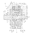
サイクロイド式の減速機Bは、図1~図3に示すように、入力軸30に設けられた偏心軸部30a、30bによって2枚の曲線板31を回転自在に支持し、それらの曲線板31の外周に形成された波形歯形31aを減速機Bのケーシング22bの内側に配設された外ピン32に噛合し、上記入力軸30の回転により曲線板31を偏心揺動運動させ、その曲線板31の自転を入力軸30と同軸上に配置された出力軸33から出力し、車輪ハブCを回転させている。
減速機Bのケーシング22bの内側に配設された外ピン32の数は、曲線板31の外周の波形歯形31aより多い。
外ピン32は、図2に示すように、減速機Bのケーシング22bの内径面に隙間を介して位置する外ピンハウジング50に支持されている。外ピンハウジング50は、減速機Bのケーシング22bに対してアウター側とインナー側に、フローティングボルト59によってフローティング支持されている。フローティングボルト59は、回転軸線Oを中心とする円周上に等間隔に配置され、外ピンハウジング側固定部59aとケーシング側固定部59bとを有し、外ピンハウジング側固定部59aとケーシング側固定部59bの間に、外ピンハウジング50の軸方向の外側面に固定される外ピンサイドプレート58の固定フランジ59cが設けられている。
外ピンハウジング50は、円筒部51と、円筒部51の軸方向両端部から径方向内側に延びる一対のリング部52とを備える。
入力軸30は、図1に示すように、その一端部がスプライン嵌合によりロータ24のモータ軸24aに接続されてモータ部Aにより回転駆動されるようになっており、その他端部に偏心軸部30a、30bが設けられている。
偏心軸部30a、30bは、図2に示すように、入力軸30の軸方向に一対設けられている。その一対の偏心軸部30a、30bは、円筒状外径面の中心が周方向に180°位相がずれるようにして設けられ、その一対の偏心軸部30a、30bのそれぞれの外径面に転がり軸受34が嵌合されている。
偏心軸部30a、30bには、油孔45a、45bが設けられ、この油孔45a、45bから入力軸30の内部通路45を通る潤滑油が飛散し、各部の転動面、摺動面を潤滑する。
偏心軸部30a、30bには、油孔45a、45bが設けられ、この油孔45a、45bから入力軸30の内部通路45を通る潤滑油が飛散し、各部の転動面、摺動面を潤滑する。
一対の偏心軸部30a、30bを設けた入力軸30には、一対の偏心軸部30a、30bを挟むように一対のカウンタウェイト35を、周方向に180°位相をずらして設けている。
曲線板31は、転がり軸受34によって入力軸30に回転自在に支持され、その外周に形成された波形歯形31aはトロコイド曲線歯形とされている。図3に示すように、曲線板31には、回転軸心を中心とする一つの円上に複数のピン孔36が等間隔に形成され、軸方向に並ぶ一対のピン孔36のそれぞれに内ピン37が余裕をもって挿入され、その内ピン37に回転自在に支持されたころ軸受37aの外周一部がピン孔36の内周一部に接触している。
減速機Bは、図2に示すように、偏心軸部30a、30bに回転自在に保持される公転部材としての2枚の曲線板31と、曲線板31の外周部の波形歯形31aに係合する複数の外ピン32と、曲線板31の自転運動を出力する出力軸33と、2枚の曲線板31の隙間に取り付けられてこれら曲線板31の端面に当接して曲線板31の傾きを防止するセンターカラー38とを備える。
出力軸33は、フランジ部33aと軸部33bとを有する。図1に示すように、フランジ部33aには、出力軸33の回転軸線Oを中心とする円周上に、内ピン37が等間隔に固定されている。軸部33bの外径面には、セレーション(またはスプライン)によりトルク伝達可能な状態で車輪ハブCが設けられている。複数の内ピン37を介しフランジ部33a、33aが連結された出力軸33のモータ部A側の端部には、オイルポンプ42のインナーロータ72に接続するポンプ駆動軸33cが設けられている。
外ピン32は、入力軸30の回転軸線Oの円周軌道上に等間隔に設けられる。そして、曲線板31が公転運動すると、外周の波形歯形31aと外ピン32とが係合して、曲線板31に自転運動を生じさせる。
図2に示すように、外ピンハウジング50の一対のリング部52の内周には、出力軸33が軸受90を介して回転自在に支持されている。また、出力軸33のフランジ部33aの内径面と入力軸30の外径面とは、軸受91を介して相対的に回転可能に支持されている。
曲線板31は、出力軸33の対向するフランジ部33a間に組み込まれている。また、出力軸33の対向するフランジ部33aには、組み込まれた曲線板31のピン孔36を貫通する内ピン37の両端が支持されている。
出力軸33の対向するフランジ部33aに支持された複数の内ピン37は、入力軸30の回転軸線Oを中心とする円周軌道上に等間隔に設けられ、曲線板31との摩擦抵抗を低減するために、2枚の曲線板31の各ピン孔36の内壁面に当接する位置に針状ころ軸受37aがそれぞれ設けられている。ピン孔36の内径寸法は、内ピン37の外径寸法(「針状ころ軸受37aを含む最大外径」を指す。以下同じ。)より所定分大きく設定されている。
車輪ハブCは、図1に示すように、出力軸33の軸部33bの外径面にセレーション(またはスプライン)によりトルク伝達可能な状態で嵌合連結された内輪部材81と、内輪部材81をケーシング22bに対して回転自在に保持する外輪部材82とを備える。内輪部材81と外輪部材82とは複列アンギュラ玉軸受を構成し、内輪部材81と外輪部材82の間に複列の転動体83を設置している。内輪部材81には、車輪取付けフランジ部84が一体に設けられている。
外ピン32は、ケーシング22bに直接保持されているわけではなく、図1及び図2に示すように、ケーシング22bの内径面にフローティング状態に支持された外ピンハウジング50に保持されている。
インホイールモータ駆動装置21においては、軽量化の観点からケーシング22は、アルミ合金やマグネシウム合金等の軽金属で形成し、高い強度が求められる外ピンハウジング50は、鋼で形成するのが望ましい。
外ピンハウジング50は、図5に示すように、円筒部51と、円筒部51の軸方向両端部から径方向内側に延びる一対のリング部52とを備える。
一対のリング部52は、径方向の外周側に位置する外側面部52aと、径方向の内周側に位置し、外側面部52aの外方に突出する厚肉の内側面部52bとからなる。
また、外ピンハウジング50の円筒部51の下部には、円筒部51を軸方向に分割するスリット53を設けている。
外ピンハウジング50の一対のリング部52には、厚み方向に貫通する複数の外ピン保持孔54を設けている。外ピン保持孔54は、図2に示すように、それぞれ入力軸30の回転軸線Oと平行な方向に延び外ピン32の両端を保持している。外ピン32の両端は、外ピン保持孔54に対して針状ころ軸受55を介して支持されている。針状ころ軸受55は、外輪55aと、この外輪55aの内周面と外ピン32の外周面とを転走面にした針状ころ55bとからなる。針状ころ軸受55の外輪55aは、外ピン保持孔54の内面に嵌合されている。
また、一対のリング部52の対応する外ピン保持孔54は、周方向の同位置に互いに対面するように設けられている。即ち、一対の外ピン保持孔54の中心軸線は一致し、外ピンハウジング50を減速機Bのケーシング22bに取り付けると、この外ピン保持孔54の中心軸線は、入力軸30の回転軸線Oと平行になる。
これにより、外ピン32を入力軸30の回転軸線Oと平行に保持することができる。なお、一対の外ピン保持孔54は同時加工で形成することができるので、対向する外ピン保持孔54の中心軸線を比較的簡単に一致させることができる。
図5に示すように、一対のリング部52の径方向の内周側に位置する厚肉の内側面部52bには、外ピン保持孔54に連続するように、溝形のザグリ部56が形成されている。
一対のリング部52の径方向の外周側に位置する外側面部52aには、図2に示すように、外ピン保持孔54に挿入した外ピン32の軸方向の抜け出しを防止する外ピンサイドプレート58がフローティングボルト59によって固定されている。
外ピンサイドプレート58は、図5に示すように、外ピンハウジング50の外側面部52aに設けられた固定孔52cとフローティングボルト59により締結されている。
外ピンハウジング50の円筒部51には、図2及び図5に示すように、外ピンハウジング50の円筒部51を貫通し、ケーシング22bの内径面と外ピンハウジング50内とを連通させる貫通孔57を設けている。
この貫通孔57は、図5に示すように、外ピン保持孔54の位相に合わせて、外ピンハウジング50の円筒部51の上半部に設けられている。
即ち、外ピンハウジング50の円筒部51の貫通孔57は、径方向に形成され、下部のスリット53部分を除いて周方向に複数個有し、おおむね中心線より上部に位置している。
貫通孔57の周方向の位相としては、外ピン保持孔54のある位相に設けるのがよい。外ピン保持孔54のある位相に設けると、貫通孔57の加工の深さが浅いため、加工時間を短縮できる。
この貫通孔57は、すべての外ピン保持孔54がある位相に開ける必要はなく、例えば、図6に示す実施形態のように、外ピン保持孔54のある位相の1個飛びに形成するようにしてもよい。
このように、外ピンハウジング50の円筒部51に貫通孔57を設けることにより、減速機Bの内部で回転に伴い飛散した潤滑油の内、各部の潤滑に寄与しなかった潤滑油が、貫通孔57から外ピンハウジング50の外部に飛散し、ケーシング22bの内径面に付着する。そして、潤滑油が重力によりケーシング22bの下部のオイルタンク41に流れ込むまでの間に、潤滑油の熱がケーシング22bに熱伝導し、この熱伝導により、潤滑油の温度が低下する。ケーシング22bは、走行風により冷却されているので、ケーシング22bとの接触により、潤滑油の油温の上昇が抑制され、結果としてモータ部Aの温度の上昇も抑制され、航続距離延長、定格出力の向上を図ることができる。
また、外ピンハウジング50の貫通孔57から外部に飛散した潤滑油は、ケーシング22bの内径面に付着し、冷却された潤滑油がしずく(油滴)となって、外ピンハウジング50の上部に位置する貫通孔57から滴下し、再び外ピンハウジング50の内部(減速機Bの内部)に戻ることで、減速機Bを冷却することもできる。
次に、図6及び図7に示す実施形態では、外ピンハウジング50の円筒部51の外径面には、外ピンハウジング50の外径面に付着した潤滑油が、外ピンハウジング50の外径面とケーシング22bの内径面との間を伝って下部のオイルタンク41に導き易くするために、円周溝61を設けている。この円周溝61は、図6に示す実施形態では、貫通孔57を挟むように貫通孔57の両側に2本設け、図7に示す実施形態では、周方向に設けられた貫通孔57を繋ぐように、中央に1本設けている。
また、サイクロイド式の減速機Bの潤滑は、オイルポンプ42から供給された潤滑油が、入力軸30の内部通路45を通り、偏心軸部30a、30bに設けた油孔45a、45bから飛散し飛沫となって、また、外ピンハウジング50の内部に溜まった潤滑油が、曲線板31の回転で掻き上げられ飛沫となって、各部の転動面、摺動面を潤滑する。
公転部材としての2枚の曲線板31の間には、曲線板31の傾きを防止するセンターカラー38を設けている。このため、このセンターカラー38にも、図8に示すように、径方向のスリット60を設け、入力軸30から偏心軸部30a、30bの油孔45a、45bを通って飛散した潤滑油が、センターカラー38のスリット60を通って飛散するようにすることが望ましい。このスリット60は、センターカラー38の両面に、周方向に位相をずらして交互に設けている。
センターカラー38のスリット60から飛散した潤滑油を効率よく外ピンハウジング50の外部に出すためには、外ピンハウジング50の貫通孔57は、ある程度の大きさが必要である。
ただし、外ピンハウジング50の貫通孔57が大きすぎると外ピンハウジング50の剛性・強度が低下する。低剛性による減速機Bの変形は、減速機Bからの異音発生の原因となる。そのため、貫通孔57の径φAは、センターカラー38の幅寸法aより大きくし、センターカラー38と曲線板31の総幅bより小さくし、また、スリット60から飛散した潤滑油が貫通孔57を通るように、貫通孔57の軸方向の位置は、センターカラー38の両幅面が貫通孔57内に位置するように配置する(図2参照)。
例えば、曲線板31が、2枚の場合には、貫通孔57の径φAは、下記式(1)を満足するようにする。
(センターカラー38の幅+曲線板31の幅×2)>φA>センターカラー38の幅・・・(1)
また、曲線板31の枚数が2枚以上、z枚(z≧2)の場合には、下記式(2)を満足するようにする。
(センターカラー38の幅×(z-1)+曲線板31の幅×z)>φA>(センターカラー38の幅×(z-1)+曲線板31の幅×(z-2))・・・(2)
外ピンハウジング50の貫通孔57は、丸穴であっても、長穴であってもよいし、多角形状の穴であってもよい。
インホイールモータ駆動装置21は、小型化の観点から、外ピンハウジング50の外径と、ケーシング22bの内径面との距離を小さくしているので、外ピンハウジング50の外部に飛散した潤滑油が、ケーシング22bの内径面と外ピンハウジング50の外径との間に溜まるおそれがある。潤滑油が、ケーシング22bの内径面と外ピンハウジング50の外径との間に溜まると、オイルタンク41から吸い上げられる潤滑油が不足し、各部の潤滑不良を引き起こす可能性がある。このため、飛散した潤滑油がケーシング22bの内径面を伝って底部に設けられた排出口47からオイルタンク41に流れ込みやすくするために、図9に示すように、円周溝62を設け、さらに、ケーシング22bの内径面の底部に、円周溝62と排出口47とを繋ぐ交差溝63を設けている。図9の実施形態では、円周溝62を2本設けているが、1本でもよい。
上記構成のインホイールモータ駆動装置21のモータ部Aは、例えば、ステータ23のコイルに交流電流を供給することによって生じる電磁力を受けて、永久磁石または磁性体によって構成されるロータ24が回転する。
これにより、ロータ24に接続されたモータ軸24aが回転すると、曲線板31はモータ軸24aの回転軸線Oを中心として公転運動する。このとき、外ピン32が、曲線板31の曲線形状の波形歯形と転がり接触するよう係合して、曲線板31をモータ軸24aの回転とは逆向きに自転運動させる。
曲線板31のピン孔36に挿通する内ピン37は、ピン孔36の内径よりも十分に細く、曲線板31の自転運動に伴ってピン孔36の内壁面と当接する。これにより、曲線板31の公転運動が内ピン37に伝わらず、曲線板31の自転運動のみが出力軸33を介して車輪ハブCに伝達される。
このとき、回転軸線Oと同軸に配置された出力軸33は、減速機Bの出力軸として曲線板31の自転を取り出し、モータ軸24aの回転が減速機Bによって減速されて出力軸33に伝達されるので、低トルク、高回転型のモータ部Aを採用した場合でも、駆動輪に必要なトルクを伝達することが可能となる。
このように、多段構成とすることなく大きな減速比を得ることができる減速機Bを採用することにより、コンパクトで高減速比のインホイールモータ駆動装置21を得ることができる。また、外ピン32を外ピンハウジング50に対して回転自在とし、内ピン37の曲線板31に当接する位置に針状ころ軸受37aを設けたことにより、摩擦抵抗が低減されるので、減速機Bの伝達効率が向上する。
前記の実施形態においては、減速機Bの曲線板31を180°位相を変えて2枚設けたが、この曲線板の枚数は任意に設定することができ、例えば、曲線板を3枚設ける場合は、120°位相を変えて設けるとよい。
また、前記の実施形態において、曲線板31を支持する転がり軸受34として円筒ころ軸受の例を示したが、これに限ることなく、例えば、すべり軸受、深溝玉軸受、円錐ころ軸受、針状ころ軸受、自動調心ころ軸受、アンギュラ玉軸受、4点接触玉軸受等、すべり軸受であるか転がり軸受であるかを問わず、転動体がころであるか玉であるかを問わず、さらには複列か単列かを問わず、あらゆる軸受を適用することができる。また、その他の場所に配置される軸受についても、同様に任意の形態の軸受を採用することができる。
また、前記の実施形態においては、モータ部Aに、ケーシング22aに固定されるステータ23と、ステータ23の内側に径方向の隙間を空けて対面する位置に配置されるロータ24とを備えるラジアルギャップモータを採用した例を示したが、これに限ることなく、任意の構成のモータを適用可能である。例えばステータとロータとが軸方向に開いた隙間を介して対向配置されるアキシアルギャップモータであってもよい。
また、前記の実施形態においては、オイルポンプ42は、減速機Bの回転を利用してインナーロータ72が回転する例を示したが、これに限ることなく、モータ部Aのロータ24の回転を利用してインナーロータが回転するオイルポンプ、あるいは別途設けた電動モータによりインナーロータが回転するオイルポンプであってもよい。
また、前記の実施形態においては、電気自動車用駆動装置として車輪ハブCが駆動輪を直接駆動するインホイールモータ駆動装置21の例を示したが、これに限ることなく、インホイールモータ駆動装置21を車体側のサスペンションメンバにて支持し、左右一対の駆動輪をそれぞれ等速ジョイント等のドライブシャフトで駆動する、いわゆるオンボード駆動装置としても適用可能である。
また、前記の実施形態においては、電気自動車用駆動装置が走行風によって冷却される、いわゆる空冷の例を示したが、電気自動車用駆動装置のケーシング内に水路を設け、冷却水を循環させラジエターにて外気と熱交換し冷却する、いわゆる水冷の電気自動車用駆動装置であってもよい。
さらに、この発明に係る電気自動車用駆動装置を搭載した電気自動車は、後輪を駆動輪としてもよく、また、前輪を駆動輪としてもよく、4輪駆動車であってもよい。なお、本明細書中で「電気自動車」とは、電力から駆動力を得る全ての自動車を含む概念であり、例えば、ハイブリッドカー等をも含むものとして理解すべきである。
11 :電気自動車
12 :シャーシ
12a :ホイールハウジング
12b :懸架装置
13 :前輪
14 :駆動輪
21 :インホイールモータ駆動装置
22 :ケーシング
22a :ケーシング
22b :ケーシング
22c :仕切壁
23 :ステータ
24 :ロータ
24a :モータ軸
25a :軸受
25b :軸受
30 :入力軸
30a :偏心軸部
30b :偏心軸部
31 :曲線板
31a :波形歯形
32 :外ピン
33 :出力軸
33a :フランジ部
33b :軸部
33c :ポンプ駆動軸
34 :転がり軸受
35 :カウンタウェイト
36 :ピン孔
37 :内ピン
37a :軸受
38 :センターカラー
41 :オイルタンク
42 :オイルポンプ
43 :給油通路
44 :内部通路
45 :内部通路
45a :油孔
45b :油孔
46 :吸込通路
47 :排出口
50 :外ピンハウジング
51 :円筒部
52 :リング部
52a :外側面部
52b :内側面部
52c :固定孔
53 :スリット
54 :外ピン保持孔
55 :軸受
55a :外輪
55b :針状ころ
56 :ザグリ部
57 :貫通孔
58 :外ピンサイドプレート
59 :フローティングボルト
59a :外ピンハウジング側固定部
59b :ケーシング側固定部
59c :固定フランジ
60 :スリット
61 :円周溝
62 :円周溝
63 :交差溝
72 :インナーロータ
72a :歯先部分
72b :歯溝部分
73 :アウターロータ
73a :歯先部分
73b :歯溝部分
74 :ポンプ室
75 :吸入口
76 :吐出口
77 :ポンプケース
81 :内輪部材
82 :外輪部材
83 :転動体
84 :車輪取付けフランジ部
90 :軸受
91 :軸受
A :モータ部
B :減速機
C :車輪ハブ
O :回転軸線
a :幅寸法
b :総幅
c1 :回転中心
c2 :回転中心
φA :径
Claims (8)
- 駆動力を発生させるモータ部と、モータ部の回転を減速して出力する減速機と、減速機からの出力を駆動輪に伝える車輪ハブとを備え、前記減速機が、前記モータ部によって回転駆動される入力軸と、入力軸に設けられた偏心軸部によって入力軸に回転自在に支持され、外周に波形歯形が形成された曲線板と、減速機のケーシングの内側に配設され、曲線板の外周の波形歯形に噛合する外ピンとを有し、外ピンを、減速機のケーシングの内径面に回り止めされた外ピンハウジングに支持し、外ピンハウジングは、減速機のケーシングの内径面に設けられた円筒部と、円筒部の両端から内向きに形成された一対のリング部とからなり、外ピンハウジングの一対のリング部に外ピン保持孔を円周方向に複数設け、その外ピン保持孔内に組み込んだ軸受により外ピンを回転自在に支持し、入力軸の回転により曲線板を偏心揺動運動させて、その曲線板の自転を前記入力軸と同軸上に配置された出力軸から出力するようにしたサイクロイド式の減速機とされた電気自動車用駆動装置において、前記外ピンハウジングの円筒部に、ケーシングの内径面と外ピンハウジング内とを連通させる貫通孔を設けたことを特徴とする電気自動車用駆動装置。
- 前記貫通孔が外ピンハウジングの円筒部の上半部に設けられている請求項1記載の電気自動車用駆動装置。
- 前記曲線板が軸方向にセンターカラーを挟んで複数枚設けられ、曲線板と曲線板との間のセンターカラーに、径方向のスリットを設けたことを特徴とする請求項1又は2に記載の電気自動車用駆動装置。
- 前記貫通孔の軸方向の幅が、センターカラーの軸方向の幅よりも大きく、かつ曲線板とセンターカラーの軸方向の総幅よりも小さく、センターカラーの両幅面が、貫通孔内に位置することを特徴とする請求項3記載の電気自動車用駆動装置。
- 前記外ピンハウジングの円筒部の外径面に、円周溝を設けたことを特徴とする請求項1~4のいずれかの項に記載の電気自動車用駆動装置。
- 減速機のケーシングの内径面に、円周溝を設けたことを特徴とする請求項1~4のいずれかの項に記載の電気自動車用駆動装置。
- 前記車輪ハブが駆動輪を直接駆動するインホイールモータ駆動装置であることを特徴とする請求項1~6のいずれかの項に記載の電気自動車用駆動装置。
- 前記車輪ハブに締結されたドライブシャフトを介して駆動輪を駆動するオンボード駆動装置であることを特徴とする請求項1~6のいずれかの項に記載の電気自動車用駆動装置。
Applications Claiming Priority (2)
| Application Number | Priority Date | Filing Date | Title |
|---|---|---|---|
| JP2014002101A JP2015129570A (ja) | 2014-01-09 | 2014-01-09 | 電気自動車用駆動装置 |
| JP2014-002101 | 2014-01-09 |
Publications (1)
| Publication Number | Publication Date |
|---|---|
| WO2015105097A1 true WO2015105097A1 (ja) | 2015-07-16 |
Family
ID=53523922
Family Applications (1)
| Application Number | Title | Priority Date | Filing Date |
|---|---|---|---|
| PCT/JP2015/050133 WO2015105097A1 (ja) | 2014-01-09 | 2015-01-06 | 電気自動車用駆動装置 |
Country Status (2)
| Country | Link |
|---|---|
| JP (1) | JP2015129570A (ja) |
| WO (1) | WO2015105097A1 (ja) |
Cited By (3)
| Publication number | Priority date | Publication date | Assignee | Title |
|---|---|---|---|---|
| CN105114544A (zh) * | 2015-09-21 | 2015-12-02 | 陈伟 | 双区式夹层箱体风冷动平衡内摆线减速箱 |
| CN105114543A (zh) * | 2015-09-21 | 2015-12-02 | 陈伟 | 双区式夹层箱体水冷动平衡内摆线减速箱 |
| WO2019011614A1 (en) * | 2017-07-14 | 2019-01-17 | Robert Bosch Gmbh | ELECTRIC VEHICLE AND ITS WHEEL ASSEMBLY |
Families Citing this family (3)
| Publication number | Priority date | Publication date | Assignee | Title |
|---|---|---|---|---|
| JP6508148B2 (ja) * | 2016-08-29 | 2019-05-08 | トヨタ自動車株式会社 | インホイールモータユニット |
| DE112020005868A5 (de) * | 2019-11-29 | 2022-09-15 | Magna powertrain gmbh & co kg | Gehäuse für eine elektrische Maschine sowie elektrische Maschine umfassend ein solches Gehäuse |
| DE102019132590B4 (de) * | 2019-12-02 | 2023-01-26 | Audi Ag | Antriebsvorrichtung für ein Fahrzeug |
Citations (3)
| Publication number | Priority date | Publication date | Assignee | Title |
|---|---|---|---|---|
| JP2010221964A (ja) * | 2009-03-25 | 2010-10-07 | Ntn Corp | インホイールモータ駆動装置 |
| JP2012202457A (ja) * | 2011-03-24 | 2012-10-22 | Ntn Corp | サイクロイド減速機及びインホイールモータ駆動装置 |
| JP2013148198A (ja) * | 2012-01-23 | 2013-08-01 | Ntn Corp | 車輪駆動装置 |
-
2014
- 2014-01-09 JP JP2014002101A patent/JP2015129570A/ja active Pending
-
2015
- 2015-01-06 WO PCT/JP2015/050133 patent/WO2015105097A1/ja active Application Filing
Patent Citations (3)
| Publication number | Priority date | Publication date | Assignee | Title |
|---|---|---|---|---|
| JP2010221964A (ja) * | 2009-03-25 | 2010-10-07 | Ntn Corp | インホイールモータ駆動装置 |
| JP2012202457A (ja) * | 2011-03-24 | 2012-10-22 | Ntn Corp | サイクロイド減速機及びインホイールモータ駆動装置 |
| JP2013148198A (ja) * | 2012-01-23 | 2013-08-01 | Ntn Corp | 車輪駆動装置 |
Cited By (4)
| Publication number | Priority date | Publication date | Assignee | Title |
|---|---|---|---|---|
| CN105114544A (zh) * | 2015-09-21 | 2015-12-02 | 陈伟 | 双区式夹层箱体风冷动平衡内摆线减速箱 |
| CN105114543A (zh) * | 2015-09-21 | 2015-12-02 | 陈伟 | 双区式夹层箱体水冷动平衡内摆线减速箱 |
| WO2019011614A1 (en) * | 2017-07-14 | 2019-01-17 | Robert Bosch Gmbh | ELECTRIC VEHICLE AND ITS WHEEL ASSEMBLY |
| US11524568B2 (en) | 2017-07-14 | 2022-12-13 | Robert Bosch Gmbh | Electric vehicle and the wheel assembly thereof |
Also Published As
| Publication number | Publication date |
|---|---|
| JP2015129570A (ja) | 2015-07-16 |
Similar Documents
| Publication | Publication Date | Title |
|---|---|---|
| US9077222B2 (en) | In-wheel motor drive assembly | |
| WO2015105097A1 (ja) | 電気自動車用駆動装置 | |
| JP5158861B2 (ja) | インホイールモータ駆動装置 | |
| JP5374215B2 (ja) | サイクロイド減速機、インホイールモータ駆動装置、および車両用モータ駆動装置 | |
| JP5778433B2 (ja) | インホイールモータ駆動装置 | |
| JP5079431B2 (ja) | インホイールモータ駆動装置 | |
| JP2016049916A (ja) | インホイールモータ駆動装置 | |
| JP5032382B2 (ja) | モータ駆動装置およびインホイールモータ駆動装置 | |
| JP5687839B2 (ja) | インホイールモータ駆動装置 | |
| JP2016111723A (ja) | 車輪駆動装置 | |
| JP2009262616A (ja) | モータ駆動装置およびインホイールモータ駆動装置 | |
| JP2012171420A (ja) | インホイールモータ駆動装置 | |
| JP2016063689A (ja) | インホイールモータ駆動装置 | |
| JP5176183B2 (ja) | インホイールモータ駆動装置 | |
| JP2015055343A (ja) | インホイールモータ駆動装置 | |
| JP2016142362A (ja) | インホイールモータ駆動装置 | |
| JP2016148411A (ja) | 車輪駆動装置 | |
| WO2015016058A1 (ja) | インホイールモータ駆動装置の潤滑装置 | |
| JP2016065616A (ja) | インホイールモータ駆動装置 | |
| JP2015175383A (ja) | インホイールモータ駆動装置 | |
| JP2015068418A (ja) | インホイールモータ駆動装置 | |
| JP6333579B2 (ja) | インホイールモータ駆動装置 | |
| JP2015183831A (ja) | インホイールモータ駆動装置 | |
| JP2016070298A (ja) | インホイールモータ駆動装置 | |
| JP2017024655A (ja) | インホイールモータ駆動装置 |
Legal Events
| Date | Code | Title | Description |
|---|---|---|---|
| 121 | Ep: the epo has been informed by wipo that ep was designated in this application |
Ref document number: 15734873 Country of ref document: EP Kind code of ref document: A1 |
|
| NENP | Non-entry into the national phase |
Ref country code: DE |
|
| 122 | Ep: pct application non-entry in european phase |
Ref document number: 15734873 Country of ref document: EP Kind code of ref document: A1 |