WO2015102108A1 - 強化ガラス板およびその製造方法 - Google Patents
強化ガラス板およびその製造方法 Download PDFInfo
- Publication number
- WO2015102108A1 WO2015102108A1 PCT/JP2015/050015 JP2015050015W WO2015102108A1 WO 2015102108 A1 WO2015102108 A1 WO 2015102108A1 JP 2015050015 W JP2015050015 W JP 2015050015W WO 2015102108 A1 WO2015102108 A1 WO 2015102108A1
- Authority
- WO
- WIPO (PCT)
- Prior art keywords
- stress layer
- compressive stress
- tempered glass
- glass plate
- main surface
- Prior art date
- Legal status (The legal status is an assumption and is not a legal conclusion. Google has not performed a legal analysis and makes no representation as to the accuracy of the status listed.)
- Ceased
Links
Images


Classifications
-
- C—CHEMISTRY; METALLURGY
- C03—GLASS; MINERAL OR SLAG WOOL
- C03C—CHEMICAL COMPOSITION OF GLASSES, GLAZES OR VITREOUS ENAMELS; SURFACE TREATMENT OF GLASS; SURFACE TREATMENT OF FIBRES OR FILAMENTS MADE FROM GLASS, MINERALS OR SLAGS; JOINING GLASS TO GLASS OR OTHER MATERIALS
- C03C3/00—Glass compositions
- C03C3/04—Glass compositions containing silica
- C03C3/076—Glass compositions containing silica with 40% to 90% silica, by weight
- C03C3/089—Glass compositions containing silica with 40% to 90% silica, by weight containing boron
- C03C3/091—Glass compositions containing silica with 40% to 90% silica, by weight containing boron containing aluminium
Definitions
- the present invention relates to a tempered glass plate and a manufacturing method thereof, and more specifically, to a tempered glass plate chemically strengthened by an ion exchange method and a manufacturing method thereof.
- a chemically strengthened tempered glass plate has been used for a touch panel display mounted on an electronic device such as a smartphone or a tablet PC.
- Such a tempered glass plate is generally produced by treating a glass substrate containing an alkali metal oxide as a composition with a tempering liquid to form a compressive stress layer on the surface. Since such a tempered glass plate has high strength, it is difficult to stably perform mechanical cutting.
- Patent Document 1 a technique of cutting (melting) a glass substrate used for a cover glass by etching has been developed (for example, Patent Document 1).
- the method for manufacturing a glass substrate disclosed in Patent Document 1 cuts the tempered glass by partially forming a resist film on both sides of the tempered glass to be cut and etching portions not protected by the resist film. it can.
- the tempered glass plate 31 generally chemically strengthened includes compressive stress layers 32A and 32B and an incompressible stress layer 33 in which the compressive stress layers 32A and 32B are not formed.
- a protrusion 35 is formed on the melted surface 34.
- the protrusion part 35 is easily chipped when subjected to an impact.
- the protrusion part 35 is missing, a crack will generate
- the present invention has been made in consideration of such circumstances, and it is an object of the present invention to provide a tempered glass sheet having a high end face impact resistance and easily manufactured, and a method for manufacturing the same.
- the tempered glass plate of the present invention is a tempered glass plate having a compressive stress layer on at least one of opposing main surfaces, and the end surface of the tempered glass plate has a compressive stress layer portion and a compressive stress layer on which the compressive stress layer is formed. And a non-compressive stress layer portion that is not formed, and further includes a protrusion when viewed in cross-section in the thickness direction, and the top of the protrusion is formed in the compressive stress layer portion.
- the tempered glass plate of the present invention it is possible to obtain a higher end face impact resistance than the conventional product. Specifically, since the protruding portion is formed in the compressive stress layer portion, the protruding portion is hardly chipped and cracks due to the chipping of the protruding portion are difficult to occur. Therefore, breakage of the tempered glass plate due to such cracks can be suppressed.
- the top portion of the protruding portion is located on the center side in the plate thickness direction from the main surface.
- the protruding portion is less likely to be chipped, and higher impact resistance can be obtained.
- the depth from the main surface of the compressive stress layer with respect to the thickness of the tempered glass sheet is preferably 1/100 to 1/10.
- the top portion of the protruding portion has a convex curved shape in a sectional view.
- the protruding portion is less likely to be chipped, and higher impact resistance can be obtained.
- a compressive stress layer having a tensile stress layer on the center side in the plate thickness direction from the compressive stress layer is 300 MPa or more, the depth from the main surface of the compressive stress layer is 5 to 100 ⁇ m,
- the tensile stress is preferably 10 MPa or more.
- the method for producing a tempered glass plate of the present invention is a method for producing a tempered glass plate by fusing a chemically strengthened mother glass plate, and a compressive stress layer is formed in the melted cross section at the time of fusing. Protruding portions are formed at the formed locations.
- the method for producing a tempered glass sheet of the present invention it is possible to easily produce a tempered glass sheet having a higher end face impact resistance than that of a conventional product without requiring a step of removing the protruding portion.
- the cutting planned portion of the chemically strengthened mother glass plate after etching the planned cutting portion of the chemically strengthened mother glass plate from the one main surface side to the compressive stress layer on the other main surface side, the cutting planned portion from the other main surface side. It is preferable to form the protrusion by etching.
- the protruding portion can be easily formed in the compressive stress layer portion. Moreover, the self-breakage of the mother glass plate at the time of fusing can be suppressed.
- the mother glass plate has a tensile stress layer on the center side in the thickness direction from the compressive stress layer, the compressive stress of the compressive stress layer is 300 MPa or more, and the main surface of the compressive stress layer Is preferably 5 to 100 ⁇ m, and the tensile stress of the tensile stress layer is preferably 10 MPa or more.
- FIGS. 2A to 2D are diagrams showing an example of a manufacturing process of a tempered glass sheet according to an embodiment of the present invention. It is sectional drawing which shows an example of the end surface shape of the tempered glass board which concerns on embodiment of this invention. It is a figure which shows an example of the test method which evaluates the impact resistance of the tempered glass board of this invention. It is sectional drawing which shows an example of the end surface shape of the conventional tempered glass board fuse
- the tempered glass plate 1 of the present invention is a chemically tempered glass having a main surface 2A and a main surface 2B facing each other.
- a compressive stress layer 3A is formed near the main surface 2A, and a compressive stress layer 3B is formed near the main surface 2B.
- region in which the compressive-stress layer is not formed in the tempered glass board 1 is called the non-compressive-stress layer 4.
- the end surface 5 of the tempered glass plate 1 is composed of compressive stress layer portions 6A and 6B on which a compressive stress layer is formed, and an uncompressed stress layer portion 7 on which no compressive stress layer is formed.
- the compressive stress layer 6A corresponds to the end of the compressive stress layer 3A
- the compressive stress layer 6B corresponds to the end of the compressive stress layer 3B.
- a protruding portion 8 protruding partially is formed.
- the top part 9 of the protrusion part 8 is located in the compressive-stress layer part 6B.
- the composition of the tempered glass plate 1 may be arbitrary.
- the glass composition may be 50% by mass of SiO 2 50-80%, Al 2 O 3 5-25%, B 2 O 3 0-15%, Na It is preferable to contain 2 O 1 to 20% and K 2 O 0 to 10%. If the glass composition range is regulated as described above, it becomes easy to achieve both ion exchange performance and devitrification resistance at a high level.
- the depth from the main surface of each of the compressive stress layers 3A and 3B with respect to the thickness of the tempered glass plate 1 is preferably 1/100 to 1/10.
- the thickness of the tempered glass plate 1 is, for example, 0.3 to 1.3 mm, and preferably 0.4 to 0.7 mm.
- the depth from the main surface of each of the compressive stress layers 3A and 3B is, for example, 5 to 100 ⁇ m, preferably 10 to 80 ⁇ m, more preferably 15 to 50 ⁇ m.
- the compressive stress of each of the compressive stress layers 3A and 3B is 300 MPa or more, preferably 500 to 1200 MPa, more preferably 600 to 1000 MPa, and still more preferably 700 to 1000 MPa.
- a tensile stress layer (not shown) is formed on the center side in the plate thickness direction of each of the compressive stress layers 3A and 3B.
- the tensile stress of the tensile stress layer is 10 MPa or more, preferably 10 to 200 MPa, more preferably 15 MPa to 150 MPa, and further preferably 25 to 90 MPa.
- the tempered glass plate 1 of the present invention since the top portion 9 is formed on the compressive stress layer portion 6B having high strength, the protruding portion 8 is hardly chipped. That is, the tempered glass plate 1 has high impact resistance at the end face.
- the top part 9 of the protrusion part 8 is located in the plate
- the tempered glass plate 1 of the present invention can be manufactured, for example, by fusing a mother glass plate (hereinafter, also simply referred to as “mother glass”) G as shown in FIGS. 2A to 2D.
- the mother glass G is a glass plate having the same composition as the tempered glass plate 1 and chemically strengthened in advance.
- the mother glass G includes a main surface 2A and a main surface 2B facing each other, and a compressive stress layer 3A is formed in the vicinity of the main surface 2A, and a compressive stress layer 3B is formed in the vicinity of the main surface 2B.
- a tensile stress layer is formed between the compressive stress layer 3A and the compressive stress layer 3B of the base glass G.
- the tensile stress of the tensile stress layer of the mother glass G is preferably 200 MPa or less, more preferably 10 to 200 MPa, still more preferably 15 MPa to 150 MPa, and most preferably 25 to 90 MPa. If the tensile stress of the tensile stress layer of the mother glass G is too large, the mother glass G is likely to be damaged due to the tensile stress in the manufacturing process of the tempered glass sheet 1 described later (the dividing process of the mother glass G). On the other hand, if the tensile stress of the tensile stress layer of the mother glass G is too small, the compressive stress layers 3A and 3B of the mother glass G need to be reduced in magnitude, and the strength of the resulting tempered glass plate 1 is high. It will decline.
- a resist film 10A is formed on the main surfaces 2A and 2B except for the planned cutting region 11A set on the main surface 2A of the mother glass G and the planned cutting region 11B set on the main surface 2B. 10B is formed.
- the scheduled cutting regions 11A and 11B are, for example, strip-shaped regions along the planned cutting line set in the mother glass G.
- any known material may be used as long as it is a material that is not affected by the etching solution 12 described later.
- known resist materials including organic, inorganic, and metal can be used.
- a method for forming the resist films 10A and 10B for example, a known method such as a photoresist method, a screen method, or a mechanical mask method may be used.
- the etching solution 12 is caused to flow from the main surface 2A side to the mother glass G, and the mother glass G is etched in the planned cutting region 11A. At this time, etching is performed until the molten cross section reaches the compressive stress layer 3B from the main surface 2A. At this time, the etching is performed to such an extent that the molten section does not reach the main surface 2B, that is, does not penetrate the mother glass G.
- Any known liquid may be used as the etching liquid 12 as long as it is a liquid capable of etching the mother glass G.
- hydrofluoric acid and a solution containing hydrofluoric acid can be used for the etchant 12.
- the etching solution 12 is caused to flow down from the main surface 2B side to the mother glass G, and the mother glass G is etched in the planned cutting region 11B.
- the mother glass G is divided.
- etching is preferably performed after the front and back posture of the mother glass G is reversed from the state of FIG.
- the width of the planned cutting area 11B is preferably smaller than the width of the planned cutting area 11A.
- the width of the planned cutting region 11B is set in this manner, the mother glass G is hardly etched from the main surface 2B side, and the top portion 9 of the protruding portion 8 can be more reliably formed on the compressive stress layer portion 6B. Become.
- the tempered glass 1 is obtained by removing the resist films 10A and 10B.
- the protruding portion 8 can be easily formed on the compressive stress layer portion 6B. Moreover, the protrusion part 8 can be formed so that the top part 9 of the protrusion part 8 may be located in the plate
- the damage of the mother glass G at the time of fusing can be suppressed.
- the tensile stress of the tensile stress layer in the mother glass G is relatively large, if the compressive stress layers 3A and 3B on both main surfaces are etched simultaneously as in the conventional method, the compressive stress and tensile stress in the mother glass G There was a risk of self-destruction.
- the above self-destruction can be suppressed.
- the step of FIG. 2C may be omitted, and the mother glass G may be fused by performing etching up to the main surface 2B in FIG. 2B.
- top part 9 of the protrusion part 8 has a sharp shape
- the top part of the protrusion part 8 is formed in the compressive stress layer part 6 ⁇ / b> B, as shown in FIG. 3. It may be rounded. That is, the top of the protrusion 8 may be a curved top 15 by a process such as mechanical polishing or etching.
- Tables 1 and 2 show examples and comparative examples of the present invention.
- test no. Nos. 1 and 2 are examples of the present invention.
- 3 shows a comparative example.
- the mother glasses ⁇ , ⁇ , and ⁇ serving as test samples were prepared.
- the mother glasses ⁇ , ⁇ , and ⁇ are in mass% as a glass composition, SiO 2 62.0%, Al 2 O 3 19.7%, B 2 O 3 3.6%, Na 2 O 13.2%, MgO
- a glass plate containing 1.5% is chemically strengthened by an ion exchange method under different temperature and time conditions.
- the mother glasses ⁇ , ⁇ , and ⁇ have different characteristics such as compressive stress.
- the main glass ⁇ , ⁇ , and ⁇ are respectively cut from the one side shown in FIGS. 2A to 2D, and the main glass is immersed in an etching solution in place of the steps shown in FIGS.
- FIG. 4 is a diagram showing a method for evaluating the impact resistance of the end face of the sample S.
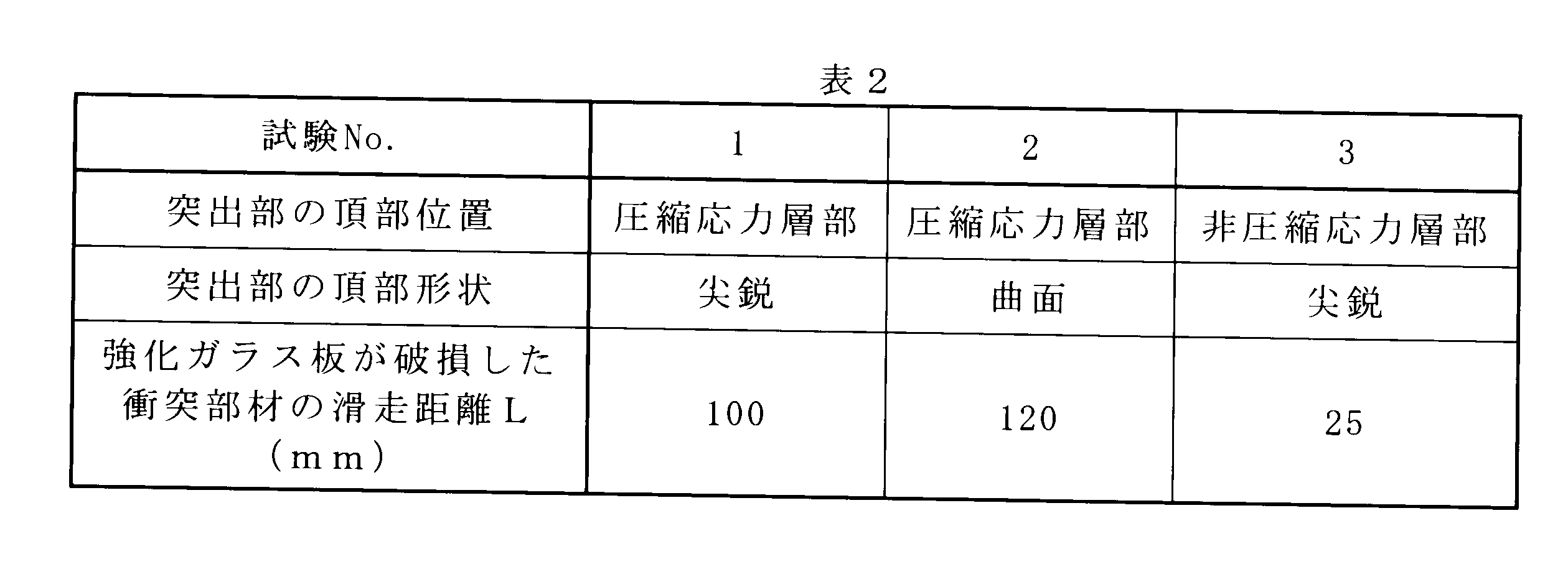
- the sample S of each test differs in the position of the top part of a protrusion part as described in Table 2. Specifically, Test No. Samples 1 and 2 were melted by etching from one side as shown in FIGS. 2A to 2D so that the protruding portion was positioned in the compressive stress layer. In addition, Test No. In the sample No. 3, the mother glass ⁇ was etched from both main surfaces at the same time and melted so that the protruding portion was located in the incompressible stress layer portion.
- the sample S has a length of 130 mm, a width of 65 mm, and a thickness of 0.7 mm. Thereafter, test no. For sample 2 of No. 2, the top of the protrusion was polished with a polishing tape, and the shape of the top of the protrusion was curved. In addition, Test No. For Samples 1 and 3, the tops of the protrusions were not processed as they were after cutting, but were sharpened.
- the impact resistance of the end face was evaluated for each sample obtained as described above. Details of the evaluation method will be described below. First, the sample S was held on the jig 20 so that the molten cross section was exposed. Next, the jig 20 was fixed below the inclined surface of the inclined table 21 having an inclined surface with an inclination angle of 32 °. Then, the collision member 22 was slid down from above the inclined surface of the inclined table 21 to be collided with the molten surface of the sample S.
- the collision member 22 is, for example, a 190 g stainless steel block.
- the above collision test was repeated by changing the sliding distance L of the collision member 22. Specifically, the sliding distance L was gradually increased from 5 mm to 5 mm until the sample S was damaged, and the sliding distance L at which the sample S was damaged was measured.
- the sliding distance L at which the sample S is damaged is preferably 30 mm or more, more preferably 50 mm or more. If the sliding distance L at which the sample S is damaged is 50 mm or more, it can be said that the sample has sufficient impact resistance as a cover glass for a smartphone, a tablet-type terminal or the like.
- the tempered glass plate and the method for producing the same of the present invention are useful as a glass substrate used for a touch panel display and the like, and a method for producing the same.
Landscapes
- Chemical & Material Sciences (AREA)
- Life Sciences & Earth Sciences (AREA)
- Engineering & Computer Science (AREA)
- Chemical Kinetics & Catalysis (AREA)
- General Chemical & Material Sciences (AREA)
- Geochemistry & Mineralogy (AREA)
- Materials Engineering (AREA)
- Organic Chemistry (AREA)
- Surface Treatment Of Glass (AREA)
- Re-Forming, After-Treatment, Cutting And Transporting Of Glass Products (AREA)
Abstract
本発明は、端面の耐衝撃性が高く且つ容易に製造可能な強化ガラス板およびその製造方法を提供することを目的とする。本発明の強化ガラス板は、対向する主面の少なくとも一方に圧縮応力層を有する強化ガラス板であって、該強化ガラス板の端面は、圧縮応力層が形成された圧縮応力層部と、圧縮応力層が形成されていない非圧縮応力層部とを有し、厚さ方向に断面視した場合に突出部をさらに備え、突出部の頂部が圧縮応力層部に形成されている。
Description
本発明は、強化ガラス板およびその製造方法に関し、より具体的には、イオン交換法によって化学強化された強化ガラス板およびその製造方法に関する。
従来、スマートフォンやタブレットPCなどの電子機器に搭載されるタッチパネルディスプレイには、化学強化された強化ガラス板が用いられている。
このような強化ガラス板は、一般的に、アルカリ金属酸化物を組成として含むガラス基板を強化液で処理し、表面に圧縮応力層を形成することによって製造される。このような強化ガラス板は高い強度を有するが故に機械的な切断を安定して行うことが困難である。
このような問題を解決すべく、カバーガラスに用いられるガラス基板をエッチングにより切断(溶断)する技術が開発されている(例えば、特許文献1)。特許文献1に開示されるガラス基材の製造方法は、切断対象となる強化ガラスの両面にレジスト膜を部分的に形成し、レジスト膜で保護されていない部位をエッチングすることによって強化ガラスを切断できる。
図5に示すように、一般的に化学強化された強化ガラス板31は、圧縮応力層32A、32Bと、圧縮応力層32A、32Bが形成されていない非圧縮応力層33とを有する。このような強化ガラス板31を特許文献1のようにエッチングにより溶断すると溶断面34に突出部35が形成される。突出部35が強化ガラス板31の非圧縮応力層33に形成されている場合、衝撃を受けた際に該突出部35が欠け易くなる。そして、突出部35が欠けると、欠けた箇所からクラックが発生および進展し、強化ガラス板31が破損するおそれがある。そのため、従来の技術においては、突出部35をさらにエッチングする等して除去する工程が必須であった。
本発明は、このような事情を考慮して成されたものであり、端面の耐衝撃性が高く且つ容易に製造可能な強化ガラス板およびその製造方法を提供することを課題とする。
本発明の強化ガラス板は、対向する主面の少なくとも一方に圧縮応力層を有する強化ガラス板であって、強化ガラス板の端面は、圧縮応力層が形成された圧縮応力層部と圧縮応力層が形成されていない非圧縮応力層部とを有し、厚さ方向に断面視した場合に突出部をさらに備え、突出部の頂部が圧縮応力層部に形成されていることを特徴とする。
本発明の強化ガラス板によれば、従来品に比べ高い端面の耐衝撃性を得られる。具体的には、突出部が圧縮応力層部に形成されているため、該突出部が欠け難く、突出部の欠けに起因するクラックが発生し難い。したがって、このようなクラックによる強化ガラス板の破損を抑制することができる。
本発明の強化ガラス板は、突出部の頂部は主面より板厚方向中央側に位置することが好ましい。
このような構成によれば、突出部が、より欠け難くなり、より高い耐衝撃性を得られる。
本発明の強化ガラス板は、強化ガラス板の板厚に対する圧縮応力層の主面からの深さが1/100~1/10であることが好ましい。
このような構成によれば、突出部を圧縮応力層部に形成し易い。
本発明の強化ガラス板は、突出部の頂部は断面視凸曲面状を成すことが好ましい。
このような構成によれば、突出部が、より欠け難くなり、より高い耐衝撃性を得られる。
圧縮応力層より板厚方向中央側に引張応力層を有し、圧縮応力層の圧縮応力が300MPa以上であり、圧縮応力層の主面からの深さが5~100μmであり、引張応力層の引張応力が10MPa以上であることが好ましい。
このような構成によれば、タッチパネルディスプレイ等の用途のガラス基板として好適な強度を得ることができる。
本発明の強化ガラス板の製造方法は、化学強化された母ガラス板を溶断して強化ガラス板を製造する強化ガラス板の製造方法であって、溶断時に、溶断面のうち圧縮応力層が形成された箇所に突出部を形成することを特徴とする。
本発明の強化ガラス板の製造方法によれば、従来品に比べ高い端面の耐衝撃性を有する強化ガラス板を、突出部を除去する工程を必要とすることなく容易に製造することができる。
本発明の強化ガラス板の製造方法では、化学強化された母ガラス板の切断予定箇所を一方主面側から他方主面側の圧縮応力層までエッチングした後、切断予定箇所を他方主面側からエッチングすることにより突出部を形成することが好ましい。
このような構成によれば、突出部を圧縮応力層部に容易に形成できる。また、溶断時における母ガラス板の自己破壊を抑制できる。
本発明の強化ガラス板の製造方法において、母ガラス板は圧縮応力層より板厚方向中央側に引張応力層を有し、圧縮応力層の圧縮応力が300MPa以上であり、圧縮応力層の主面からの深さが5~100μmであり、引張応力層の引張応力が10MPa以上であることが好ましい。
このような構成によれば、タッチパネルディスプレイ等の用途のガラス基板として好適な強度を得ることができる。また、引張応力が大きく自己破壊し易い母ガラス板であっても、破損することなく溶断できる。
本発明によれば、上述のように、端面の耐衝撃性が高く且つ容易に製造可能な強化ガラス板およびその製造方法を提供することができる。
以下、本発明の実施形態の強化ガラス板1およびその製造方法について説明する。
図1に示すように、本発明の強化ガラス板1は、互いに対向する主面2A、主面2Bを備えた化学強化ガラスである。主面2A近傍には圧縮応力層3Aが、主面2B近傍には圧縮応力層3Bが形成されている。なお、強化ガラス板1において圧縮応力層が形成されていない領域を非圧縮応力層4と称する。強化ガラス板1の端面5は、圧縮応力層が形成された圧縮応力層部6A、6B、および圧縮応力層が形成されていない非圧縮応力層部7から成る。なお、圧縮応力層部6Aは圧縮応力層3Aの端部に相当し、圧縮応力層部6Bは圧縮応力層3Bの端部に相当する。強化ガラス板1の端面5には、部分的に突出した突出部8が形成されている。そして、突出部8の頂部9は、圧縮応力層部6Bに位置する。
強化ガラス板1の組成は任意のもので良いが、例えば、ガラス組成として、質量%で、SiO2 50~80%、Al2O3 5~25%、B2O3 0~15%、Na2O 1~20%、K2O 0~10%を含有することが好ましい。上記のようにガラス組成範囲を規制すれば、イオン交換性能と耐失透性を高いレベルで両立し易くなる。
また、強化ガラス板1の板厚に対する圧縮応力層3A、3B各々の主面からの深さが1/100~1/10であることが好ましい。強化ガラス板1の板厚は、例えば0.3~1.3mmであり、好ましくは0.4~0.7mmである。圧縮応力層3A、3B各々の主面からの深さは例えば5~100μmであり、好ましくは10~80μm、より好ましくは15~50μmである。圧縮応力層3A、3B各々の圧縮応力は、300MPa以上、好ましくは、500~1200MPa、より好ましくは600~1000MPa、さらに好ましくは700~1000MPaである。なお、圧縮応力層3A、3B各々の板厚方向中央側には引張応力層(図示せず)が形成されている。引張応力層の引張応力は、10MPa以上、好ましくは10~200MPa、より好ましくは15MPa~150MPa、さらに好ましくは25~90MPaである。
上記本発明の強化ガラス板1によれば、頂部9が強度の高い圧縮応力層部6Bに形成されているため突出部8が欠け難い。すなわち、強化ガラス板1は端面において高い耐衝撃性を有する。
なお、突出部8の頂部9は、主面2Bより強化ガラス板1の板厚方向中央側に位置することが好ましい。このような構成によれば、頂部9が主面2Bの面上に位置する場合より突出部8を欠けにくくすることができる。
本発明の強化ガラス板1は、例えば、図2A~Dに示すように母ガラス板(以下、単に「母ガラス」とも称する)Gをエッチングにより溶断して製造することができる。母ガラスGは、強化ガラス板1と同様の組成を有し、予め化学強化されたガラス板である。母ガラスGは、互いに対向する主面2A、主面2Bを備え、主面2A近傍には圧縮応力層3Aが、主面2B近傍には圧縮応力層3Bが形成されている。母ガラスGの圧縮応力層3Aと圧縮応力層3Bとの間には引張応力層が形成されている。母ガラスGの引張応力層の引張応力は、200MPa以下が好ましく、より好ましくは10~200MPa、さらに好ましくは15MPa~150MPa、もっとも好ましくは25~90MPaである。母ガラスGの引張応力層の引張応力が大きすぎると、後述する強化ガラス板1の製造過程(母ガラスGの分断工程)において、当該引張応力に起因して母ガラスGが破損し易くなる。一方、母ガラスGの引張応力層の引張応力を小さくし過ぎると、母ガラスGの圧縮応力層3A、3Bの圧縮応力の大きさを小さくする必要があり、得られる強化ガラス板1の強度が低下してしまう。
先ず、図2Aに示すように、母ガラスGの主面2Aに設定された切断予定領域11Aおよび主面2Bに設定された切断予定領域11Bを除く主面2A、2Bの領域にレジスト膜10A、10Bを形成する。切断予定領域11A、11Bは、例えば、母ガラスGに設定される切断予定線に沿った帯状の領域である。レジスト膜10A、10Bの材料は後述のエッチング液12に侵されない材料であれば任意の周知の材料を用いて良い。例えば、レジスト膜10A、10Bの材料としては周知の有機、無機、金属を含むレジスト材を用いることができる。レジスト膜10A、10Bの成膜方法は、例えば、フォトレジスト法、スクリーン法、メカマスク法等の周知の方法を用いて良い。
次に、図2Bに示すように、主面2A側からエッチング液12を母ガラスGに流下させ、切断予定領域11Aにおいて母ガラスGをエッチングする。この際、溶断面が主面2Aから圧縮応力層3Bに到達するまでエッチングを行う。この時点では、溶断面が主面2Bまで到達しない程度に、すなわち、母ガラスGを貫通しない程度にエッチングする。なお、エッチング液12は、母ガラスGをエッチング可能な液体であれば任意の周知の液体を用いて良い。例えば、エッチング液12には、フッ酸およびフッ酸を含む溶液等を用いることができる。
次に、図2Cに示すように、主面2B側からエッチング液12を母ガラスGに流下させ、切断予定領域11Bにおいて母ガラスGをエッチングする。この処理によって、母ガラスGが分断される。エッチング液12の供給口が母ガラスGの上方にのみ配置されている場合、母ガラスGの表裏姿勢を図2Bの状態から反転させた後にエッチングを行うと良い。なお、切断予定領域11Bの幅は切断予定領域11Aの幅より小さいことが好ましい。このように切断予定領域11Bの幅を設定すれば、母ガラスGが主面2B側から過剰にエッチングされ難くなり、突出部8の頂部9を、より確実に圧縮応力層部6Bに形成し易くなる。
次に、図2Dに示すようにレジスト膜10A、10Bを除去することによって、強化ガラス1を得る。
上記のような強化ガラス板1の製造方法によれば、突出部8を圧縮応力層部6Bに容易に形成できる。また、突出部8の頂部9が主面2Bよりも板厚方向中央側に位置するよう、突出部8を形成できる。
また、上記方法によれば、溶断時における母ガラスGの破損を抑制できる。例えば、母ガラスG内部の引張応力層の引張応力が比較的大きい場合、従来の方法のように両主面の圧縮応力層3A、3Bを同時にエッチングすると、母ガラスGにおける圧縮応力と引張応力とのバランスが急激に崩れてしまい、自己破壊を引き起こすおそれがあった。その点、上記方法によれば、応力のバランスが緩やかに変化するため上記のような自己破壊を抑制できる。
なお、より早く溶断を行いたい場合には、図2Cの工程を省略し、図2Bにおいて主面2Bまでエッチングを進めて母ガラスGを溶断しても構わない。
また、図1においては突出部8の頂部9が尖鋭な形状である場合を一例として説明したが、突出部8の頂部は圧縮応力層部6Bに形成されていれば、図3に示すように丸みを帯びた形状であっても良い。すなわち、突出部8の頂部を機械的な研磨加工やエッチング等の処理により、曲面形状の頂部15としても良い。
以下、実施例に基づいて、本発明を詳細に説明する。表1、2は本発明の実施例および比較例を示している。なお、表2において、試験No.1、2は本発明の実施例、No.3は比較例を示している。

以下のようにして、各試験を行った。まず、試験の試料となる母ガラスα、β、γを複数用意した。母ガラスα、β、γは、ガラス組成として質量%で、SiO2 62.0%、Al2O3 19.7%、B2O3 3.6%、Na2O 13.2%、MgO 1.5%を含有するガラス板を夫々異なる温度および時間条件でイオン交換法により化学強化したものである。母ガラスα、β、γは、表1に示すように夫々圧縮応力等の特性が異なる。これら母ガラスα、β、γを各々、上述の図2A~Dに示した片面からエッチングする切断方法、および図2B~Cに示す工程に代えて母ガラスをエッチング液に浸漬させて両主面から同時にエッチングする方法で切断した。表1では、各母ガラスα、β、γを切断した結果、切断中に破損したものにはBを、破損することなく切断できたものにはAを付して示す。表1に示す通り、引張応力が比較的大きい母ガラスγは、両面を同時にエッチングする切断方法では切断中に自己破壊によって破損した。一方、図2に示した本発明の切断方法によれば、母ガラスγを破損することなく切断できた。
次いで、母ガラスβを切断して得た試料Sの端面の耐衝撃性を評価した。図4は試料Sの端面の耐衝撃性の評価方法を示した図である。なお、各試験の試料Sは、表2に記載の通り、突出部の頂部の位置が各々異なる。具体的には、試験No.1、2の試料Sは上述の図2A~Dに示した片面からのエッチングにより突出部が圧縮応力層部に位置するよう溶断した。また、試験No.3の試料は、母ガラスβを両主面から同時にエッチングして、突出部が非圧縮応力層部に位置するよう溶断した。試料Sの寸法は、何れも長さ130mm、幅65mm、厚さ0.7mmである。その後、試験No.2の試料Sについては、突出部の頂部を研磨テープにより研磨加工して突出部の頂部の形状を曲面状とした。なお、試験No.1、3の試料Sについては、突出部の頂部は溶断後のまま加工せず、尖鋭な形状とした。
上記のようにして得た各試料について端面の耐衝撃性を評価した。以下、評価方法の詳細について説明する。先ず、治具20に試料Sを、溶断面が露出するよう保持させた。次いで、治具20を傾斜角32°の斜面を有する傾斜台21の斜面下方に固定した。そして、傾斜台21の斜面上方から衝突部材22を滑走降下させて試料Sの溶断面に衝突させた。衝突部材22は、例えば、190gのステンレス製ブロックである。上記の衝突試験を、衝突部材22の滑走距離Lを変更して繰り返し行った。具体的には、試料Sが破損するまで滑走距離Lを5mmから5mmずつ徐々に長くし、試料Sが破損した滑走距離Lを測定した。
滑走距離Lが長いほど試料Sに与えられる衝撃が大きくなるため、破損するまでの滑走距離Lが長いほど試料Sの耐衝撃性に優れると言える。試料Sが破損する滑走距離Lは、30mm以上であることが好ましく、より好ましくは50mm以上である。試料Sが破損する滑走距離Lが50mm以上であればスマートフォンやタブレット型端末等のカバーガラスとして十分な耐衝撃性を有すると言える。
表2に示すように、試験No.3の試料Sは突出部の頂部が非圧縮応力層部に形成されていたため、破損時の滑走距離が30mm未満と短く、他の試験の試料に比べ端面の耐衝撃性に劣っていた。
本発明を特定の態様を参照して詳細に説明したが、本発明の精神と範囲を離れることなく様々な変更および修正が可能であることは、当業者にとって明らかである。
なお、本出願は、2014年1月6日付で出願された日本国特許出願(特願2014-000197)に基づいており、その全体が引用により援用される。また、ここに引用されるすべての参照は全体として取り込まれる。
なお、本出願は、2014年1月6日付で出願された日本国特許出願(特願2014-000197)に基づいており、その全体が引用により援用される。また、ここに引用されるすべての参照は全体として取り込まれる。
本発明の強化ガラス板およびその製造方法は、タッチパネルディスプレイ等に用いられるガラス基板およびその製造方法等として有用である。
1、12、31 強化ガラス板
2A、2B 主面
3A、3B、32A、32B 圧縮応力層
4、33 非圧縮応力層
5 端面
6A、6B 圧縮応力層部
7 非圧縮応力層部
8 突出部
9、15 頂部
10A、10B レジスト膜
11A、11B 切断予定領域
12 エッチング液
20 治具
21 傾斜台
22 衝突部材
34、35 溶断面
G 母ガラス
L 滑走距離
S 試料
2A、2B 主面
3A、3B、32A、32B 圧縮応力層
4、33 非圧縮応力層
5 端面
6A、6B 圧縮応力層部
7 非圧縮応力層部
8 突出部
9、15 頂部
10A、10B レジスト膜
11A、11B 切断予定領域
12 エッチング液
20 治具
21 傾斜台
22 衝突部材
34、35 溶断面
G 母ガラス
L 滑走距離
S 試料
Claims (8)
- 対向する主面の少なくとも一方に圧縮応力層を有する強化ガラス板であって、
前記強化ガラス板の端面は、
前記圧縮応力層が形成された圧縮応力層部と
前記圧縮応力層が形成されていない非圧縮応力層部とを有し、
厚さ方向に断面視した場合に突出部をさらに備え、
前記突出部の頂部が前記圧縮応力層部に形成されている、強化ガラス板。 - 前記突出部の頂部は前記主面より板厚方向中央側に位置する、請求項1に記載の強化ガラス板。
- 板厚に対する前記圧縮応力層の主面からの深さが1/100~1/10である、請求項1または2に記載の強化ガラス板。
- 前記突出部の頂部は断面視凸曲面状を成す、請求項1から3の何れか一項に記載の強化ガラス板。
- 前記圧縮応力層より板厚方向中央側に引張応力層を有し、
前記圧縮応力層の圧縮応力が300MPa以上であり、
前記圧縮応力層の深さが5~100μmであり、
前記引張応力層の引張応力が10MPa以上である、請求項1から4の何れか一項に記載の強化ガラス板。 - 化学強化され圧縮応力層を有する母ガラス板を溶断して強化ガラス板を製造する強化ガラス板の製造方法であって、
前記溶断時に、溶断面のうち前記圧縮応力層が形成された箇所に突出部を形成する、強化ガラス板の製造方法。 - 前記母ガラス板は表裏両主面を化学強化されており、
前記母ガラス板の切断予定箇所を一方主面側から他方主面側の圧縮応力層までエッチングした後、前記切断予定箇所を他方主面側からエッチングすることにより前記突出部を形成する、請求項6に記載の強化ガラス板の製造方法。 - 前記母ガラス板は前記圧縮応力層より板厚方向中央側に引張応力層を有し、
前記圧縮応力層の圧縮応力が300MPa以上であり、
前記圧縮応力層の深さが5~100μmであり、
前記引張応力層の引張応力が10MPa以上である、請求項6または7に記載の強化ガラス板の製造方法。
Priority Applications (1)
| Application Number | Priority Date | Filing Date | Title |
|---|---|---|---|
| JP2015555890A JPWO2015102108A1 (ja) | 2014-01-06 | 2015-01-05 | 強化ガラス板およびその製造方法 |
Applications Claiming Priority (2)
| Application Number | Priority Date | Filing Date | Title |
|---|---|---|---|
| JP2014000197 | 2014-01-06 | ||
| JP2014-000197 | 2014-01-06 |
Publications (1)
| Publication Number | Publication Date |
|---|---|
| WO2015102108A1 true WO2015102108A1 (ja) | 2015-07-09 |
Family
ID=53493447
Family Applications (1)
| Application Number | Title | Priority Date | Filing Date |
|---|---|---|---|
| PCT/JP2015/050015 Ceased WO2015102108A1 (ja) | 2014-01-06 | 2015-01-05 | 強化ガラス板およびその製造方法 |
Country Status (3)
| Country | Link |
|---|---|
| JP (1) | JPWO2015102108A1 (ja) |
| TW (1) | TW201540685A (ja) |
| WO (1) | WO2015102108A1 (ja) |
Citations (4)
| Publication number | Priority date | Publication date | Assignee | Title |
|---|---|---|---|---|
| JP2009227523A (ja) * | 2008-03-24 | 2009-10-08 | Hoya Corp | ガラス基材及びその製造方法 |
| WO2012153798A1 (ja) * | 2011-05-11 | 2012-11-15 | Hoya株式会社 | 携帯機器用カバーガラス、その製造方法、および携帯機器のカバーガラス用ガラス基板 |
| WO2013002368A1 (ja) * | 2011-06-30 | 2013-01-03 | 株式会社Nsc | ガラス基板の製造方法 |
| WO2013118867A1 (ja) * | 2012-02-08 | 2013-08-15 | Hoya株式会社 | 電子機器用カバーガラスの製造方法および製造装置 |
-
2015
- 2015-01-05 WO PCT/JP2015/050015 patent/WO2015102108A1/ja not_active Ceased
- 2015-01-05 JP JP2015555890A patent/JPWO2015102108A1/ja active Pending
- 2015-01-05 TW TW104100084A patent/TW201540685A/zh unknown
Patent Citations (4)
| Publication number | Priority date | Publication date | Assignee | Title |
|---|---|---|---|---|
| JP2009227523A (ja) * | 2008-03-24 | 2009-10-08 | Hoya Corp | ガラス基材及びその製造方法 |
| WO2012153798A1 (ja) * | 2011-05-11 | 2012-11-15 | Hoya株式会社 | 携帯機器用カバーガラス、その製造方法、および携帯機器のカバーガラス用ガラス基板 |
| WO2013002368A1 (ja) * | 2011-06-30 | 2013-01-03 | 株式会社Nsc | ガラス基板の製造方法 |
| WO2013118867A1 (ja) * | 2012-02-08 | 2013-08-15 | Hoya株式会社 | 電子機器用カバーガラスの製造方法および製造装置 |
Also Published As
| Publication number | Publication date |
|---|---|
| TW201540685A (zh) | 2015-11-01 |
| JPWO2015102108A1 (ja) | 2017-03-23 |
Similar Documents
| Publication | Publication Date | Title |
|---|---|---|
| TWI577653B (zh) | 強化板玻璃及其製造方法 | |
| EP3397597B1 (en) | Glass-based articles including a stress profile comprising two regions, and methods of making | |
| TWI547453B (zh) | A cover glass for display device and a method for manufacturing the same | |
| TWI814830B (zh) | 有改善掉落性能的玻璃 | |
| CN103097319B (zh) | 玻璃片 | |
| JP7698820B2 (ja) | 強化ガラスの製造方法、および強化ガラス | |
| JP5668828B1 (ja) | 化学強化ガラス板 | |
| JP6313391B2 (ja) | ガラス基板、電子機器用カバーガラス、及びガラス基板の製造方法 | |
| CN213266251U (zh) | 玻璃基板、以及包括其的含玻璃的产品和电子装置 | |
| WO2014045809A1 (ja) | 化学強化ガラスの製造方法 | |
| WO2017038853A1 (ja) | ガラス板の製造方法、ガラス板、ガラス物品の製造方法、ガラス物品、およびガラス物品の製造装置 | |
| TW201132607A (en) | Glass sheet article with double-tapered asymmetric edge | |
| JP2009227523A (ja) | ガラス基材及びその製造方法 | |
| US10829412B2 (en) | Carriers for microelectronics fabrication | |
| JP2014065624A (ja) | 強化ガラス基板の製造方法 | |
| JP6111240B2 (ja) | 電子機器用カバーガラスのガラス基板の製造方法 | |
| JPWO2014167910A1 (ja) | 化学強化ガラス板 | |
| JP2014001101A (ja) | カバーガラスの形成方法 | |
| CN112811830A (zh) | 支撑玻璃基板和层叠体 | |
| JPWO2015102108A1 (ja) | 強化ガラス板およびその製造方法 | |
| JP2014201516A (ja) | 化学強化ガラス板及び化学強化ガラス物品 | |
| KR20150009711A (ko) | 강화처리된 유리의 곡선 절단 방법 |
Legal Events
| Date | Code | Title | Description |
|---|---|---|---|
| 121 | Ep: the epo has been informed by wipo that ep was designated in this application |
Ref document number: 15733166 Country of ref document: EP Kind code of ref document: A1 |
|
| ENP | Entry into the national phase |
Ref document number: 2015555890 Country of ref document: JP Kind code of ref document: A |
|
| NENP | Non-entry into the national phase |
Ref country code: DE |
|
| 122 | Ep: pct application non-entry in european phase |
Ref document number: 15733166 Country of ref document: EP Kind code of ref document: A1 |