WO2015098941A1 - ブローバイガス還流装置 - Google Patents
ブローバイガス還流装置 Download PDFInfo
- Publication number
- WO2015098941A1 WO2015098941A1 PCT/JP2014/084109 JP2014084109W WO2015098941A1 WO 2015098941 A1 WO2015098941 A1 WO 2015098941A1 JP 2014084109 W JP2014084109 W JP 2014084109W WO 2015098941 A1 WO2015098941 A1 WO 2015098941A1
- Authority
- WO
- WIPO (PCT)
- Prior art keywords
- blow
- internal combustion
- combustion engine
- gas
- gas recirculation
- Prior art date
- Legal status (The legal status is an assumption and is not a legal conclusion. Google has not performed a legal analysis and makes no representation as to the accuracy of the status listed.)
- Ceased
Links
Images


Classifications
-
- F—MECHANICAL ENGINEERING; LIGHTING; HEATING; WEAPONS; BLASTING
- F01—MACHINES OR ENGINES IN GENERAL; ENGINE PLANTS IN GENERAL; STEAM ENGINES
- F01M—LUBRICATING OF MACHINES OR ENGINES IN GENERAL; LUBRICATING INTERNAL COMBUSTION ENGINES; CRANKCASE VENTILATING
- F01M13/00—Crankcase ventilating or breathing
Definitions
- the present invention relates to a blow-by gas recirculation device for recirculating blow-by gas of an internal combustion engine to an intake passage.
- blow-by gas recirculation devices that recirculate blow-by gas generated inside an internal combustion engine to an intake passage have been used.
- JP2012-251497A discloses a blow-by gas processing apparatus including an oil separator installed on a cylinder head cover of an internal combustion engine.
- the blow-by gas after the oil component is removed by the oil separator is returned to the intake passage by the intake system hose connected to the intake system of the internal combustion engine.
- blow-by gas processing apparatus described in JP2012-251497A
- the blow-by gas may leak into the atmosphere.
- the internal combustion engine and the oil separator are connected by piping, if the piping is disconnected or damaged, blow-by gas containing oil may leak into the atmosphere.
- An object of the present invention is to prevent leakage of blow-by gas from the blow-by gas recirculation device.
- An upstream pipe for leading the blowby gas from the internal combustion engine to the oil separator, and a downstream pipe for guiding the blowby gas from the oil separator to the intake passage.
- the upstream pipe has an attachment portion that is attached to the internal combustion engine and restricts movement in a connection direction to the oil separator.
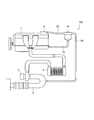
- FIG. 1 is a configuration diagram of a blow-by gas recirculation apparatus according to an embodiment of the present invention.
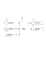
- FIG. 2 is a block diagram of the blow-by gas recirculation device.
- FIG. 3 is a perspective view of the oil separator, the upstream pipe, and the downstream pipe in the blow-by gas recirculation device.
- FIG. 4 is a side view of FIG.
- FIG. 5 is a plan view of FIG.
- blow-by gas recirculation apparatus 100 according to an embodiment of the present invention will be described with reference to the drawings.
- the internal combustion engine 1 is a diesel engine operated using light oil as fuel.
- the internal combustion engine 1 is not limited to a diesel engine, and may be a gasoline engine that is operated using gasoline as fuel. Air taken into the intake passage 2 from the atmosphere is supplied to the internal combustion engine 1 via the turbocharger 3 and the intercooler 4.
- Exhaust gas generated in a combustion chamber (not shown) of the internal combustion engine 1 is discharged to the outside through an exhaust passage (not shown) through a turbocharger 3 and a catalyst (not shown).
- the turbocharger 3 has a turbine (not shown) that is rotated by the pressure of the exhaust gas in the exhaust passage, compresses the air in the intake passage 2 and supplies the compressed air to the combustion chamber of the internal combustion engine 1.
- the internal combustion engine 1 is provided with an engine speed sensor 7 (see FIG. 2) that detects the speed.
- blow-by gas including exhaust gas and unburned gas leaks into a crankcase (not shown) from a gap between a piston (not shown) and a cylinder (not shown).
- the blow-by gas recirculation device 100 separates and removes oil such as engine oil from the blow-by gas leaked into the crankcase, and recirculates it to the intake passage 2.
- the blow-by gas joins the air flowing through the intake passage 2 and is supplied to the combustion chamber again, and is prevented from being released into the atmosphere as it is.
- the internal combustion engine 1 further includes an oil trap 8 for removing a certain amount of oil from the blow-by gas before being guided to the blow-by gas recirculation device 100.
- the internal combustion engine 1 is controlled by the control unit 40 (see FIG. 2).
- the internal combustion engine 1 is provided with an EGR (Exhaust Gas Recirculation) device (not shown).
- the EGR device guides part of the exhaust gas after combustion in the combustion chamber as EGR gas from the exhaust passage to the intake passage 2 and supplies it again to the combustion chamber. As a result, the oxygen concentration in the intake air decreases and the combustion temperature decreases, so that the generation of NOx (nitrogen oxide) during combustion is suppressed.
- the EGR device is provided with an EGR temperature sensor 6 (see FIG. 2) that detects the temperature of the EGR gas.
- the control unit 40 is composed of a microcomputer having a CPU (Central Processing Unit), ROM (Read Only Memory), RAM (Random Access Memory), and I / O interface (input / output interface).
- the RAM stores data in the processing of the CPU
- the ROM stores a control program of the CPU in advance
- the I / O interface is used for input / output of information with the connected device.
- the blow-by gas recirculation device 100 is attached to the internal combustion engine 1 to separate an oil component contained in the blow-by gas, and the blow-by gas containing the oil is separated from the internal combustion engine 1. 10, an upstream pipe 20 that leads to 10, and a downstream pipe 30 that guides blow-by gas from the oil separator 10 to the intake passage 2.
- the blow-by gas in the crankcase of the internal combustion engine 1 is guided to the oil separator 10 through the upstream pipe 20.
- the oil separator 10 passes through a filter (not shown) provided inside to separate and remove the oil from the blow-by gas.
- the oil separated by the oil separator 10 is returned to the crankcase of the internal combustion engine 1 through the oil return pipe 15.
- the blow-by gas from which oil has been removed by the oil separator 10 is guided to the intake passage 2 through the downstream pipe 30.
- the oil separator 10 does not have a filter, but may be of other types such as a labyrinth type or a cyclone type.
- the oil separator 10 includes a main body 11 formed in a substantially cylindrical shape, an inlet pipe 12 to which an upstream pipe 20 is connected, and an outlet pipe 13 to which a downstream pipe 30 is connected.
- the inlet pipe 12 and the outlet pipe 13 are formed so as to protrude from the outer periphery of the main body 11 into a substantially horizontal L shape.
- the inlet pipe 12 is provided at a lower position than the outlet pipe 13 when the oil separator 10 is attached to the internal combustion engine 1. Thereby, the blow-by gas supplied from the inlet pipe 12 flows upward in the oil separator 10, and the oil removed by the filter flows downward due to gravity. Therefore, it is prevented that the removed oil is mixed into the blow-by gas again.
- the outlet pipe 13 is provided with a pressure detector 14 (see FIG. 2).
- the pressure detector 14 is provided upstream of the connection portion between the downstream pipe 30 and the outlet pipe 13.
- the pressure detector 14 detects the pressure of the blow-by gas inside the downstream pipe 30 and outputs a corresponding electrical signal to the control unit 40.
- the pressure detector 14 detects the pressure of blow-by gas guided through the branch pipe 13 a provided in the outlet pipe 13.
- the upstream pipe 20 is attached to the oil separator 10 so that the inlet pipe 12 is inserted into the inner periphery.
- the upstream pipe 20 has an attachment portion 21 that is attached to the internal combustion engine 1 and restricts movement in the connection direction to the oil separator 10.
- the upstream pipe 20 is made of a hard oil resistant resin. Therefore, the upstream pipe 20 maintains its shape without being deformed.
- the mounting portion 21 is a bracket that is fixed between the EGR temperature sensor 6 and the internal combustion engine 1 by mounting the EGR temperature sensor 6 as an accessory to the internal combustion engine 1.
- the auxiliary machine is not limited to the EGR temperature sensor 6 and may be any detector that outputs an electrical signal to the control unit 40 that controls the internal combustion engine 1.
- the control unit 40 does not permit the rotation of the cell motor 5 of the internal combustion engine 1 when the electric signal from the EGR temperature sensor 6 is not detected. That is, the control unit 40 does not start the internal combustion engine 1 unless the pressure detector 14 is properly attached.
- the downstream pipe 30 is attached to the oil separator 10 so that the outlet pipe 13 is inserted into the inner periphery.
- the downstream pipe 30 is made of a material having higher flexibility than the upstream pipe 20. Therefore, even if the internal combustion engine 1 and the intake passage 2 vibrate differently, the relative displacement can be absorbed by the deformation of the downstream pipe 30.
- the control unit 40 determines whether or not the pressure of the blow-by gas inside the downstream pipe 30 is normal based on the rotational speed of the internal combustion engine 1 and the electrical signal from the pressure detector 14. Outputs a warning signal.
- the prescribed range in which it is determined that the blowby gas pressure is normal is set in advance to the blowby gas pressure according to the rotational speed of the internal combustion engine 1 when the blowby gas is not leaking.
- the internal combustion engine 1 includes a turbocharger 3. Therefore, the pressure in the intake passage 2 becomes negative as the rotational speed of the internal combustion engine 1 increases, and it becomes easy to detect that the pressure is not normal.
- the blow-by gas recirculation device 100 warns the driver when the pressure of the blow-by gas detected by the pressure detector 14 is not within a predetermined range set in advance, that is, when the pressure is not normal (see FIG. 2). Is provided.
- the warning device 9 is activated by a warning signal from the control unit 40. Specifically, the warning device 9 receives a warning signal from the control unit 40 and notifies the driver that the pressure of the blow-by gas inside the downstream pipe 30 is not normal.
- the warning device 9 is, for example, a warning light provided in the meter panel of the driver seat, a warning buzzer provided in the driver seat, or the like.
- blow-by gas leaks into the crankcase from the gap between the piston and the cylinder.
- the blow-by gas is guided to the oil separator 10 through the upstream pipe 20 after a certain amount of oil is removed by the oil trap 8.
- the oil separator 10 separates and removes oil from blow-by gas by a filter provided inside.
- blow-by gas from which oil has been removed by the oil separator 10 is returned to the intake passage 2, and the separated oil is returned to the crankcase through the oil return pipe 15.
- the blow-by gas recirculation device 100 prevents the blow-by gas from being released into the atmosphere as it is.
- the upstream side pipe 20 may come off from the inlet pipe 12 and the blow-by gas may leak out.
- the oil separator 10 is attached to the internal combustion engine 1, and the attachment portion 21 of the upstream pipe 20 is attached to the internal combustion engine 1. Therefore, since the oil separator 10 and the upstream pipe 20 are both attached to the internal combustion engine 1, movement of the upstream pipe 20 in the connecting direction to the oil separator 10 is restricted.
- the attachment portion 21 is fixed between the EGR temperature sensor 6 and the internal combustion engine 1 when the EGR temperature sensor 6 is attached to the internal combustion engine 1. Therefore, if the EGR temperature sensor 6 is attached, the upstream pipe 20 is correctly fixed.
- the blow-by gas recirculation device 100 does not permit the rotation of the cell motor 5 (see FIG. 2) of the internal combustion engine 1 when the electric signal from the EGR temperature sensor 6 is not detected. Therefore, since the internal combustion engine 1 does not start unless the upstream pipe 20 is properly attached, it is possible to prevent the blow-by gas from leaking due to the upstream pipe 20 not being fixed correctly.
- downstream side piping 30 when the downstream side piping 30 is insufficiently attached, for example, the downstream side piping 30 may be disconnected from the outlet piping 13 or the intake passage 2 due to vibration or the like, and blow-by gas may leak to the outside.
- the pressure detector 14 is provided upstream of the connection portion between the downstream pipe 30 and the outlet pipe 13.
- the control unit 40 determines whether or not the pressure of the blow-by gas inside the downstream pipe 30 is normal based on the rotational speed of the internal combustion engine 1 and the electrical signal from the pressure detector 14. Outputs a warning signal.
- the warning device 9 receives a warning signal from the control unit 40 and notifies the driver that the pressure of the blow-by gas inside the downstream pipe 30 is not normal. Therefore, when the downstream pipe 30 is disconnected, a warning signal is notified to the driver from the warning device 9, so that it is possible to prevent the internal combustion engine 1 from being operated with the blowby gas leaking from the blowby gas recirculation device 100. .
- the oil separator 10 is attached to the internal combustion engine 1, and the attachment portion 21 of the upstream pipe 20 is attached to the internal combustion engine 1. Therefore, since the oil separator 10 and the upstream pipe 20 are both attached to the internal combustion engine 1, movement of the upstream pipe 20 in the connecting direction to the oil separator 10 is restricted.
- the attachment portion 21 is fixed between the EGR temperature sensor 6 and the internal combustion engine 1 when the EGR temperature sensor 6 is attached to the internal combustion engine 1. Therefore, if the EGR temperature sensor 6 is attached, the upstream pipe 20 is correctly fixed.
- the blow-by gas recirculation device 100 does not allow the rotation of the cell motor 5 of the internal combustion engine 1 when the electric signal from the EGR temperature sensor 6 is not detected.
- the pressure detector 14 is provided upstream of the connection portion between the downstream pipe 30 and the outlet pipe 13.
- the control unit 40 determines whether or not the pressure of the blow-by gas inside the downstream pipe 30 is normal based on the rotational speed of the internal combustion engine 1 and the electrical signal from the pressure detector 14. Outputs a warning signal.
- the warning device 9 receives a warning signal from the control unit 40 and notifies the driver that the pressure of the blow-by gas inside the downstream pipe 30 is not normal.
Landscapes
- Engineering & Computer Science (AREA)
- Mechanical Engineering (AREA)
- General Engineering & Computer Science (AREA)
- Lubrication Details And Ventilation Of Internal Combustion Engines (AREA)
Abstract
内燃機関のブローバイガスを吸気通路に還流させるブローバイガス還流装置は、前記内燃機関に取り付けられ、ブローバイガスに含まれる油分を分離させる油分分離機(10)と、油分が含まれたブローバイガスを前記内燃機関から前記油分分離機(10)に導く上流側配管(20)と、前記油分分離機(10)からブローバイガスを前記吸気通路に導く下流側配管(30)と、を備える。前記上流側配管(20)は、前記内燃機関に取り付けられて前記油分分離機(10)への接続方向の移動を規制する取付部(21)を有する。
Description
本発明は、内燃機関のブローバイガスを吸気通路に還流させるブローバイガス還流装置に関するものである。
従来から、内燃機関の内部で発生するブローバイガスを吸気通路に還流させるブローバイガス還流装置が用いられている。
JP2012-251497Aには、内燃機関のシリンダヘッドカバーに設置されるオイルセパレータを備えるブローバイガス処理装置が開示されている。この装置では、内燃機関の吸気系へ繋がる吸気系ホースによって、オイルセパレータにて油分が除去された後のブローバイガスを吸気通路に還流している。
しかしながら、JP2012-251497Aに記載のブローバイガス処理装置では、吸気系ホースが外れたり損傷したりすると、ブローバイガスが大気中に漏出するおそれがある。同様に、内燃機関とオイルセパレータとの間を配管で接続する構成の場合にも、配管が外れたり損傷したりすると、油分を含んだブローバイガスが大気中に漏出するおそれがある。
本発明は、ブローバイガス還流装置からのブローバイガスの漏出を防止することを目的とする。
本発明のある態様によれば、内燃機関のブローバイガスを吸気通路に還流させるブローバイガス還流装置は、前記内燃機関に取り付けられ、ブローバイガスに含まれる油分を分離させる油分分離機と、油分が含まれたブローバイガスを前記内燃機関から前記油分分離機に導く上流側配管と、前記油分分離機からブローバイガスを前記吸気通路に導く下流側配管と、を備える。前記上流側配管は、前記内燃機関に取り付けられて前記油分分離機への接続方向の移動を規制する取付部を有する。
以下、図面を参照して、本発明の実施の形態に係るブローバイガス還流装置100について説明する。
まず、図1及び図2を参照して、ブローバイガス還流装置100が適用される内燃機関1について説明する。
内燃機関1は、軽油を燃料として運転されるディーゼルエンジンである。内燃機関1は、ディーゼルエンジンに限らず、ガソリンを燃料として運転されるガソリンエンジンなどであってもよい。内燃機関1には、大気中から吸気通路2に取り込まれた空気が、ターボチャージャ3とインタークーラ4とを介して供給される。
内燃機関1の燃焼室(図示省略)にて発生した排気ガスは、排気通路(図示省略)からターボチャージャ3や触媒(図示省略)等を介して外部へ排出される。ターボチャージャ3は、排気通路内の排気ガスの圧力によって回転するタービン(図示省略)を有し、吸気通路2内の空気を圧縮して内燃機関1の燃焼室に供給する。内燃機関1には、回転数を検出するエンジン回転数センサ7(図2参照)が設けられる。
内燃機関1では、排気ガスや未燃焼ガスなどを含むブローバイガスが、ピストン(図示省略)とシリンダ(図示省略)との間隙からクランクケース(図示省略)内に漏出する。ブローバイガス還流装置100は、クランクケース内に漏出したブローバイガスからエンジンオイル等の油分を分離させて取り除き、吸気通路2に還流させる。これにより、ブローバイガスは、吸気通路2を流れる空気に合流して再び燃焼室に供給され、そのままの状態で大気中に放出されることが防止される。内燃機関1は、ブローバイガス還流装置100に導かれる前にブローバイガスからある程度の油分を取り除くためのオイルトラップ8を更に備える。
内燃機関1は、制御部40(図2参照)によって制御される。また、内燃機関1には、図示しないが、EGR(Exhaust Gas Recirculation)装置が設けられる。EGR装置は、燃焼室にて燃焼した後の排気ガスの一部をEGRガスとして排気通路から吸気通路2へ導き、再び燃焼室に供給する。これにより、吸気中の酸素濃度が低下して燃焼温度が低下するため、燃焼時のNOx(窒素酸化物)の発生が抑制される。EGR装置には、EGRガスの温度を検出するEGR温度センサ6(図2参照)が設けられる。
制御部40は、CPU(中央演算処理装置)、ROM(リードオンリメモリ)、RAM(ランダムアクセスメモリ)、及びI/Oインターフェース(入出力インターフェース)を備えたマイクロコンピュータで構成される。RAMはCPUの処理におけるデータを記憶し、ROMはCPUの制御プログラム等を予め記憶し、I/Oインターフェースは接続された機器との情報の入出力に使用される。
次に、図1から図5を参照して、ブローバイガス還流装置100の構成について説明する。
図1に示すように、ブローバイガス還流装置100は、内燃機関1に取り付けられブローバイガスに含まれる油分を分離させる油分分離機10と、油分が含まれたブローバイガスを内燃機関1から油分分離機10に導く上流側配管20と、油分分離機10からブローバイガスを吸気通路2に導く下流側配管30とを備える。
油分分離機10には、内燃機関1のクランクケース内のブローバイガスが、上流側配管20を介して導かれる。油分分離機10は、内部に設けられるフィルタ(図示省略)を通過させることで、ブローバイガスから油分を分離させて除去する。油分分離機10によって分離された油分は、油分戻り配管15を通じて内燃機関1のクランクケースに戻される。一方、油分分離機10によって油分が除去されたブローバイガスは、下流側配管30を通じて吸気通路2に導かれる。油分分離機10は、フィルタを有するものではなく、ラビリンス式やサイクロン式など他の形式のものであってもよい。
図3に示すように、油分分離機10は、略円筒状に形成される本体部11と、上流側配管20が接続される入口配管12と、下流側配管30が接続される出口配管13とを有する。入口配管12と出口配管13とは、本体部11の外周から略水平なL字状に突出して形成される。
入口配管12は、油分分離機10を内燃機関1に取り付けたときに、出口配管13と比較して低い位置となるように設けられる。これにより、入口配管12から供給されたブローバイガスは、油分分離機10内を上方に流れ、フィルタによって除去された油分は重力によって下方に流下する。よって、除去された油分が再びブローバイガスに混入することが防止される。
出口配管13には、圧力検出器14(図2参照)が設けられる。圧力検出器14は、下流側配管30と出口配管13との接続部よりも上流に設けられる。圧力検出器14は、下流側配管30の内部のブローバイガスの圧力を検出して、対応する電気信号を制御部40に出力する。具体的には、圧力検出器14は、出口配管13に設けられる分岐配管13aを通じて導かれるブローバイガスの圧力を検出する。
上流側配管20は、入口配管12が内周に挿入されるように油分分離機10に取り付けられる。上流側配管20は、内燃機関1に取り付けられて油分分離機10への接続方向の移動を規制する取付部21を有する。上流側配管20は、硬質耐油性樹脂によって形成される。よって、上流側配管20は、変形せずにその形状を維持するものである。
取付部21は、内燃機関1に補機としてのEGR温度センサ6が取り付けられることによって、EGR温度センサ6と内燃機関1との間に固定されるブラケットである。補機は、EGR温度センサ6に限定されず、内燃機関1を制御する制御部40に電気信号を出力する検知器であればよい。
制御部40は、EGR温度センサ6からの電気信号を検出しない場合には、内燃機関1のセルモータ5の回転を許可しない。即ち、制御部40は、圧力検出器14が正しく取り付けられている状態でなければ、内燃機関1を始動させない。
下流側配管30は、出口配管13が内周に挿入されるように油分分離機10に取り付けられる。下流側配管30は、上流側配管20と比較して可撓性の高い材質で形成される。よって、内燃機関1と吸気通路2とが異なる振動をしても、下流側配管30の変形によって相対的な変位を吸収することができる。
制御部40は、内燃機関1の回転数と圧力検出器14からの電気信号とに基づいて下流側配管30の内部のブローバイガスの圧力が正常であるか否かを判定し、正常でない場合には警告信号を出力する。ブローバイガスの圧力が正常であると判定される規定の範囲は、ブローバイガスが漏出していない場合の内燃機関1の回転数に応じたブローバイガスの圧力に予め設定される。内燃機関1は、ターボチャージャ3を備える。そのため、内燃機関1の回転数が上昇するほど吸気通路2の圧力は負圧になり、正常でないことの検出が容易になる。
ブローバイガス還流装置100は、圧力検出器14によって検出されたブローバイガスの圧力が予め設定された規定の範囲内にない場合、即ち正常でない場合に運転者に警告する警告装置9(図2参照)を備える。
警告装置9は、制御部40からの警告信号によって作動する。具体的には、警告装置9は、制御部40からの警告信号を受けて、下流側配管30の内部のブローバイガスの圧力が正常でないことを運転者に伝達する。警告装置9は、例えば、運転席のメーターパネル内に設けられる警告灯や、運転席内に設けられる警告ブザー等である。
次に、ブローバイガス還流装置100の作用について説明する。
内燃機関1を運転すると、ピストンとシリンダとの間隙からブローバイガスがクランクケース内に漏出する。ブローバイガスは、オイルトラップ8にてある程度の油分が取り除かれた後、上流側配管20を通じて油分分離機10に導かれる。油分分離機10は、内部に設けられるフィルタによって、ブローバイガスから油分を分離させて除去する。
油分分離機10によって油分が除去されたブローバイガスは吸気通路2に還流され、分離された油分は油分戻り配管15を通じてクランクケースに戻される。このように、ブローバイガス還流装置100は、ブローバイガスがそのままの状態で大気中に放出されることを防止している。
ここで、例えば、メンテナンス後などの状況において、上流側配管20が正しく固定されていない場合には、入口配管12から上流側配管20が外れてブローバイガスが外部に漏出するおそれがある。
これに対して、ブローバイガス還流装置100では、油分分離機10が内燃機関1に取り付けられ、上流側配管20の取付部21が内燃機関1に取り付けられる。よって、油分分離機10と上流側配管20とがともに内燃機関1に取り付けられるため、上流側配管20の油分分離機10への接続方向の移動が規制される。取付部21は、内燃機関1にEGR温度センサ6が取り付けられる際に、EGR温度センサ6と内燃機関1との間に固定される。そのため、EGR温度センサ6が取り付けられていれば、上流側配管20が正しく固定されていることとなる。
ブローバイガス還流装置100では、EGR温度センサ6からの電気信号を検出しない場合には、内燃機関1のセルモータ5(図2参照)の回転を許可しない。よって、上流側配管20が正しく取り付けられていなければ内燃機関1は始動しないため、上流側配管20が正しく固定されていないことに起因してブローバイガスが漏出することを防止できる。
また、下流側配管30の取り付けが不充分である場合には、例えば、振動等によって下流側配管30が出口配管13や吸気通路2から外れて、ブローバイガスが外部に漏出するおそれがある。
これに対して、ブローバイガス還流装置100では、下流側配管30と出口配管13との接続部よりも上流に圧力検出器14が設けられる。制御部40は、内燃機関1の回転数と圧力検出器14からの電気信号とに基づいて下流側配管30の内部のブローバイガスの圧力が正常であるか否かを判定し、正常でない場合には警告信号を出力する。
警告装置9は、制御部40からの警告信号を受けて、下流側配管30の内部のブローバイガスの圧力が正常でないことを運転者に伝達する。よって、下流側配管30が外れている場合には警告装置9から警告信号が運転者に通知されるため、ブローバイガス還流装置100からブローバイガスが漏出したまま内燃機関1を運転することを防止できる。
以上の実施の形態によれば、以下に示す効果を奏する。
ブローバイガス還流装置100では、油分分離機10が内燃機関1に取り付けられ、上流側配管20の取付部21が内燃機関1に取り付けられる。よって、油分分離機10と上流側配管20とがともに内燃機関1に取り付けられるため、上流側配管20の油分分離機10への接続方向の移動が規制される。
取付部21は、内燃機関1にEGR温度センサ6が取り付けられる際に、EGR温度センサ6と内燃機関1との間に固定される。そのため、EGR温度センサ6が取り付けられていれば、上流側配管20が正しく固定されていることとなる。ブローバイガス還流装置100では、EGR温度センサ6からの電気信号を検出しない場合には、内燃機関1のセルモータ5の回転を許可しない。
したがって、上流側配管20が外れている場合には内燃機関1が始動しないため、ブローバイガス還流装置100からブローバイガスが漏出することを防止できる。
また、下流側配管30と出口配管13との接続部よりも上流に圧力検出器14が設けられる。制御部40は、内燃機関1の回転数と圧力検出器14からの電気信号とに基づいて下流側配管30の内部のブローバイガスの圧力が正常であるか否かを判定し、正常でない場合には警告信号を出力する。警告装置9は、制御部40からの警告信号を受けて、下流側配管30の内部のブローバイガスの圧力が正常でないことを運転者に伝達する。
したがって、下流側配管30が外れている場合には警告装置9から警告信号が運転者に通知されるため、ブローバイガス還流装置100からブローバイガスが漏出したまま内燃機関1を運転することを防止できる。
以上、本発明の実施形態について説明したが、上記実施形態は本発明の適用例の一部を示したに過ぎず、本発明の技術的範囲を上記実施形態の具体的構成に限定する趣旨ではない。
本願は2013年12月25日に日本国特許庁に出願された特願2013-266711に基づく優先権を主張し、この出願の全ての内容は参照により本明細書に組み込まれる。
Claims (6)
- 内燃機関のブローバイガスを吸気通路に還流させるブローバイガス還流装置であって、
前記内燃機関に取り付けられ、ブローバイガスに含まれる油分を分離させる油分分離機と、
油分が含まれたブローバイガスを前記内燃機関から前記油分分離機に導く上流側配管と、
前記油分分離機からブローバイガスを前記吸気通路に導く下流側配管と、を備え、
前記上流側配管は、前記内燃機関に取り付けられて前記油分分離機への接続方向の移動を規制する取付部を有するブローバイガス還流装置。 - 請求項1に記載のブローバイガス還流装置であって、
前記取付部は、前記内燃機関に補機が取り付けられることによって、前記補器と前記内燃機関との間に固定されるブローバイガス還流装置。 - 請求項2に記載のブローバイガス還流装置であって、
前記補機は、前記内燃機関を制御する制御部に電気信号を出力する検知器であり、
前記制御部は、前記検知器からの電気信号を検出しない場合には前記内燃機関を始動させないブローバイガス還流装置。 - 請求項1から3のいずれか一つに記載のブローバイガス還流装置であって、
前記上流側配管は、硬質耐油性樹脂によって形成されるブローバイガス還流装置。 - 請求項4に記載のブローバイガス還流装置であって、
前記下流側配管は、前記上流側配管と比較して可撓性の高い材質で形成されるブローバイガス還流装置。 - 請求項1から5のいずれか一つに記載のブローバイガス還流装置であって、
前記下流側配管と前記油分分離機との接続部よりも上流に設けられ、前記下流側配管の内部のブローバイガスの圧力を検出して前記制御部に電気信号を出力する圧力検出器を更に備え、
前記制御部は、前記内燃機関の回転数と前記圧力検出器からの電気信号とに基づいて前記下流側配管の内部のブローバイガスの圧力が正常であるか否かを判定し、正常でない場合には警告信号を出力するブローバイガス還流装置。
Applications Claiming Priority (2)
| Application Number | Priority Date | Filing Date | Title |
|---|---|---|---|
| JP2013266711A JP6399427B2 (ja) | 2013-12-25 | 2013-12-25 | ブローバイガス還流装置 |
| JP2013-266711 | 2013-12-25 |
Publications (1)
| Publication Number | Publication Date |
|---|---|
| WO2015098941A1 true WO2015098941A1 (ja) | 2015-07-02 |
Family
ID=53478792
Family Applications (1)
| Application Number | Title | Priority Date | Filing Date |
|---|---|---|---|
| PCT/JP2014/084109 Ceased WO2015098941A1 (ja) | 2013-12-25 | 2014-12-24 | ブローバイガス還流装置 |
Country Status (2)
| Country | Link |
|---|---|
| JP (1) | JP6399427B2 (ja) |
| WO (1) | WO2015098941A1 (ja) |
Cited By (1)
| Publication number | Priority date | Publication date | Assignee | Title |
|---|---|---|---|---|
| FR3128000A1 (fr) * | 2021-10-12 | 2023-04-14 | Psa Automobiles Sa | Ensemble mecanique avec detrompeur de montage de tuyau |
Families Citing this family (2)
| Publication number | Priority date | Publication date | Assignee | Title |
|---|---|---|---|---|
| JP6996463B2 (ja) | 2018-09-21 | 2022-01-17 | 株式会社豊田自動織機 | シリンダヘッドカバー及びシリンダヘッドカバーの製造方法 |
| JP6795636B2 (ja) * | 2019-02-08 | 2020-12-02 | 本田技研工業株式会社 | 内燃機関の異常判定装置 |
Citations (3)
| Publication number | Priority date | Publication date | Assignee | Title |
|---|---|---|---|---|
| JPH10205320A (ja) * | 1997-01-24 | 1998-08-04 | Yanmar Diesel Engine Co Ltd | 内燃機関のミストセパレーター |
| JP2013092078A (ja) * | 2011-10-25 | 2013-05-16 | Ud Trucks Corp | ブローバイガスの配管系統 |
| JP2013124587A (ja) * | 2011-12-14 | 2013-06-24 | Ud Trucks Corp | ガス配管 |
Family Cites Families (10)
| Publication number | Priority date | Publication date | Assignee | Title |
|---|---|---|---|---|
| JPH044807Y2 (ja) * | 1986-12-26 | 1992-02-12 | ||
| JPH0351121U (ja) * | 1989-09-26 | 1991-05-17 | ||
| JPH03107382U (ja) * | 1990-02-20 | 1991-11-05 | ||
| JP2696500B2 (ja) * | 1995-03-31 | 1998-01-14 | ヤマハ発動機株式会社 | エンジンのブローバイガス用油分離装置 |
| JPH10169426A (ja) * | 1996-12-10 | 1998-06-23 | Zexel Corp | エンジン保護装置 |
| JP2004100526A (ja) * | 2002-09-06 | 2004-04-02 | Honda Motor Co Ltd | 内燃機関のスロットル弁制御装置 |
| JP2005002862A (ja) * | 2003-06-11 | 2005-01-06 | Suzuki Motor Corp | エンジンのヒータパイプの固定構造 |
| JP4475082B2 (ja) * | 2004-09-29 | 2010-06-09 | 井関農機株式会社 | エンジン |
| JP5580178B2 (ja) * | 2010-11-29 | 2014-08-27 | ヤンマー株式会社 | エンジン装置 |
| JP6087053B2 (ja) * | 2011-12-01 | 2017-03-01 | Udトラックス株式会社 | ブローバイガス還元装置及びブローバイガス還元装置の異常診断方法 |
-
2013
- 2013-12-25 JP JP2013266711A patent/JP6399427B2/ja not_active Expired - Fee Related
-
2014
- 2014-12-24 WO PCT/JP2014/084109 patent/WO2015098941A1/ja not_active Ceased
Patent Citations (3)
| Publication number | Priority date | Publication date | Assignee | Title |
|---|---|---|---|---|
| JPH10205320A (ja) * | 1997-01-24 | 1998-08-04 | Yanmar Diesel Engine Co Ltd | 内燃機関のミストセパレーター |
| JP2013092078A (ja) * | 2011-10-25 | 2013-05-16 | Ud Trucks Corp | ブローバイガスの配管系統 |
| JP2013124587A (ja) * | 2011-12-14 | 2013-06-24 | Ud Trucks Corp | ガス配管 |
Cited By (2)
| Publication number | Priority date | Publication date | Assignee | Title |
|---|---|---|---|---|
| FR3128000A1 (fr) * | 2021-10-12 | 2023-04-14 | Psa Automobiles Sa | Ensemble mecanique avec detrompeur de montage de tuyau |
| WO2023062295A1 (fr) * | 2021-10-12 | 2023-04-20 | Psa Automobiles Sa | Ensemble mecanique avec detrompeur de montage de tuyau |
Also Published As
| Publication number | Publication date |
|---|---|
| JP2015121195A (ja) | 2015-07-02 |
| JP6399427B2 (ja) | 2018-10-03 |
Similar Documents
| Publication | Publication Date | Title |
|---|---|---|
| US11047329B2 (en) | Method and device for diagnosing a crankcase ventilation line for an internal combustion engine | |
| CN107532544B (zh) | 内燃机以及用于识别曲轴箱通风系统和/或燃料箱通风系统的泄漏的方法 | |
| JP6223211B2 (ja) | エンジンの低圧ループ式排気還流装置 | |
| US9714590B2 (en) | Crankcase integrity breach detection | |
| US9260990B2 (en) | Crankcase integrity breach detection | |
| US10619534B2 (en) | Crankcase integrity breach detection | |
| US9068486B2 (en) | Crankcase integrity breach detection | |
| US9416694B2 (en) | Crankcase integrity breach detection | |
| JP4688770B2 (ja) | 排出ガス再循環装置を持つエンジンの制御装置及び制御方法 | |
| JP6087053B2 (ja) | ブローバイガス還元装置及びブローバイガス還元装置の異常診断方法 | |
| US10436158B2 (en) | Abnormality detection device for humidity sensor | |
| JP2019019800A (ja) | 低圧ループ式egr装置を備えた過給機付きエンジンにおけるブローバイガス還元装置の異常診断装置 | |
| US9932924B2 (en) | Abnormality diagnosis device for blow-by gas returning apparatus | |
| JP6399427B2 (ja) | ブローバイガス還流装置 | |
| JP2018091179A (ja) | 故障診断装置および故障診断方法 | |
| JP2020012436A (ja) | エンジンシステム | |
| JP2010242617A (ja) | 内燃機関の異常検出システム | |
| JP6354714B2 (ja) | 過給機付き内燃機関の異常診断装置 | |
| JP6043477B2 (ja) | ブローバイガス還元装置及びブローバイガス還元装置の異常診断方法 | |
| JP6424637B2 (ja) | 内燃機関の故障防止システム、内燃機関及び内燃機関の故障防止方法 | |
| JP5228820B2 (ja) | エアクリーナ装置 | |
| CN115244282B (zh) | 内燃机的异常诊断方法以及内燃机的异常诊断装置 | |
| US10927731B2 (en) | Cylinder head cover and method of manufacturing the cylinder head cover | |
| US9207142B2 (en) | Engine ventilation system diagnostics using pressure measurement | |
| JP5577836B2 (ja) | 内燃機関のブローバイガス処理装置 |
Legal Events
| Date | Code | Title | Description |
|---|---|---|---|
| 121 | Ep: the epo has been informed by wipo that ep was designated in this application |
Ref document number: 14874021 Country of ref document: EP Kind code of ref document: A1 |
|
| NENP | Non-entry into the national phase |
Ref country code: DE |
|
| 122 | Ep: pct application non-entry in european phase |
Ref document number: 14874021 Country of ref document: EP Kind code of ref document: A1 |