JP6996463B2 - シリンダヘッドカバー及びシリンダヘッドカバーの製造方法 - Google Patents
シリンダヘッドカバー及びシリンダヘッドカバーの製造方法 Download PDFInfo
- Publication number
- JP6996463B2 JP6996463B2 JP2018176978A JP2018176978A JP6996463B2 JP 6996463 B2 JP6996463 B2 JP 6996463B2 JP 2018176978 A JP2018176978 A JP 2018176978A JP 2018176978 A JP2018176978 A JP 2018176978A JP 6996463 B2 JP6996463 B2 JP 6996463B2
- Authority
- JP
- Japan
- Prior art keywords
- path
- cylinder head
- main body
- head cover
- gas
- Prior art date
- Legal status (The legal status is an assumption and is not a legal conclusion. Google has not performed a legal analysis and makes no representation as to the accuracy of the status listed.)
- Active
Links
- 238000004519 manufacturing process Methods 0.000 title claims description 24
- 238000002485 combustion reaction Methods 0.000 claims description 54
- 238000005520 cutting process Methods 0.000 claims description 28
- 238000000034 method Methods 0.000 claims description 12
- 239000011347 resin Substances 0.000 claims description 7
- 229920005989 resin Polymers 0.000 claims description 7
- 239000002184 metal Substances 0.000 claims description 6
- 238000001514 detection method Methods 0.000 description 36
- 238000011144 upstream manufacturing Methods 0.000 description 16
- 239000002826 coolant Substances 0.000 description 5
- 238000000465 moulding Methods 0.000 description 5
- 239000000446 fuel Substances 0.000 description 4
- 238000003860 storage Methods 0.000 description 4
- 238000004080 punching Methods 0.000 description 3
- 239000003054 catalyst Substances 0.000 description 2
- 238000001816 cooling Methods 0.000 description 2
- 238000005336 cracking Methods 0.000 description 2
- 238000002474 experimental method Methods 0.000 description 2
- 238000000746 purification Methods 0.000 description 2
- 238000004088 simulation Methods 0.000 description 2
- 238000007792 addition Methods 0.000 description 1
- 238000012217 deletion Methods 0.000 description 1
- 230000037430 deletion Effects 0.000 description 1
- 238000007599 discharging Methods 0.000 description 1
- 230000007613 environmental effect Effects 0.000 description 1
- 239000010419 fine particle Substances 0.000 description 1
- 230000003647 oxidation Effects 0.000 description 1
- 238000007254 oxidation reaction Methods 0.000 description 1
- 238000005086 pumping Methods 0.000 description 1
- 230000004043 responsiveness Effects 0.000 description 1
- 238000004092 self-diagnosis Methods 0.000 description 1
Images


Classifications
-
- F—MECHANICAL ENGINEERING; LIGHTING; HEATING; WEAPONS; BLASTING
- F01—MACHINES OR ENGINES IN GENERAL; ENGINE PLANTS IN GENERAL; STEAM ENGINES
- F01M—LUBRICATING OF MACHINES OR ENGINES IN GENERAL; LUBRICATING INTERNAL COMBUSTION ENGINES; CRANKCASE VENTILATING
- F01M13/00—Crankcase ventilating or breathing
- F01M13/04—Crankcase ventilating or breathing having means for purifying air before leaving crankcase, e.g. removing oil
- F01M13/0416—Crankcase ventilating or breathing having means for purifying air before leaving crankcase, e.g. removing oil arranged in valve-covers
-
- F—MECHANICAL ENGINEERING; LIGHTING; HEATING; WEAPONS; BLASTING
- F01—MACHINES OR ENGINES IN GENERAL; ENGINE PLANTS IN GENERAL; STEAM ENGINES
- F01M—LUBRICATING OF MACHINES OR ENGINES IN GENERAL; LUBRICATING INTERNAL COMBUSTION ENGINES; CRANKCASE VENTILATING
- F01M13/00—Crankcase ventilating or breathing
- F01M13/02—Crankcase ventilating or breathing by means of additional source of positive or negative pressure
- F01M13/021—Crankcase ventilating or breathing by means of additional source of positive or negative pressure of negative pressure
- F01M13/022—Crankcase ventilating or breathing by means of additional source of positive or negative pressure of negative pressure using engine inlet suction
-
- F—MECHANICAL ENGINEERING; LIGHTING; HEATING; WEAPONS; BLASTING
- F02—COMBUSTION ENGINES; HOT-GAS OR COMBUSTION-PRODUCT ENGINE PLANTS
- F02M—SUPPLYING COMBUSTION ENGINES IN GENERAL WITH COMBUSTIBLE MIXTURES OR CONSTITUENTS THEREOF
- F02M25/00—Engine-pertinent apparatus for adding non-fuel substances or small quantities of secondary fuel to combustion-air, main fuel or fuel-air mixture
- F02M25/06—Engine-pertinent apparatus for adding non-fuel substances or small quantities of secondary fuel to combustion-air, main fuel or fuel-air mixture adding lubricant vapours
-
- F—MECHANICAL ENGINEERING; LIGHTING; HEATING; WEAPONS; BLASTING
- F01—MACHINES OR ENGINES IN GENERAL; ENGINE PLANTS IN GENERAL; STEAM ENGINES
- F01M—LUBRICATING OF MACHINES OR ENGINES IN GENERAL; LUBRICATING INTERNAL COMBUSTION ENGINES; CRANKCASE VENTILATING
- F01M13/00—Crankcase ventilating or breathing
- F01M13/02—Crankcase ventilating or breathing by means of additional source of positive or negative pressure
- F01M13/021—Crankcase ventilating or breathing by means of additional source of positive or negative pressure of negative pressure
- F01M2013/027—Crankcase ventilating or breathing by means of additional source of positive or negative pressure of negative pressure with a turbo charger or compressor
-
- Y—GENERAL TAGGING OF NEW TECHNOLOGICAL DEVELOPMENTS; GENERAL TAGGING OF CROSS-SECTIONAL TECHNOLOGIES SPANNING OVER SEVERAL SECTIONS OF THE IPC; TECHNICAL SUBJECTS COVERED BY FORMER USPC CROSS-REFERENCE ART COLLECTIONS [XRACs] AND DIGESTS
- Y02—TECHNOLOGIES OR APPLICATIONS FOR MITIGATION OR ADAPTATION AGAINST CLIMATE CHANGE
- Y02T—CLIMATE CHANGE MITIGATION TECHNOLOGIES RELATED TO TRANSPORTATION
- Y02T10/00—Road transport of goods or passengers
- Y02T10/10—Internal combustion engine [ICE] based vehicles
- Y02T10/12—Improving ICE efficiencies
Landscapes
- Engineering & Computer Science (AREA)
- Mechanical Engineering (AREA)
- General Engineering & Computer Science (AREA)
- Chemical & Material Sciences (AREA)
- Combustion & Propulsion (AREA)
- Cylinder Crankcases Of Internal Combustion Engines (AREA)
- Lubrication Details And Ventilation Of Internal Combustion Engines (AREA)
Description
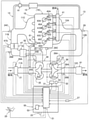
以下に本発明を実施するための形態を図面を用いて説明する。まず図1を用いて、内燃機関10のシステム全体の概略構成の例について説明する。本実施の形態の説明では、内燃機関の例として、車両に搭載された内燃機関10(例えばディーゼルエンジン)を用いて説明する。
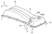
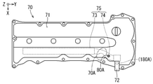
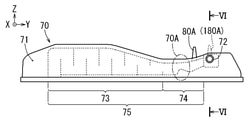
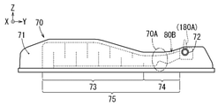
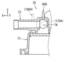
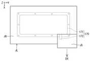
次に図2~図6を用いて、シリンダヘッドカバー70の外観と構造等について説明する。図2に示すように、シリンダヘッドカバー70は、本体部71と、側方突出部72とを有しており、本体部71と側方突出部72は、樹脂または金属で形成された型成形品である。なお図2~図6中において点線で示す符号(180A)は、比較を容易にするために、従来のシリンダヘッドカバーにおける突出分岐路の位置を示しており、本実施の形態における突出分岐路80Aの位置を示すものではない。
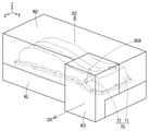
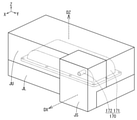
次に図7、図8を用いて、シリンダヘッドカバー70の製造方法について説明する。シリンダヘッドカバー70の本体部71と、突出分岐路80A(または孔部80B)と、側方突出部72は、樹脂または金属の型成形品であって一体成形品とされている。
11A、11B 吸気管
11C 吸気マニホルド
12A 排気マニホルド
12B、12C 排気管
13 EGR配管
14 EGR弁
15 EGRクーラ
21 吸気流量検出手段
22 回転検出手段
23 大気圧検出手段
24A コンプレッサ上流圧力検出手段
24B コンプレッサ下流圧力検出手段
24C 圧力検出手段
25 アクセルペダル踏込量検出手段
26A タービン上流圧力検出手段
26B タービン下流圧力検出手段
27 車速検出手段
28A、28B 吸気温度検出手段
28C クーラント温度検出手段
29 排気温度検出手段
30 ターボ過給機
31 ノズル駆動手段
32 ノズル開度検出手段
33 可変ノズル
35 コンプレッサ
35A コンプレッサインペラ
36 タービン
36A タービンインペラ
41 コモンレール
43A~43D インジェクタ
45A~45D シリンダ
47 スロットル装置
47S スロットル開度検出手段
50 制御装置
51 制御手段
53 記憶手段
61 排気浄化装置
70 シリンダヘッドカバー
70A 経路断面積最小部
71 本体部
72 側方突出部
73 ラビリンス経路部
74 接続経路部
75 本体部内ガス経路
80A 突出分岐路
80B 孔部
81 圧力検出手段
82 (ブローバイガス還流用)配管
DX 側方型抜き方向
DZ 本体型抜き方向
KU 一方型
KL 他方型
KS 側方型
Claims (6)
- 内燃機関内にて発生したブローバイガスを前記内燃機関から吸気経路に流すブローバイガス還流システムにおけるシリンダヘッドカバーであって、
前記シリンダヘッドカバーは、樹脂または金属の型成形品であって前記内燃機関のシリンダヘッドを覆うように設けられてブローバイガスが集められる本体部と、前記本体部の側方に突出するように設けられてブローバイガスを前記吸気経路に向けて吐出する側方突出部と、を有しており、
前記側方突出部と前記吸気経路とは配管にて接続され、
前記本体部は、集められたブローバイガスを前記側方突出部まで導くとともに所定の経路断面積を有する本体部内ガス経路を有しており、
前記本体部内ガス経路から前記側方突出部の出口までのブローバイガスが流れる経路であるカバー内ガス経路において、経路の断面積が最小となる経路断面積最小部は、前記側方突出部ではなく前記本体部内ガス経路に設けられており、
前記本体部における前記経路断面積最小部の位置よりも下流側となる前記本体部内ガス経路の位置に、前記本体部内ガス経路内の圧力を検出する圧力検出手段を前記本体部の外側から取り付けるための孔部、または前記圧力検出手段を前記本体部の外側から接続するための突出分岐路、が形成されており、
前記本体部と、前記側方突出部と、前記孔部または前記突出分岐路は、一体成形品とされている、
シリンダヘッドカバー。 - 請求項1に記載のシリンダヘッドカバーであって、
前記孔部が形成されている場合、前記内燃機関に前記シリンダヘッドカバーを取り付けた際に前記孔部は、前記シリンダヘッドとは反対の側に配置されて、前記シリンダヘッドとは反対の側に開口するように形成されており、
前記突出分岐路が形成されている場合、前記内燃機関に前記シリンダヘッドカバーを取り付けた際に前記突出分岐路は、前記シリンダヘッドとは反対の側に配置されて、前記シリンダヘッドとは反対の側に突出するように形成されている、
シリンダヘッドカバー。 - 請求項1または2に記載のシリンダヘッドカバーであって、
前記本体部内ガス経路は、迷路状に経路が形成されたラビリンス経路部と、前記ラビリンス経路部の終端から前記側方突出部までを接続する接続経路部と、を有しており、
前記経路断面積最小部と、前記孔部または前記突出分岐路と、が前記接続経路部に設けられている、
シリンダヘッドカバー。 - 請求項1~3のいずれか一項に記載のシリンダヘッドカバーであって、
前記内燃機関に前記シリンダヘッドカバーを取り付けた際の前記シリンダヘッドカバーにおける前記シリンダヘッドの側から前記シリンダヘッドとは反対の側に向かう方向の高さをシリンダヘッドカバー高さとした場合、
前記経路断面積最小部は、前記シリンダヘッドカバー高さが周囲の前記シリンダヘッドカバー高さよりも低くなっている前記シリンダヘッドカバーの個所に設けられている、
シリンダヘッドカバー。 - 内燃機関内にて発生したブローバイガスを前記内燃機関から吸気経路に流すブローバイガス還流システムにおけるシリンダヘッドカバーの製造方法であって、
前記シリンダヘッドカバーは、樹脂または金属の型成形品であり、前記内燃機関のシリンダヘッドを覆うように設けられてブローバイガスが集められる本体部と、前記本体部の側方に突出するように設けられてブローバイガスを前記吸気経路に向けて吐出する側方突出部と、を有し、
前記本体部に、集められたブローバイガスを前記側方突出部まで導くとともに所定の経路断面積を有する本体部内ガス経路を設定し、
前記本体部内ガス経路から前記側方突出部の出口までのブローバイガスが流れる経路であるカバー内ガス経路において、経路の断面積が最小となる経路断面積最小部を、前記側方突出部ではなく前記本体部内ガス経路に設定し、
前記本体部における前記経路断面積最小部の位置よりも下流側となる前記本体部内ガス経路の位置に、前記本体部内ガス経路内の圧力を検出する圧力検出手段を前記本体部の外側から取り付けるための孔部、または前記圧力検出手段を前記本体部の外側から接続するための突出分岐路、を設定し、
前記本体部と、前記孔部または突出分岐路とを、少なくとも一方が本体型抜き方向に沿って移動可能な一方型と他方型の少なくとも一方にて形成し、
前記側方突出部を、前記側方突出部の軸線方向であって前記本体型抜き方向とは異なる方向である側方型抜き方向に移動可能な側方型にて形成することで、前記本体部と、前記孔部または前記突出分岐路と、前記側方突出部と、を一体成形する、
シリンダヘッドカバーの製造方法。 - 請求項5に記載のシリンダヘッドカバーの製造方法であって、
前記本体型抜き方向を上方向に設定し、
前記一方型を前記他方型の上方に配置し、
前記孔部または前記突出分岐路を、前記一方型にて形成する、
シリンダヘッドカバーの製造方法。
Priority Applications (3)
| Application Number | Priority Date | Filing Date | Title |
|---|---|---|---|
| JP2018176978A JP6996463B2 (ja) | 2018-09-21 | 2018-09-21 | シリンダヘッドカバー及びシリンダヘッドカバーの製造方法 |
| US16/565,795 US10927731B2 (en) | 2018-09-21 | 2019-09-10 | Cylinder head cover and method of manufacturing the cylinder head cover |
| BR102019019499-5A BR102019019499A2 (pt) | 2018-09-21 | 2019-09-19 | Tampa de cabeçote de cilindro e método de fabricação tampa de cabeçote de cilindro |
Applications Claiming Priority (1)
| Application Number | Priority Date | Filing Date | Title |
|---|---|---|---|
| JP2018176978A JP6996463B2 (ja) | 2018-09-21 | 2018-09-21 | シリンダヘッドカバー及びシリンダヘッドカバーの製造方法 |
Publications (2)
| Publication Number | Publication Date |
|---|---|
| JP2020045881A JP2020045881A (ja) | 2020-03-26 |
| JP6996463B2 true JP6996463B2 (ja) | 2022-01-17 |
Family
ID=69884015
Family Applications (1)
| Application Number | Title | Priority Date | Filing Date |
|---|---|---|---|
| JP2018176978A Active JP6996463B2 (ja) | 2018-09-21 | 2018-09-21 | シリンダヘッドカバー及びシリンダヘッドカバーの製造方法 |
Country Status (3)
| Country | Link |
|---|---|
| US (1) | US10927731B2 (ja) |
| JP (1) | JP6996463B2 (ja) |
| BR (1) | BR102019019499A2 (ja) |
Families Citing this family (1)
| Publication number | Priority date | Publication date | Assignee | Title |
|---|---|---|---|---|
| JP7559787B2 (ja) * | 2022-03-03 | 2024-10-02 | トヨタ自動車株式会社 | 内燃機関 |
Citations (3)
| Publication number | Priority date | Publication date | Assignee | Title |
|---|---|---|---|---|
| CN202520396U (zh) | 2012-03-27 | 2012-11-07 | 重庆长安汽车股份有限公司 | 一种发动机缸盖罩的通气管 |
| JP2015048752A (ja) | 2013-08-30 | 2015-03-16 | アイシン精機株式会社 | センサ支持構造 |
| JP2015113763A (ja) | 2013-12-11 | 2015-06-22 | 愛知機械工業株式会社 | カム角センサ取付具及び内燃機関 |
Family Cites Families (12)
| Publication number | Priority date | Publication date | Assignee | Title |
|---|---|---|---|---|
| JPS62145916U (ja) * | 1986-03-07 | 1987-09-14 | ||
| JPH03172524A (ja) * | 1989-11-30 | 1991-07-25 | Toyota Autom Loom Works Ltd | Pcvルーム内の異常圧力を検知してエンジンのトラブルを防止する機構 |
| US6098603A (en) * | 1996-12-24 | 2000-08-08 | Denso Corporation | Blow-by gas passage abnormality detecting system for internal combustion engines |
| US20020184042A1 (en) * | 2001-06-01 | 2002-12-05 | Freemarkets, Inc. | Method, apparatus, and system for grouping transportation services |
| JP4960763B2 (ja) * | 2007-05-16 | 2012-06-27 | 本田技研工業株式会社 | 内燃機関のヘッドカバー |
| DE102013208231A1 (de) * | 2013-05-06 | 2014-11-06 | Mahle International Gmbh | Zylinderkopfhaube |
| JP6146202B2 (ja) * | 2013-08-22 | 2017-06-14 | トヨタ紡織株式会社 | オイルミストセパレータ |
| JP6399427B2 (ja) | 2013-12-25 | 2018-10-03 | ボルボトラックコーポレーション | ブローバイガス還流装置 |
| JP2015140679A (ja) * | 2014-01-27 | 2015-08-03 | アイシン精機株式会社 | オイルセパレータ |
| JP2017219014A (ja) * | 2016-06-10 | 2017-12-14 | ヤマハ発動機株式会社 | エンジンのブローバイガス用気液分離装置 |
| JP6528810B2 (ja) * | 2017-07-14 | 2019-06-12 | マツダ株式会社 | エンジンのシリンダヘッドカバー構造 |
| JP2019132232A (ja) * | 2018-02-01 | 2019-08-08 | トヨタ自動車株式会社 | 内燃機関のブローバイガス処理装置 |
-
2018
- 2018-09-21 JP JP2018176978A patent/JP6996463B2/ja active Active
-
2019
- 2019-09-10 US US16/565,795 patent/US10927731B2/en not_active Expired - Fee Related
- 2019-09-19 BR BR102019019499-5A patent/BR102019019499A2/pt active Search and Examination
Patent Citations (3)
| Publication number | Priority date | Publication date | Assignee | Title |
|---|---|---|---|---|
| CN202520396U (zh) | 2012-03-27 | 2012-11-07 | 重庆长安汽车股份有限公司 | 一种发动机缸盖罩的通气管 |
| JP2015048752A (ja) | 2013-08-30 | 2015-03-16 | アイシン精機株式会社 | センサ支持構造 |
| JP2015113763A (ja) | 2013-12-11 | 2015-06-22 | 愛知機械工業株式会社 | カム角センサ取付具及び内燃機関 |
Also Published As
| Publication number | Publication date |
|---|---|
| US20200095911A1 (en) | 2020-03-26 |
| US10927731B2 (en) | 2021-02-23 |
| BR102019019499A2 (pt) | 2020-03-31 |
| JP2020045881A (ja) | 2020-03-26 |
Similar Documents
| Publication | Publication Date | Title |
|---|---|---|
| JP4215069B2 (ja) | 内燃機関の排気還流装置 | |
| JP5527486B2 (ja) | 内燃機関の換気制御装置 | |
| EP3290667B1 (en) | Blowby gas treatment device for internal combustion engine with supercharger | |
| JP2008150955A (ja) | 排気還流装置 | |
| JP2006336547A (ja) | Egr装置 | |
| JP6996463B2 (ja) | シリンダヘッドカバー及びシリンダヘッドカバーの製造方法 | |
| JP2009185751A (ja) | 内燃機関の制御装置 | |
| US10697358B2 (en) | Intake passage structure for turbocharger-equipped engine | |
| CN106481427B (zh) | 发动机的排气装置 | |
| JP2013096229A (ja) | ブローバイガス還流装置 | |
| US8479510B2 (en) | Exhaust gas recirculation system | |
| JP4793245B2 (ja) | 内燃機関の排気還流装置 | |
| JP2009108701A (ja) | 内燃機関の排気還流装置 | |
| JP2006009745A (ja) | 内燃機関のエアフローセンサ出力補正方法 | |
| US10408120B2 (en) | Opening/closing valve structure | |
| US11643945B2 (en) | Internal combustion engine diagnosing device | |
| JPWO2018069975A1 (ja) | ターボ過給機付エンジンの吸気通路構造 | |
| JP2013221488A (ja) | 過給機付き内燃機関の制御装置 | |
| JP2009209816A (ja) | 内燃機関の制御装置 | |
| JPH10103168A (ja) | 内燃エンジンの排出ガス再循環装置 | |
| JP2008208721A (ja) | 内燃機関の排気還流装置 | |
| JP6328519B2 (ja) | ブローバイガス還元装置と過給機を備えたエンジンの排気還流装置 | |
| JP4798497B2 (ja) | 内燃機関におけるセンサ洗浄装置 | |
| JP5577836B2 (ja) | 内燃機関のブローバイガス処理装置 | |
| JP2012246891A (ja) | 過給機付内燃機関の吸気装置 |
Legal Events
| Date | Code | Title | Description |
|---|---|---|---|
| A621 | Written request for application examination |
Free format text: JAPANESE INTERMEDIATE CODE: A621 Effective date: 20201218 |
|
| TRDD | Decision of grant or rejection written | ||
| A977 | Report on retrieval |
Free format text: JAPANESE INTERMEDIATE CODE: A971007 Effective date: 20211110 |
|
| A01 | Written decision to grant a patent or to grant a registration (utility model) |
Free format text: JAPANESE INTERMEDIATE CODE: A01 Effective date: 20211116 |
|
| A61 | First payment of annual fees (during grant procedure) |
Free format text: JAPANESE INTERMEDIATE CODE: A61 Effective date: 20211129 |
|
| R151 | Written notification of patent or utility model registration |
Ref document number: 6996463 Country of ref document: JP Free format text: JAPANESE INTERMEDIATE CODE: R151 |