JP6996463B2 - Manufacturing method of cylinder head cover and cylinder head cover - Google Patents
Manufacturing method of cylinder head cover and cylinder head cover Download PDFInfo
- Publication number
- JP6996463B2 JP6996463B2 JP2018176978A JP2018176978A JP6996463B2 JP 6996463 B2 JP6996463 B2 JP 6996463B2 JP 2018176978 A JP2018176978 A JP 2018176978A JP 2018176978 A JP2018176978 A JP 2018176978A JP 6996463 B2 JP6996463 B2 JP 6996463B2
- Authority
- JP
- Japan
- Prior art keywords
- path
- cylinder head
- main body
- head cover
- gas
- Prior art date
- Legal status (The legal status is an assumption and is not a legal conclusion. Google has not performed a legal analysis and makes no representation as to the accuracy of the status listed.)
- Active
Links
- 238000004519 manufacturing process Methods 0.000 title claims description 24
- 238000002485 combustion reaction Methods 0.000 claims description 54
- 238000005520 cutting process Methods 0.000 claims description 28
- 238000000034 method Methods 0.000 claims description 12
- 239000011347 resin Substances 0.000 claims description 7
- 229920005989 resin Polymers 0.000 claims description 7
- 239000002184 metal Substances 0.000 claims description 6
- 238000001514 detection method Methods 0.000 description 36
- 238000011144 upstream manufacturing Methods 0.000 description 16
- 239000002826 coolant Substances 0.000 description 5
- 238000000465 moulding Methods 0.000 description 5
- 239000000446 fuel Substances 0.000 description 4
- 238000003860 storage Methods 0.000 description 4
- 238000004080 punching Methods 0.000 description 3
- 239000003054 catalyst Substances 0.000 description 2
- 238000001816 cooling Methods 0.000 description 2
- 238000005336 cracking Methods 0.000 description 2
- 238000002474 experimental method Methods 0.000 description 2
- 238000000746 purification Methods 0.000 description 2
- 238000004088 simulation Methods 0.000 description 2
- 238000007792 addition Methods 0.000 description 1
- 238000012217 deletion Methods 0.000 description 1
- 230000037430 deletion Effects 0.000 description 1
- 238000007599 discharging Methods 0.000 description 1
- 230000007613 environmental effect Effects 0.000 description 1
- 239000010419 fine particle Substances 0.000 description 1
- 230000003647 oxidation Effects 0.000 description 1
- 238000007254 oxidation reaction Methods 0.000 description 1
- 238000005086 pumping Methods 0.000 description 1
- 230000004043 responsiveness Effects 0.000 description 1
- 238000004092 self-diagnosis Methods 0.000 description 1
Images


Classifications
-
- F—MECHANICAL ENGINEERING; LIGHTING; HEATING; WEAPONS; BLASTING
- F01—MACHINES OR ENGINES IN GENERAL; ENGINE PLANTS IN GENERAL; STEAM ENGINES
- F01M—LUBRICATING OF MACHINES OR ENGINES IN GENERAL; LUBRICATING INTERNAL COMBUSTION ENGINES; CRANKCASE VENTILATING
- F01M13/00—Crankcase ventilating or breathing
- F01M13/04—Crankcase ventilating or breathing having means for purifying air before leaving crankcase, e.g. removing oil
- F01M13/0416—Crankcase ventilating or breathing having means for purifying air before leaving crankcase, e.g. removing oil arranged in valve-covers
-
- F—MECHANICAL ENGINEERING; LIGHTING; HEATING; WEAPONS; BLASTING
- F01—MACHINES OR ENGINES IN GENERAL; ENGINE PLANTS IN GENERAL; STEAM ENGINES
- F01M—LUBRICATING OF MACHINES OR ENGINES IN GENERAL; LUBRICATING INTERNAL COMBUSTION ENGINES; CRANKCASE VENTILATING
- F01M13/00—Crankcase ventilating or breathing
- F01M13/02—Crankcase ventilating or breathing by means of additional source of positive or negative pressure
- F01M13/021—Crankcase ventilating or breathing by means of additional source of positive or negative pressure of negative pressure
- F01M13/022—Crankcase ventilating or breathing by means of additional source of positive or negative pressure of negative pressure using engine inlet suction
-
- F—MECHANICAL ENGINEERING; LIGHTING; HEATING; WEAPONS; BLASTING
- F02—COMBUSTION ENGINES; HOT-GAS OR COMBUSTION-PRODUCT ENGINE PLANTS
- F02M—SUPPLYING COMBUSTION ENGINES IN GENERAL WITH COMBUSTIBLE MIXTURES OR CONSTITUENTS THEREOF
- F02M25/00—Engine-pertinent apparatus for adding non-fuel substances or small quantities of secondary fuel to combustion-air, main fuel or fuel-air mixture
- F02M25/06—Engine-pertinent apparatus for adding non-fuel substances or small quantities of secondary fuel to combustion-air, main fuel or fuel-air mixture adding lubricant vapours
-
- F—MECHANICAL ENGINEERING; LIGHTING; HEATING; WEAPONS; BLASTING
- F01—MACHINES OR ENGINES IN GENERAL; ENGINE PLANTS IN GENERAL; STEAM ENGINES
- F01M—LUBRICATING OF MACHINES OR ENGINES IN GENERAL; LUBRICATING INTERNAL COMBUSTION ENGINES; CRANKCASE VENTILATING
- F01M13/00—Crankcase ventilating or breathing
- F01M13/02—Crankcase ventilating or breathing by means of additional source of positive or negative pressure
- F01M13/021—Crankcase ventilating or breathing by means of additional source of positive or negative pressure of negative pressure
- F01M2013/027—Crankcase ventilating or breathing by means of additional source of positive or negative pressure of negative pressure with a turbo charger or compressor
-
- Y—GENERAL TAGGING OF NEW TECHNOLOGICAL DEVELOPMENTS; GENERAL TAGGING OF CROSS-SECTIONAL TECHNOLOGIES SPANNING OVER SEVERAL SECTIONS OF THE IPC; TECHNICAL SUBJECTS COVERED BY FORMER USPC CROSS-REFERENCE ART COLLECTIONS [XRACs] AND DIGESTS
- Y02—TECHNOLOGIES OR APPLICATIONS FOR MITIGATION OR ADAPTATION AGAINST CLIMATE CHANGE
- Y02T—CLIMATE CHANGE MITIGATION TECHNOLOGIES RELATED TO TRANSPORTATION
- Y02T10/00—Road transport of goods or passengers
- Y02T10/10—Internal combustion engine [ICE] based vehicles
- Y02T10/12—Improving ICE efficiencies
Landscapes
- Engineering & Computer Science (AREA)
- Mechanical Engineering (AREA)
- General Engineering & Computer Science (AREA)
- Chemical & Material Sciences (AREA)
- Combustion & Propulsion (AREA)
- Cylinder Crankcases Of Internal Combustion Engines (AREA)
- Lubrication Details And Ventilation Of Internal Combustion Engines (AREA)
Description
本発明は、内燃機関のシリンダヘッドカバー、及び当該シリンダヘッドカバーの製造方法に関する。 The present invention relates to a cylinder head cover of an internal combustion engine and a method for manufacturing the cylinder head cover.
内燃機関の内部ではブローバイガスが発生しており、当該ブローバイガスを吸気経路に流すブローバイガス還流システムが構成されている。ブローバイガスは、燃料を含んだガスであるため、環境上の観点から、大気中に放出するべきではないため、一旦、内燃機関のシリンダヘッドカバーに集め、配管を介してシリンダヘッドカバーから吸気経路へ流し、内燃機関で燃焼させている。内燃機関の運転時の吸気経路では負圧が発生しているので、当該負圧にてブローバイガスをシリンダヘッドカバーから吸気経路に吸引している。 Blow-by gas is generated inside the internal combustion engine, and a blow-by gas recirculation system for flowing the blow-by gas to the intake path is configured. Since blow-by gas is a gas containing fuel and should not be released into the atmosphere from an environmental point of view, it is once collected in the cylinder head cover of an internal combustion engine and flowed from the cylinder head cover to the intake path through a pipe. , Burning in an internal combustion engine. Since a negative pressure is generated in the intake path during operation of the internal combustion engine, blow-by gas is sucked from the cylinder head cover to the intake path at the negative pressure.
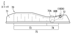
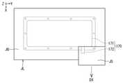
図9に、従来のシリンダヘッドカバー170の例を示す。なお、図中にX軸、Y軸、Z軸が記載されている場合、X軸とY軸とZ軸は互いに直交しており、Z軸方向は鉛直上向き方向を示し、X軸方向とY軸方向は水平方向を示している。またY軸方向はシリンダヘッドカバーの長手方向を示している。シリンダヘッドカバー170は、樹脂等の型成形品であり、本体部171、側方突出部172、ラビリンス経路部173、接続経路部174、突出分岐路180A等を有している。本体部171は、内燃機関のシリンダヘッドを覆うように設けられ、内燃機関内で発生したブローバイガスを集め、集めたブローバイガスをラビリンス経路部173と接続経路部174を経由させて側方突出部172へと導く。ラビリンス経路部173は、所定の経路断面積を有して迷路状とされたブローバイガスの流れる経路であり、ブローバイガス中の油分等を分離する。接続経路部174は、所定の経路断面積を有してラビリンス経路部173の出口部と側方突出部172の入口部とを接続している。側方突出部172は、筒状の形状を有して本体部171の側方から突出しており、シリンダヘッドカバー170からのブローバイガスを吸気経路に導くための配管182が接続されている。なお、側方突出部172は、無理抜き製法にて作られている。
FIG. 9 shows an example of the conventional
なお、シリンダヘッドカバー170の側方突出部172と吸気経路とに接続された配管182に、割れ、亀裂、脱落等が発生した場合、ブローバイガスが大気中に漏れるので、当該配管182の割れ、亀裂、脱落等を検出する必要がある。前記配管182の割れ、亀裂、脱落等の検出には、配管182の上流側の圧力が利用されている。具体的には、シリンダヘッドカバー170からのブローバイガスの出口に相当する側方突出部172に、圧力検出手段の検出用配管を接続するための突出分岐路180Aを設け、当該突出分岐路を介して側方突出部172内の圧力を検出することで、配管182の割れ、亀裂、脱落等の発生を検出している。
If cracks, cracks, drops, etc. occur in the
また特許文献1には、上記のラビリンス経路部に相当するPCVルームを有するシリンダヘッドカバーが記載されている。特許文献1に記載のシリンダヘッドカバーでは、自身から吐出されるブローバイガスを吸気経路へ導く配管が、PCVルームの出口部に接続されており、PCVルームには、PCVルーム内の圧力を検出する圧力センサが接続されている。 Further, Patent Document 1 describes a cylinder head cover having a PCV room corresponding to the above-mentioned labyrinth path portion. In the cylinder head cover described in Patent Document 1, a pipe for guiding blow-by gas discharged from itself to the intake path is connected to the outlet portion of the PCV room, and the pressure in the PCV room is detected in the PCV room. The sensor is connected.
また特許文献2には、上記のラビリンス経路部に相当する油分分離機がシリンダヘッドカバーとは別体とされたブローバイガス還流装置が記載されている。特許文献2に記載のシリンダヘッドカバーでは、別体とされた油分分離機がシリンダヘッドカバーの外部に固定され、シリンダヘッドカバーと油分分離機は上流側配管にて接続され、油分分離機と吸気経路は下流側配管にて接続されている。また、油分分離機における下流側配管との接続部である分離機出口配管には、圧力検出器に接続するための分岐配管が設けられている。 Further, Patent Document 2 describes a blow-by gas recirculation device in which the oil separator corresponding to the labyrinth path portion is separated from the cylinder head cover. In the cylinder head cover described in Patent Document 2, a separate oil separator is fixed to the outside of the cylinder head cover, the cylinder head cover and the oil separator are connected by an upstream pipe, and the oil separator and the intake path are downstream. It is connected by a side pipe. Further, the separator outlet pipe, which is a connection portion with the downstream pipe in the oil separator, is provided with a branch pipe for connecting to the pressure detector.
図9に示す従来のシリンダヘッドカバーを製造する場合、一般的には、図10及び図11に示すように、下方型JL(金型等)と上方型JU(金型等)にて本体部171を形成し、側方型JS(金型等)にて側方突出部172を形成する。この場合、側方型JSの型抜き方向である側方型抜き方向DXは、筒状の側方突出部172の突出方向であり、図10及び図11の場合では、側方型抜き方向DXはX軸方向にほぼ平行となる。また下方型JLと上方型JUの型抜き方向である本体型抜き方向DZは上下方向であり、図10及び図11の場合では、本体型抜き方向DZはZ軸方向にほぼ平行となる。また、下方型JL、上方型JU、側方型JSにて一体成形されたシリンダヘッドカバー170は、図9に示す突出分岐路180Aと、ラビリンス経路部173と、を有していない。ラビリンス経路部173は迷路状の複雑な形状であるので、シリンダヘッドカバー170とは別体で組み立てられて、一体成形されたシリンダヘッドカバー170に取り付けられている(図12)。また突出分岐路180Aの突出方向は、図10及び図11に示す側方型抜き方向DXと平行ではないので、側方型JSにて側方突出部172と突出分岐路180Aとを一体成形することができないため、別体とされている。このため、側方型JSでは突出分岐路180Aを有していない側方突出部172を形成しなければならず、本体部171と側方突出部172を一体成形品として形成した後、側方突出部172に突出分岐路180Aを溶着またはネジ止め等している(図12)。
When manufacturing the conventional cylinder head cover shown in FIG. 9, generally, as shown in FIGS. 10 and 11, the
配管182(図9参照)の割れ、亀裂、脱落等を検出するために配管182内の圧力を精度良く検出するには、側方突出部172内の圧力を検出する必要があると考えられていたため、突出分岐路180Aは側方突出部172に設ける必要があると考えられていた。しかし、上述したように側方型JS(図10、図11参照)を用いて側方突出部172を形成した場合、側方突出部172と突出分岐路180Aとを一体成形することができないため、突出分岐路180Aを別体として溶着またはネジ止め等しなければならず、部品点数及び製造工程が増加していた。突出分岐路180Aは単純な形状であり、側方突出部172または本体部171と一体成形することで、部品点数及び製造工程を低減することが望まれている。
In order to accurately detect the pressure inside the
また特許文献1に記載されているシリンダヘッドカバーには、PCVルーム内の圧力を検出する圧力センサが設けられている。しかし、シリンダヘッドカバーと吸気経路を接続する配管の割れ、亀裂、脱落等を検出するための圧力検出手段に関する記載は見受けられず、当該配管の割れ、亀裂、脱落等を検出するための圧力検出手段が設けられていない。 Further, the cylinder head cover described in Patent Document 1 is provided with a pressure sensor for detecting the pressure in the PCV room. However, there is no description about the pressure detecting means for detecting the crack, crack, falling off, etc. of the pipe connecting the cylinder head cover and the intake path, and the pressure detecting means for detecting the cracking, cracking, falling off, etc. of the pipe. Is not provided.
また特許文献2に記載されているシリンダヘッドカバーでは、油分分離機における分離機出口配管に接続された圧力検出器にて下流側配管の割れ、亀裂、脱落等を検出することはできるが、上流側配管の割れ、亀裂、脱落等を検出することはできない。また、油分分離機を別体で設けているため、シリンダヘッドカバーと吸気経路を接続する配管が、上流側配管と下流側配管に分かれて部品点数が増加している。 Further, in the cylinder head cover described in Patent Document 2, a pressure detector connected to the outlet pipe of the separator in the oil separator can detect cracks, cracks, falling off, etc. of the pipe on the downstream side, but on the upstream side. It is not possible to detect cracks, cracks, drops, etc. in pipes. Further, since the oil separator is provided separately, the piping connecting the cylinder head cover and the intake path is divided into upstream piping and downstream piping, and the number of parts is increasing.
本発明は、このような点に鑑みて創案されたものであり、ブローバイガス還流システムにおけるシリンダヘッドカバーにおいて、シリンダヘッドカバーと吸気経路とを接続するブローバイガス還流用の配管の割れ、亀裂、脱落等を適切に検出することが可能であり、かつ、部品点数と製造工程をより低減することができるシリンダヘッドカバー及びシリンダヘッドカバーの製造方法を提供することを課題とする。 The present invention has been devised in view of these points, and in the cylinder head cover in the blow-by gas recirculation system, cracks, cracks, drops, etc. of the blow-by gas recirculation pipe connecting the cylinder head cover and the intake path are prevented. An object of the present invention is to provide a cylinder head cover and a method for manufacturing a cylinder head cover, which can be appropriately detected and can further reduce the number of parts and the manufacturing process.
上記課題を解決するため、本発明の第1の発明は、内燃機関内にて発生したブローバイガスを前記内燃機関から吸気経路に流すブローバイガス還流システムにおけるシリンダヘッドカバーであって、前記シリンダヘッドカバーは、樹脂または金属の型成形品であって前記内燃機関のシリンダヘッドを覆うように設けられてブローバイガスが集められる本体部と、前記本体部の側方に突出するように設けられてブローバイガスを前記吸気経路に向けて吐出する側方突出部と、を有しており、前記側方突出部と前記吸気経路とは配管にて接続され、前記本体部は、集められたブローバイガスを前記側方突出部まで導くとともに所定の経路断面積を有する本体部内ガス経路を有しており、前記本体部内ガス経路から前記側方突出部の出口までのブローバイガスが流れる経路であるカバー内ガス経路において、経路の断面積が最小となる経路断面積最小部は、前記側方突出部ではなく前記本体部内ガス経路に設けられており、前記本体部における前記経路断面積最小部の位置よりも下流側となる前記本体部内ガス経路の位置に、前記本体部内ガス経路内の圧力を検出する圧力検出手段を前記本体部の外側から取り付けるための孔部、または前記圧力検出手段を前記本体部の外側から接続するための突出分岐路、が形成されており、前記本体部と、前記側方突出部と、前記孔部または前記突出分岐路は、一体成形品とされている、シリンダヘッドカバーである。 In order to solve the above problems, the first invention of the present invention is a cylinder head cover in a blow-by gas recirculation system in which blow-by gas generated in an internal combustion engine is flowed from the internal combustion engine to an intake path. A main body portion of a resin or metal molded product that is provided so as to cover the cylinder head of the internal combustion engine and collects blow-by gas, and a main body portion that is provided so as to project to the side of the main body portion to provide blow-by gas. It has a lateral protrusion that discharges toward the intake path, the lateral protrusion and the intake path are connected by a pipe, and the main body portion receives the collected blow-by gas laterally. In the gas path in the cover, which has a gas path in the main body having a predetermined path cross-sectional area while guiding to the protruding portion, and is a path through which blow-by gas flows from the gas path in the main body to the outlet of the lateral protruding portion. The path cross-sectional area minimum portion that minimizes the cross-sectional area of the path is provided not in the lateral protrusion but in the gas path in the main body portion, and is located on the downstream side of the position of the path cross-sectional area minimum portion in the main body portion. At the position of the gas path in the main body, a hole for attaching a pressure detecting means for detecting the pressure in the gas path in the main body from the outside of the main body, or the pressure detecting means is connected from the outside of the main body. A protruding branch path is formed, and the main body portion, the side projecting portion, the hole portion, or the protruding branch path is a cylinder head cover which is an integrally molded product.
次に、本発明の第2の発明は、上記第1の発明に係るシリンダヘッドカバーであって、前記孔部が形成されている場合、前記内燃機関に前記シリンダヘッドカバーを取り付けた際に前記孔部は、前記シリンダヘッドとは反対の側に配置されて、前記シリンダヘッドとは反対の側に開口するように形成されており、前記突出分岐路が形成されている場合、前記内燃機関に前記シリンダヘッドカバーを取り付けた際に前記突出分岐路は、前記シリンダヘッドとは反対の側に配置されて、前記シリンダヘッドとは反対の側に突出するように形成されている、シリンダヘッドカバーである。 Next, the second invention of the present invention is the cylinder head cover according to the first invention, and when the hole is formed, the hole is formed when the cylinder head cover is attached to the internal combustion engine. Is arranged on the side opposite to the cylinder head and is formed so as to open on the side opposite to the cylinder head, and when the protruding branch path is formed, the cylinder is connected to the internal combustion engine. When the head cover is attached, the protruding branch path is a cylinder head cover that is arranged on the side opposite to the cylinder head and is formed so as to project to the side opposite to the cylinder head.
次に、本発明の第3の発明は、上記第1の発明または第2の発明に係るシリンダヘッドカバーであって、前記本体部内ガス経路は、迷路状に経路が形成されたラビリンス経路部と、前記ラビリンス経路部の終端から前記側方突出部までを接続する接続経路部と、を有しており、前記経路断面積最小部と、前記孔部または前記突出分岐路と、が前記接続経路部に設けられている、シリンダヘッドカバーである。 Next, the third invention of the present invention is the cylinder head cover according to the first invention or the second invention, and the gas path in the main body is a labyrinth path portion in which a path is formed in a maze shape. It has a connection path portion that connects from the end of the labyrinth path portion to the lateral protrusion, and the connection path portion includes the minimum path cross-sectional area and the hole portion or the protrusion branch path. It is a cylinder head cover provided in.
次に、本発明の第4の発明は、上記第1の発明~第3の発明のいずれか1つに係るシリンダヘッドカバーであって、前記内燃機関に前記シリンダヘッドカバーを取り付けた際の前記シリンダヘッドカバーにおける前記シリンダヘッドの側から前記シリンダヘッドとは反対の側に向かう方向の高さをシリンダヘッドカバー高さとした場合、前記経路断面積最小部は、前記シリンダヘッドカバー高さが周囲の前記シリンダヘッドカバー高さよりも低くなっている前記シリンダヘッドカバーの個所に設けられている、シリンダヘッドカバーである。 Next, the fourth invention of the present invention is the cylinder head cover according to any one of the above first invention to the third invention, and the cylinder head cover when the cylinder head cover is attached to the internal combustion engine. When the height in the direction from the side of the cylinder head to the side opposite to the cylinder head is defined as the cylinder head cover height, the minimum path cross-sectional area is such that the cylinder head cover height is higher than the surrounding cylinder head cover height. It is a cylinder head cover provided at a position of the cylinder head cover which is also lowered.
次に、本発明の第5の発明は、内燃機関内にて発生したブローバイガスを前記内燃機関から吸気経路に流すブローバイガス還流システムにおけるシリンダヘッドカバーの製造方法であって、前記シリンダヘッドカバーは、樹脂または金属の型成形品であり、前記内燃機関のシリンダヘッドを覆うように設けられてブローバイガスが集められる本体部と、前記本体部の側方に突出するように設けられてブローバイガスを前記吸気経路に向けて吐出する側方突出部と、を有し、前記本体部に、集められたブローバイガスを前記側方突出部まで導くとともに所定の経路断面積を有する本体部内ガス経路を設定し、前記本体部内ガス経路から前記側方突出部の出口までのブローバイガスが流れる経路であるカバー内ガス経路において、経路の断面積が最小となる経路断面積最小部を、前記側方突出部ではなく前記本体部内ガス経路に設定し、前記本体部における前記経路断面積最小部の位置よりも下流側となる前記本体部内ガス経路の位置に、前記本体部内ガス経路内の圧力を検出する圧力検出手段を前記本体部の外側から取り付けるための孔部、または前記圧力検出手段を前記本体部の外側から接続するための突出分岐路、を設定し、前記本体部と、前記孔部または突出分岐路とを、少なくとも一方が本体型抜き方向に沿って移動可能な一方型と他方型の少なくとも一方にて形成し、前記側方突出部を、前記側方突出部の軸線方向であって前記本体型抜き方向とは異なる方向である側方型抜き方向に移動可能な側方型にて形成することで、前記本体部と、前記孔部または前記突出分岐路と、前記側方突出部と、を一体成形する、シリンダヘッドカバーの製造方法である。 Next, a fifth aspect of the present invention is a method for manufacturing a cylinder head cover in a blow-by gas recirculation system in which blow-by gas generated in an internal combustion engine is flowed from the internal combustion engine to an intake path, wherein the cylinder head cover is made of resin. Alternatively, it is a molded metal product, and is provided so as to cover the cylinder head of the internal combustion engine and collect blow-by gas, and the main body is provided so as to project to the side of the main body to suck the blow-by gas. It has a lateral protrusion that discharges toward the path, and a gas path in the main body that guides the collected blow-by gas to the lateral protrusion and has a predetermined path cross-sectional area is set in the main body. In the in-cover gas path, which is the path through which blow-by gas flows from the gas path in the main body to the outlet of the lateral protrusion, the path cross-sectional area minimum portion that minimizes the cross-sectional area of the path is not the lateral protrusion. A pressure detecting means that is set in the gas path in the main body and detects the pressure in the gas path in the main body at the position of the gas path in the main body that is downstream from the position of the minimum cross-sectional area of the path in the main body. A hole for attaching the main body from the outside of the main body or a protruding branch path for connecting the pressure detecting means from the outside of the main body is set, and the main body and the hole or the protruding branch are provided. Is formed by at least one of the one mold and the other mold, one of which can move along the main body die cutting direction, and the lateral protrusion is formed in the axial direction of the side protrusion and the main body die cutting. By forming the main body portion, the hole portion or the protruding branch path, and the lateral protruding portion, the main body portion, the hole portion or the protruding branch path, and the lateral protruding portion are integrated by forming a lateral mold that can be moved in a lateral die cutting direction that is a direction different from the direction. It is a method of manufacturing a cylinder head cover to be molded.
次に、本発明の第6の発明は、上記第5の発明に係るシリンダヘッドカバーの製造方法であって、前記本体型抜き方向を上方向に設定し、前記一方型を前記他方型の上方に配置し、前記孔部または前記突出分岐路を、前記一方型にて形成する、シリンダヘッドカバーの製造方法である。 Next, a sixth aspect of the present invention is the method for manufacturing a cylinder head cover according to the fifth aspect, wherein the main body die cutting direction is set upward, and the one die is placed above the other die. It is a method of manufacturing a cylinder head cover that is arranged and the hole portion or the protruding branch path is formed by the one-sided mold.
シリンダヘッドカバー内のブローバイガスを吸気経路に導くブローバイガス還流用の配管の一方端はシリンダヘッドカバーの側方突出部に接続され、他方端は吸気経路に接続されている。当該配管の割れ、亀裂、脱落等を、圧力で検出するためには、当該配管の入口部となる側方突出部内の圧力を検出する必要があると考えられていた。しかし、種々の実験やシミュレーション等によって、シリンダヘッドカバーの本体部内から側方突出部の出口までのブローバイガスが流れる経路中において、経路断面積が最小となる個所の下流で圧力を検出すれば、前記配管の割れ、亀裂、脱落等を検出可能であることがわかった。 One end of the blow-by gas recirculation pipe that guides the blow-by gas in the cylinder head cover to the intake path is connected to the lateral protrusion of the cylinder head cover, and the other end is connected to the intake path. In order to detect cracks, cracks, falling off, etc. of the pipe by pressure, it was considered necessary to detect the pressure in the lateral protrusion which is the inlet of the pipe. However, if the pressure is detected downstream of the part where the path cross-sectional area is the minimum in the path through which the blow-by gas flows from the inside of the main body of the cylinder head cover to the outlet of the lateral protrusion by various experiments and simulations, the above-mentioned It was found that cracks, cracks, and dropouts of pipes could be detected.
第1の発明では、経路断面積最小部を、側方突出部ではなく本体部内ガス経路に設けている。これにより、ブローバイガス還流用の配管の割れ、亀裂、脱落等を適切に検出することを可能とする圧力検出手段を取り付ける孔部または当該圧力検出手段を接続するための突出分岐路を、本体部における経路断面積最小部の位置よりも下流側となる本体部内ガス経路に設けることができる。そして、本体部を作る型によって本体部と突出分岐路(または孔部)を同時に成形することで、部品点数と製造工程を低減することができる。 In the first invention, the minimum path cross-sectional area is provided not in the lateral protrusion but in the gas path in the main body. As a result, a hole for attaching a pressure detecting means capable of appropriately detecting cracks, cracks, falling off, etc. of the blow-by gas recirculation pipe or a protruding branch path for connecting the pressure detecting means is provided in the main body. It can be provided in the gas path in the main body portion on the downstream side of the position of the minimum path cross-sectional area in the above. Then, by simultaneously forming the main body portion and the protruding branch path (or the hole portion) by the mold for making the main body portion, the number of parts and the manufacturing process can be reduced.
第2の発明では、孔部の配置位置及び開口方向を適切な位置及び方向とすることで、または、突出分岐路の配置位置及び突出方向を適切な位置及び方向とすることで、本体部と、孔部または突出分岐路と、をより一体成形しやすい構造とすることができる。 In the second invention, by setting the arrangement position and opening direction of the hole portion to an appropriate position and direction, or by setting the arrangement position and the projecting direction of the protruding branch path to an appropriate position and direction, the main body portion and the main body portion are used. , The hole or the protruding branch path can be made into a structure that is easier to integrally form.
第3の発明では、経路断面積最小部と、孔部または突出分岐路を、側方突出部を除いたブローバイガスの経路中(シリンダヘッドカバー内の経路中)において、ブローバイガス還流用の配管に対して、より近い位置に設定する。これにより、ブローバイガス還流用の配管の割れ、亀裂、脱落等を検出するための圧力を、より精度よく、より応答性よく検出することができる。 In the third invention, the minimum path cross-sectional area and the hole or protruding branch path are used as a pipe for blow-by gas recirculation in the blow-by gas path (in the path in the cylinder head cover) excluding the lateral protrusion. On the other hand, set it closer. As a result, the pressure for detecting cracks, cracks, falling off, etc. of the blow-by gas recirculation pipe can be detected more accurately and more responsively.
第4の発明によれば、経路断面積最小部の近傍の下流側に突出分岐路を設けた場合、シリンダヘッドカバー高さが必要以上に高くなることを抑制することが可能である。また、経路断面積最小部の近傍の下流側に孔部を設けた場合、孔部に取り付けられた圧力検出手段の突出高さを含むシリンダヘッドカバー高さが必要以上に高くなることを抑制することが可能である。従って、車両へのシリンダヘッドカバーの搭載性をより向上(省スペース化)させることができる。 According to the fourth invention, when the protruding branch path is provided on the downstream side in the vicinity of the minimum path cross-sectional area, it is possible to prevent the cylinder head cover height from becoming higher than necessary. In addition, when a hole is provided on the downstream side near the minimum path cross-sectional area, it is possible to prevent the cylinder head cover height including the protruding height of the pressure detecting means attached to the hole from becoming higher than necessary. Is possible. Therefore, the mountability of the cylinder head cover on the vehicle can be further improved (space saving).
第5の発明では、経路断面積最小部を、側方突出部ではなく本体部内ガス経路に設けている。これにより、ブローバイガス還流用の配管の割れ、亀裂、脱落等を適切に検出することを可能とする圧力検出手段を取り付ける孔部または当該圧力検出手段を接続するための突出分岐路を、本体部における経路断面積最小部の位置よりも下流側となる本体部内ガス経路に設けることができる。そして、一方型と他方型と側方型にて、本体部と、孔部または突出分岐路と、側方突出部と、を適切に一体成形することができる。これにより、部品点数と製造工程を低減することができる。 In the fifth invention, the minimum path cross-sectional area is provided not in the lateral protrusion but in the gas path in the main body. As a result, a hole for attaching a pressure detecting means capable of appropriately detecting cracks, cracks, falling off, etc. of the blow-by gas recirculation pipe or a protruding branch path for connecting the pressure detecting means is provided in the main body. It can be provided in the gas path in the main body portion on the downstream side of the position of the minimum path cross-sectional area in the above. Then, the main body portion, the hole portion or the projecting branch path, and the lateral projecting portion can be appropriately integrally molded in the one-sided mold, the other mold, and the side mold. As a result, the number of parts and the manufacturing process can be reduced.
第6の発明によれば、本体部と、孔部または突出分岐路と、を適切かつ容易に一体成形することができる。 According to the sixth invention, the main body portion and the hole portion or the protruding branch path can be appropriately and easily integrally molded.
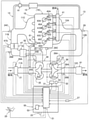
●[内燃機関10のシステム全体の概略構成の例(図1)]
以下に本発明を実施するための形態を図面を用いて説明する。まず図1を用いて、内燃機関10のシステム全体の概略構成の例について説明する。本実施の形態の説明では、内燃機関の例として、車両に搭載された内燃機関10(例えばディーゼルエンジン)を用いて説明する。
● [Example of schematic configuration of the entire system of the internal combustion engine 10 (FIG. 1)]
Hereinafter, embodiments for carrying out the present invention will be described with reference to the drawings. First, an example of a schematic configuration of the entire system of the
以下、システム全体について、吸気側から排気側に向かって順に説明する。吸気管11Aの流入側には、エアクリーナ(図示省略)、吸気流量検出手段21(例えば、吸気流量センサ)が設けられている。吸気流量検出手段21は、内燃機関10が吸入した空気の流量に応じた検出信号を制御装置50に出力する。また吸気流量検出手段21には、吸気温度検出手段28A(例えば、吸気温度センサ)が設けられている。吸気温度検出手段28Aは、吸気流量検出手段21を通過する吸気の温度に応じた検出信号を制御装置50に出力する。
Hereinafter, the entire system will be described in order from the intake side to the exhaust side. An air cleaner (not shown) and an intake flow rate detecting means 21 (for example, an intake flow rate sensor) are provided on the inflow side of the
吸気管11Aの流出側はコンプレッサ35の流入側に接続され、コンプレッサ35の流出側は吸気管11Bの流入側に接続されている。ターボ過給機30は、コンプレッサインペラ35Aを有するコンプレッサ35と、タービンインペラ36Aを有するタービン36とを備えている。コンプレッサインペラ35Aは、排気ガスによって回転駆動されるタービンインペラ36Aにて回転駆動され、吸気管11Aから流入された吸気を吸気管11Bに圧送することで過給する。
The outflow side of the
コンプレッサ35の上流側となる吸気管11Aには、コンプレッサ上流圧力検出手段24Aが設けられている。コンプレッサ上流圧力検出手段24Aは、例えば圧力センサであり、コンプレッサ35の上流側となる吸気管11A内の圧力に応じた検出信号を制御装置50に出力する。コンプレッサ35の下流側となる吸気管11B(吸気管11Bにおけるコンプレッサ35とインタークーラ16との間の位置)には、コンプレッサ下流圧力検出手段24Bが設けられている。コンプレッサ下流圧力検出手段24Bは、例えば圧力センサであり、コンプレッサ35の下流側となる吸気管11B内の圧力に応じた検出信号を制御装置50に出力する。
The
吸気管11Bには、上流側にインタークーラ16が配置され、インタークーラ16よりも下流側にスロットル装置47が配置されている。インタークーラ16は、コンプレッサ下流圧力検出手段24Bよりも下流側に配置されており、コンプレッサ35にて過給された吸気の温度を下げる。インタークーラ16とスロットル装置47との間には、吸気温度検出手段28B(例えば、吸気温度センサ)が設けられている。吸気温度検出手段28Bは、インタークーラ16にて温度が低下された吸気の温度に応じた検出信号を制御装置50に出力する。
In the
スロットル装置47は、制御装置50からの制御信号に基づいて吸気管11Bの開度を調整するスロットルバルブを駆動し、吸気流量を調整可能である。制御装置50は、スロットル開度検出手段47S(例えば、スロットル開度センサ)からの検出信号と目標スロットル開度に基づいて、スロットル装置47に制御信号を出力して吸気管11Bに設けられたスロットルバルブの開度を調整可能である。制御装置50は、アクセルペダル踏込量検出手段25からの検出信号に基づいて検出したアクセルペダルの踏込量と内燃機関10の運転状態とに基づいて目標スロットル開度を求める。
The
アクセルペダル踏込量検出手段25は、例えばアクセルペダル踏込角度センサであり、アクセルペダルに設けられている。制御装置50は、アクセルペダル踏込量検出手段25からの検出信号に基づいて、運転者によるアクセルペダルの踏込量を検出することが可能である。
The accelerator pedal depression
吸気管11Bにおけるスロットル装置47よりも下流側には、圧力検出手段24Cが設けられており、EGR配管13の流出側が接続されている。そして吸気管11Bの流出側は吸気マニホルド11Cの流入側に接続されており、吸気マニホルド11Cの流出側は内燃機関10の流入側に接続されている。圧力検出手段24Cは、例えば圧力センサであり、吸気マニホルド11Cに流入する直前の吸気の圧力に応じた検出信号を制御装置50に出力する。またEGR配管13の流出側(吸気管11Bとの接続部)からは、EGR配管13の流入側(排気管12Bとの接続部)から流入してきたEGRガスが、吸気管11B内に吐出される。なおEGR配管13にて形成されるEGRガスが流れる経路は、EGR経路に相当している。
A
内燃機関10は複数のシリンダ45A~45Dを有しており、インジェクタ43A~43Dが、それぞれのシリンダに設けられている。インジェクタ43A~43Dには、コモンレール41と燃料配管42A~42Dを介して燃料が供給されており、インジェクタ43A~43Dは、制御装置50からの制御信号によって駆動され、それぞれのシリンダ45A~45D内に燃料を噴射する。
The
内燃機関10内で発生したブローバイガスを内燃機関10から吸気経路(吸気管11A)に流すブローバイガス還流システムは、シリンダヘッドカバー70と配管82にて構成されている。内燃機関10のシリンダヘッドには、シリンダヘッドを覆うようにシリンダヘッドカバー70が取り付けられており(図2参照)、シリンダヘッドカバー70には、ブローバイガスを吐出する側方突出部72(図2参照)が設けられている。そしてシリンダヘッドカバー70の側方突出部72と吸気管11A(吸気経路に相当)は、ブローバイガス還流用の配管82にて接続されている。内燃機関10内で発生したブローバイガスは、シリンダヘッドカバー70内に集められ、側方突出部72及び配管82を介して吸気管11A(吸気経路に相当)に導かれる。吸気管11Aは、コンプレッサ35の上流側であるので、内燃機関10の運転時には負圧が発生しており、当該負圧にて配管82内のブローバイガスを吸引し、吸引されたブローバイガスは内燃機関10内で燃焼される。また、シリンダヘッドカバー70には、配管82の割れ、亀裂、脱落等を検出するための圧力検出手段81が接続されている、または取り付けられている。圧力検出手段81は、例えば圧力センサであり、配管82内の圧力に応じた検出信号を制御装置50に出力する。
The blow-by gas recirculation system for flowing the blow-by gas generated in the
内燃機関10には、回転検出手段22、クーラント温度検出手段28C等が設けられている。回転検出手段22は、例えば回転センサであり、内燃機関10のクランクシャフトの回転数(すなわち、エンジン回転数)に応じた検出信号を制御装置50に出力する。クーラント温度検出手段28Cは、例えば温度センサであり、内燃機関10内に循環されている冷却用クーラントの温度を検出し、検出した温度に応じた検出信号を制御装置50に出力する。
The
内燃機関10の排気側には排気マニホルド12Aの流入側が接続され、排気マニホルド12Aの流出側には排気管12Bの流入側が接続されている。排気管12Bの流出側はタービン36の流入側に接続され、タービン36の流出側は排気管12Cの流入側に接続されている。
The inflow side of the
排気管12Bには、EGR配管13の流入側が接続されている。EGR配管13は、排気管12Bと吸気管11Bとを連通し、排気管12B(排気経路に相当)の排気ガスの一部を吸気管11B(吸気経路に相当)に還流させることが可能である。またEGR配管13には、EGRクーラ15、EGR弁14が設けられている。
The inflow side of the
EGR弁14(EGRバルブ)は、EGR配管13におけるEGRクーラ15の下流側に設けられている。そしてEGR弁14は、制御装置50からの制御信号に基づいて、EGR配管13の開度を調整することで、EGR配管13内を流れるEGRガスの流量を調整する。
The EGR valve 14 (EGR valve) is provided on the downstream side of the
EGRクーラ15は、EGR配管13に設けられている。EGRクーラ15は、いわゆる熱交換器であり、冷却用のクーラントが供給され、流入されたEGRガスを冷却して吐出する。
The
排気管12Bには、排気温度検出手段29が設けられている。排気温度検出手段29は、例えば排気温度センサであり、排気温度に応じた検出信号を制御装置50に出力する。
The
排気管12Bの流出側はタービン36の流入側に接続され、タービン36の流出側は排気管12Cの流入側に接続されている。タービン36には、タービンインペラ36Aへ導く排気ガスの流速を制御可能な可変ノズル33が設けられており、可変ノズル33は、ノズル駆動手段31によって開度が調整される。制御装置50は、ノズル開度検出手段32(例えば、ノズル開度センサ)からの検出信号と目標ノズル開度に基づいて、ノズル駆動手段31に制御信号を出力して可変ノズル33の開度を調整可能である。
The outflow side of the
タービン36の上流側となる排気管12Bには、タービン上流圧力検出手段26Aが設けられている。タービン上流圧力検出手段26Aは、例えば圧力センサであり、タービン36の上流側となる排気管12B内の圧力に応じた検出信号を制御装置50に出力する。タービン36の下流側となる排気管12Cには、タービン下流圧力検出手段26Bが設けられている。タービン下流圧力検出手段26Bは、例えば圧力センサであり、タービン36の下流側となる排気管12C内の圧力に応じた検出信号を制御装置50に出力する。
The
排気管12Cの流出側には排気浄化装置61が接続されている。例えば内燃機関10がディーゼルエンジンの場合、排気浄化装置61には、酸化触媒、微粒子捕集フィルタ、選択式還元触媒等が含まれている。
An
制御装置50は、少なくとも、制御手段51(CPU)、記憶手段53を有している。制御装置50(制御手段51)は、図1に示す検出手段やアクチュエータに限定されず、上記の検出手段を含めた各種の検出手段からの検出信号に基づいて内燃機関10の運転状態を検出し、上記のインジェクタ43A~43DやEGR弁14、ノズル駆動手段31、スロットル装置47を含めた各種のアクチュエータを制御する。記憶手段53は、例えばFlash-ROM等の記憶装置であり、内燃機関の制御や自己診断等を実行するためのプログラムやデータ等が記憶されている。
The
大気圧検出手段23は、例えば大気圧センサであり、制御装置50に設けられている。大気圧検出手段23は、制御装置50の周囲の大気圧に応じた検出信号を制御装置50に出力する。
The atmospheric
車速検出手段27は、例えば車両速度検出センサであり、車両の車輪等に設けられている。車速検出手段27は、車両の車輪の回転速度に応じた検出信号を制御装置50に出力する。
The vehicle speed detection means 27 is, for example, a vehicle speed detection sensor, and is provided on a wheel or the like of the vehicle. The vehicle
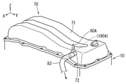
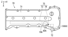
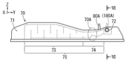
●[シリンダヘッドカバー70の外観と構造(図2~図6)]
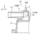
次に図2~図6を用いて、シリンダヘッドカバー70の外観と構造等について説明する。図2に示すように、シリンダヘッドカバー70は、本体部71と、側方突出部72とを有しており、本体部71と側方突出部72は、樹脂または金属で形成された型成形品である。なお図2~図6中において点線で示す符号(180A)は、比較を容易にするために、従来のシリンダヘッドカバーにおける突出分岐路の位置を示しており、本実施の形態における突出分岐路80Aの位置を示すものではない。
● [Appearance and structure of cylinder head cover 70 (FIGS. 2 to 6)]
Next, the appearance, structure, and the like of the
本体部71は、図2に示すように、内燃機関10のシリンダヘッドを覆うように設けられている。そして本体部71の内部には、内燃機関10内にて発生したブローバイガスが集められている。また、本体部71は、図4に示すように、所定の経路断面積を有して迷路状にブローバイガスの流れる経路が形成されたラビリンス経路部73と、所定の経路断面積を有してラビリンス経路部73の終端から側方突出部72までを接続する接続経路部74と、を有している。ラビリンス経路部73と接続経路部74にて本体部内ガス経路75が構成れており、本体部内ガス経路75と側方突出部72にてカバー内ガス経路が構成されている。本体部内ガス経路75は、本体部71内に収容されており、本体部71内に集められたブローバイガスを側方突出部72まで導く。そして接続経路部74には、カバー内ガス経路において経路の断面積が最小となる経路断面積最小部70Aが設けられている。なお、ラビリンス経路部73は、迷路状の経路とされていることで、通過したブローバイガスから油分等を分離する。
As shown in FIG. 2, the
側方突出部72は、図2及び図3に示すように、本体部71の側方に突出するように設けられて筒状の形状を有している。そして側方突出部72は、本体部71内に集められたブローバイガスを、図1に示すように、配管82を介して吸気経路(吸気管11A)に向けて吐出する。側方突出部72と吸気経路(吸気管11A)は、ブローバイガス還流用の配管82にて接続されている(図1参照)。なお、側方突出部72は、無理抜き製法にて作られている。
As shown in FIGS. 2 and 3, the
前述したように、図2に示す配管82の割れ、亀裂、脱落等を、圧力で検出するためには、当該配管82の入口部となる側方突出部72内の圧力を検出する必要があると考えられていた。しかし、種々の実験やシミュレーション等によって、本体部71内から側方突出部72の出口までのブローバイガスが流れる経路中において、経路断面積が最小となる個所の下流で圧力を検出すれば、配管82の割れ、亀裂、脱落等を検出可能であることがわかった。
As described above, in order to detect cracks, cracks, falling off, etc. of the
従来のシリンダヘッドカバーでは、図6に示す符号170Aの個所が、経路断面積最小部となっていた。符号170Aの個所は、側方突出部72の入口部であり、型成形時における抜き勾配の関係より、側方突出部72内の経路において入口部が経路断面積最小部となっていた。このため、符号170Aの個所よりも下流側に(すなわち、側方突出部72に)圧力検出手段を取り付けるための孔部、または、圧力検出手段の検出用配管を接続するための突出分岐路を設けなければならなかった。なお、従来のシリンダヘッドカバーでは、本体部内の経路中に、符号170Aの個所よりも断面積が小さくなる個所が無かった。
In the conventional cylinder head cover, the portion of
そこで本実施の形態にて説明するシリンダヘッドカバー70では、図3~図5に示すように、本体部内ガス経路75(ラビリンス経路部73+接続経路部74)から側方突出部72の出口までのブローバイガスが流れる経路であるカバー内ガス経路において、経路の断面積が最小となる経路断面積最小部70Aを、側方突出部72ではなく本体部内ガス経路75に設けている。そして本体部71における経路断面積最小部70Aの位置よりも下流側となる本体部内ガス経路75の位置に、本体部内ガス経路75に連通する孔部80B(図5参照)または突出分岐路80A(図4参照)が設けられている。
Therefore, in the
さらに、図3及び図4に示すように、経路断面積最小部70Aの位置及び突出分岐路80A(または孔部80B)の位置を、本体部内ガス経路75(ラビリンス経路部73+接続経路部74)における接続経路部74に設定すると、より好ましい。接続経路部74は、ラビリンス経路部73よりも配管82により近いので、配管82内の圧力の変化に対する応答性がよい。
Further, as shown in FIGS. 3 and 4, the position of the minimum path
図5に示すように、孔部80Bを設けた場合、当該孔部80Bに圧力検出手段81(図1参照)が、本体部71の外側から挿通されて取り付けられる。本体部71に孔部80Bが形成されている場合、内燃機関にシリンダヘッドカバー70を取り付けた際に孔部80Bは、シリンダヘッドとは反対の側に配置されて、シリンダヘッドとは反対の側に開口するように形成されている。これにより、後述するように、一体成形時の本体型抜き方向DZ(図7参照)と孔部80Bの開口方向とを一致させることができるので、本体部71と孔部80Bを容易に一体成形することができる。
As shown in FIG. 5, when the
図4に示すように、突出分岐路80Aを設けた場合、当該突出分岐路80Aに、圧力検出手段81の検出用配管が、本体部71の外側から接続される。本体部71に突出分岐路80Aが形成されている場合、内燃機関にシリンダヘッドカバー70を取り付けた際に突出分岐路80Aは、シリンダヘッドとは反対の側に配置されて、シリンダヘッドとは反対の側に突出するように形成されている。これにより、後述するように、一体成形時の本体型抜き方向DZ(図7参照)と突出分岐路80Aの突出方向とを一致させることができるので、本体部71と突出分岐路80Aを容易に一体成形することができる。
As shown in FIG. 4, when the protruding
また、内燃機関にシリンダヘッドカバーを取り付けた際のシリンダヘッドカバーにおけるシリンダヘッドの側からシリンダヘッドとは反対の側に向かう方向(図4、図5の例ではZ軸方向)の高さをシリンダヘッドカバー高さとする。この場合、経路断面積最小部70Aは、シリンダヘッドカバー高さが周囲のシリンダヘッドカバー高さよりも低くなっているシリンダヘッドカバーの個所に設けられている。経路断面積最小部の近傍の下流側に突出分岐路80Aを設けた場合、シリンダヘッドカバー高さが必要以上に高くなることを抑制することが可能である。また、経路断面積最小部の近傍の下流側に孔部80Bを設けた場合、孔部80Bに取り付けられた圧力検出手段の突出高さを含むシリンダヘッドカバー高さが必要以上に高くなることを抑制することが可能である。従って、車両へのシリンダヘッドカバーの搭載性をより向上(省スペース化)させることができる。以降、本実施の形態の説明では、孔部80Bではなく突出分岐路80Aを設ける例にて説明する。
Further, the height of the cylinder head cover in the cylinder head cover when the cylinder head cover is attached to the internal combustion engine is the height in the direction opposite to the cylinder head (Z-axis direction in the examples of FIGS. 4 and 5). Let's say. In this case, the path cross-sectional area
●[シリンダヘッドカバー70の製造方法(図7、図8)]
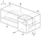
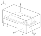
次に図7、図8を用いて、シリンダヘッドカバー70の製造方法について説明する。シリンダヘッドカバー70の本体部71と、突出分岐路80A(または孔部80B)と、側方突出部72は、樹脂または金属の型成形品であって一体成形品とされている。
● [Manufacturing method of cylinder head cover 70 (FIGS. 7 and 8)]
Next, a method of manufacturing the
図7及び図8に示すように、本体部71と突出分岐路80Aは、少なくとも一方が本体型抜き方向DZ(図7参照、この場合、Z軸方向)に沿って移動可能な一方型KU(金型等)と他方型KL(金型等)の少なくとも一方にて形成される。突出分岐路80A(または孔部80B)は、一方型KUまたは他方型KLにて形成され、突出方向(または開口方向)が本体型抜き方向DZに沿うように形成される。例えば、本体型抜き方向DZを上方向に設定し、一方型KUを他方型KLの上方に配置した場合、突出分岐路80A(または孔部80B)は、一方型KUにて形成される。これにより、本体部71と突出分岐路80A(または孔部80B)を、容易に一体成形することができるとともに、本体部71を作る型である一方型KU及び他方型KLにて本体部71と突出分岐路80A(または孔部80B)を同時に成形することができる。従って、部品点数と製造工程を低減することができる。
As shown in FIGS. 7 and 8, at least one of the
また、図7及び図8に示すように、側方突出部72は、筒状の側方突出部72の軸線方向であって本体型抜き方向DZとは異なる方向である側方型抜き方向DX(図7、図8参照、この場合、X軸方向)に沿って移動可能な側方型KS(金型等)にて無理抜き製法で形成される。なお、側方突出部72は、本体部71と一体成形される。従って、本体部71と突出分岐路80A(または孔部80B)と側方突出部72は、一体成形される。これにより、本体部71及び側方突出部72を一体成形した後、突出分岐路80A(または孔部80B)を、後工程で溶接等する(孔部の場合は孔あけする)必要が無く、部品点数と製造工程を低減することができる。
Further, as shown in FIGS. 7 and 8, the
本発明のシリンダヘッドカバー70、シリンダヘッドカバーの製造方法は、本実施の形態で説明した構成、構造、製造方法等に限定されず、本発明の要旨を変更しない範囲で種々の変更、追加、削除が可能である。例えばターボ過給機30が省略されていてもよい。
The method for manufacturing the
また、本発明のシリンダヘッドカバー及びシリンダヘッドカバーの製造方法は、ディーゼルエンジンに限定されず、ガソリンエンジン等、種々の内燃機関に適用することが可能である。 Further, the method for manufacturing a cylinder head cover and a cylinder head cover of the present invention is not limited to a diesel engine, and can be applied to various internal combustion engines such as a gasoline engine.
また本実施の形態の説明では、シリンダヘッドとは反対の側に孔部80Bを開口した例を説明したが(図5参照)、孔部80Bの開口方向を側方突出部72の延びる方向と同じ方向にしてもよい。同様に、本実施の形態の説明では、シリンダヘッドとは反対の側に突出分岐路80Aを配置した例を説明したが(図4参照)、突出分岐路80Aの突出方向を側方突出部72の延びる方向と同じ方向にしてもよい。
Further, in the description of the present embodiment, an example in which the
また本実施の形態の説明では、経路断面積最小部70A及び突出分岐路80A(または孔部80B)を接続経路部74に設けた例を説明したが(図4、図5参照)、経路断面積最小部70A及び突出分岐路80A(または孔部80B)をラビリンス経路部73に設けてもよい。
Further, in the description of the present embodiment, an example in which the path cross-sectional area
また本実施の形態の説明では、シリンダヘッドカバー高さが、周囲のシリンダヘッドカバー高さよりも低くなっているシリンダヘッドカバーの個所に経路断面積最小部を設けた例を説明したが(図4、図5参照)、周囲のシリンダヘッドカバー高さと同等以上の高さのシリンダヘッドカバーの個所に経路断面積最小部を設けるようにしてもよい。 Further, in the description of the present embodiment, an example in which the minimum path cross-sectional area is provided at the position of the cylinder head cover where the cylinder head cover height is lower than the surrounding cylinder head cover height has been described (FIGS. 4 and 5). (See), the minimum path cross-sectional area may be provided at a position of the cylinder head cover having a height equal to or higher than the height of the surrounding cylinder head cover.
また本実施の形態の説明では、本体型抜き方向DZを上方向に設定し、一方型KUを他方型KLの上方に配置した例を説明したが、本体型抜き方向DZを略水平方向に設定し、一方型KUを他方型KLの側方に配置するようにしてもよい。 Further, in the description of the present embodiment, an example in which the main body die cutting direction DZ is set upward and the one-sided KU is arranged above the other-type KL has been described, but the main body die-cutting direction DZ is set substantially horizontally. However, the one-sided KU may be arranged on the side of the other-type KL.
10 内燃機関
11A、11B 吸気管
11C 吸気マニホルド
12A 排気マニホルド
12B、12C 排気管
13 EGR配管
14 EGR弁
15 EGRクーラ
21 吸気流量検出手段
22 回転検出手段
23 大気圧検出手段
24A コンプレッサ上流圧力検出手段
24B コンプレッサ下流圧力検出手段
24C 圧力検出手段
25 アクセルペダル踏込量検出手段
26A タービン上流圧力検出手段
26B タービン下流圧力検出手段
27 車速検出手段
28A、28B 吸気温度検出手段
28C クーラント温度検出手段
29 排気温度検出手段
30 ターボ過給機
31 ノズル駆動手段
32 ノズル開度検出手段
33 可変ノズル
35 コンプレッサ
35A コンプレッサインペラ
36 タービン
36A タービンインペラ
41 コモンレール
43A~43D インジェクタ
45A~45D シリンダ
47 スロットル装置
47S スロットル開度検出手段
50 制御装置
51 制御手段
53 記憶手段
61 排気浄化装置
70 シリンダヘッドカバー
70A 経路断面積最小部
71 本体部
72 側方突出部
73 ラビリンス経路部
74 接続経路部
75 本体部内ガス経路
80A 突出分岐路
80B 孔部
81 圧力検出手段
82 (ブローバイガス還流用)配管
DX 側方型抜き方向
DZ 本体型抜き方向
KU 一方型
KL 他方型
KS 側方型
10
Claims (6)
前記シリンダヘッドカバーは、樹脂または金属の型成形品であって前記内燃機関のシリンダヘッドを覆うように設けられてブローバイガスが集められる本体部と、前記本体部の側方に突出するように設けられてブローバイガスを前記吸気経路に向けて吐出する側方突出部と、を有しており、
前記側方突出部と前記吸気経路とは配管にて接続され、
前記本体部は、集められたブローバイガスを前記側方突出部まで導くとともに所定の経路断面積を有する本体部内ガス経路を有しており、
前記本体部内ガス経路から前記側方突出部の出口までのブローバイガスが流れる経路であるカバー内ガス経路において、経路の断面積が最小となる経路断面積最小部は、前記側方突出部ではなく前記本体部内ガス経路に設けられており、
前記本体部における前記経路断面積最小部の位置よりも下流側となる前記本体部内ガス経路の位置に、前記本体部内ガス経路内の圧力を検出する圧力検出手段を前記本体部の外側から取り付けるための孔部、または前記圧力検出手段を前記本体部の外側から接続するための突出分岐路、が形成されており、
前記本体部と、前記側方突出部と、前記孔部または前記突出分岐路は、一体成形品とされている、
シリンダヘッドカバー。 A cylinder head cover in a blow-by gas recirculation system that allows blow-by gas generated in an internal combustion engine to flow from the internal combustion engine to an intake path.
The cylinder head cover is a molded product of resin or metal and is provided so as to cover the cylinder head of the internal combustion engine and is provided so as to project to the side of the main body portion and a main body portion from which blow-by gas is collected. It has a lateral protrusion that discharges blow-by gas toward the intake path.
The lateral protrusion and the intake path are connected by a pipe.
The main body has a gas path in the main body that guides the collected blow-by gas to the lateral protrusion and has a predetermined path cross-sectional area.
In the in-cover gas path, which is the path through which blow-by gas flows from the gas path in the main body to the outlet of the lateral protrusion, the path cross-sectional area minimum portion that minimizes the cross-sectional area of the path is not the lateral protrusion. It is provided in the gas path in the main body, and is provided.
To attach a pressure detecting means for detecting the pressure in the gas path in the main body from the outside of the main body to the position of the gas path in the main body downstream from the position of the minimum cross-sectional area of the path in the main body. A protruding branch path for connecting the hole portion or the pressure detecting means from the outside of the main body portion is formed.
The main body portion, the lateral protrusion portion, the hole portion, or the protrusion branch path is an integrally molded product.
Cylinder head cover.
前記孔部が形成されている場合、前記内燃機関に前記シリンダヘッドカバーを取り付けた際に前記孔部は、前記シリンダヘッドとは反対の側に配置されて、前記シリンダヘッドとは反対の側に開口するように形成されており、
前記突出分岐路が形成されている場合、前記内燃機関に前記シリンダヘッドカバーを取り付けた際に前記突出分岐路は、前記シリンダヘッドとは反対の側に配置されて、前記シリンダヘッドとは反対の側に突出するように形成されている、
シリンダヘッドカバー。 The cylinder head cover according to claim 1.
When the hole is formed, when the cylinder head cover is attached to the internal combustion engine, the hole is arranged on the side opposite to the cylinder head and opens on the side opposite to the cylinder head. Formed to do,
When the protruding branch path is formed, the protruding branch path is arranged on the side opposite to the cylinder head when the cylinder head cover is attached to the internal combustion engine, and the side opposite to the cylinder head. Formed to protrude into,
Cylinder head cover.
前記本体部内ガス経路は、迷路状に経路が形成されたラビリンス経路部と、前記ラビリンス経路部の終端から前記側方突出部までを接続する接続経路部と、を有しており、
前記経路断面積最小部と、前記孔部または前記突出分岐路と、が前記接続経路部に設けられている、
シリンダヘッドカバー。 The cylinder head cover according to claim 1 or 2.
The gas path in the main body includes a labyrinth path portion in which a path is formed in a maze shape, and a connection path portion connecting from the end of the labyrinth path portion to the lateral protrusion.
The path cross-sectional area minimum portion and the hole portion or the protruding branch path are provided in the connection path portion.
Cylinder head cover.
前記内燃機関に前記シリンダヘッドカバーを取り付けた際の前記シリンダヘッドカバーにおける前記シリンダヘッドの側から前記シリンダヘッドとは反対の側に向かう方向の高さをシリンダヘッドカバー高さとした場合、
前記経路断面積最小部は、前記シリンダヘッドカバー高さが周囲の前記シリンダヘッドカバー高さよりも低くなっている前記シリンダヘッドカバーの個所に設けられている、
シリンダヘッドカバー。 The cylinder head cover according to any one of claims 1 to 3.
When the height of the cylinder head cover when the cylinder head cover is attached to the internal combustion engine in the direction from the side of the cylinder head to the side opposite to the cylinder head is defined as the cylinder head cover height.
The path cross-sectional area minimum portion is provided at a position of the cylinder head cover where the height of the cylinder head cover is lower than the height of the surrounding cylinder head cover.
Cylinder head cover.
前記シリンダヘッドカバーは、樹脂または金属の型成形品であり、前記内燃機関のシリンダヘッドを覆うように設けられてブローバイガスが集められる本体部と、前記本体部の側方に突出するように設けられてブローバイガスを前記吸気経路に向けて吐出する側方突出部と、を有し、
前記本体部に、集められたブローバイガスを前記側方突出部まで導くとともに所定の経路断面積を有する本体部内ガス経路を設定し、
前記本体部内ガス経路から前記側方突出部の出口までのブローバイガスが流れる経路であるカバー内ガス経路において、経路の断面積が最小となる経路断面積最小部を、前記側方突出部ではなく前記本体部内ガス経路に設定し、
前記本体部における前記経路断面積最小部の位置よりも下流側となる前記本体部内ガス経路の位置に、前記本体部内ガス経路内の圧力を検出する圧力検出手段を前記本体部の外側から取り付けるための孔部、または前記圧力検出手段を前記本体部の外側から接続するための突出分岐路、を設定し、
前記本体部と、前記孔部または突出分岐路とを、少なくとも一方が本体型抜き方向に沿って移動可能な一方型と他方型の少なくとも一方にて形成し、
前記側方突出部を、前記側方突出部の軸線方向であって前記本体型抜き方向とは異なる方向である側方型抜き方向に移動可能な側方型にて形成することで、前記本体部と、前記孔部または前記突出分岐路と、前記側方突出部と、を一体成形する、
シリンダヘッドカバーの製造方法。 A method for manufacturing a cylinder head cover in a blow-by gas recirculation system in which blow-by gas generated in an internal combustion engine is flowed from the internal combustion engine to an intake path.
The cylinder head cover is a molded product made of resin or metal, and is provided so as to cover the cylinder head of the internal combustion engine and to project from the main body portion where blow-by gas is collected and to the side of the main body portion. With a lateral protrusion that discharges blow-by gas toward the intake path.
A gas path in the main body having a predetermined path cross-sectional area is set in the main body while guiding the collected blow-by gas to the lateral protrusion.
In the in-cover gas path, which is the path through which blow-by gas flows from the gas path in the main body to the outlet of the lateral protrusion, the path cross-sectional area minimum portion that minimizes the cross-sectional area of the path is not the lateral protrusion. Set in the gas path inside the main body,
To attach a pressure detecting means for detecting the pressure in the gas path in the main body from the outside of the main body to the position of the gas path in the main body downstream from the position of the minimum cross-sectional area of the path in the main body. A protruding branch path for connecting the hole portion or the pressure detecting means from the outside of the main body portion is set.
The main body portion and the hole portion or the protruding branch path are formed by at least one of one mold and the other mold in which at least one of them can move along the main body die cutting direction.
The main body is formed by forming the lateral protrusion in a lateral mold that is movable in a side die cutting direction that is in the axial direction of the side protrusion and is different from the main body die cutting direction. The portion, the hole portion or the projecting branch path, and the lateral projecting portion are integrally molded.
Manufacturing method of cylinder head cover.
前記本体型抜き方向を上方向に設定し、
前記一方型を前記他方型の上方に配置し、
前記孔部または前記突出分岐路を、前記一方型にて形成する、
シリンダヘッドカバーの製造方法。
The method for manufacturing a cylinder head cover according to claim 5.
Set the main body die cutting direction to the upward direction,
The one mold is placed above the other mold and
The hole or the protruding branch path is formed by the one-sided mold.
Manufacturing method of cylinder head cover.
Priority Applications (3)
| Application Number | Priority Date | Filing Date | Title |
|---|---|---|---|
| JP2018176978A JP6996463B2 (en) | 2018-09-21 | 2018-09-21 | Manufacturing method of cylinder head cover and cylinder head cover |
| US16/565,795 US10927731B2 (en) | 2018-09-21 | 2019-09-10 | Cylinder head cover and method of manufacturing the cylinder head cover |
| BR102019019499-5A BR102019019499A2 (en) | 2018-09-21 | 2019-09-19 | CYLINDER HEAD COVER AND MANUFACTURING METHOD CYLINDER HEAD COVER |
Applications Claiming Priority (1)
| Application Number | Priority Date | Filing Date | Title |
|---|---|---|---|
| JP2018176978A JP6996463B2 (en) | 2018-09-21 | 2018-09-21 | Manufacturing method of cylinder head cover and cylinder head cover |
Publications (2)
| Publication Number | Publication Date |
|---|---|
| JP2020045881A JP2020045881A (en) | 2020-03-26 |
| JP6996463B2 true JP6996463B2 (en) | 2022-01-17 |
Family
ID=69884015
Family Applications (1)
| Application Number | Title | Priority Date | Filing Date |
|---|---|---|---|
| JP2018176978A Active JP6996463B2 (en) | 2018-09-21 | 2018-09-21 | Manufacturing method of cylinder head cover and cylinder head cover |
Country Status (3)
| Country | Link |
|---|---|
| US (1) | US10927731B2 (en) |
| JP (1) | JP6996463B2 (en) |
| BR (1) | BR102019019499A2 (en) |
Families Citing this family (1)
| Publication number | Priority date | Publication date | Assignee | Title |
|---|---|---|---|---|
| JP7559787B2 (en) * | 2022-03-03 | 2024-10-02 | トヨタ自動車株式会社 | Internal combustion engine |
Citations (3)
| Publication number | Priority date | Publication date | Assignee | Title |
|---|---|---|---|---|
| CN202520396U (en) | 2012-03-27 | 2012-11-07 | 重庆长安汽车股份有限公司 | Ventilation pipe of engine cylinder head cover |
| JP2015048752A (en) | 2013-08-30 | 2015-03-16 | アイシン精機株式会社 | Sensor support structure |
| JP2015113763A (en) | 2013-12-11 | 2015-06-22 | 愛知機械工業株式会社 | Cam angle sensor fixture and internal combustion engine |
Family Cites Families (12)
| Publication number | Priority date | Publication date | Assignee | Title |
|---|---|---|---|---|
| JPS62145916U (en) * | 1986-03-07 | 1987-09-14 | ||
| JPH03172524A (en) * | 1989-11-30 | 1991-07-25 | Toyota Autom Loom Works Ltd | Mechanism for preventing engine trouble by sensing abnormal pressure in pcv room |
| US6098603A (en) * | 1996-12-24 | 2000-08-08 | Denso Corporation | Blow-by gas passage abnormality detecting system for internal combustion engines |
| US20020184042A1 (en) * | 2001-06-01 | 2002-12-05 | Freemarkets, Inc. | Method, apparatus, and system for grouping transportation services |
| JP4960763B2 (en) * | 2007-05-16 | 2012-06-27 | 本田技研工業株式会社 | Internal combustion engine head cover |
| DE102013208231A1 (en) * | 2013-05-06 | 2014-11-06 | Mahle International Gmbh | Cylinder head cover |
| JP6146202B2 (en) * | 2013-08-22 | 2017-06-14 | トヨタ紡織株式会社 | Oil mist separator |
| JP6399427B2 (en) | 2013-12-25 | 2018-10-03 | ボルボトラックコーポレーション | Blowby gas recirculation system |
| JP2015140679A (en) * | 2014-01-27 | 2015-08-03 | アイシン精機株式会社 | Oil separator |
| JP2017219014A (en) * | 2016-06-10 | 2017-12-14 | ヤマハ発動機株式会社 | Gas-liquid separation device for blow-by gas of engine |
| JP6528810B2 (en) * | 2017-07-14 | 2019-06-12 | マツダ株式会社 | Engine cylinder head cover structure |
| JP2019132232A (en) * | 2018-02-01 | 2019-08-08 | トヨタ自動車株式会社 | Blow-by gas treatment device of internal combustion engine |
-
2018
- 2018-09-21 JP JP2018176978A patent/JP6996463B2/en active Active
-
2019
- 2019-09-10 US US16/565,795 patent/US10927731B2/en not_active Expired - Fee Related
- 2019-09-19 BR BR102019019499-5A patent/BR102019019499A2/en active Search and Examination
Patent Citations (3)
| Publication number | Priority date | Publication date | Assignee | Title |
|---|---|---|---|---|
| CN202520396U (en) | 2012-03-27 | 2012-11-07 | 重庆长安汽车股份有限公司 | Ventilation pipe of engine cylinder head cover |
| JP2015048752A (en) | 2013-08-30 | 2015-03-16 | アイシン精機株式会社 | Sensor support structure |
| JP2015113763A (en) | 2013-12-11 | 2015-06-22 | 愛知機械工業株式会社 | Cam angle sensor fixture and internal combustion engine |
Also Published As
| Publication number | Publication date |
|---|---|
| US20200095911A1 (en) | 2020-03-26 |
| US10927731B2 (en) | 2021-02-23 |
| BR102019019499A2 (en) | 2020-03-31 |
| JP2020045881A (en) | 2020-03-26 |
Similar Documents
| Publication | Publication Date | Title |
|---|---|---|
| JP4215069B2 (en) | Exhaust gas recirculation device for internal combustion engine | |
| JP5527486B2 (en) | Ventilation control device for internal combustion engine | |
| EP3290667B1 (en) | Blowby gas treatment device for internal combustion engine with supercharger | |
| JP2008150955A (en) | Exhaust gas recirculation device | |
| JP2006336547A (en) | EGR device | |
| JP6996463B2 (en) | Manufacturing method of cylinder head cover and cylinder head cover | |
| JP2009185751A (en) | Control device for internal combustion engine | |
| US10697358B2 (en) | Intake passage structure for turbocharger-equipped engine | |
| CN106481427B (en) | The exhaust apparatus of engine | |
| JP2013096229A (en) | Blowby gas recirculation device | |
| US8479510B2 (en) | Exhaust gas recirculation system | |
| JP4793245B2 (en) | Exhaust gas recirculation device for internal combustion engine | |
| JP2009108701A (en) | Exhaust gas recirculation device for internal combustion engine | |
| JP2006009745A (en) | Airflow sensor output correction method for internal combustion engine | |
| US10408120B2 (en) | Opening/closing valve structure | |
| US11643945B2 (en) | Internal combustion engine diagnosing device | |
| JPWO2018069975A1 (en) | Intake passage structure of a turbocharged engine | |
| JP2013221488A (en) | Control device for internal combustion engine with supercharger | |
| JP2009209816A (en) | Control device of internal combustion engine | |
| JPH10103168A (en) | Exhaust gas recirculation system for internal combustion engines | |
| JP2008208721A (en) | Exhaust gas recirculation device for internal combustion engine | |
| JP6328519B2 (en) | Exhaust gas recirculation device for engine with blow-by gas reduction device and supercharger | |
| JP4798497B2 (en) | Sensor cleaning device for internal combustion engine | |
| JP5577836B2 (en) | Blow-by gas processing device for internal combustion engine | |
| JP2012246891A (en) | Intake device of internal combustion engine with supercharger |
Legal Events
| Date | Code | Title | Description |
|---|---|---|---|
| A621 | Written request for application examination |
Free format text: JAPANESE INTERMEDIATE CODE: A621 Effective date: 20201218 |
|
| TRDD | Decision of grant or rejection written | ||
| A977 | Report on retrieval |
Free format text: JAPANESE INTERMEDIATE CODE: A971007 Effective date: 20211110 |
|
| A01 | Written decision to grant a patent or to grant a registration (utility model) |
Free format text: JAPANESE INTERMEDIATE CODE: A01 Effective date: 20211116 |
|
| A61 | First payment of annual fees (during grant procedure) |
Free format text: JAPANESE INTERMEDIATE CODE: A61 Effective date: 20211129 |
|
| R151 | Written notification of patent or utility model registration |
Ref document number: 6996463 Country of ref document: JP Free format text: JAPANESE INTERMEDIATE CODE: R151 |