WO2015098505A1 - 無灰炭の製造方法 - Google Patents
無灰炭の製造方法 Download PDFInfo
- Publication number
- WO2015098505A1 WO2015098505A1 PCT/JP2014/082579 JP2014082579W WO2015098505A1 WO 2015098505 A1 WO2015098505 A1 WO 2015098505A1 JP 2014082579 W JP2014082579 W JP 2014082579W WO 2015098505 A1 WO2015098505 A1 WO 2015098505A1
- Authority
- WO
- WIPO (PCT)
- Prior art keywords
- solvent
- coal
- slurry
- preparation
- temperature
- Prior art date
- Legal status (The legal status is an assumption and is not a legal conclusion. Google has not performed a legal analysis and makes no representation as to the accuracy of the status listed.)
- Ceased
Links
Images

Classifications
-
- C—CHEMISTRY; METALLURGY
- C10—PETROLEUM, GAS OR COKE INDUSTRIES; TECHNICAL GASES CONTAINING CARBON MONOXIDE; FUELS; LUBRICANTS; PEAT
- C10L—FUELS NOT OTHERWISE PROVIDED FOR; NATURAL GAS; SYNTHETIC NATURAL GAS OBTAINED BY PROCESSES NOT COVERED BY SUBCLASSES C10G OR C10K; LIQUIFIED PETROLEUM GAS; USE OF ADDITIVES TO FUELS OR FIRES; FIRE-LIGHTERS
- C10L5/00—Solid fuels
- C10L5/02—Solid fuels such as briquettes consisting mainly of carbonaceous materials of mineral or non-mineral origin
- C10L5/04—Raw material of mineral origin to be used; Pretreatment thereof
-
- C—CHEMISTRY; METALLURGY
- C10—PETROLEUM, GAS OR COKE INDUSTRIES; TECHNICAL GASES CONTAINING CARBON MONOXIDE; FUELS; LUBRICANTS; PEAT
- C10L—FUELS NOT OTHERWISE PROVIDED FOR; NATURAL GAS; SYNTHETIC NATURAL GAS OBTAINED BY PROCESSES NOT COVERED BY SUBCLASSES C10G OR C10K; LIQUIFIED PETROLEUM GAS; USE OF ADDITIVES TO FUELS OR FIRES; FIRE-LIGHTERS
- C10L9/00—Treating solid fuels to improve their combustion
-
- C—CHEMISTRY; METALLURGY
- C10—PETROLEUM, GAS OR COKE INDUSTRIES; TECHNICAL GASES CONTAINING CARBON MONOXIDE; FUELS; LUBRICANTS; PEAT
- C10L—FUELS NOT OTHERWISE PROVIDED FOR; NATURAL GAS; SYNTHETIC NATURAL GAS OBTAINED BY PROCESSES NOT COVERED BY SUBCLASSES C10G OR C10K; LIQUIFIED PETROLEUM GAS; USE OF ADDITIVES TO FUELS OR FIRES; FIRE-LIGHTERS
- C10L2230/00—Function and purpose of a components of a fuel or the composition as a whole
- C10L2230/22—Function and purpose of a components of a fuel or the composition as a whole for improving fuel economy or fuel efficiency
-
- C—CHEMISTRY; METALLURGY
- C10—PETROLEUM, GAS OR COKE INDUSTRIES; TECHNICAL GASES CONTAINING CARBON MONOXIDE; FUELS; LUBRICANTS; PEAT
- C10L—FUELS NOT OTHERWISE PROVIDED FOR; NATURAL GAS; SYNTHETIC NATURAL GAS OBTAINED BY PROCESSES NOT COVERED BY SUBCLASSES C10G OR C10K; LIQUIFIED PETROLEUM GAS; USE OF ADDITIVES TO FUELS OR FIRES; FIRE-LIGHTERS
- C10L2290/00—Fuel preparation or upgrading, processes or apparatus therefore, comprising specific process steps or apparatus units
- C10L2290/06—Heat exchange, direct or indirect
-
- C—CHEMISTRY; METALLURGY
- C10—PETROLEUM, GAS OR COKE INDUSTRIES; TECHNICAL GASES CONTAINING CARBON MONOXIDE; FUELS; LUBRICANTS; PEAT
- C10L—FUELS NOT OTHERWISE PROVIDED FOR; NATURAL GAS; SYNTHETIC NATURAL GAS OBTAINED BY PROCESSES NOT COVERED BY SUBCLASSES C10G OR C10K; LIQUIFIED PETROLEUM GAS; USE OF ADDITIVES TO FUELS OR FIRES; FIRE-LIGHTERS
- C10L2290/00—Fuel preparation or upgrading, processes or apparatus therefore, comprising specific process steps or apparatus units
- C10L2290/08—Drying or removing water
-
- C—CHEMISTRY; METALLURGY
- C10—PETROLEUM, GAS OR COKE INDUSTRIES; TECHNICAL GASES CONTAINING CARBON MONOXIDE; FUELS; LUBRICANTS; PEAT
- C10L—FUELS NOT OTHERWISE PROVIDED FOR; NATURAL GAS; SYNTHETIC NATURAL GAS OBTAINED BY PROCESSES NOT COVERED BY SUBCLASSES C10G OR C10K; LIQUIFIED PETROLEUM GAS; USE OF ADDITIVES TO FUELS OR FIRES; FIRE-LIGHTERS
- C10L2290/00—Fuel preparation or upgrading, processes or apparatus therefore, comprising specific process steps or apparatus units
- C10L2290/10—Recycling of a stream within the process or apparatus to reuse elsewhere therein
-
- C—CHEMISTRY; METALLURGY
- C10—PETROLEUM, GAS OR COKE INDUSTRIES; TECHNICAL GASES CONTAINING CARBON MONOXIDE; FUELS; LUBRICANTS; PEAT
- C10L—FUELS NOT OTHERWISE PROVIDED FOR; NATURAL GAS; SYNTHETIC NATURAL GAS OBTAINED BY PROCESSES NOT COVERED BY SUBCLASSES C10G OR C10K; LIQUIFIED PETROLEUM GAS; USE OF ADDITIVES TO FUELS OR FIRES; FIRE-LIGHTERS
- C10L2290/00—Fuel preparation or upgrading, processes or apparatus therefore, comprising specific process steps or apparatus units
- C10L2290/22—Impregnation or immersion of a fuel component or a fuel as a whole
-
- C—CHEMISTRY; METALLURGY
- C10—PETROLEUM, GAS OR COKE INDUSTRIES; TECHNICAL GASES CONTAINING CARBON MONOXIDE; FUELS; LUBRICANTS; PEAT
- C10L—FUELS NOT OTHERWISE PROVIDED FOR; NATURAL GAS; SYNTHETIC NATURAL GAS OBTAINED BY PROCESSES NOT COVERED BY SUBCLASSES C10G OR C10K; LIQUIFIED PETROLEUM GAS; USE OF ADDITIVES TO FUELS OR FIRES; FIRE-LIGHTERS
- C10L2290/00—Fuel preparation or upgrading, processes or apparatus therefore, comprising specific process steps or apparatus units
- C10L2290/24—Mixing, stirring of fuel components
-
- C—CHEMISTRY; METALLURGY
- C10—PETROLEUM, GAS OR COKE INDUSTRIES; TECHNICAL GASES CONTAINING CARBON MONOXIDE; FUELS; LUBRICANTS; PEAT
- C10L—FUELS NOT OTHERWISE PROVIDED FOR; NATURAL GAS; SYNTHETIC NATURAL GAS OBTAINED BY PROCESSES NOT COVERED BY SUBCLASSES C10G OR C10K; LIQUIFIED PETROLEUM GAS; USE OF ADDITIVES TO FUELS OR FIRES; FIRE-LIGHTERS
- C10L2290/00—Fuel preparation or upgrading, processes or apparatus therefore, comprising specific process steps or apparatus units
- C10L2290/54—Specific separation steps for separating fractions, components or impurities during preparation or upgrading of a fuel
-
- C—CHEMISTRY; METALLURGY
- C10—PETROLEUM, GAS OR COKE INDUSTRIES; TECHNICAL GASES CONTAINING CARBON MONOXIDE; FUELS; LUBRICANTS; PEAT
- C10L—FUELS NOT OTHERWISE PROVIDED FOR; NATURAL GAS; SYNTHETIC NATURAL GAS OBTAINED BY PROCESSES NOT COVERED BY SUBCLASSES C10G OR C10K; LIQUIFIED PETROLEUM GAS; USE OF ADDITIVES TO FUELS OR FIRES; FIRE-LIGHTERS
- C10L2290/00—Fuel preparation or upgrading, processes or apparatus therefore, comprising specific process steps or apparatus units
- C10L2290/54—Specific separation steps for separating fractions, components or impurities during preparation or upgrading of a fuel
- C10L2290/544—Extraction for separating fractions, components or impurities during preparation or upgrading of a fuel
Definitions
- the present invention relates to a method for producing ashless coal.
- Patent Document 1 there is a method for producing ashless coal (for example, Patent Document 1).
- the method for producing ashless coal described in Patent Document 1 is as follows (see claim 1 of the same document).
- Slurry preparation step for preparing a slurry by mixing a solvent and coal an extraction step for extracting a coal component soluble in a solvent by heating the slurry obtained in the slurry preparation step, and the extraction
- a method of circulating the recovered solvent to the slurry preparation step is a method for circulating the recovered solvent to the slurry preparation step.
- the method for producing ashless coal described in Patent Document 1 includes the step of obtaining ashless coal by recovering a solvent from a slurry containing a coal component insoluble in the solvent separated in the separation step. Yes (this process is called “ashless coal acquisition process”).
- the solvent recovered in the ashless charcoal acquisition step is at a high temperature (for example, 270 ° C.).
- the method for producing ashless coal described in Patent Document 1 includes “an extraction step in which the slurry obtained in the slurry preparation step is heated to extract a coal component soluble in a solvent”. The slurry supplied to the extraction process is heated (preheated) before the extraction process.
- the thermal energy of the solvent (high temperature side fluid) recovered in the ashless coal acquisition process as a heating source for the slurry (low temperature side fluid) supplied to the extraction process.
- the heating of the low temperature side fluid by the high temperature side fluid may be performed in a heat exchanger.
- the present invention provides a method for producing ashless coal that can effectively use the heat energy generated in the production process of ashless coal by efficiently performing heat exchange between coal and solvent and heat exchange between slurry and solvent.
- the purpose is to provide.
- the method for producing ashless coal of the present invention comprises a slurry preparation step of mixing coal and a solvent to prepare a slurry, dehydrating coal contained in the slurry, and raising the temperature of the slurry, and the slurry preparation step An extraction step for extracting the coal component soluble in the solvent by heating the slurry obtained in the above, a solution containing the coal component soluble in the solvent, and a coal insoluble in the solvent, the slurry obtained in the extraction step
- the separation process of separating into a solid concentrate in which the components are concentrated the ashless coal acquisition process for obtaining ashless coal by evaporating and separating the solvent from the solution separated in the separation process, and the ashless coal acquisition process
- a solvent liquid circulated in the circulation step and coal are mixed to prepare a slurry and dehydrate the coal, and a solvent vapor circulated in the circulation step.
- heat energy generated in the process of producing ashless coal can be effectively used by efficiently performing heat exchange between coal and solvent and heat exchange between slurry and solvent.
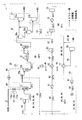
- FIG. 1 is a schematic view of an ashless coal production apparatus 1. It is the schematic of the ashless coal manufacturing apparatus 101 of a comparative example.
- the ashless coal manufacturing apparatus 1 in which the manufacturing method of ashless coal and the manufacturing method of ashless coal are performed is demonstrated.
- the ashless coal production apparatus 1 is an apparatus for producing ashless coal (HPC: Hyper-coal) by removing ash from raw material coal (also simply referred to as “coal”).
- the ashless coal production apparatus 1 includes coal / slurry processing devices 11 to 37, circulation paths 41 to 46, and circulation path devices 51 to 91.
- the coal / slurry processing devices 11 to 37 are devices for processing coal and slurry (described later).
- the coal / slurry processing apparatuses 11 to 37 include a coal supply line 11 and a steam discharge device 13. Further, the coal / slurry processing devices 11 to 37 are, in order from the upstream side of the ashless coal production process, the slurry preparation device 20, the preheater 31, the extraction tank 33, the separation device 35, the solvent recovery device 37, and the like. .
- the coal supply line 11 supplies coal to the slurry preparation device 20 (coal supply process).
- the coal supply line 11 supplies coal from a feeder or the like (not shown) to a preparation dewatering tank 21 (described later) of the slurry preparation device 20.
- This coal is, for example, bituminous coal or low-grade coal (brown coal, subbituminous coal).
- Bituminous coal has a higher extraction rate (ratio of soluble components of coal extracted into solvent) than low-grade coal.
- Low-grade coal is less expensive than bituminous coal.
- the steam discharge device 13 discharges steam generated in the preparation dehydration tank 21 (described later) from the coal supply line 11 by flowing purge gas into the coal supply line 11 (steam discharge step).
- the purge gas is a gas in a gas state in the coal supply line 11, and is, for example, nitrogen (purge nitrogen).
- the steam discharge device 13 is provided to suppress the problem of blockage of the coal supply line 11.
- the “occlusion problem” may occur as follows. Steam is generated as a result of heating and dewatering of coal in the preparation dewatering tank 21 (described later). Most of the vapor is water vapor, and a part of the vapor is solvent vapor (a gaseous solvent).
- the steam discharge device 13 includes a valve 13a and a purge gas supply device 13b.
- the valve 13a is disposed on the coal supply line 11. By opening and closing the valve 13a, the flow of substances (coal, steam, and purge gas) passing through the coal supply line 11 is controlled. It is preferable that a plurality of (for example, two) valves 13 a are arranged in series on the coal supply line 11. When a plurality of valves 13 a are arranged on the coal supply line 11, it is possible to further suppress the entry of steam into the coal supply line 11 compared to the case where only one valve 13 a is arranged.
- the valve 13a is a rotary valve, for example.
- the purge gas supply device 13b supplies purge gas into the coal supply line 11 (purge gas supply process).
- the purge gas supply device 13b supplies purge gas between the two valves 13a.
- the slurry preparation device 20 mixes coal and a solvent to prepare a slurry (coal-solvent slurry), and dehydrates and raises the temperature of the slurry (slurry preparation step).
- the solvent supplied to the slurry preparation device 20 dissolves coal. It is preferable that this solvent has a high ratio (extraction rate) of soluble components of coal extracted in the extraction tank 33. From the viewpoint of extraction rate, this solvent is preferably stable even in a heated state, and preferably has a large dissolving power for coal (excellent affinity with coal). This solvent preferably has a high solvent recovery rate in the solvent recovery device 37. From the viewpoint of the solvent recovery rate, it is preferable that this solvent can be easily recovered by a method such as distillation. The boiling point of the solvent is preferably, for example, 180 to 300 ° C., more preferably 230 to 280 ° C.
- This solvent is, for example, a coal derivative.
- This solvent is mainly refined from the dry distillation product of coal.
- This solvent is, for example, a solvent containing an aromatic compound (aromatic solvent).
- the main component of this solvent is a bicyclic aromatic. Examples of the bicyclic aromatic are naphthalene, methylnaphthalene, dimethylnaphthalene, trimethylnaphthalene, and the like.
- the solvent is naphthalenes, anthracenes, fluorenes each having an aliphatic side chain, or alkylbenzene having biphenyl or a long aliphatic side chain added thereto.
- the solvent is methyl naphthalene oil or naphthalene oil.
- Methyl naphthalene oil and naphthalene oil are distillate oils by-produced when coke is produced by dry distillation of coal.
- the slurry preparation device 20 includes a preparation dehydration tank 21 and a preparation temperature raising device 23.
- the preparation dehydration tank 21 performs slurry preparation and coal dehydration by mixing a solvent solution (a solvent in a liquid state) and coal (preparation dehydration step).
- the solvent liquid supplied to the preparation dehydration tank 21 is a solvent liquid circulated through a part of the circulation paths 41 to 46.
- Coal supplied to the preparation dehydration tank 21 is supplied from the coal supply line 11. Mixing of the solvent liquid and coal in the preparation dehydration tank 21 is performed, for example, by putting coal into the solvent liquid in the preparation dehydration tank 21.
- a slurry is prepared by mixing the solvent liquid and coal in the preparation dehydration tank 21.
- the S / C (Slurry / Coal; the ratio of the mass of the slurry to the mass of the dry coal) of the slurry prepared in the preparation dewatering tank 21 is, for example, about 2.0.
- This preparation dehydration tank 21 dehydrates coal as follows.
- the preparation dewatering tank 21 directly contacts the solvent liquid and the coal by mixing the solvent liquid and the coal.
- the preparation dehydration tank 21 causes heat exchange directly between the solvent liquid and the coal by this direct contact.
- the preparation dehydration tank 21 raises the temperature of coal by this heat exchange, and evaporates moisture (coal-containing water) in the coal.
- the temperature of the solvent liquid supplied to the preparation dehydration tank 21 is equal to or higher than the temperature necessary for this dehydration and is lower than the boiling point of the solvent.
- the temperature of the solvent liquid supplied to the preparation dehydration tank 21 is, for example, 230 ° C. or higher, preferably 235 ° C. or higher, for example, 240 ° C. or lower.
- the temperature of the solvent liquid supplied to the preparation dehydration tank 21 is 237 ° C. in the example shown in FIG. 1 (refer to FIG. 1 below for specific examples of temperature).
- the preparation temperature raising device 23 prepares the slurry and raises the temperature by mixing the solvent vapor and the slurry (preparation temperature raising step).
- the preparation heating device 23 adjusts the concentration of the slurry so that the inlet concentration of the extraction tank 33 is obtained.
- the inlet concentration of the extraction tank 33 is set in advance. There is no need to provide a device for adjusting the concentration of the slurry between the preparation heating device 23 and the extraction tank 33, and the ashless coal manufacturing apparatus 1 does not have such a device.
- the S / C of the slurry prepared by the preparation heating device 23 is, for example, about 4.0.
- the preparation temperature raising device 23 raises the temperature of the slurry to the inlet temperature of the device to which the slurry is supplied next to the slurry preparation device 20 (hereinafter referred to as “device after slurry preparation”).
- the inlet temperature of the “post-slurry equipment” is set in advance.
- the “post-slurry equipment” is specifically the preheater 31, and the extraction tank 33 when the preheater 31 is not provided. There is no need to provide a device for adjusting the temperature of the slurry between the preparation temperature raising device 23 and the “post-slurry device”, and the ashless coal production apparatus 1 does not have such a device.
- the preparation temperature raising device 23 includes a venturi scrubber 23a and a preparation temperature raising tank 23b.
- the venturi scrubber 23a mixes solvent vapor and slurry (first preparation heating step).
- the solvent vapor supplied to the venturi scrubber 23a is solvent vapor circulated by a part of the circulation paths 41 to 46 (details will be described later).
- the slurry supplied to the venturi scrubber 23 a is supplied from the preparation dehydration tank 21.
- the slurry supplied to the venturi scrubber 23a is a slurry after being prepared and dehydrated in the preparation dewatering tank 21.
- the venturi scrubber 23a directly mixes the slurry and the solvent vapor by mixing the slurry and the solvent vapor.
- the venturi scrubber 23a directly exchanges heat between the solvent vapor and the slurry by this direct contact.
- the venturi scrubber 23a uses the latent heat of the solvent vapor (using the heat generated when the solvent vapor condenses) to heat the slurry.
- the venturi scrubber 23a dehydrates the coal in the slurry by heating the slurry.
- the venturi scrubber 23a makes the slurry fine particles and mixes the fine particle slurry and solvent vapor.
- the venturi scrubber 23a increases the flow rates of the fine particle slurry and the solvent vapor, and generates a shearing force between the fine particle slurry and the solvent vapor, thereby mixing the fine particle slurry and the solvent vapor.
- an apparatus other than the venturi scrubber that mixes the solvent vapor and the slurry may be used.
- the “apparatus other than the venturi scrubber” include a static mixer. The static mixer stirs and mixes the particulate slurry and the solvent vapor by an element (a member formed by twisting a plate, a screw-like member) disposed inside the tube.
- Preparation warming tank 23b further mixes the mixture mixed with venturi scrubber 23a (second preparation warming step).
- the preparation temperature rising tank 23b further heat-exchanges a slurry and a solvent by this mixing.
- the inside of the preparation heating tank 23b is pressurized so as to suppress the vaporization (solvent vapor loss) of the solvent, and is pressurized to, for example, 50 kPaG.
- the preheater 31 preheats the slurry prepared by the preparation temperature raising device 23 (by the slurry preparation device 20) before being supplied to the extraction tank 33 (preheating step). Note that the preheater 31 may not be provided.
- the extraction tank 33 heats the slurry obtained by the slurry preparation device 20 to extract a coal component (solvent soluble component) soluble in the solvent (extraction process).
- the extraction tank 33 extracts organic components in the coal. Details of this extraction are as follows.
- the slurry supplied to the extraction tank 33 is heated and held at a predetermined temperature (described later) while being stirred by a stirrer provided in the extraction tank 33.
- a solvent soluble component is extracted from a slurry.
- the extract includes not only a solvent-soluble component but also a component insoluble in a solvent (a solvent-insoluble component) (for example, ash).
- the heating temperature of the slurry in the extraction tank 33 is a temperature at which the solvent-soluble component can be dissolved in the solvent.
- the heating temperature of the slurry is, for example, 300 ° C. or higher, preferably 360 ° C. or higher.
- the heating temperature of the slurry is, for example, 420 ° C. or less, preferably 400 ° C. or less.
- the heating temperature of the slurry is less than 300 ° C., it is insufficient to weaken the bond between coal molecules, so that the amount of the solvent-soluble component dissolved in the solvent becomes low.
- the heating temperature of the slurry exceeds 420 ° C., the pyrolysis reaction of coal becomes active, and recombination of the generated pyrolysis radicals occurs, so that the extraction rate of solvent-soluble components decreases.
- the extraction performed in the extraction tank 33 is preferably performed in the presence of an inert gas (for example, inexpensive nitrogen is preferable).
- an inert gas for example, inexpensive nitrogen is preferable.
- the pressure in the extraction tank 33 pressure applied to the solvent and slurry, operation pressure
- the pressure in the extraction tank 33 is preferably 1.0 to 2.0 MPa, although it depends on the temperature at the time of extraction and the vapor pressure of the solvent used.
- the separation device 35 is a slurry containing the coal component soluble in the solvent (solution part, supernatant liquid, overflow) and a solid content concentrate in which the coal component insoluble in the solvent is concentrated. Underflow) (separation process).
- the separation method include a gravity sedimentation method, a filtration method, and a centrifugal separation method.
- Gravity sedimentation is a method in which a slurry is held in a tank and a solvent-insoluble component is settled using gravity to separate the solution into a solid concentrate.
- the inside of the separation device 35 is kept warm (or heated) and pressurized.
- the temperature in the separation device 35 is, for example, 300 to 380 ° C.
- the pressure in the separation device 35 is, for example, 1.0 to 3.0 MPa.
- the separation device 35 is, for example, a two-stage type (the number of gravity settling tanks is 2).
- the two-stage separation device 35 includes a first gravity settling tank 35a and a second gravity settling tank 35b.
- the separation device 35 may be a one-stage type (the number of gravity settling tanks is 1).
- the separation device 35 completely separates the supernatant liquid and the solid concentrate, but solids (coal components insoluble in the solvent) are mixed in a part of the finished liquid, In some cases, the supernatant is mixed with a part of the solid concentrate.
- the solvent recovery device 37 recovers the solvent from the solution separated by the separation device 35.
- the solvent recovery device 37 is a device for obtaining ashless coal or by-product coal (described later) from the solution separated by the separation device 35.
- the solvent recovery device 37 includes a first solvent recovery device 37a and a second solvent recovery device 37b.
- the first solvent recovery device 37a is a device for obtaining ashless coal (HPC) by evaporating and separating the solvent from the solution separated by the separation device 35 (device for performing an ashless coal acquisition step).
- Ashless charcoal is charcoal that has no moisture and contains almost no ash. Ash content contained in ashless coal is 5% by weight or less, preferably 3% by weight or less. Ashless coal has a higher calorific value than coal as a raw material, and has good ignitability and burn-out properties. Therefore, ashless coal is used as a highly efficient fuel such as a boiler. Ashless coal has higher fluidity (softening and melting property) than raw coal, and is used, for example, as a raw material for iron-making coke or a part of raw material (blended coal).
- Examples of the method for evaporating and separating the solvent performed in the first solvent recovery device 37a include a distillation method and an evaporation method.
- Examples of the evaporation method include a spray drying method.
- Examples of the distillation method include a flash distillation method and a thin film distillation method.
- recovery apparatus 37a is a flash tank (flasher) for performing flash distillation method.
- recovery apparatus 37a is a thin film distillation tank for performing a thin film distillation method.
- recovery apparatus 37a is an apparatus provided with a flash tank and a thin film distillation tank (it arrange
- Flash method Evaporative separation of the solvent by the flash method is performed as follows.
- the pressure in the flash tank is set to a lower pressure (for example, 70 kPaG) than in the separation device 35.
- the solution separated by the separation device 35 is ejected into the flash tank.
- the solvent in the solution is evaporated and separated from the solution.
- recovery apparatus 37a may be equipped with a flash distillation tank and the thin film distillation tank of the downstream side of a flash distillation tank. In this case, the temperature of the solution decreases due to distillation in the flash tank. Therefore, in order to properly evaporate the solvent in the thin film distillation tank, the wall surface of the thin film distillation tank is heated.
- the second solvent recovery device 37b is a device (by-product coal) for obtaining by-product coal (RC; Residue coal) (also called residual coal) by evaporating and separating the solvent from the solid concentrate separated by the separation device 35.
- By-product charcoal is charcoal enriched with solvent-insoluble components (such as ash), and is used, for example, as part of a blended coal as a raw material for coke.
- a method for evaporating and separating the solvent in the second solvent recovery device 37b there are a distillation method, an evaporation method, and the like, similarly to the method for evaporating and separating the solvent in the first solvent recovery device 37a.
- recovery apparatus 37b does not need to be provided.
- Circulation paths 41 to 46 circulate the solvent evaporated and separated by the solvent recovery device 37 or the like (circulation process).
- the circulation paths 41 to 46 are flow paths (piping) for reusing the solvent.
- the circulation paths 41 to 46 include a first circulation path 41, a second circulation path 42, a third circulation path 43, a fourth circulation path 44, a fifth circulation path 45, and a sixth circulation path 46. Prepare.
- the first circulation path 41 circulates the solvent evaporated and separated by the first solvent recovery device 37a to the preparation dehydration tank 21 (first circulation step).
- the first circulation path 41 introduces the solvent taken out from the top of the first solvent recovery device 37 a into the preparation dehydration tank 21.
- the second circulation path 42 circulates the solvent evaporated and separated by the first solvent recovery device 37a to the preparation heating device 23 (second circulation step).
- the second circulation path 42 circulates the solvent evaporated and separated by the first solvent recovery device 37a to the venturi scrubber 23a.
- the second circulation path 42 circulates the solvent evaporated and separated by the first solvent recovery device 37a directly to the venturi scrubber 23a (without performing heat recovery or temperature increase).
- the sum of the pipe pressure loss (for example, 20 kPaG) in the second circulation path 42 and the operating pressure (for example, 50 kPaG) in the venturi scrubber 23a is equal to the operating pressure (for example, 70 kPaG) in the first solvent recovery device 37a. Therefore, the operating pressure in the first solvent recovery device 37a is set based on the sum of the operating pressure in the venturi scrubber 23a and the pipe pressure loss in the second circulation path 42.
- the third circulation path 43 circulates the solvent evaporated and separated by the first solvent recovery device 37a to the separation device 35 (third circulation step).
- the third circulation path 43 circulates the solvent evaporated and separated by the first solvent recovery device 37a to the second gravity settling tank 35b.
- Supply of the solvent (high-temperature solvent condensate) from the third circulation path 43 to the second gravity settling tank 35b provides the necessary amount of solvent supply to the second gravity settling tank 35b.
- the fourth circulation path 44 circulates the solvent evaporated and separated by the second solvent recovery device 37b to the preparation dehydration tank 21 (fourth circulation step).
- the fourth circulation path 44 introduces the solvent taken out from the top of the second solvent recovery device 37 b into the preparation dehydration tank 21.
- the steam introduced from the second solvent recovery device 37b into the fourth circulation path 44 includes not only the solvent but also nitrogen.
- the fifth circulation path 45 circulates the steam generated in the slurry preparation device 20 to the preparation dehydration tank 21 (fifth circulation step).
- the steam generated in the slurry preparation device 20 contains a solvent and water, and contains more water than the solvent.
- the fifth circulation path 45 circulates the steam generated in the preparation dehydration tank 21 to the preparation dehydration tank 21.
- the fifth circulation path 45 circulates the steam generated in the preparation heating tank 23 b to the preparation dehydration tank 21.
- the sixth circulation path 46 circulates the solvent vapor generated in the extraction tank 33 to the preparation dehydration tank 21 (sixth circulation step).
- Circulation path devices 51 to 91 are devices arranged on the circulation paths 41 to 46 (except on the second circulation path 42).
- the circulation path devices 51 to 91 include the following devices.
- a device disposed on the first circulation path 41 includes a recovered solvent tank 51.
- the devices arranged on the third circulation path 43 include an exhaust heat recovery boiler 61, a heat exchanger 63, and a preheater 65 in order from the upstream side.
- the devices arranged on the fourth circulation path 44 include, in order from the upstream side, a bag filter 71, an exhaust heat recovery boiler 73, a cooler 75, a heat exchanger 77, and a recovery solvent tank 51.
- the devices arranged on the fifth circulation path 45 include a cooler 81, an oil / water separation tank 83, a heat exchanger 77, and a recovery solvent tank 51 in this order from the upstream side.
- the equipment arranged on the sixth circulation path 46 includes, in order from the upstream side, an oil temperature riser 91, a heat exchanger 63, a heat exchanger 77, an oil / water separation tank 83, a heat exchanger 77, and a recovered solvent tank 51. There is.
- the recovery solvent tank 51 prepares a solvent liquid to be supplied to the preparation dehydration tank 21 (solvent liquid preparation step).
- the solvent supplied to the recovered solvent tank 51 is a solvent (solvent vapor) passing through the first circulation path 41, and more specifically, the solvent vapor evaporated and separated by the first solvent recovery device 37a.
- the solvent vapor evaporated and separated by the first solvent recovery device 37a is directly supplied to the recovery solvent tank 51 (without heat recovery or temperature rise).
- the solvent supplied to the recovery solvent tank 51 is a solvent that flows through the fourth circulation path 44, the fifth circulation path 45, and the sixth circulation path 46, and more specifically, in a heat exchanger 77 (described later). It is a solvent liquid after heat exchange.
- the exhaust heat recovery boiler 61 recovers the heat of the solvent flowing through the third circulation path 43 (third circulation path exhaust heat recovery process).
- the solvent supplied to the exhaust heat recovery boiler 61 is a solvent (solvent vapor) passing through the third circulation path 43, and more specifically, the solvent vapor evaporated and separated by the first solvent recovery device 37a.
- the solvent vapor evaporated and separated by the first solvent recovery device 37a is directly supplied to the exhaust heat recovery boiler 61.
- the exhaust heat recovery boiler 61 uses the thermal energy of the solvent supplied to the exhaust heat recovery boiler 61 to produce saturated steam (steam).
- the exhaust heat recovery boiler 61 reduces the temperature of the solvent vapor supplied to the exhaust heat recovery boiler 61 and condenses the solvent vapor.
- the exhaust heat recovery boiler 61 produces, for example, 19.30 t / h of saturated steam of 2.2 MPaG, for example.
- the exhaust heat recovery boiler 61 may be replaced with an exhaust heat recovery device other than the boiler.
- the point which may be replaced with an exhaust heat recovery device other than the boiler is the same for the exhaust heat recovery boiler 73 and the like which will be described later.
- Examples of the exhaust heat recovery device other than the boiler include a device for heating hot oil (see an oil temperature raising device 91 described later).
- the heat exchanger 63 raises the temperature of the solvent flowing through the third circulation path 43 (third circulation path temperature raising step).
- the low temperature side fluid (temperature rising side fluid) supplied to the heat exchanger 63 is a solvent flowing through the third circulation path 43, and more specifically, a solvent liquid after heat exchange in the exhaust heat recovery boiler 61. is there.
- the high temperature side fluid (temperature raising side fluid) supplied to the heat exchanger 63 is a solvent flowing through the sixth circulation path 46, and more specifically, the solvent after heat recovery in the oil temperature increasing device 91 (described later). (Solvent vapor).
- the preheater 65 preheats the solvent flowing through the third circulation path 43 before being supplied to the separation device 35 (third circulation path preheating step).
- the solvent supplied to the preheater 65 is a solvent (solvent liquid) after heat exchange in the heat exchanger 63.
- the preheater 65 raises the temperature of the solvent to a required temperature in the separation device 35 (second gravity settling tank 35b).
- the bag filter 71 filters the solvent and the like flowing through the fourth circulation path 44 (filtration process).
- the solvent supplied to the bag filter 71 is a solvent (solvent vapor) evaporated and separated by the second solvent recovery device 37b.
- the exhaust heat recovery boiler 73 recovers the heat of the solvent flowing through the fourth circulation path 44 (fourth circulation path exhaust heat recovery step).
- the solvent supplied to the exhaust heat recovery boiler 73 is a solvent (solvent vapor) that has been filtered by the bag filter 71.
- the exhaust heat recovery boiler 73 produces saturated steam using the thermal energy of the solvent.
- the exhaust heat recovery boiler 73 produces, for example, 6.03 t / h of saturated steam of 0.70 MPaG, for example.
- the cooler 75 cools the solvent flowing through the fourth circulation path 44 (fourth circulation path cooling step).
- the cooler 75 cools the solvent using, for example, cooling water.
- the solvent supplied to the cooler 75 is a solvent (solvent vapor) heat recovered by the exhaust heat recovery boiler 73.
- the cooler 75 cools and condenses the solvent vapor supplied to the cooler 75.
- the heat exchanger 77 raises the temperature of the solvent flowing through the fourth circulation path 44 (fourth circulation path temperature raising step).
- the heat exchanger 77 raises the temperature of the solvent flowing through the fifth circulation path 45 (fifth circulation path temperature raising step).
- the heat exchanger 77 raises the temperature of the solvent flowing through the sixth circulation path 46 (sixth circulation path temperature raising step).
- the low temperature side fluid supplied to the heat exchanger 77 is a solvent flowing through the fourth circulation path 44, and more specifically, a solvent (solvent liquid) after being cooled by the cooler 75.
- the low temperature side fluid supplied to the heat exchanger 77 is a solvent flowing through the fifth circulation path 45 and the sixth circulation path 46, and more specifically, the solvent (solvent after oil-water separation in the oil-water separation tank 83 (described later). Liquid).
- the high temperature fluid supplied to the heat exchanger 77 is a solvent that flows through the sixth circulation path 46. More specifically, after the heat exchange in the heat exchanger 63, the solvent before the oil / water separation in the oil / water separation tank 83 ( Solvent vapor).
- the cooler 81 cools the steam (steam containing solvent and water as described above) flowing through the fifth circulation path 45 (fifth circulation path cooling step).
- the cooler 81 cools the steam using, for example, cooling water.
- the cooler 81 cools and condenses the steam.
- the oil / water separation tank 83 separates the solvent (oil) and water from the fluid flowing through the fifth circulation path 45 and the like (oil / water separation step).
- the fluid supplied to the oil / water separation tank 83 is a fluid flowing through the fifth circulation path 45, and more specifically, a liquid after cooling in the cooler 81.
- the fluid supplied to the oil / water separation tank 83 is a fluid flowing through the sixth circulation path 46, and more specifically, a solvent (solvent liquid) after heat exchange in the heat exchanger 77.
- the water separated in the oil / water separation tank 83 is discharged from the oil / water separation tank 83 as waste water (WW; waste water).
- the oil temperature riser 91 raises the temperature of hot oil using the thermal energy of the solvent (solvent vapor) flowing through the sixth circulation path 46 (oil temperature raising step).
- the solvent supplied to the oil temperature riser 91 is solvent vapor generated in the extraction tank 33.
- the hot oil heated by the oil temperature increaser 91 is used as a heat source for other processes.
- This hot oil is used as a heat source of the solvent recovery device 37, for example.
- This hot oil is used, for example, for heating the wall surface of the thin film distillation tank of the solvent recovery device 37 as described above.
- the oil temperature raising device 91 may be replaced with an exhaust heat recovery device (for example, a boiler or the like) other than a device for raising the temperature of hot oil.
- Comparison example ashless coal production apparatus 101 In order to perform comparison of “comparison of utility amount” described later, the ashless coal production apparatus 101 of the comparative example shown in FIG. 2 will be described. Differences between the ashless coal production apparatus 101 and the ashless coal production apparatus 1 (see FIG. 1) (differences affecting the comparison of utility amounts) are as follows: [Difference a] to [Difference e] . In addition, the same code
- the ashless coal manufacturing apparatus 1 illustrated in FIG. 1 includes a preparation dehydration tank 21 and a preparation temperature raising device 23. Instead of these, the ashless coal production apparatus 101 shown in FIG. 2 includes a slurry preparation tank 121, a dehydration tank 122, and a temperature raising tank 123 in order from the upstream side.
- the slurry preparation tank 121 prepares a slurry by mixing coal and a solvent.
- the dehydration tank 122 dehydrates the coal in the slurry prepared in the slurry preparation tank 121.
- the temperature raising tank 123 raises the temperature of the slurry after dehydration in the dehydration tank 122.
- the ashless coal production apparatus 1 shown in FIG. 1 includes the steam discharge device 13 on the coal supply line 11, but the ashless coal production apparatus 101 shown in FIG. 2 does not include the steam discharge device 13 (see FIG. 1). . Therefore, the “clogging problem” (described above) of the coal supply line 11 cannot be suppressed by the steam discharge device 13. Therefore, in order to avoid evaporation of moisture in the coal in the slurry preparation tank 121, the solvent supplied to the slurry preparation tank 121 is cooled (for example, 107 ° C.). Specifically, the solvent is cooled by the following configurations and processes of [Difference c] to [Difference e].
- the ashless coal manufacturing apparatus 101 includes a first circulation path 141.
- the first circulation path 141 is a flow path corresponding to the first circulation path 41 and the second circulation path 42 of the ashless coal manufacturing apparatus 1 shown in FIG.
- a first circulation path 141 shown in FIG. 2 is a flow path for supplying the solvent vapor evaporated and separated by the first solvent recovery device 37 a to the slurry preparation tank 121.
- the dehydration tank 122 and the temperature rising tank 123 are arrange
- the first circulation path 141 causes the solvent (solvent vapor) evaporated and separated by the first solvent recovery device 37 a to flow into the dehydration tank 122 and the temperature raising tank 123.
- the solvent flowing through the first circulation path 141 and the slurry in the dehydration tank 122 and the temperature raising tank 123 indirectly exchange heat. That is, the heat energy of the solvent vapor evaporated and separated by the first solvent recovery device 37a is used as a heating source for dehydration and temperature rise of the slurry in the dehydration tank 122 and the temperature raising tank 123.
- the ashless coal manufacturing apparatus 101 includes an exhaust heat recovery boiler 153 and a cooler 155.
- the exhaust heat recovery boiler 153 and the cooler 155 are disposed in the first circulation path 141.
- the exhaust heat recovery boiler 153 uses the thermal energy of the solvent (solvent liquid) after the heat exchange in the temperature raising tank 123 to produce saturated steam.
- the exhaust heat recovery boiler 153 produces 8.18 t / h of saturated steam of 0.50 MPaG.
- the cooler 155 cools the solvent (solvent liquid) after heat recovery in the exhaust heat recovery boiler 153 using cooling water.
- the ashless coal production apparatus 101 includes an exhaust heat recovery boiler 193 and a cooler 195.
- the exhaust heat recovery boiler 193 and the cooler 195 are disposed on the sixth circulation path 46.
- the sixth circulation path 46 circulates the steam generated in the extraction tank 33 to the slurry preparation tank 121.
- the exhaust heat recovery boiler 193 produces saturated steam by using the thermal energy of the solvent (solvent vapor) after the hot oil is heated by the oil heater 91.
- the exhaust heat recovery boiler 193 produces 1.72 t / h of 0.5 MPaG saturated steam.
- the cooler 195 cools the solvent (solvent liquid) after heat recovery in the exhaust heat recovery boiler 193 using cooling water. Note that the exhaust heat recovery boiler 73 of the ashless coal production apparatus 101 produces 6.88 t / h of 0.50 MPaG saturated steam.
- the amount of saturated steam generated in the ashless coal production apparatus 1 shown in FIG. 1 is the total amount of saturated steam produced by the exhaust heat recovery boiler 61 and the exhaust heat recovery boiler 73.
- the amount of saturated steam generated in the ashless coal production apparatus 101 shown in FIG. 2 is the total amount of saturated steam produced by the exhaust heat recovery boiler 153, the exhaust heat recovery boiler 193, and the exhaust heat recovery boiler 73. From the above comparison results, it can be seen that when the ashless coal production apparatus 1 shown in FIG. 1 is used, the amount of steam that can be recovered by the exhaust heat recovery boiler can be increased as compared with the comparative example.
- the amount of cooling water used in the ashless coal production apparatus 1 is the total amount of cooling water used in the cooler 75 and the cooler 81.
- the amount of cooling water used in the ashless coal production apparatus 101 shown in FIG. 2 is the total amount of cooling water used in the cooler 155, the cooler 195, and the cooler 75. From the above comparison results, it can be seen that when the ashless coal production apparatus 1 shown in FIG. 1 is used, the amount of cooling water used in the cooler can be reduced as compared with the comparative example. As a result, the running cost of the ashless coal manufacturing apparatus 1 can be reduced as compared with the comparative example.
- the ashless coal production method includes a slurry preparation step (slurry preparation device 20), an extraction step (extraction tank 33), a separation step (separation device 35), and an ashless coal acquisition step.
- slurry preparation step slurry preparation device 20
- extraction step extraction tank 33
- separation step separation device 35
- ashless coal acquisition step First solvent recovery device 37a
- circulation step first circulation path 41, second circulation path 42
- the slurry preparation step is a step of mixing the coal and the solvent to prepare a slurry and dehydrating the slurry and raising the temperature.
- the extraction step is a step of extracting the coal component soluble in the solvent by heating the slurry obtained in the slurry preparation step (slurry preparation device 20).
- the separation step (separation device 35), the slurry obtained in the extraction step (extraction tank 33) is converted into a solution containing a coal component soluble in a solvent and a solid content concentrate in which a coal component insoluble in the solvent is concentrated. It is a process of separating.
- the ashless coal acquisition step (first solvent recovery device 37a) is a step of obtaining ashless coal by evaporating and separating the solvent from the solution separated in the separation step (separation device 35).
- the circulation process (first circulation path 41, second circulation path 42) is a process of circulating the solvent evaporated and separated in the ashless coal acquisition process (first solvent recovery device 37a).
- the slurry preparation step includes a preparation dehydration step (preparation dehydration tank 21) and a preparation heating step (preparation heating device 23).
- the preparation dehydration step is a step of preparing slurry and dewatering coal by mixing the solvent liquid circulated in the circulation step (first circulation path 41) and coal.
- the preparation heating step is a step of preparing the slurry and raising the temperature by mixing the solvent vapor circulated in the circulation step (second circulation path 42) and the slurry.
- the solvent and coal are mixed. Since the solvent and the coal come into direct contact by this mixing, heat exchange is directly performed between the solvent and the coal.
- the preparation temperature raising step preparation temperature raising device 23 of [Configuration 1-2] the solvent and the slurry are mixed. By this mixing, the solvent and the slurry are in direct contact with each other, so that heat exchange is directly performed between the solvent and the slurry.
- Such direct heat exchange is more efficient than indirect heat exchange (for example, heat exchange using a heat exchanger).
- the preparation temperature raising step (preparation temperature raising device 23) adjusts the concentration of the slurry so that the inlet concentration of the extraction step (extraction tank 33) is a preset inlet concentration.
- the preparation temperature raising step is the inlet temperature of the step (for example, the preheater 31) performed next to the slurry preparation step (slurry preparation device 20), and the slurry is heated to a preset inlet temperature. Raise the temperature.
- the temperature of the slurry is adjusted after the preparation heating step and before the step performed after the slurry preparation step (between the preparation heating device 23 and the preheater 31, for example). There is no need to do. Therefore, the number of devices can be reduced as compared with the case where it is necessary to provide a device for adjusting the temperature of the slurry after the preparation heating step and before the step performed after the slurry preparation step. As a result, the equipment cost of the equipment (ashless coal production apparatus 1) that performs the method for producing ashless coal can be reduced.
- the solvent vapor (gas) and slurry (mixture of solid and liquid) can be reliably mixed. Therefore, heat exchange between the solvent vapor and the slurry can be performed more efficiently.
- the method for producing ashless coal includes a coal supply process (coal supply line 11) and a steam discharge process (steam discharge apparatus 13).
- the coal supply process (coal supply line 11) is a process of supplying coal used in the slurry preparation process (supplied to the slurry preparation device 20) through the coal supply line 11.
- the steam discharge step (steam discharge device 13) is a step of discharging the steam generated in the preparation dehydration step (preparation dehydration tank 21) from the coal supply line 11 by flowing purge gas into the coal supply line 11.
- the above [Configuration 5] can suppress the steam in the coal supply line 11 from becoming a condensate. Therefore, blockage of the coal supply line 11 due to coal adhering to the condensate can be suppressed. Moreover, since it can suppress that the vapor
- the equipment cost of the equipment (ashless coal production apparatus 1) that performs the method for producing ashless coal can be reduced.
- FIG. 1 illustrates the temperature of the solvent and slurry.
- the temperature of the solvent or slurry may be different from the temperature illustrated in FIG.
- the state of the solvent (solvent liquid, solvent vapor) is distinguished by a solid line arrow and a one-dot chain line arrow.
- the state of the solvent may be different from the state shown in FIG.
- the solvent supplied to the preparation dehydration tank 21 is a solvent liquid
- the solvent supplied to the venturi scrubber 23a is a solvent vapor.
- each process connection order of each device
- the presence / absence of each process each device
- All or part of the third circulation path 43, the fourth circulation path 44, the fifth circulation path 45, the sixth circulation path 46, and the devices arranged on these circulation paths may be omitted.
- the solvent flowing through the sixth circulation path 46 was heat-exchanged by the heat exchanger 77 and then supplied to the oil-water separation tank 83. However, the solvent flowing through the sixth circulation path 46 may be supplied to the cooler 81 after heat exchange by the heat exchanger 77.
- a part or all of the configuration of the ashless coal production apparatus 101 of the comparative example shown in FIG. 2 may be combined with a part or all of the configuration of the ashless coal production apparatus 1 shown in FIG. May be.
- the exhaust heat recovery boiler 193 on the sixth circulation path 46 shown in FIG. 2 may be arranged on the sixth circulation path 46 of the ashless coal manufacturing apparatus 1 shown in FIG.
- the heat energy generated in the production process of the ashless coal can be effectively used, and the ashless coal can be inexpensively produced. Can be manufactured.
Landscapes
- Chemical & Material Sciences (AREA)
- Life Sciences & Earth Sciences (AREA)
- Environmental & Geological Engineering (AREA)
- General Life Sciences & Earth Sciences (AREA)
- Geochemistry & Mineralogy (AREA)
- Geology (AREA)
- Oil, Petroleum & Natural Gas (AREA)
- Organic Chemistry (AREA)
- Engineering & Computer Science (AREA)
- Combustion & Propulsion (AREA)
- Solid Fuels And Fuel-Associated Substances (AREA)
Abstract
Description
フラッシュ法による溶剤の蒸発分離は、次のように行われる。フラッシュ槽内の圧力を、分離装置35内に比べ低圧(例えば70kPaG)にする。すると、分離装置35で分離された溶液は、フラッシュ槽内に噴き出る。そして、溶液中の溶剤が、溶液中から蒸発分離される。
薄膜蒸留法による溶剤の蒸発分離は、次のように行われる。分離装置35で分離された溶液が、薄膜蒸留槽内に導入される。そして、薄膜蒸留槽内に収容されたスクレーパ(ワイパーともいう)が、薄膜蒸留槽の内壁に蒸留対象(分離装置35で分離された溶液)の薄膜を形成することにより、連続蒸留が行われる。薄膜蒸留槽内の圧力は、例えば0.1MPaGである。薄膜蒸留槽で溶剤が適切に蒸発できるようにするために、薄膜蒸留槽の壁面が加熱される。薄膜蒸留槽の壁面の加熱は、例えばホットオイルにより行われ、また例えば電気ヒータにより行われる。薄膜蒸留槽の壁面の加熱がホットオイルにより行われる場合、薄膜蒸留槽の壁面の内側及び外側(また例えば内側及び外側のうち一方)に、ジャケット(被覆物)が設けられる。このジャケット内に、ホットオイルが流される。その結果、薄膜蒸留槽の壁面が加熱される。薄膜蒸留槽の壁面の加熱は、例えば次の場合に必要である。第1溶剤回収装置37aが、フラッシュ蒸留槽と、フラッシュ蒸留槽の下流側の薄膜蒸留槽とを備える場合がある。この場合、フラッシュ槽での蒸留により溶液の温度が低下する。そこで、薄膜蒸留槽で溶剤が適切に蒸発できるようにするために、薄膜蒸留槽の壁面の加熱が行われる。
後述する「ユーティリティ量の比較」の比較等を行うために、図2に示す比較例の無灰炭製造装置101について説明する。無灰炭製造装置101と無灰炭製造装置1(図1参照)との相違点(ユーティリティ量の比較に影響のある相違点)は次の[相違a]~[相違e]の通りである。なお、無灰炭製造装置101と無灰炭製造装置1(図1参照)とで共通する構成には同一の符号を付した。
図1に示す無灰炭製造装置1は、調製脱水槽21と、調製昇温機器23と、を備える。これらに代えて、図2に示す無灰炭製造装置101は、上流側から順に、スラリー調製槽121と、脱水槽122と、昇温槽123と、を備える。スラリー調製槽121は、石炭と溶剤とを混合してスラリーを調製する。脱水槽122は、スラリー調製槽121で調製されたスラリー中の石炭を脱水する。昇温槽123は、脱水槽122での脱水後のスラリーを昇温させる。
図1に示す無灰炭製造装置1は、石炭供給ライン11上に蒸気排出装置13を備えるが、図2に示す無灰炭製造装置101は、蒸気排出装置13(図1参照)を備えない。そのため、石炭供給ライン11の「閉塞の問題」(上述)を蒸気排出装置13で抑制できない。そこで、スラリー調製槽121での石炭中水分の蒸発を避けるために、スラリー調製槽121に供給される溶剤が冷やされる(例えば107℃)。具体的には、以下の[相違c]~[相違e]の構成や工程により溶剤が冷却される。
無灰炭製造装置101は、第1循環路141を備える。第1循環路141は、図1に示す無灰炭製造装置1の第1循環路41及び第2循環路42に対応する流路である。図2に示す第1循環路141は、第1溶剤回収装置37aで蒸発分離された溶剤蒸気を、スラリー調製槽121に供給するための流路である。第1循環路141上には、上流側から順に、脱水槽122、及び昇温槽123が配置される。第1循環路141は、第1溶剤回収装置37aで蒸発分離された溶剤(溶剤蒸気)を、脱水槽122および昇温槽123に流す。これにより、第1循環路141を流れる溶剤と、脱水槽122内および昇温槽123内のスラリーと、が間接的に熱交換を行う。すなわち、脱水槽122および昇温槽123でのスラリーの脱水および昇温の加熱源として、第1溶剤回収装置37aで蒸発分離された溶剤蒸気の熱エネルギーが用いられる。
無灰炭製造装置101は、排熱回収ボイラ153と、冷却器155と、を備える。排熱回収ボイラ153及び冷却器155は、第1循環路141に配置される。排熱回収ボイラ153は、昇温槽123での熱交換後の溶剤(溶剤液)の熱エネルギーを利用して飽和蒸気を製造する。排熱回収ボイラ153は、0.50MPaGの飽和蒸気を、8.18t/h製造する。冷却器155は、排熱回収ボイラ153での熱回収後の溶剤(溶剤液)を、冷却水を用いて冷却する。
無灰炭製造装置101は、排熱回収ボイラ193と、冷却器195と、を備える。排熱回収ボイラ193及び冷却器195は、第6循環路46上に配置される。無灰炭製造装置101では、第6循環路46は、抽出槽33で発生した蒸気を、スラリー調製槽121に循環させる。排熱回収ボイラ193は、オイル昇温器91でホットオイルを昇温させた後の溶剤(溶剤蒸気)の熱エネルギーを利用して飽和蒸気を製造する。排熱回収ボイラ193は、0.5MPaGの飽和蒸気を、1.72t/h製造する。冷却器195は、排熱回収ボイラ193での熱回収後の溶剤(溶剤液)を、冷却水を用いて冷却する。なお、無灰炭製造装置101の排熱回収ボイラ73は、0.50MPaGの飽和蒸気を、6.88t/h製造する。
比較例の無灰炭の製造方法(無灰炭製造装置101を用いた場合)に対する、本実施形態の無灰炭の製造方法(図1に示す無灰炭製造装置1を用いた場合)のユーティリティ量を次に示す。
・飽和蒸気発生量:約50%増加
・冷却水使用量:約30wt%削減
図1に示す無灰炭製造装置1での飽和蒸気発生量は、排熱回収ボイラ61及び排熱回収ボイラ73が製造する飽和蒸気の合計量である。図2に示す無灰炭製造装置101での飽和蒸気発生量は、排熱回収ボイラ153、排熱回収ボイラ193、及び排熱回収ボイラ73が製造する飽和蒸気の合計量である。上記比較結果から、図1に示す無灰炭製造装置1を用いた場合は、比較例に比べ、排熱回収ボイラで回収可能な蒸気量を増加させることができることが分かる。
無灰炭製造装置1での冷却水使用量は、冷却器75及び冷却器81での冷却水使用量の合計量である。図2に示す無灰炭製造装置101での冷却水使用量は、冷却器155、冷却器195、及び冷却器75での冷却水使用量の合計量である。上記比較結果から、図1に示す無灰炭製造装置1を用いた場合は、比較例に比べ、冷却器で使用する冷却水の使用量を削減できることがわかる。その結果、比較例に比べて無灰炭製造装置1のランニングコストを低減できる。
次に、本実施形態の無灰炭の製造方法による効果を説明する。以下では、各工程を行うために用いられる機器(各工程に対応する機器)を、工程の名称の後に括弧を付して示す。
無灰炭の製造方法(無灰炭製造装置1)は、スラリー調製工程(スラリー調製機器20)と、抽出工程(抽出槽33)と、分離工程(分離装置35)と、無灰炭取得工程(第1溶剤回収装置37a)と、循環工程(第1循環路41,第2循環路42)と、を有する。スラリー調製工程(スラリー調製機器20)は、石炭と溶剤とを混合してスラリーを調製するとともにスラリーの脱水および昇温を行う工程である。抽出工程(抽出槽33)は、スラリー調製工程(スラリー調製機器20)で得られたスラリーを加熱して溶剤に可溶な石炭成分を抽出する工程である。分離工程(分離装置35)は、抽出工程(抽出槽33)で得られたスラリーを、溶剤に可溶な石炭成分を含む溶液と、溶剤に不溶な石炭成分が濃縮した固形分濃縮液とに分離する工程である。無灰炭取得工程(第1溶剤回収装置37a)は、分離工程(分離装置35)で分離された溶液から溶剤を蒸発分離して無灰炭を得る工程である。循環工程(第1循環路41,第2循環路42)は、無灰炭取得工程(第1溶剤回収装置37a)で蒸発分離された溶剤を循環させる工程である。スラリー調製工程(スラリー調製機器20)は、調製脱水工程(調製脱水槽21)と、調製昇温工程(調製昇温機器23)と、を有する。
[構成1-1]
調製脱水工程(調製脱水槽21)は、循環工程(第1循環路41)で循環させられる溶剤液と、石炭と、を混合することで、スラリーの調製および石炭の脱水を行う工程である。
[構成1-2]
調製昇温工程(調製昇温機器23)は、循環工程(第2循環路42)で循環させられる溶剤蒸気とスラリーとを混合することで、スラリーの調製および昇温を行う工程である。
[構成2]
調製昇温工程(調製昇温機器23)は、抽出工程(抽出槽33)の入口濃度であって予め設定された入口濃度になるように、スラリーの濃度を調節する。
[構成3]
調製昇温工程(調製昇温機器23)は、スラリー調製工程(スラリー調製機器20)の次に行われる工程(例えば予熱器31)の入口温度であって予め設定された入口温度まで、スラリーを昇温させる。
[構成4]
調製昇温工程(調製昇温機器23)における溶剤蒸気とスラリーとの混合は、ベンチュリスクラバー23aにより行われる。
無灰炭の製造方法(無灰炭製造装置1)は、石炭供給工程(石炭供給ライン11)と、蒸気排出工程(蒸気排出装置13)と、を有する。石炭供給工程(石炭供給ライン11)は、スラリー調製工程に用いられる(スラリー調製機器20に供給される)石炭を石炭供給ライン11により供給する工程である。
[構成5]
蒸気排出工程(蒸気排出装置13)は、石炭供給ライン11内にパージガスを流すことで、調製脱水工程(調製脱水槽21)で生じた蒸気を石炭供給ライン11内から排出する工程である。
上記実施形態は様々に変形できる。例えば、図1に溶剤やスラリーの温度を例示した。しかし、溶剤やスラリーの温度を図1に例示した温度とは異なる温度としてもよい。
11 石炭供給ライン
13 蒸気排出装置
20 スラリー調製機器
21 調製脱水槽
23 調製昇温機器
23a ベンチュリスクラバー
33 抽出槽
35 分離装置
37 溶剤回収装置
41~46 循環路
Claims (5)
- 石炭と溶剤とを混合してスラリーを調製するとともに、前記スラリーに含まれる石炭の脱水および前記スラリーの昇温を行うスラリー調製工程と、
前記スラリー調製工程で得られた前記スラリーを加熱して前記溶剤に可溶な石炭成分を抽出する抽出工程と、
前記抽出工程で得られた前記スラリーを、前記溶剤に可溶な前記石炭成分を含む溶液と、前記溶剤に不溶な前記石炭成分が濃縮した固形分濃縮液とに分離する分離工程と、
前記分離工程で分離された溶液から前記溶剤を蒸発分離して無灰炭を得る無灰炭取得工程と、
前記無灰炭取得工程で蒸発分離された前記溶剤を循環させる循環工程と、
を有し、
前記スラリー調製工程は、
前記循環工程で循環させられる溶剤液と、前記石炭と、を混合することで、前記スラリーの調製および前記石炭の脱水を行う調製脱水工程と、
前記循環工程で循環させられる溶剤蒸気と前記スラリーとを混合することで、前記スラリーの調製および昇温を行う調製昇温工程と、
を有する、無灰炭の製造方法。 - 前記調製昇温工程は、前記抽出工程の入口濃度であって予め設定された前記入口濃度になるように、前記スラリーの濃度を調節する、
請求項1に記載の無灰炭の製造方法。 - 前記調製昇温工程は、前記スラリー調製工程の次に行われる工程の入口温度であって予め設定された前記入口温度まで、前記スラリーを昇温させる、
請求項1または2に記載の無灰炭の製造方法。 - 前記調製昇温工程における前記溶剤蒸気と前記スラリーとの混合は、ベンチュリスクラバーにより行われる、
請求項1に記載の無灰炭の製造方法。 - 前記スラリー調製工程に用いられる前記石炭を石炭供給ラインにより供給する石炭供給工程と、
前記石炭供給ライン内にパージガスを流すことで、前記調製脱水工程で生じた蒸気を前記石炭供給ライン内から排出する蒸気排出工程と、
を有する請求項1に記載の無灰炭の製造方法。
Priority Applications (5)
| Application Number | Priority Date | Filing Date | Title |
|---|---|---|---|
| US15/034,044 US20160272910A1 (en) | 2013-12-25 | 2014-12-09 | Method for producing ashless coal |
| AU2014371509A AU2014371509B2 (en) | 2013-12-25 | 2014-12-09 | Method for producing ashless coal |
| KR1020167016514A KR101822772B1 (ko) | 2013-12-25 | 2014-12-09 | 무회탄의 제조 방법 |
| CA2928393A CA2928393A1 (en) | 2013-12-25 | 2014-12-09 | Method for producing ashless coal |
| CN201480066265.XA CN105793399B (zh) | 2013-12-25 | 2014-12-09 | 无灰煤的制造方法 |
Applications Claiming Priority (2)
| Application Number | Priority Date | Filing Date | Title |
|---|---|---|---|
| JP2013267439A JP5982666B2 (ja) | 2013-12-25 | 2013-12-25 | 無灰炭の製造方法 |
| JP2013-267439 | 2013-12-25 |
Publications (1)
| Publication Number | Publication Date |
|---|---|
| WO2015098505A1 true WO2015098505A1 (ja) | 2015-07-02 |
Family
ID=53478369
Family Applications (1)
| Application Number | Title | Priority Date | Filing Date |
|---|---|---|---|
| PCT/JP2014/082579 Ceased WO2015098505A1 (ja) | 2013-12-25 | 2014-12-09 | 無灰炭の製造方法 |
Country Status (7)
| Country | Link |
|---|---|
| US (1) | US20160272910A1 (ja) |
| JP (1) | JP5982666B2 (ja) |
| KR (1) | KR101822772B1 (ja) |
| CN (1) | CN105793399B (ja) |
| AU (1) | AU2014371509B2 (ja) |
| CA (1) | CA2928393A1 (ja) |
| WO (1) | WO2015098505A1 (ja) |
Cited By (1)
| Publication number | Priority date | Publication date | Assignee | Title |
|---|---|---|---|---|
| KR20200004872A (ko) * | 2017-05-24 | 2020-01-14 | 가부시키가이샤 고베 세이코쇼 | 무회탄의 제조 방법 및 무회탄의 제조 장치 |
Citations (4)
| Publication number | Priority date | Publication date | Assignee | Title |
|---|---|---|---|---|
| JP2005120185A (ja) * | 2003-10-15 | 2005-05-12 | Kobe Steel Ltd | 無灰炭の製造方法 |
| JP2010083907A (ja) * | 2008-09-29 | 2010-04-15 | Kobe Steel Ltd | 無灰炭の製造方法 |
| JP2012172076A (ja) * | 2011-02-22 | 2012-09-10 | Mitsubishi Heavy Ind Ltd | 石炭改質システム、炭素含有物質の脱水システム、および炭素含有物質の改質用の溶剤循環システム |
| JP2013249360A (ja) * | 2012-05-31 | 2013-12-12 | Kobe Steel Ltd | 無灰炭の製造方法 |
Family Cites Families (11)
| Publication number | Priority date | Publication date | Assignee | Title |
|---|---|---|---|---|
| US3970541A (en) * | 1973-12-17 | 1976-07-20 | Coal Industry (Patents) Limited | Gas extraction of coal |
| US4222847A (en) * | 1978-12-15 | 1980-09-16 | Gulf Oil Corporation | Coal liquefaction process with improved slurry recycle system |
| US4387015A (en) * | 1982-09-30 | 1983-06-07 | International Coal Refining Company | Coal liquefaction quenching process |
| JPH01148382A (ja) | 1987-12-02 | 1989-06-09 | Hanwa:Kk | 保温材微粉末の飛散、拡散防止方法 |
| CN2722997Y (zh) * | 2004-07-24 | 2005-09-07 | 李建平 | 一种用于萃取脂溶性物质的设备 |
| JP4061351B1 (ja) * | 2006-10-12 | 2008-03-19 | 株式会社神戸製鋼所 | 無灰炭の製造方法 |
| JP4805802B2 (ja) * | 2006-12-13 | 2011-11-02 | 株式会社神戸製鋼所 | 固形燃料の製造方法および製造装置 |
| JP4231090B1 (ja) * | 2008-01-09 | 2009-02-25 | 株式会社神戸製鋼所 | 固形燃料の製造装置および製造方法 |
| JP5334433B2 (ja) * | 2008-03-19 | 2013-11-06 | 株式会社神戸製鋼所 | 無灰炭の製造方法 |
| JP4660608B2 (ja) * | 2009-06-22 | 2011-03-30 | 株式会社神戸製鋼所 | 炭素材料の製造方法 |
| US8093306B2 (en) * | 2010-12-22 | 2012-01-10 | Rentech, Inc. | Integrated biorefinery for production of liquid fuels |
-
2013
- 2013-12-25 JP JP2013267439A patent/JP5982666B2/ja active Active
-
2014
- 2014-12-09 CN CN201480066265.XA patent/CN105793399B/zh active Active
- 2014-12-09 AU AU2014371509A patent/AU2014371509B2/en active Active
- 2014-12-09 US US15/034,044 patent/US20160272910A1/en not_active Abandoned
- 2014-12-09 KR KR1020167016514A patent/KR101822772B1/ko active Active
- 2014-12-09 CA CA2928393A patent/CA2928393A1/en not_active Abandoned
- 2014-12-09 WO PCT/JP2014/082579 patent/WO2015098505A1/ja not_active Ceased
Patent Citations (4)
| Publication number | Priority date | Publication date | Assignee | Title |
|---|---|---|---|---|
| JP2005120185A (ja) * | 2003-10-15 | 2005-05-12 | Kobe Steel Ltd | 無灰炭の製造方法 |
| JP2010083907A (ja) * | 2008-09-29 | 2010-04-15 | Kobe Steel Ltd | 無灰炭の製造方法 |
| JP2012172076A (ja) * | 2011-02-22 | 2012-09-10 | Mitsubishi Heavy Ind Ltd | 石炭改質システム、炭素含有物質の脱水システム、および炭素含有物質の改質用の溶剤循環システム |
| JP2013249360A (ja) * | 2012-05-31 | 2013-12-12 | Kobe Steel Ltd | 無灰炭の製造方法 |
Cited By (2)
| Publication number | Priority date | Publication date | Assignee | Title |
|---|---|---|---|---|
| KR20200004872A (ko) * | 2017-05-24 | 2020-01-14 | 가부시키가이샤 고베 세이코쇼 | 무회탄의 제조 방법 및 무회탄의 제조 장치 |
| KR102291836B1 (ko) * | 2017-05-24 | 2021-08-23 | 가부시키가이샤 고베 세이코쇼 | 무회탄의 제조 방법 및 무회탄의 제조 장치 |
Also Published As
| Publication number | Publication date |
|---|---|
| CA2928393A1 (en) | 2015-07-02 |
| KR20160089438A (ko) | 2016-07-27 |
| AU2014371509B2 (en) | 2016-12-22 |
| CN105793399A (zh) | 2016-07-20 |
| CN105793399B (zh) | 2018-06-08 |
| KR101822772B1 (ko) | 2018-01-26 |
| JP5982666B2 (ja) | 2016-08-31 |
| JP2015124237A (ja) | 2015-07-06 |
| US20160272910A1 (en) | 2016-09-22 |
| AU2014371509A1 (en) | 2016-06-23 |
Similar Documents
| Publication | Publication Date | Title |
|---|---|---|
| CN101918519B (zh) | 固体燃料的制造装置及制造方法 | |
| JP6035559B2 (ja) | 無灰炭の製造装置および無灰炭の製造方法 | |
| JP5982666B2 (ja) | 無灰炭の製造方法 | |
| CN105073959B (zh) | 无灰煤的制造方法 | |
| JP2012172076A (ja) | 石炭改質システム、炭素含有物質の脱水システム、および炭素含有物質の改質用の溶剤循環システム | |
| JP6003001B2 (ja) | 無灰炭の製造装置および無灰炭の製造方法 | |
| CA2907427C (en) | Method for producing ash-free coal | |
| JP6062320B2 (ja) | 無灰炭の製造方法 | |
| JP5990505B2 (ja) | 無灰炭の製造方法 | |
| JP5998373B2 (ja) | 副生炭の製造方法 | |
| JP2013136694A (ja) | 無灰炭の製造方法 | |
| JP6632486B2 (ja) | 無灰炭の製造方法及び無灰炭の製造装置 |
Legal Events
| Date | Code | Title | Description |
|---|---|---|---|
| 121 | Ep: the epo has been informed by wipo that ep was designated in this application |
Ref document number: 14875547 Country of ref document: EP Kind code of ref document: A1 |
|
| ENP | Entry into the national phase |
Ref document number: 2928393 Country of ref document: CA |
|
| WWE | Wipo information: entry into national phase |
Ref document number: 15034044 Country of ref document: US |
|
| ENP | Entry into the national phase |
Ref document number: 20167016514 Country of ref document: KR Kind code of ref document: A |
|
| WWE | Wipo information: entry into national phase |
Ref document number: IDP00201604184 Country of ref document: ID |
|
| ENP | Entry into the national phase |
Ref document number: 2014371509 Country of ref document: AU Date of ref document: 20141209 Kind code of ref document: A |
|
| NENP | Non-entry into the national phase |
Ref country code: DE |
|
| 122 | Ep: pct application non-entry in european phase |
Ref document number: 14875547 Country of ref document: EP Kind code of ref document: A1 |