WO2015098202A1 - 磁性流体シール装置 - Google Patents
磁性流体シール装置 Download PDFInfo
- Publication number
- WO2015098202A1 WO2015098202A1 PCT/JP2014/074172 JP2014074172W WO2015098202A1 WO 2015098202 A1 WO2015098202 A1 WO 2015098202A1 JP 2014074172 W JP2014074172 W JP 2014074172W WO 2015098202 A1 WO2015098202 A1 WO 2015098202A1
- Authority
- WO
- WIPO (PCT)
- Prior art keywords
- housing
- magnetic
- region
- boundary
- pole piece
- Prior art date
- Legal status (The legal status is an assumption and is not a legal conclusion. Google has not performed a legal analysis and makes no representation as to the accuracy of the status listed.)
- Ceased
Links
Images




Classifications
-
- F—MECHANICAL ENGINEERING; LIGHTING; HEATING; WEAPONS; BLASTING
- F16—ENGINEERING ELEMENTS AND UNITS; GENERAL MEASURES FOR PRODUCING AND MAINTAINING EFFECTIVE FUNCTIONING OF MACHINES OR INSTALLATIONS; THERMAL INSULATION IN GENERAL
- F16J—PISTONS; CYLINDERS; SEALINGS
- F16J15/00—Sealings
- F16J15/16—Sealings between relatively-moving surfaces
- F16J15/40—Sealings between relatively-moving surfaces by means of fluid
- F16J15/43—Sealings between relatively-moving surfaces by means of fluid kept in sealing position by magnetic force
-
- F—MECHANICAL ENGINEERING; LIGHTING; HEATING; WEAPONS; BLASTING
- F16—ENGINEERING ELEMENTS AND UNITS; GENERAL MEASURES FOR PRODUCING AND MAINTAINING EFFECTIVE FUNCTIONING OF MACHINES OR INSTALLATIONS; THERMAL INSULATION IN GENERAL
- F16C—SHAFTS; FLEXIBLE SHAFTS; ELEMENTS OR CRANKSHAFT MECHANISMS; ROTARY BODIES OTHER THAN GEARING ELEMENTS; BEARINGS
- F16C33/00—Parts of bearings; Special methods for making bearings or parts thereof
- F16C33/72—Sealings
- F16C33/76—Sealings of ball or roller bearings
- F16C33/762—Sealings of ball or roller bearings by means of a fluid
- F16C33/763—Sealings of ball or roller bearings by means of a fluid retained in the sealing gap
- F16C33/765—Sealings of ball or roller bearings by means of a fluid retained in the sealing gap by a magnetic field
-
- F—MECHANICAL ENGINEERING; LIGHTING; HEATING; WEAPONS; BLASTING
- F16—ENGINEERING ELEMENTS AND UNITS; GENERAL MEASURES FOR PRODUCING AND MAINTAINING EFFECTIVE FUNCTIONING OF MACHINES OR INSTALLATIONS; THERMAL INSULATION IN GENERAL
- F16J—PISTONS; CYLINDERS; SEALINGS
- F16J15/00—Sealings
- F16J15/16—Sealings between relatively-moving surfaces
-
- F—MECHANICAL ENGINEERING; LIGHTING; HEATING; WEAPONS; BLASTING
- F16—ENGINEERING ELEMENTS AND UNITS; GENERAL MEASURES FOR PRODUCING AND MAINTAINING EFFECTIVE FUNCTIONING OF MACHINES OR INSTALLATIONS; THERMAL INSULATION IN GENERAL
- F16J—PISTONS; CYLINDERS; SEALINGS
- F16J15/00—Sealings
- F16J15/16—Sealings between relatively-moving surfaces
- F16J15/164—Sealings between relatively-moving surfaces the sealing action depending on movements; pressure difference, temperature or presence of leaking fluid
-
- F—MECHANICAL ENGINEERING; LIGHTING; HEATING; WEAPONS; BLASTING
- F16—ENGINEERING ELEMENTS AND UNITS; GENERAL MEASURES FOR PRODUCING AND MAINTAINING EFFECTIVE FUNCTIONING OF MACHINES OR INSTALLATIONS; THERMAL INSULATION IN GENERAL
- F16J—PISTONS; CYLINDERS; SEALINGS
- F16J15/00—Sealings
- F16J15/16—Sealings between relatively-moving surfaces
- F16J15/32—Sealings between relatively-moving surfaces with elastic sealings, e.g. O-rings
- F16J15/3204—Sealings between relatively-moving surfaces with elastic sealings, e.g. O-rings with at least one lip
- F16J15/3208—Sealings between relatively-moving surfaces with elastic sealings, e.g. O-rings with at least one lip provided with tension elements, e.g. elastic rings
- F16J15/3212—Sealings between relatively-moving surfaces with elastic sealings, e.g. O-rings with at least one lip provided with tension elements, e.g. elastic rings with metal springs
-
- F—MECHANICAL ENGINEERING; LIGHTING; HEATING; WEAPONS; BLASTING
- F16—ENGINEERING ELEMENTS AND UNITS; GENERAL MEASURES FOR PRODUCING AND MAINTAINING EFFECTIVE FUNCTIONING OF MACHINES OR INSTALLATIONS; THERMAL INSULATION IN GENERAL
- F16C—SHAFTS; FLEXIBLE SHAFTS; ELEMENTS OR CRANKSHAFT MECHANISMS; ROTARY BODIES OTHER THAN GEARING ELEMENTS; BEARINGS
- F16C19/00—Bearings with rolling contact, for exclusively rotary movement
- F16C19/54—Systems consisting of a plurality of bearings with rolling friction
Definitions
- the present invention relates to a magnetic fluid seal device that supports a rotating shaft into which a partial region is inserted in an airtight chamber while maintaining the airtightness in the airtight chamber.
- a space in which the inside is hermetically shielded is maintained in a pressure state different from the external pressure, that is, a differential pressure state, and various processes are performed under the differential pressure state.
- various treatments may be performed with the inside kept in a dustproof state or a special gas atmosphere state.
- predetermined processing is performed in a dust-proof state decompressed to a vacuum.
- the magnetic fluid sealing device is used to shield two space regions, that is, a space region (airtight chamber) where the predetermined processing is performed and an atmospheric pressure region.
- a conventional magnetic fluid sealing device incorporates bearings on inner walls near both ends of a cylindrical housing, and rotatably supports a rotating shaft with these bearings. Furthermore, a magnet is built in the housing, and the gap between the magnet and the rotating shaft is filled with a magnetic fluid to improve the sealing performance. The magnetic fluid is held in a gap between the magnet and the rotating shaft by a magnetic field generated around the magnet.
- Patent Document 1 discloses a conventional magnetic fluid sealing device having such a structure.
- the magnetic fluid seal device incorporates the magnet, it is inevitable that a magnetic field is generated around the magnet.
- this magnetic field may adversely affect the performance of the target device.
- the target device is an electron microscope using an electron beam or an X-ray generator that generates X-rays from the surface of the counter cathode by colliding electrons from an electron gun toward the counter cathode (target).
- target is an electron microscope using an electron beam or an X-ray generator that generates X-rays from the surface of the counter cathode by colliding electrons from an electron gun toward the counter cathode (target).
- the present invention has been made in view of the above-described circumstances, and an object thereof is to provide a magnetic fluid sealing device that suppresses leakage of a magnetic field to the airtight chamber side.
- the present invention is a magnetic fluid seal device for supporting a rotating shaft into which a partial region is inserted in an airtight chamber while maintaining the airtightness in the airtight chamber,
- a housing having a hollow portion that is provided at a boundary portion that separates the hermetic chamber and its external space and passes through the rotation shaft;
- a plurality of magnets which are incorporated into the housing side by side at an arbitrary interval in the axial direction;
- a plurality of pole pieces (magnetic pole pieces) which are incorporated in the housing so as to sandwich a plurality of magnets, and are arranged with the radially inner end face facing the peripheral surface of the rotating shaft;
- an even number of magnets are incorporated into the housing with the end faces in the axial direction of the magnets facing each other as the same pole.
- the pole piece is made of a magnetic material.
- the rotating shaft is in the hollow portion of the housing, and has a boundary closer to the hermetic chamber than the pole piece closest to the hermetic chamber, and a region closer to the outer space than the boundary is formed of a magnetic material, On the other hand, the region closer to the hermetic chamber than the boundary is formed of a nonmagnetic material.
- the housing has a boundary between an area that contacts the pole piece closest to the hermetic chamber and an area that is closer to the outer space than the area and does not contact the pole piece adjacent to the pole piece. The region closer to the hermetic chamber than the boundary is formed of a magnetic material, while the region closer to the outer space than the boundary is formed of a nonmagnetic material.
- the inventors of the present invention have experimentally found that such a configuration can suppress the spread of the magnetic field generated around the magnet, particularly the spread of the magnetic field in the direction of the hermetic chamber.
- FIG. 1 is a front sectional view showing a basic structure of a magnetic fluid sealing device according to an embodiment of the present invention.
- FIG. 2 is a half cross-sectional view for explaining the characteristic structure of the magnetic fluid seal device according to the embodiment of the present invention. In addition, the hatching which shows a cross section is omitted (FIGS. 3, 5, 7, and 8 are also the same).
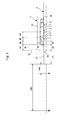
- FIG. 3 is a half sectional view for explaining Experimental Example 1 of the magnetic fluid sealing apparatus according to the present invention.
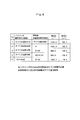
- FIG. 4 is a table showing the measurement results of Experimental Example 1.
- FIG. 5 is a half sectional view for explaining a comparative example 1 of the magnetic fluid seal device according to the present invention.
- FIG. 6 is a table showing the measurement results of Comparative Example 1.
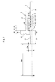
- FIG. 7 is a half sectional view for explaining Experimental Example 2 of the magnetic fluid sealing device according to the present invention.
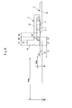
- FIG. 8 is a half cross-sectional view for explaining a comparative example 2 of the magnetic fluid seal device according to the present invention.
- Airtight chamber 1a: Wall surface of airtight chamber
- 2 Rotating shaft
- 2X Magnetic material region
- 2Y Nonmagnetic material region
- 3 Housing
- 3X Magnetic material region
- 3Y Nonmagnetic material region
- 3a hollow part
- 3b flange part
- 4 bearing
- 6 pole piece (magnetic pole piece)
- 7 magnetic fluid
- the magnetic fluid sealing device according to this embodiment is mounted on a wall surface 1a of an airtight chamber 1 of a target device to which the device is applied, and rotatably supports a rotating shaft 2 into which a partial region is inserted in the airtight chamber 1.
- it has a function of maintaining the hermeticity in the hermetic chamber 1, and includes a housing 3, a bearing 4, a magnet 5, a pole piece 6 (magnetic pole piece), and a magnetic fluid 7 as main components.
- the housing 3 is a component constituting the housing of the magnetic fluid seal device, and a hollow portion 3a having a circular cross section penetrating from one end to the other end is formed inside. A part of the rotating shaft 2 is inserted into the airtight chamber 1 through the hollow portion 3a. A flange portion 3b is formed on the outer surface of one end of the housing 3, and the flange portion 3b is fixed to the wall surface 1a of the hermetic chamber 1 by using a fastener such as a bolt (not shown).
- the apparatus is disposed at a boundary portion that separates the hermetic chamber 1 from the external space 100.
- the bearings 4 are assembled near both ends of the housing 3 with the support surfaces exposed on the peripheral surfaces of the hollow portions 3a.
- the rotating shaft 2 inserted through the hollow portion 3a is rotatably supported by these bearings 4.
- an even number of magnets 5 are incorporated in the axial direction at arbitrary intervals.
- the even number of magnets 5 are incorporated in such an arrangement that the end faces in the axial direction of the respective magnets 5 are the same pole.
- the opposing end surfaces of the respective magnets 5 are arranged so as to be S poles or N poles.
- the second and third magnets 5 are provided.
- the opposing end surfaces of the eye magnets 5 may be N poles (or S poles), respectively, and the opposing end surfaces of the third and fourth magnets 5 may be S poles (or N poles).
- a plurality of pole pieces 6 are incorporated in the housing 3 so as to sandwich the plurality of magnets 5.
- These pole pieces 6 are made of a magnetic material, and are arranged so that the inner end face in the radial direction faces the peripheral surface of the rotating shaft 2.
- a magnetic fluid 7 is filled between the inner end surface of the pole pieces 6 facing each other and the peripheral surface of the rotating shaft 2.
- the magnetic fluid 7 is a fluid formed by dispersing magnetic metal fine particles in a colloidal form in a non-magnetic fluid medium.
- a fluid in which ferrite or other magnetic powder is dispersed in a fluid such as hydrocarbon, fluorine carbide, or fatty acid can be used.
- the filled magnetic fluid 7 concentrates on the magnetic flux which forms the magnetic closed circuit which goes out from each of the magnets 5 and passes through the magnetic material portion of each pole piece 6 and the rotating shaft 2 to form a magnetic fluid film.
- the hermetic chamber 1 and the external space 100 are blocked by the magnetic fluid film thus formed, and the hermetic state in the hermetic chamber 1 is maintained.
- a plurality of grooves extending in the circumferential direction are formed on one or both of the inner end surface of the pole piece 6 and the peripheral surface of the rotating shaft 2 facing each other, and the magnetic fluid is formed in the grooves. If 7 is filled, it is preferable that the magnetic fluid 7 can be more firmly retained at the location.
- the rotating shaft 2 and the housing 3 are configured by combining a magnetic material and a non-magnetic material.
- the magnetic material refers to a material having the property of being magnetized by the magnet 5
- the non-magnetic material refers to a material having a property of not being magnetized even when the magnet 5 is brought close.
- the rotating shaft 2 is located in a region S ⁇ b> 2 + ⁇ / b> S ⁇ b> 3 in the hollow portion 3 a of the housing 3 and closer to the hermetic chamber 1 than the pole piece 6 located closest to the hermetic chamber 1.
- a boundary S0 between the nonmagnetic material and the magnetic material is set in the region 2A.
- the region 2X closer to the outer space 100 than the boundary S0 is formed of a magnetic material, and the region 2Y closer to the hermetic chamber 1 than the boundary S0 is not formed.
- the structure is made of a magnetic material.
- the housing 3 is in contact with the pole piece 6 that is closer to the external space 100 than the region H3a that is in contact with the pole piece 6 that is closest to the hermetic chamber 1 and that is adjacent to the pole piece 6.
- An arbitrary region up to the region H3b not to be used is defined as a boundary H0, and a region 3X closer to the hermetic chamber 1 than the boundary H0 is formed of a magnetic material, and a region 3Y closer to the external space 100 than the boundary region is formed of a nonmagnetic material. It has a formed configuration.
- the magnetic force lines generated from the magnet 5 are guided from the magnetic material region of the rotary shaft 2 to the magnetic material region of the housing 3 and returned to the magnet 5.
- a circuit is formed, and the spread of the magnetic field in the direction of the hermetic chamber 1 is suppressed.
- the magnetic material portion of the rotating shaft 2 and the housing 3 is formed of, for example, a steel material, and the nonmagnetic material portion can be formed of a nonmagnetic metal material, a synthetic resin, or the like.
- the joint between both portions is preferably obtained by a joining method by diffusion welding by friction welding, which can provide a strong and smooth surface, but is not limited thereto, and can be joined by welding, screw connection, or any other method .
- the next region S1 to S3 on the rotating shaft 2 is set to either a magnetic material or a nonmagnetic material.
- S1 Area exposed to the airtight chamber 1 side of the housing 3
- S2 Area that has entered the hollow portion 3a by the thickness of the flange portion 3b from the end surface on the airtight chamber 1 side of the housing 3
- S3 In the hollow portion 3a of the housing 3 (2) A region closer to the hermetic chamber 1 than the pole piece 6 located closest to the hermetic chamber 1 and closer to the outer space 100 than the flange portion 3b. Set to either magnetic or non-magnetic material.
- H1 Region where the flange portion 3b is formed
- H2 Region closer to the outer space 100 than the flange portion 3b and closer to the airtight chamber 1 than the pole piece 6 located closest to the airtight chamber 1
- H3 To the airtight chamber 1 Region in contact with the nearest pole piece 6 (H3a in FIG. 2)
- H4 A region from the end of the region of H3 to a central part in contact with the pole piece 6 that is closest to the hermetic chamber 1 and the adjacent pole piece 6
- the measurement results are obtained by appropriately changing the combination of the magnetic material region and the nonmagnetic material region on the rotating shaft 2 and the magnetic material region and the nonmagnetic material region on the housing 3.
- the H1, H2 and H3 regions (H1 + H2 + H3) of the housing 3 are formed of a magnetic material
- the other regions are formed of a nonmagnetic material
- the rotating shaft 2 In the structure in which the S1 and S2 regions (S1 + S2) are formed of a nonmagnetic material and the other regions are formed of a magnetic material, the strength of the magnetic field is remarkably reduced at points A and B (data No. 7).
- the housing 3 cannot obtain a sufficient magnetic shielding effect even if only the flange portion 3b is made of a magnetic material. Since the magnetic material is closed up to the region in contact with the pole piece 6 located closest to the hermetic chamber 1, the shielding effect is exhibited. On the other hand, if the part of the magnetic material straddles the magnet 5, the magnetic field of the magnetic fluid 7 is reduced (30% reduction). Therefore, the pole piece 6 that is closest to the hermetic chamber 1 and the adjacent pole piece 6 It is not preferable to connect the two by the magnetic material portion of the housing 3. If the magnetic material part comes out of the hollow part 3a of the housing 3 to the airtight chamber 1 side in the rotating shaft 2, since the magnetic leakage tip part comes out of the shield, leakage increases.
- Comparative Example 1 of the magnetic fluid seal device according to the present invention will be described with reference to FIGS.
- the present inventor uses a magnetic fluid sealing device having a structure in which one magnet 5 is incorporated in the housing 3, while appropriately changing the above-described conditions (1) and (2).
- the strength of the magnetic field at a point A separated by a distance of 10 mm along the central axis from the end surface of the rotating shaft 2 on the vacuum chamber side and the strength of the magnetic field at a point B separated by a distance of 50 mm were measured.
- the magnetic field strength at point A was 68.7 ⁇ T
- the magnetic field strength at point B was 5.7 ⁇ T, both of which were extremely low magnetic field strengths.
- the comparative example 2 of the magnetic fluid sealing apparatus which concerns on this invention is demonstrated.
- the present inventor rotates three magnets 5 in a housing 3 using a ferrofluid sealing device having a configuration in which the opposite end surfaces of the respective magnets 5 in the axial direction are incorporated as the same pole.
- the strength of the magnetic field at the point A separated by a distance of 10 mm along the central axis from the end surface of the shaft 2 on the airtight chamber side and the strength of the magnetic field at the point B separated by a distance of 50 mm were measured.
- the S1 + S2 region is made of a nonmagnetic material
- the other regions are made of a magnetic material.
- the housing 3 is made of a magnetic material in the region of H1 + H2 + H3 and a nonmagnetic material in the other regions.
- the strength of the magnetic field at point A was 452.4 ⁇ T
- the strength of the magnetic field at point B was 73.4 ⁇ T, both of which were extremely large magnetic field strengths.
- this invention is not limited to embodiment mentioned above, Of course, it can change the design suitably as needed, such as the detailed structure of a magnetic fluid sealing apparatus.
Landscapes
- Engineering & Computer Science (AREA)
- General Engineering & Computer Science (AREA)
- Mechanical Engineering (AREA)
- Sealing Using Fluids, Sealing Without Contact, And Removal Of Oil (AREA)
- Sealing Of Bearings (AREA)
- Rolling Contact Bearings (AREA)
Abstract
Description
特許文献1は、この種の構造を備えた従来の磁性流体シール装置を開示している。
気密室とその外部空間とを仕切る境界部に設けられるとともに、回転軸を挿通する中空部を有するハウジングと、
ハウジングへ軸方向に任意の間隔をおいて並べて組み込まれる複数個の磁石と、
複数個の磁石を挟み込むようにハウジングに組み込まれ、且つ径方向の内側端面を回転軸の周面と対向して配置された複数個のポールピース(磁極片)と、
ポールピースにおける径方向の内側端面と回転軸の周面との間に充填される磁性流体と、を備えている。
また、ポールピースは、磁性材料で形成されている。
そして、回転軸は、ハウジングの中空部内にあって、気密室にもっとも近い位置にあるポールピースよりも気密室寄りに境界を設け、当該境界よりも外部空間寄りの領域が磁性材料で形成され、一方、当該境界よりも気密室寄りの領域が非磁性材料で形成されている。
さらに、ハウジングは、気密室にもっとも近い位置にあるポールピースと接触する領域から、当該領域よりも外部空間寄りであってかつ当該ポールピースと隣接するポールピースには接触しない領域までの間に境界を設け、当該境界よりも気密室寄りの領域が磁性材料で形成され、一方、当該境界よりも外部空間寄りの領域が非磁性材料で形成されている。
なお、ハウジングの軸方向への寸法拡大による大形化を抑制するために、磁石はハウジングに2個又は4個組み込む構成とすることが好ましい。
〔基本構造〕
まず、図1を参照して本発明の実施形態に係る磁性流体シール装置の基本構造を説明する。
本実施形態に係る磁性流体シール装置は、同装置が適用される対象装置の気密室1の壁面1aに装着され、気密室1内に一部領域が挿入される回転軸2を回転自在に支持するとともに、気密室1内の気密性を保持する機能を有しており、ハウジング3、軸受4、磁石5、ポールピース6(磁極片)、磁性流体7を主要な構成部品として備えている。
そして、互いに対向するポールピース6の内側端面と回転軸2の周面との間に、磁性流体7が充填されている。この磁性流体7は、非磁性の流体媒体に磁性体の金属微粒子をコロイド状に分散させることによって形成された流体である。例えば、炭化水素、炭化フッ素、あるいは脂肪酸等の流体にフェライトその他の磁性体粉末を分散した流体を用いることができる。
充填された磁性流体7は、磁石5のそれぞれから出て各ポールピース6及び回転軸2の磁性材料部分を通る磁気閉回路を構成する磁束に集中して、磁性流体膜を構成する。こうして形成された磁性流体膜によって気密室1と外部空間100とが遮断され、気密室1内の気密状態が保持される。
なお、図1に示すように、互いに対向するポールピース6の内側端面と回転軸2の周面のいずれか一方又は双方に周方向に延びる複数本の溝を形成し、この溝内に磁性流体7を充填すれば、磁性流体7をいっそう強固に当該箇所へ留めておくことができて好ましい。
また、ハウジング3は、気密室1にもっとも近い位置にあるポールピース6と接触する領域H3aから、当該領域よりも外部空間100寄りであってかつ当該ポールピース6と隣接するポールピース6には接触しない領域H3bまでの任意の部位を境界H0として、当該境界H0よりも気密室1寄りの領域3Xを磁性材料で形成するとともに、当該境界部位よりも外部空間100寄りの領域3Yを非磁性材料で形成した構成となっている。
このように回転軸2とハウジング3を構成することで、磁石5から発生する磁力線が回転軸2の磁性材料の領域から、ハウジング3の磁性材料の領域へと導かれて磁石5へ帰還する磁気回路が形成され、気密室1方向への磁場の広がりが抑制される。
次に、図3及び図4を参照して、本発明に係る磁性流体シール装置の実験例1について説明する。
本発明者は、図3に示すように、ハウジング3内に2個の磁石5を、各磁石5の対向する軸方向の端面を同じ極として組み込んだ構成の磁性流体シール装置を用いて、次の(1)(2)に示す条件を適宜変更しながら、回転軸2の気密室側の端面から中心軸に沿って10mmの距離だけ離間した地点Aにおける磁場の強さと、同じく50mmの距離だけ離間した地点Bにおける磁場の強さとを計測した。
(1)回転軸2における次のS1~S3の領域を、磁性材料か非磁性材料のいずれかに設定する。
S1:ハウジング3よりも気密室1側に露出した領域
S2:ハウジング3の気密室1側端面からフランジ部3bの厚さ分だけ中空部3a内に入り込んだ領域
S3:ハウジング3の中空部3a内であってフランジ部3bよりも外部空間100寄りで、且つ気密室1にもっとも近い位置にあるポールピース6よりも気密室1寄りの領域
(2)ハウジング3における次のH1~H4の領域を、磁性材料か非磁性材料のいずれかに設定する。
H1:フランジ部3bの形成された領域
H2:フランジ部3bよりも外部空間100寄りで、且つ気密室1にもっとも近い位置にあるポールピース6よりも気密室1寄りの領域
H3:気密室1にもっとも近い位置にあるポールピース6と接触する領域(図2のH3a)
H4:H3の領域端から、気密室1にもっとも近い位置にあるポールピース6と隣接するポールピース6と接触する中央部までの領域
回転軸2は、磁性材料部分がハウジング3の中空部3aから気密室1側へ出てしまうと、磁気漏洩先端部がシールド外部にでることになるため漏洩が大きくなる。ハウジング3の中空部3a内で磁性材料と非磁性材料の境界位置を変更しても磁気漏洩に大きな差はないが、磁性流体7よりも気密室1寄りに当該境界を配置したときもっとも磁気漏洩が小さくなる。
次に、図5及び図6を参照して、本発明に係る磁性流体シール装置の比較例1について説明する。
本発明者は、図5に示すように、ハウジング3内に1個の磁石5を組み込んだ構成の磁性流体シール装置を用いて、上述した(1)(2)に示す条件を適宜変更しながら、回転軸2の真空室側の端面から中心軸に沿って10mmの距離だけ離間した地点Aにおける磁場の強さと、同じく50mmの距離だけ離間した地点Bにおける磁場の強さとを計測した。
次に、図7を参照して、本発明に係る磁性流体シール装置の実験例2について説明する。
本発明者は、図7に示すように、ハウジング3内に4個の磁石5を、各磁石5の対向する軸方向の端面を同じ極として組み込んだ構成の磁性流体シール装置を用いて、回転軸2の気密室側の端面から中心軸に沿って10mmの距離だけ離間した地点Aにおける磁場の強さと、同じく50mmの距離だけ離間した地点Bにおける磁場の強さとを計測した。
回転軸2は、S1+S2の領域を非磁性材料、その他の領域を磁性材料とした。
ハウジング3は、H1+H2+H3の領域を磁性材料、その他の領域を非磁性材料とした。
次に、図8を参照して、本発明に係る磁性流体シール装置の比較例2について説明する。
本発明者は、図8に示すように、ハウジング3内に3個の磁石5を、各磁石5の対向する軸方向の端面を同じ極として組み込んだ構成の磁性流体シール装置を用いて、回転軸2の気密室側の端面から中心軸に沿って10mmの距離だけ離間した地点Aにおける磁場の強さと、同じく50mmの距離だけ離間した地点Bにおける磁場の強さとを計測した。
回転軸2は、S1+S2の領域を非磁性材料、その他の領域を磁性材料とした。
ハウジング3は、H1+H2+H3の領域を磁性材料、その他の領域を非磁性材料とした。
Claims (2)
- 気密室内に一部領域が挿入される回転軸を、前記気密室内の気密性を保持したまま支持する磁性流体シール装置であって、
前記気密室とその外部空間とを仕切る境界部に設けられるとともに、前記回転軸を挿通する中空部を有するハウジングと、
前記ハウジングへ軸方向に任意の間隔をおいて並べて組み込まれる複数個の磁石と、
前記複数個の磁石を挟み込むように前記ハウジングに組み込まれ、且つ径方向の内側端面を前記回転軸の周面と対向して配置された複数個のポールピースと、
前記ポールピースにおける径方向の内側端面と前記回転軸の周面との間に充填される磁性流体と、を備え、
前記磁石は、各磁石の対向する軸方向の端面を同じ極として偶数個を前記ハウジングへ組み込み、
前記ポールピースは、磁性材料で形成し、
前記回転軸は、前記ハウジングの中空部内にあって、前記気密室にもっとも近い位置にあるポールピースよりも気密室寄りに境界を設け、当該境界よりも外部空間寄りの領域を磁性材料で形成するとともに、当該境界よりも気密室寄りの領域を非磁性材料で形成し、
前記ハウジングは、前記気密室にもっとも近い位置にあるポールピースと接触する領域から、当該領域よりも外部空間寄りであってかつ当該ポールピースと隣接するポールピースには接触しない領域までの間に境界を設け、当該境界よりも気密室寄りの領域を磁性材料で形成するとともに、当該境界よりも外部空間寄りの領域を非磁性材料で形成したことを特徴とする磁性流体シール装置。 - 前記磁石は、前記ハウジングに2個又は4個組み込んであること特徴とする請求項1の磁性流体シール装置。
Priority Applications (4)
| Application Number | Priority Date | Filing Date | Title |
|---|---|---|---|
| CN201480056272.1A CN105705808B (zh) | 2013-12-24 | 2014-09-12 | 磁流体密封装置 |
| DE112014005874.2T DE112014005874T5 (de) | 2013-12-24 | 2014-09-12 | Magnetflüssigkeits-Dichteinrichtung |
| KR1020167012347A KR102144274B1 (ko) | 2013-12-24 | 2014-09-12 | 자성유체 실링장치 |
| US15/104,014 US9746084B2 (en) | 2013-12-24 | 2014-09-12 | Magnetic fluid sealing apparatus |
Applications Claiming Priority (2)
| Application Number | Priority Date | Filing Date | Title |
|---|---|---|---|
| JP2013265312A JP6029241B2 (ja) | 2013-12-24 | 2013-12-24 | 磁性流体シール装置 |
| JP2013-265312 | 2013-12-24 |
Publications (1)
| Publication Number | Publication Date |
|---|---|
| WO2015098202A1 true WO2015098202A1 (ja) | 2015-07-02 |
Family
ID=53478084
Family Applications (1)
| Application Number | Title | Priority Date | Filing Date |
|---|---|---|---|
| PCT/JP2014/074172 Ceased WO2015098202A1 (ja) | 2013-12-24 | 2014-09-12 | 磁性流体シール装置 |
Country Status (6)
| Country | Link |
|---|---|
| US (1) | US9746084B2 (ja) |
| JP (1) | JP6029241B2 (ja) |
| KR (1) | KR102144274B1 (ja) |
| CN (1) | CN105705808B (ja) |
| DE (1) | DE112014005874T5 (ja) |
| WO (1) | WO2015098202A1 (ja) |
Families Citing this family (6)
| Publication number | Priority date | Publication date | Assignee | Title |
|---|---|---|---|---|
| WO2018190148A1 (ja) | 2017-04-10 | 2018-10-18 | イーグル工業株式会社 | バタフライバルブ |
| CN109775288B (zh) * | 2019-03-25 | 2024-05-17 | 河北视窗玻璃有限公司 | 一种中空磁性密封板装置 |
| KR102245294B1 (ko) | 2019-06-21 | 2021-04-28 | 세메스 주식회사 | 기판 지지 유닛 및 이를 갖는 기판 처리 장치 |
| CN110939739B (zh) * | 2019-12-16 | 2020-08-21 | 清华大学 | 磁粉、磁性液体联合的密封装置 |
| JP7174799B2 (ja) * | 2021-04-06 | 2022-11-17 | Ckd株式会社 | バタフライバルブ |
| CN118225334B (zh) * | 2024-05-17 | 2024-08-23 | 常州市沐泽流体科技有限公司 | 一种矿机冷却管气密性检测设备 |
Citations (2)
| Publication number | Priority date | Publication date | Assignee | Title |
|---|---|---|---|---|
| JPS5898697A (ja) * | 1981-12-09 | 1983-06-11 | Hitachi Ltd | 密封式送風機 |
| JPH04321881A (ja) * | 1991-04-23 | 1992-11-11 | Tokin Corp | 磁気シール回転導入機 |
Family Cites Families (16)
| Publication number | Priority date | Publication date | Assignee | Title |
|---|---|---|---|---|
| JPS5950275A (ja) * | 1982-09-16 | 1984-03-23 | Rigaku Keisoku Kk | 磁性流体軸封装置 |
| US4995622A (en) * | 1989-02-07 | 1991-02-26 | Nippon Pillar Packing Co., Ltd. | Magnetic fluid seal device |
| JPH07174239A (ja) * | 1993-12-21 | 1995-07-11 | Seiko Seiki Co Ltd | シール機構 |
| JPH08320083A (ja) * | 1995-05-24 | 1996-12-03 | Rigaku Corp | 磁気シール装置 |
| JPH10169789A (ja) * | 1996-12-03 | 1998-06-26 | Rigaku Corp | 磁気シール装置 |
| JP4073064B2 (ja) | 1997-12-02 | 2008-04-09 | 株式会社リガク | 耐磁場磁性流体シール装置 |
| JP3766866B2 (ja) * | 2002-04-04 | 2006-04-19 | 独立行政法人物質・材料研究機構 | 磁性流体シール回転軸受け |
| JP2003314705A (ja) * | 2002-04-25 | 2003-11-06 | Nok Corp | 磁性流体を利用した密封装置 |
| CN1245583C (zh) * | 2003-11-18 | 2006-03-15 | 北京交通大学 | 低温大直径磁性液体密封装置 |
| CN100360839C (zh) * | 2006-08-01 | 2008-01-09 | 中国兵器工业第五二研究所 | 一种磁性液体密封装置 |
| CN201027988Y (zh) * | 2007-04-29 | 2008-02-27 | 浙江工业大学 | 真空设备传动轴用磁流体密封传动装置 |
| WO2010014563A1 (en) * | 2008-07-30 | 2010-02-04 | Rigaku Innovative Technologies, Inc. | Magnetic fluid seal with shunt element |
| CN102216658A (zh) * | 2009-09-24 | 2011-10-12 | 伊格尔工业股份有限公司 | 密封装置 |
| CN101769381B (zh) * | 2010-03-01 | 2012-01-11 | 北京交通大学 | 一种磁性液体与c型滑环组合式往复轴密封装置 |
| TW201204966A (en) * | 2010-07-23 | 2012-02-01 | qi-yun Gong | Magnetic fluid sealing device |
| US8531195B2 (en) * | 2010-08-26 | 2013-09-10 | Ferrotec (Usa) Corporation | Failure indicator seal for a rotary feedthrough |
-
2013
- 2013-12-24 JP JP2013265312A patent/JP6029241B2/ja active Active
-
2014
- 2014-09-12 WO PCT/JP2014/074172 patent/WO2015098202A1/ja not_active Ceased
- 2014-09-12 CN CN201480056272.1A patent/CN105705808B/zh active Active
- 2014-09-12 US US15/104,014 patent/US9746084B2/en active Active
- 2014-09-12 KR KR1020167012347A patent/KR102144274B1/ko active Active
- 2014-09-12 DE DE112014005874.2T patent/DE112014005874T5/de not_active Withdrawn
Patent Citations (2)
| Publication number | Priority date | Publication date | Assignee | Title |
|---|---|---|---|---|
| JPS5898697A (ja) * | 1981-12-09 | 1983-06-11 | Hitachi Ltd | 密封式送風機 |
| JPH04321881A (ja) * | 1991-04-23 | 1992-11-11 | Tokin Corp | 磁気シール回転導入機 |
Also Published As
| Publication number | Publication date |
|---|---|
| KR20160102158A (ko) | 2016-08-29 |
| JP2015121263A (ja) | 2015-07-02 |
| JP6029241B2 (ja) | 2016-11-24 |
| KR102144274B1 (ko) | 2020-08-13 |
| US9746084B2 (en) | 2017-08-29 |
| DE112014005874T5 (de) | 2016-09-15 |
| CN105705808B (zh) | 2018-01-05 |
| US20160312899A1 (en) | 2016-10-27 |
| CN105705808A (zh) | 2016-06-22 |
Similar Documents
| Publication | Publication Date | Title |
|---|---|---|
| JP6029241B2 (ja) | 磁性流体シール装置 | |
| US5826885A (en) | Magnetic fluid sealing device | |
| JP5651596B2 (ja) | 圧縮可能リングによりベアリングとシャフトを中心に配置する磁性流体封止装置 | |
| US6857635B1 (en) | Ultra high vacuum ferrofluidic seals and method of manufacture | |
| US10756612B2 (en) | Eddy current deceleration device | |
| JP6464407B2 (ja) | 磁性流体シールの組立方法及び磁性流体シール | |
| JP5024965B2 (ja) | 磁性流体シール装置 | |
| JPS61165073A (ja) | 共軸の多重シヤフトの磁性流体シ−ル装置 | |
| WO2019008372A1 (en) | MAGNETIC BEARING | |
| JP2007010030A5 (ja) | ||
| JPH08320083A (ja) | 磁気シール装置 | |
| CN112963538A (zh) | 一种磁粉与磁性液体组合密封装置 | |
| JP2006144783A (ja) | 高速回転ロータを有する真空ポンプのフランジと結合可能な破損防止装置 | |
| US10432055B2 (en) | Motor, actuator, semiconductor manufacturing apparatus, and flat display manufacturing apparatus | |
| JP3773132B2 (ja) | 磁気シール装置 | |
| JP6096063B2 (ja) | サイクロトロン | |
| JP2015117755A (ja) | ころがり軸受 | |
| JP2006109654A (ja) | モータシステム | |
| JP4140309B2 (ja) | 磁性流体を利用した密封装置 | |
| JPH0771620A (ja) | 磁性流体シール装置 | |
| PL242027B1 (pl) | Uszczelnienie ochronne łożyska tocznego z cieczą magnetyczną | |
| JP2577238B2 (ja) | 磁性流体を利用した耐圧シール装置 | |
| JP2006296058A (ja) | ダイレクトドライブモータ | |
| JP2011127616A (ja) | 磁気粘性流体を使用したシール手段を有する回転装置 | |
| JP2003269624A (ja) | 磁性流体シール |
Legal Events
| Date | Code | Title | Description |
|---|---|---|---|
| 121 | Ep: the epo has been informed by wipo that ep was designated in this application |
Ref document number: 14873733 Country of ref document: EP Kind code of ref document: A1 |
|
| ENP | Entry into the national phase |
Ref document number: 20167012347 Country of ref document: KR Kind code of ref document: A |
|
| WWE | Wipo information: entry into national phase |
Ref document number: 15104014 Country of ref document: US |
|
| WWE | Wipo information: entry into national phase |
Ref document number: 112014005874 Country of ref document: DE |
|
| 122 | Ep: pct application non-entry in european phase |
Ref document number: 14873733 Country of ref document: EP Kind code of ref document: A1 |