WO2015098081A1 - 細胞培養装置および細胞培養方法 - Google Patents
細胞培養装置および細胞培養方法 Download PDFInfo
- Publication number
- WO2015098081A1 WO2015098081A1 PCT/JP2014/006369 JP2014006369W WO2015098081A1 WO 2015098081 A1 WO2015098081 A1 WO 2015098081A1 JP 2014006369 W JP2014006369 W JP 2014006369W WO 2015098081 A1 WO2015098081 A1 WO 2015098081A1
- Authority
- WO
- WIPO (PCT)
- Prior art keywords
- pipette
- unit
- culture
- moving
- cell culture
- Prior art date
Links
Images


Classifications
-
- C—CHEMISTRY; METALLURGY
- C12—BIOCHEMISTRY; BEER; SPIRITS; WINE; VINEGAR; MICROBIOLOGY; ENZYMOLOGY; MUTATION OR GENETIC ENGINEERING
- C12M—APPARATUS FOR ENZYMOLOGY OR MICROBIOLOGY; APPARATUS FOR CULTURING MICROORGANISMS FOR PRODUCING BIOMASS, FOR GROWING CELLS OR FOR OBTAINING FERMENTATION OR METABOLIC PRODUCTS, i.e. BIOREACTORS OR FERMENTERS
- C12M41/00—Means for regulation, monitoring, measurement or control, e.g. flow regulation
- C12M41/48—Automatic or computerized control
-
- C—CHEMISTRY; METALLURGY
- C12—BIOCHEMISTRY; BEER; SPIRITS; WINE; VINEGAR; MICROBIOLOGY; ENZYMOLOGY; MUTATION OR GENETIC ENGINEERING
- C12M—APPARATUS FOR ENZYMOLOGY OR MICROBIOLOGY; APPARATUS FOR CULTURING MICROORGANISMS FOR PRODUCING BIOMASS, FOR GROWING CELLS OR FOR OBTAINING FERMENTATION OR METABOLIC PRODUCTS, i.e. BIOREACTORS OR FERMENTERS
- C12M23/00—Constructional details, e.g. recesses, hinges
- C12M23/48—Holding appliances; Racks; Supports
-
- C—CHEMISTRY; METALLURGY
- C12—BIOCHEMISTRY; BEER; SPIRITS; WINE; VINEGAR; MICROBIOLOGY; ENZYMOLOGY; MUTATION OR GENETIC ENGINEERING
- C12M—APPARATUS FOR ENZYMOLOGY OR MICROBIOLOGY; APPARATUS FOR CULTURING MICROORGANISMS FOR PRODUCING BIOMASS, FOR GROWING CELLS OR FOR OBTAINING FERMENTATION OR METABOLIC PRODUCTS, i.e. BIOREACTORS OR FERMENTERS
- C12M23/00—Constructional details, e.g. recesses, hinges
- C12M23/50—Means for positioning or orientating the apparatus
-
- C—CHEMISTRY; METALLURGY
- C12—BIOCHEMISTRY; BEER; SPIRITS; WINE; VINEGAR; MICROBIOLOGY; ENZYMOLOGY; MUTATION OR GENETIC ENGINEERING
- C12M—APPARATUS FOR ENZYMOLOGY OR MICROBIOLOGY; APPARATUS FOR CULTURING MICROORGANISMS FOR PRODUCING BIOMASS, FOR GROWING CELLS OR FOR OBTAINING FERMENTATION OR METABOLIC PRODUCTS, i.e. BIOREACTORS OR FERMENTERS
- C12M29/00—Means for introduction, extraction or recirculation of materials, e.g. pumps
-
- C—CHEMISTRY; METALLURGY
- C12—BIOCHEMISTRY; BEER; SPIRITS; WINE; VINEGAR; MICROBIOLOGY; ENZYMOLOGY; MUTATION OR GENETIC ENGINEERING
- C12M—APPARATUS FOR ENZYMOLOGY OR MICROBIOLOGY; APPARATUS FOR CULTURING MICROORGANISMS FOR PRODUCING BIOMASS, FOR GROWING CELLS OR FOR OBTAINING FERMENTATION OR METABOLIC PRODUCTS, i.e. BIOREACTORS OR FERMENTERS
- C12M33/00—Means for introduction, transport, positioning, extraction, harvesting, peeling or sampling of biological material in or from the apparatus
- C12M33/04—Means for introduction, transport, positioning, extraction, harvesting, peeling or sampling of biological material in or from the apparatus by injection or suction, e.g. using pipettes, syringes, needles
Definitions
- the present invention relates to cell culture.
- a culture medium is a culture solution containing a large amount of nutrients.
- the pH of the medium is lowered due to the influence of lactic acid and the like generated along with cell growth.
- the culture of the cells may become inactive, outside the pH range suitable for cell culture. Therefore, in the conventional cell culture apparatus, the medium is exchanged at regular time intervals according to the detected cell type (see, for example, Patent Document 1).
- FIG. 8 shows the cell culture apparatus 101 of Patent Document 1.
- the medium is replaced by the replacement unit 102 or the test substance is added by the addition unit 103 to the culture unit 105 according to the type of cell detected by the detection unit 104.
- the medium is generally exchanged manually using a pipette.
- An object of the present invention is to provide a cell culture apparatus or a cell culture direction that can automate the exchange of a culture medium.
- a cell culture device is a cell culture device for culturing cells using a medium in a culture container, and a pump connected to a pipette held by a first holding unit.
- a first moving unit that moves the first holding unit, a second holding unit that holds the culture vessel, a second moving unit that holds and moves the culture vessel, and a control unit,
- the control unit moves the lid of the culture container in parallel in the horizontal direction by the second moving unit.
- the second moving unit is controlled so as to be in an open state.
- the cell culture method of the present invention is a cell culture method for culturing cells using a medium in a culture container, wherein the first holding unit holds the pipette, and the second moving unit. After holding and moving the culture container, the pipette held by the first holding part is attached to the culture container with the lid of the culture container being translated in the horizontal direction by the second moving part. The liquid is aspirated or discharged into the culture vessel.
- FIG. 1 is a diagram showing an outline of a cell culture device in the present embodiment
- FIG. 2 is a flowchart of medium replacement in the present embodiment
- FIG. 3 is a diagram showing an outline of the pump in the present embodiment.
- FIG. 4A is a diagram showing a state at the completion of liquid injection in the present embodiment
- FIG. 4B is a diagram showing a state at the completion of liquid injection in the reference example
- FIG. 5A is a schematic plan view at the time of the first stripping liquid discharge in the present embodiment
- FIG. 5B is a schematic side view when the first release liquid is discharged in the present embodiment
- FIG. 5C is a schematic plan view when the second stripping liquid is discharged in the present embodiment.
- FIG. 5A is a schematic plan view at the time of the first stripping liquid discharge in the present embodiment
- FIG. 5B is a schematic side view when the first release liquid is discharged in the present embodiment
- FIG. 5C is a schematic plan view when the second stripping liquid is discharged in
- FIG. 5D is a schematic side view when the second stripping liquid is discharged in the present embodiment.
- FIG. 6 is a view for explaining pipette removal in the present embodiment.
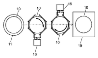
- FIG. 7 is a diagram for explaining a state when the culture container is moved in the present embodiment.
- FIG. 8 is a schematic view of a conventional cell culture apparatus.
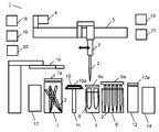
- FIG. 1 is a diagram showing an outline of a cell culture device 1 according to an embodiment of the present invention.
- the cell culture device according to the present embodiment includes at least a first holding unit 3, a pump 4, a first moving unit 5, a second holding unit 11, a second moving unit 16, and a control unit 15. .
- the first holding unit 3 is, for example, a pipette holding unit, and fixes and holds the pipette 2 (pipette tip) with an elastic member such as a spring.
- the first moving unit 5 is, for example, a pipette moving unit, and moves the pipette 2 held by the first holding unit 3.
- the second holding unit 11 is, for example, a culture container holding unit, and holds a plurality of culture containers 10 by protrusions.
- the second moving unit 16 is a culture vessel moving unit such as a manipulator, and grips and moves the culture vessel 10.
- the control unit 15 controls the operation of each component in the apparatus. The control by the control unit 15 is performed according to a preset condition or a condition input by the operation unit 13 such as a touch panel.
- the pipette 2 is connected to the pump 4 via the first holding unit 3.
- the pipette 2 discharges / sucks liquid using the pump 4 as a power source.
- the first moving unit 5 moves the first holding unit 3 in the apparatus.
- the first storage unit 6 is a spare pipette storage unit, for example, and stores the spare pipette 2.
- the second storage unit 7 is, for example, a discard pipette storage unit, in which the used pipette 2 is discarded.
- the tube holding unit 9 holds a plurality of tubes 8.
- the tube 8 is a container for storing various liquids. One tube 8 stores a replacement medium, and another tube 8 stores a stripping solution.
- the second holding unit 11 can hold the culture vessel 10.
- the tank 12 is a waste liquid tank, for example, and the used medium is discarded.
- the second moving unit 16 can grip and move the culture vessel 10.
- the second holding unit 11 can hold a plurality of culture vessels 10. In addition, by rotating the second holding unit 11, it is possible to change the positions of the plurality of culture vessels 10.
- a first lid 6a which is a lid for a spare pipette, is provided on the vertical upper side of the first storage unit 6.
- a third lid 9 a that is a tube lid is provided on the vertical upper side of the tube holding portion 9.
- a second lid 7a that is a lid for a waste pipette is provided on the vertical upper side of the second storage unit 7.
- a fourth lid 12a which is a tank lid, is provided on the vertical upper side of the tank 12.
- the first lid 6a and the third lid 9a are provided to prevent surrounding dust or liquid from entering the spare pipette 2 or the tube 8.
- the second lid 7a and the fourth lid 12a are provided to prevent the liquid and waste liquid in the pipette 2 to be discarded from being scattered around.
- the culture vessel 10 has a lid 10a.
- the lid of the culture container 10 is once closed by the second moving unit 16. After being lifted up vertically, it can be opened by parallel translation in the horizontal direction.
- the cell culture device 1 includes a centrifuge 14, a heater 17, a refrigerator 18, an incubator 19, and a third storage unit 20.
- the centrifuge 14 separates the medium and the cells by centrifuging the medium containing the cells.
- the heater 17 heats the medium, and the refrigerator 18 stores the reagent such as the medium contained in the tube 8 or the like at a low temperature.
- the incubator 19 cultures the cells in the culture vessel 10 under predetermined conditions.
- the third storage unit 20 stores the spare culture container 10.
- the third storage unit 20 is a culture container storage unit, for example, and stores an empty culture container 10.
- the refrigerator 18, the incubator 19, and the third storage unit 20 are arranged at positions that do not prevent the second moving unit 16 from moving the culture vessel 10. Further, the heater 17 and the centrifuge 14 are arranged at positions where the pipette 2 held by the first holding unit 3 and the tip of the second moving unit 16 can move.
- the second moving unit 16 opens the door of the incubator 19 in step S01 of FIG. Next, the second moving unit 16 takes out the target culture container 10 from the plurality of culture containers 10 stored in the incubator 19. Then, the second moving unit 16 moves the target culture vessel 10 onto the second holding unit 11, and holds the target culture vessel 10 with the second holding unit 11. Thereafter, the door of the incubator 19 is closed by an opening / closing mechanism built in the incubator 19.
- the example in which the culture container 10 containing the cells being cultured is stored in the incubator 19 has been described.
- another storage unit for example, the third storage unit 20
- Etc. may be taken out of the culture vessel 10.
- step S02 the first moving unit 5 moves the first holding unit 3 above the first storage unit 6. Then, the first lid 6 a is opened, and the first holding unit 3 holds the first pipette 2 among the plurality of pipettes 2 stored in the first storage unit 6. Thereafter, the first lid 6 a is closed by an opening / closing mechanism built in the first storage unit 6. The first holding unit 3 holds the pipette 2 by inserting and fixing the first holding unit 3 to the pipette 2.
- step S03 the first moving unit 5 moves the first holding unit 3 above the second holding unit 11. Then, the second moving unit 16 translates the lid 10a of the culture vessel 10 in the horizontal direction immediately before suction or discharge.
- the first pipette 2 aspirates the medium in the culture vessel 10 before the exchange by the suction operation using the pump 4 as a power source in a state where the lid 10a is opened by the parallel movement of the lid 10a. Thereafter, the lid 10 a of the culture vessel 10 is returned to the original position by the first moving unit 5.
- step S04 the first moving unit 5 moves the first holding unit 3 above the tank 12.
- the medium before exchange that has been sucked into the first pipette 2 in a state where the fourth lid 12a is opened by the opening / closing mechanism built in the tank 12 is discharged by the discharge operation using the pump 4 as a power source. It is discharged and discarded. Thereafter, the fourth lid 12a is closed by the aforementioned opening / closing mechanism.
- step S05 the first moving unit 5 moves the first holding unit 3 above the second storage unit 7.
- the second lid 7 a is opened by the opening / closing mechanism built in the second storage unit 7, and the used first pipette 2 is discarded in the second storage unit 7.
- the second lid 7a is closed by the aforementioned opening / closing mechanism.
- the discarding operation of the pipette 2 is as follows.
- the actuator 7b shown in FIG. 6
- the first holding unit 3 is moved to the left and right
- a rotational moment is generated in the pipette 2.
- the pipette 2 is removed from the first holding unit 3 and discarded in the second storage unit 7. Details of how to remove the pipette 2 will be described later with reference to FIG.
- step S06 the second pipette 2 is inserted and held in the first holding unit 3 in the same procedure as in step S02.
- step S07 the first moving unit 5 moves the first holding unit 3 above the tube holding unit 9. Then, the third lid 9a is opened by the opening / closing mechanism built in the tube holding section 9, and the second pipette 2 aspirates the cell peeling solution in the tube 8 by the suction operation using the pump 4 as a power source. Thereafter, the third lid 9a is closed by the aforementioned opening / closing mechanism.
- the cell detachment liquid is a liquid for detaching the cells attached on the culture vessel 10. For example, trypsin is used as the cell peeling solution.
- step S08 the first moving unit 5 moves the first holding unit 3 above the second holding unit 11.
- the second moving unit 16 translates the lid 10a of the culture vessel 10 in the horizontal direction.
- the second pipette 2 discharges the stripping solution into the culture vessel 10 by a discharge operation using the pump 4 as a power source. Thereafter, the lid 10a of the culture vessel 10 is returned to its original position.
- step S09 the culture vessel 10 is rocked by the rocking mechanism built in the second holding unit 16, and the cells are detached from the culture vessel 10.
- step S ⁇ b> 10 the first moving unit 5 moves the first holding unit 3 above the second storage unit 7. Then, the second lid 7 a is opened by the opening / closing mechanism built in the second storage unit 7, and the used second pipette 2 is discarded in the second storage unit 7. Thereafter, the second lid 7a is closed by the aforementioned opening / closing mechanism.
- step S11 the first holding unit 3 holds the third pipette 2 in the same procedure as in step S02.
- step S ⁇ b> 12 the first moving unit 5 moves the first holding unit 3 above the tube holding unit 9. Then, the third lid 9a is opened by an opening / closing mechanism built in the tube holding portion 9. Then, the third pipette 2 sucks the exchanged medium (new medium) in the tube 8 by the suction operation using the pump 4 as a power source. Thereafter, the third lid 9a is closed by the aforementioned opening / closing mechanism.
- step S ⁇ b> 13 the first moving unit 5 moves the first holding unit 3 above the second holding unit 11.
- the second moving unit 16 translates the lid 10a of the culture vessel 10 in the horizontal direction.
- the pipette 2 discharges the exchanged medium (new medium) into the culture vessel 10 by a discharge operation using the pump 4 as a power source.
- the lid 10 a of the culture vessel 10 is returned to the original position by the second moving unit 16.
- step S ⁇ b> 14 the first moving unit 5 moves the first holding unit 3 above the second storage unit 7. Then, the second lid 7 a is opened by the opening / closing mechanism built in the second storage unit 7, and the used third pipette 2 is discarded in the second storage unit 7. Thereafter, the second lid 7a is closed by the aforementioned opening / closing mechanism.
- step S15 after the door of the incubator 19 is opened by the opening / closing mechanism built in the incubator 19, the second moving unit 16 moves and stores the culture vessel 10 in the incubator 19. Thereafter, the door of the incubator 19 is closed by the aforementioned opening / closing mechanism.
- the medium is exchanged by the above-described flows with reference to FIG.
- the culture vessel 10 it is preferable to image and observe the inside of the culture vessel 10 with a camera at least at any timing after step S01, after step S03, and after step S13. Observing at these timings makes it possible to adjust the amount of medium before and after replacement and the type and amount of stripping solution according to the observation results. Therefore, the accuracy of cell culture can be further increased.
- the pump 4 of the cell culture device 1 will be described with reference to FIG.
- the pump 4 of this Embodiment is a syringe pump, for example, and is comprised by the three-way valve 4a, the syringe 4b, and the flow path 4c.
- the origin position of the syringe 4b with a volume of 25 ml is set to a position of 5 ml instead of a position of 0 ml.
- the origin position is indicated by X in FIG. That is, in the present embodiment, the origin position of the plunger 4d of the syringe 4b is set to a position shifted in the suction direction by a predetermined amount from the discharge limit position.
- the origin position is set by the control unit 15 controlling the pump 4. That is, the control unit 15 controls the pump 4 so that the origin position of the pump 4 is set to a position shifted in the suction direction from the discharge limit position.
- the syringe 4b and the pipette 2 are piped by the flow path 4c through the three-way valve 4a.
- the syringe 4b returns to the origin position.
- the three-way valve 4a is temporarily switched to the open side while the pipette 2 is inserted into the tube 8. Then, the pump 4 sucks air.
- the three-way valve 4a is switched to the open side (pipette 2 side) and the plunger 4d is returned to the origin position, and then the liquid (medium or stripping solution) in the tube 8 is sucked. If a liquid (medium or stripping solution) remains at the tip of the pipette 2, an inner membrane is formed at the tip of the pipette 2. Therefore, these operations are performed for the purpose of preventing the inner membrane from being formed.
- step S13 in FIG. 2 will be described in detail with reference to FIGS. 4A and 4B.
- the discharge of the liquid (medium) is completed in a state where the tip of the pipette 2 is located on the liquid level of the medium. That is, when the discharge of the liquid is completed, the tip of the pipette 2 is positioned on the liquid surface of the liquid (medium).
- the position of the tip of the pipette 2 is controlled by the control unit 15 controlling the first moving unit 5.
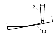
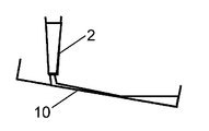
- the stripping solution is discharged twice, and the culture vessel 10 is tilted in the opposite direction between the first discharge and the second discharge.
- a stripping solution is discharged onto the inner wall surface of the steel sheet.
- the culture vessel 10 is tilted in the opposite direction between the first discharge (shown in FIG. 5B) and the second discharge (shown in FIG. 5D). It is done.
- the pipette 2 discharges the stripping solution while moving from a high position on the inclined surface of the culture container 10 toward a low position.
- the force for removing the pipette 2 requires a larger force than when the pipette 2 is attached. In this case, the attachment state of various structures may be shifted due to an impact when the pipette 2 is removed. On the other hand, in the method described above in the present embodiment, the pipette 2 can be removed smoothly.
- the control unit 15 controls the first moving unit 5 so that when the pipette 2 is removed from the first holding unit 3, the first holding unit 3 moves left and right while moving upward.
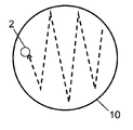
- the second moving unit 16 moves the culture vessel 10 in detail with reference to FIG.
- a force in a certain direction is applied to the medium and cells in the culture vessel 10 due to reaction and inertia caused by the movement. Therefore, in this case, the cells in the culture container 10 may be biased. Therefore, in the present embodiment, in order to prevent the cells from being biased, the second moving unit 16 is moved while rotating the culture vessel 10 as shown in FIG. That is, in the present embodiment, when the culture vessel 10 moves, the phase / posture of the culture vessel 10 is dynamically changed according to the movement trajectory.
- the control unit 15 controls the second moving unit 16 so that the culture vessel 10 moves relative to the second holding unit and the culture vessel 10 moves while rotating.
- the second moving unit 16 not only rotates the culture vessel 10 but also moves it vertically downward. By moving the culture vessel 10 downward, it is considered that the possibility of cell bias can be further reduced.
- the control unit 15 performs the second movement so that the culture vessel 10 moves while rotating and moves vertically downward. The unit 16 is controlled.
- the cell culture device of the present invention is useful for cell culture in the field of regenerative medicine and drug discovery.
Landscapes
- Health & Medical Sciences (AREA)
- Chemical & Material Sciences (AREA)
- Life Sciences & Earth Sciences (AREA)
- Engineering & Computer Science (AREA)
- Organic Chemistry (AREA)
- Wood Science & Technology (AREA)
- Bioinformatics & Cheminformatics (AREA)
- Zoology (AREA)
- General Health & Medical Sciences (AREA)
- Microbiology (AREA)
- Biomedical Technology (AREA)
- Biochemistry (AREA)
- General Engineering & Computer Science (AREA)
- Biotechnology (AREA)
- Genetics & Genomics (AREA)
- Sustainable Development (AREA)
- Analytical Chemistry (AREA)
- Clinical Laboratory Science (AREA)
- Computer Hardware Design (AREA)
- Molecular Biology (AREA)
- Apparatus Associated With Microorganisms And Enzymes (AREA)
- Micro-Organisms Or Cultivation Processes Thereof (AREA)
Abstract
Description
図1は、本発明の実施の形態における細胞培養装置1の概要を示す図である。本実施の形態の細胞培養装置は、少なくとも、第1保持部3と、ポンプ4と、第1移動部5と、第2保持部11と、第2移動部16と、制御部15とを有する。第1保持部3は、例えばピペット保持部であり、バネ等の弾性部材でピペット2(ピペットチップ)を固定して保持する。第1移動部5は、例えばピペット移動部であり、第1保持部3に保持されたピペット2を移動させる。第2保持部11は、例えば培養容器保持部であり、複数の培養容器10を突起により保持する。第2移動部16は、例えばマニピュレータなどの培養容器移動部であり、培養容器10を把持して移動させる。制御部15は、装置内の各構成の動作を制御する。制御部15による制御は、予め設定された条件、もしくは、タッチパネル等の操作部13により入力された条件に従って行われる。
2 ピペット
3 第1保持部
4 ポンプ
4a 三方弁
4b シリンジ
4c 流路
4d プランジャ
5 第1移動部
6 第1保管部
6a 第1蓋
7 第2保管部
7a 第2蓋
7b アクチュエータ
8 チューブ
9 チューブ保持部
9a 第3蓋
10 培養容器
10a 蓋
11 第2保持部
12 タンク
12a 第4蓋
13 操作部
14 遠心分離機
15 制御部
16 第2移動部
17 ヒータ
18 冷蔵庫
19 インキュベータ
20 第3保管部
Claims (10)
- 培養容器内の培地を用いて細胞を培養する細胞培養装置であって、
第1保持部で保持されたピペットに接続されるポンプと、
前記第1保持部を移動させる第1移動部と、
前記培養容器を保持する第2保持部と、
前記培養容器を把持して移動させる第2移動部と、
制御部と、を備え、
前記制御部は、前記ピペットが、前記培養容器の液体を吸引、または、前記培養容器へ液体を吐出する時、前記培養容器の蓋を前記第2移動部によって水平方向に平行移動させることで蓋が開いた状態になるように前記第2移動部を制御する、
細胞培養装置。 - 前記制御部は、前記剥離液を前記培養容器内に2回吐出する時、1回目の吐出時と2回目の吐出時とで互いに逆方向に前記培養容器が傾くように前記第2保持部を制御する、
請求項1に記載の細胞培養装置。 - 前記制御部は、前記ピペットからの吐出開始時において前記培養容器の鉛直上側の内壁面を吐出の開始位置とするとともに、前記ピペットの先端が対向する位置が前記培養容器の傾斜面の高い位置から低い位置に向かって動くように、前記第1移動部を制御する、
請求項1または2に記載の細胞培養装置。 - 前記制御部は、前記培養容器が前記第2保持部に対して相対的に移動し、かつ、前記培養容器が回転しながら移動するように、前記第2移動部を制御する、
請求項1から3いずれか1項に記載の細胞培養装置。 - 前記制御部は、前記培養容器が前記第2保持部に対して相対的に移動する時、前記培養容器鉛直下方に向かって移動するように、前記第2移動部を制御する、
請求項4に記載の細胞培養装置。 - 前記制御部は、前記培養容器に対する前記液体の吐出が完了する時、前記ピペットの先端が前記培養容器内の培地の液面に位置するように、前記第1移動部を制御する、
請求項1から5いずれか1項に記載の細胞培養装置。 - 前記制御部は、前記第1保持部から前記ピペットが取り外される時、前記第1保持部が前記ピペットに対して相対的に上方に移動しながら左右に動くように、前記第1移動部を制御する、
請求項1から6いずれか1項に記載の細胞培養装置。 - 前記制御部は、前記ポンプの原点位置が吐出限界位置より吸引方向にシフトした位置に設定されるように、前記ポンプを制御する、
請求項1から7いずれか1項に記載の細胞培養装置。 - 予備ピペットを保管する第1保管部と、培地が入ったチューブを保持するチューブ保持部と、培地を廃棄するためのタンクと、廃棄ピペットを保管する第2保管部とを、さらに備え、
前記第1保管部、前記チューブ保持部、前記タンク、及び、前記第2保管部は、それぞれ蓋を備える、
請求項1から8いずれか1項に記載の細胞培養装置。 - 培養容器内の培地を用いて細胞を培養する細胞培養方法であって、
第1保持部がピペットを保持し、
第2移動部が前記培養容器を把持して移動させた後、
前記培養容器の蓋が前記第2移動部によって水平方向に平行移動した状態で、前記第1保持部に保持された前記ピペットが前記培養容器の液体を吸引または前記培養容器へ液体を吐出する、
細胞培養方法。
Priority Applications (3)
| Application Number | Priority Date | Filing Date | Title |
|---|---|---|---|
| JP2015532205A JP5866578B2 (ja) | 2013-12-27 | 2014-12-22 | 細胞培養装置および細胞培養方法 |
| US14/891,997 US10202576B2 (en) | 2013-12-27 | 2014-12-22 | Apparatus for culturing cells |
| EP14873295.1A EP2980202B1 (en) | 2013-12-27 | 2014-12-22 | Cell culture apparatus and cell culture method |
Applications Claiming Priority (2)
| Application Number | Priority Date | Filing Date | Title |
|---|---|---|---|
| JP2013-271273 | 2013-12-27 | ||
| JP2013271273 | 2013-12-27 |
Publications (1)
| Publication Number | Publication Date |
|---|---|
| WO2015098081A1 true WO2015098081A1 (ja) | 2015-07-02 |
Family
ID=53477979
Family Applications (1)
| Application Number | Title | Priority Date | Filing Date |
|---|---|---|---|
| PCT/JP2014/006369 WO2015098081A1 (ja) | 2013-12-27 | 2014-12-22 | 細胞培養装置および細胞培養方法 |
Country Status (4)
| Country | Link |
|---|---|
| US (1) | US10202576B2 (ja) |
| EP (1) | EP2980202B1 (ja) |
| JP (1) | JP5866578B2 (ja) |
| WO (1) | WO2015098081A1 (ja) |
Cited By (3)
| Publication number | Priority date | Publication date | Assignee | Title |
|---|---|---|---|---|
| WO2019177135A1 (ja) * | 2018-03-15 | 2019-09-19 | テルモ株式会社 | シート状細胞培養物の製造方法 |
| JP2021016324A (ja) * | 2019-07-18 | 2021-02-15 | 株式会社島津製作所 | 細胞継代装置および細胞継代装置の制御方法 |
| JP7486160B2 (ja) | 2020-05-25 | 2024-05-17 | パナソニックIpマネジメント株式会社 | 細胞培養装置および細胞培養方法 |
Families Citing this family (1)
| Publication number | Priority date | Publication date | Assignee | Title |
|---|---|---|---|---|
| CN106244456B (zh) * | 2016-08-29 | 2019-05-10 | 杭州键一生物科技有限公司 | 全自动智能培养箱及其控制方法 |
Citations (5)
| Publication number | Priority date | Publication date | Assignee | Title |
|---|---|---|---|---|
| JP2004305148A (ja) * | 2003-04-09 | 2004-11-04 | Olympus Corp | 自動培養装置 |
| JP2007024576A (ja) | 2005-07-13 | 2007-02-01 | Fujifilm Holdings Corp | 細胞重層培養物における毒性試験装置 |
| JP2012152124A (ja) * | 2011-01-25 | 2012-08-16 | Nikon Corp | 培養観察装置 |
| WO2012132148A1 (ja) * | 2011-03-28 | 2012-10-04 | 三洋電機株式会社 | 分注装置および分注システム |
| JP2013017461A (ja) * | 2011-07-14 | 2013-01-31 | Panasonic Healthcare Co Ltd | 分注装置 |
Family Cites Families (2)
| Publication number | Priority date | Publication date | Assignee | Title |
|---|---|---|---|---|
| US3844896A (en) * | 1970-10-29 | 1974-10-29 | Lever Brothers Ltd | Apparatus for performing bacteriological tests automatically |
| WO2004090093A1 (ja) | 2003-04-09 | 2004-10-21 | Olympus Corporation | 培養処理装置および自動培養装置 |
-
2014
- 2014-12-22 JP JP2015532205A patent/JP5866578B2/ja active Active
- 2014-12-22 US US14/891,997 patent/US10202576B2/en active Active
- 2014-12-22 WO PCT/JP2014/006369 patent/WO2015098081A1/ja active Application Filing
- 2014-12-22 EP EP14873295.1A patent/EP2980202B1/en active Active
Patent Citations (5)
| Publication number | Priority date | Publication date | Assignee | Title |
|---|---|---|---|---|
| JP2004305148A (ja) * | 2003-04-09 | 2004-11-04 | Olympus Corp | 自動培養装置 |
| JP2007024576A (ja) | 2005-07-13 | 2007-02-01 | Fujifilm Holdings Corp | 細胞重層培養物における毒性試験装置 |
| JP2012152124A (ja) * | 2011-01-25 | 2012-08-16 | Nikon Corp | 培養観察装置 |
| WO2012132148A1 (ja) * | 2011-03-28 | 2012-10-04 | 三洋電機株式会社 | 分注装置および分注システム |
| JP2013017461A (ja) * | 2011-07-14 | 2013-01-31 | Panasonic Healthcare Co Ltd | 分注装置 |
Cited By (3)
| Publication number | Priority date | Publication date | Assignee | Title |
|---|---|---|---|---|
| WO2019177135A1 (ja) * | 2018-03-15 | 2019-09-19 | テルモ株式会社 | シート状細胞培養物の製造方法 |
| JP2021016324A (ja) * | 2019-07-18 | 2021-02-15 | 株式会社島津製作所 | 細胞継代装置および細胞継代装置の制御方法 |
| JP7486160B2 (ja) | 2020-05-25 | 2024-05-17 | パナソニックIpマネジメント株式会社 | 細胞培養装置および細胞培養方法 |
Also Published As
| Publication number | Publication date |
|---|---|
| US20160090570A1 (en) | 2016-03-31 |
| JP5866578B2 (ja) | 2016-02-17 |
| US10202576B2 (en) | 2019-02-12 |
| EP2980202A4 (en) | 2016-06-29 |
| EP2980202B1 (en) | 2017-10-11 |
| JPWO2015098081A1 (ja) | 2017-03-23 |
| EP2980202A1 (en) | 2016-02-03 |
Similar Documents
| Publication | Publication Date | Title |
|---|---|---|
| JP5270967B2 (ja) | 自動細胞培養装置 | |
| JP5866578B2 (ja) | 細胞培養装置および細胞培養方法 | |
| US9279143B2 (en) | Liquid processing system and liquid processing method | |
| WO2011074456A1 (ja) | 試料処理装置、試料処理方法及びこれらに使用する反応容器 | |
| JP5709678B2 (ja) | 分注装置 | |
| EP2941124B1 (en) | Method, system and apparatus for improved micromanipulation and storage | |
| CN102565430A (zh) | 样本处理系统 | |
| JP6354844B2 (ja) | 液体移送システム及び液体移送方法 | |
| JP2014224749A (ja) | 自動検体処理装置 | |
| JP2008092857A (ja) | 細胞分離装置及び細胞分離方法 | |
| JP2006345714A (ja) | 培養装置 | |
| WO2021241710A1 (ja) | 分注システム、ロボットおよび分注方法 | |
| WO2018063098A1 (en) | Apparatus for embryo biopsy | |
| JP6486754B2 (ja) | 細胞培養装置 | |
| JP7486160B2 (ja) | 細胞培養装置および細胞培養方法 | |
| JP2016013060A (ja) | 自動培養操作装置 | |
| JP5599488B2 (ja) | 試料処理方法 | |
| JP7422564B2 (ja) | 細胞回収装置 | |
| JP2010136666A (ja) | 自動培養装置、自動培養方法 | |
| JP2021048777A (ja) | 細胞培養システムおよび細胞培養方法 | |
| JP2008048644A (ja) | 培養器具及び培養装置 | |
| JP4702030B2 (ja) | シリンジのガスケット位置補正装置 | |
| JP6564595B2 (ja) | 薬液ピペット装置、薬液移送システムおよび薬液移送方法 | |
| JP2013074839A (ja) | 分注装置 | |
| JP5714054B2 (ja) | 検体処理装置用トレー |
Legal Events
| Date | Code | Title | Description |
|---|---|---|---|
| ENP | Entry into the national phase |
Ref document number: 2015532205 Country of ref document: JP Kind code of ref document: A |
|
| 121 | Ep: the epo has been informed by wipo that ep was designated in this application |
Ref document number: 14873295 Country of ref document: EP Kind code of ref document: A1 |
|
| REEP | Request for entry into the european phase |
Ref document number: 2014873295 Country of ref document: EP |
|
| WWE | Wipo information: entry into national phase |
Ref document number: 2014873295 Country of ref document: EP |
|
| WWE | Wipo information: entry into national phase |
Ref document number: 14891997 Country of ref document: US |
|
| NENP | Non-entry into the national phase |
Ref country code: DE |