WO2015093535A1 - 緩衝器 - Google Patents
緩衝器 Download PDFInfo
- Publication number
- WO2015093535A1 WO2015093535A1 PCT/JP2014/083434 JP2014083434W WO2015093535A1 WO 2015093535 A1 WO2015093535 A1 WO 2015093535A1 JP 2014083434 W JP2014083434 W JP 2014083434W WO 2015093535 A1 WO2015093535 A1 WO 2015093535A1
- Authority
- WO
- WIPO (PCT)
- Prior art keywords
- cylinder
- valve
- piston
- shock absorber
- passage
- Prior art date
Links
Images


Classifications
-
- F—MECHANICAL ENGINEERING; LIGHTING; HEATING; WEAPONS; BLASTING
- F16—ENGINEERING ELEMENTS AND UNITS; GENERAL MEASURES FOR PRODUCING AND MAINTAINING EFFECTIVE FUNCTIONING OF MACHINES OR INSTALLATIONS; THERMAL INSULATION IN GENERAL
- F16F—SPRINGS; SHOCK-ABSORBERS; MEANS FOR DAMPING VIBRATION
- F16F9/00—Springs, vibration-dampers, shock-absorbers, or similarly-constructed movement-dampers using a fluid or the equivalent as damping medium
- F16F9/06—Springs, vibration-dampers, shock-absorbers, or similarly-constructed movement-dampers using a fluid or the equivalent as damping medium using both gas and liquid
- F16F9/08—Springs, vibration-dampers, shock-absorbers, or similarly-constructed movement-dampers using a fluid or the equivalent as damping medium using both gas and liquid where gas is in a chamber with a flexible wall
- F16F9/096—Springs, vibration-dampers, shock-absorbers, or similarly-constructed movement-dampers using a fluid or the equivalent as damping medium using both gas and liquid where gas is in a chamber with a flexible wall comprising a hydropneumatic accumulator of the membrane type provided on the upper or the lower end of a damper or separately from or laterally on the damper
-
- F—MECHANICAL ENGINEERING; LIGHTING; HEATING; WEAPONS; BLASTING
- F16—ENGINEERING ELEMENTS AND UNITS; GENERAL MEASURES FOR PRODUCING AND MAINTAINING EFFECTIVE FUNCTIONING OF MACHINES OR INSTALLATIONS; THERMAL INSULATION IN GENERAL
- F16F—SPRINGS; SHOCK-ABSORBERS; MEANS FOR DAMPING VIBRATION
- F16F9/00—Springs, vibration-dampers, shock-absorbers, or similarly-constructed movement-dampers using a fluid or the equivalent as damping medium
- F16F9/06—Springs, vibration-dampers, shock-absorbers, or similarly-constructed movement-dampers using a fluid or the equivalent as damping medium using both gas and liquid
- F16F9/062—Bi-tubular units
-
- F—MECHANICAL ENGINEERING; LIGHTING; HEATING; WEAPONS; BLASTING
- F16—ENGINEERING ELEMENTS AND UNITS; GENERAL MEASURES FOR PRODUCING AND MAINTAINING EFFECTIVE FUNCTIONING OF MACHINES OR INSTALLATIONS; THERMAL INSULATION IN GENERAL
- F16F—SPRINGS; SHOCK-ABSORBERS; MEANS FOR DAMPING VIBRATION
- F16F9/00—Springs, vibration-dampers, shock-absorbers, or similarly-constructed movement-dampers using a fluid or the equivalent as damping medium
- F16F9/10—Springs, vibration-dampers, shock-absorbers, or similarly-constructed movement-dampers using a fluid or the equivalent as damping medium using liquid only; using a fluid of which the nature is immaterial
- F16F9/14—Devices with one or more members, e.g. pistons, vanes, moving to and fro in chambers and using throttling effect
- F16F9/16—Devices with one or more members, e.g. pistons, vanes, moving to and fro in chambers and using throttling effect involving only straight-line movement of the effective parts
- F16F9/18—Devices with one or more members, e.g. pistons, vanes, moving to and fro in chambers and using throttling effect involving only straight-line movement of the effective parts with a closed cylinder and a piston separating two or more working spaces therein
- F16F9/185—Bitubular units
- F16F9/187—Bitubular units with uni-directional flow of damping fluid through the valves
-
- F—MECHANICAL ENGINEERING; LIGHTING; HEATING; WEAPONS; BLASTING
- F16—ENGINEERING ELEMENTS AND UNITS; GENERAL MEASURES FOR PRODUCING AND MAINTAINING EFFECTIVE FUNCTIONING OF MACHINES OR INSTALLATIONS; THERMAL INSULATION IN GENERAL
- F16F—SPRINGS; SHOCK-ABSORBERS; MEANS FOR DAMPING VIBRATION
- F16F9/00—Springs, vibration-dampers, shock-absorbers, or similarly-constructed movement-dampers using a fluid or the equivalent as damping medium
- F16F9/32—Details
- F16F9/3207—Constructional features
- F16F9/3235—Constructional features of cylinders
- F16F9/3242—Constructional features of cylinders of cylinder ends, e.g. caps
-
- F—MECHANICAL ENGINEERING; LIGHTING; HEATING; WEAPONS; BLASTING
- F16—ENGINEERING ELEMENTS AND UNITS; GENERAL MEASURES FOR PRODUCING AND MAINTAINING EFFECTIVE FUNCTIONING OF MACHINES OR INSTALLATIONS; THERMAL INSULATION IN GENERAL
- F16F—SPRINGS; SHOCK-ABSORBERS; MEANS FOR DAMPING VIBRATION
- F16F9/00—Springs, vibration-dampers, shock-absorbers, or similarly-constructed movement-dampers using a fluid or the equivalent as damping medium
- F16F9/32—Details
- F16F9/3207—Constructional features
- F16F9/3235—Constructional features of cylinders
- F16F9/325—Constructional features of cylinders for attachment of valve units
-
- F—MECHANICAL ENGINEERING; LIGHTING; HEATING; WEAPONS; BLASTING
- F16—ENGINEERING ELEMENTS AND UNITS; GENERAL MEASURES FOR PRODUCING AND MAINTAINING EFFECTIVE FUNCTIONING OF MACHINES OR INSTALLATIONS; THERMAL INSULATION IN GENERAL
- F16F—SPRINGS; SHOCK-ABSORBERS; MEANS FOR DAMPING VIBRATION
- F16F9/00—Springs, vibration-dampers, shock-absorbers, or similarly-constructed movement-dampers using a fluid or the equivalent as damping medium
- F16F9/32—Details
- F16F9/34—Special valve constructions; Shape or construction of throttling passages
-
- B—PERFORMING OPERATIONS; TRANSPORTING
- B62—LAND VEHICLES FOR TRAVELLING OTHERWISE THAN ON RAILS
- B62K—CYCLES; CYCLE FRAMES; CYCLE STEERING DEVICES; RIDER-OPERATED TERMINAL CONTROLS SPECIALLY ADAPTED FOR CYCLES; CYCLE AXLE SUSPENSIONS; CYCLE SIDE-CARS, FORECARS, OR THE LIKE
- B62K25/00—Axle suspensions
- B62K25/04—Axle suspensions for mounting axles resiliently on cycle frame or fork
- B62K2025/045—Suspensions with ride-height adjustment
-
- B—PERFORMING OPERATIONS; TRANSPORTING
- B62—LAND VEHICLES FOR TRAVELLING OTHERWISE THAN ON RAILS
- B62K—CYCLES; CYCLE FRAMES; CYCLE STEERING DEVICES; RIDER-OPERATED TERMINAL CONTROLS SPECIALLY ADAPTED FOR CYCLES; CYCLE AXLE SUSPENSIONS; CYCLE SIDE-CARS, FORECARS, OR THE LIKE
- B62K25/00—Axle suspensions
- B62K25/04—Axle suspensions for mounting axles resiliently on cycle frame or fork
- B62K25/28—Axle suspensions for mounting axles resiliently on cycle frame or fork with pivoted chain-stay
-
- F—MECHANICAL ENGINEERING; LIGHTING; HEATING; WEAPONS; BLASTING
- F16—ENGINEERING ELEMENTS AND UNITS; GENERAL MEASURES FOR PRODUCING AND MAINTAINING EFFECTIVE FUNCTIONING OF MACHINES OR INSTALLATIONS; THERMAL INSULATION IN GENERAL
- F16F—SPRINGS; SHOCK-ABSORBERS; MEANS FOR DAMPING VIBRATION
- F16F13/00—Units comprising springs of the non-fluid type as well as vibration-dampers, shock-absorbers, or fluid springs
- F16F13/005—Units comprising springs of the non-fluid type as well as vibration-dampers, shock-absorbers, or fluid springs comprising both a wound spring and a damper, e.g. a friction damper
- F16F13/007—Units comprising springs of the non-fluid type as well as vibration-dampers, shock-absorbers, or fluid springs comprising both a wound spring and a damper, e.g. a friction damper the damper being a fluid damper
-
- F—MECHANICAL ENGINEERING; LIGHTING; HEATING; WEAPONS; BLASTING
- F16—ENGINEERING ELEMENTS AND UNITS; GENERAL MEASURES FOR PRODUCING AND MAINTAINING EFFECTIVE FUNCTIONING OF MACHINES OR INSTALLATIONS; THERMAL INSULATION IN GENERAL
- F16F—SPRINGS; SHOCK-ABSORBERS; MEANS FOR DAMPING VIBRATION
- F16F2228/00—Functional characteristics, e.g. variability, frequency-dependence
- F16F2228/06—Stiffness
- F16F2228/066—Variable stiffness
Definitions
- the present invention relates to a shock absorber.
- JP2009-222136A As a shock absorber used in a suspension system for suspending wheels in a vehicle, JP2009-222136A has a cylinder, a piston rod that enters and exits the cylinder, and a tip of the piston rod that moves in the axial direction within the cylinder.
- a piston that is freely inserted, a reservoir that is formed outside the cylinder and stores hydraulic fluid, a piston passage that allows only the flow of hydraulic fluid from the piston side chamber to the rod side chamber, and a hydraulic fluid that goes from the reservoir to the piston side chamber
- a uniflow-type shock absorber is disclosed that includes a suction passage that allows only the flow of the gas, a discharge passage that communicates the rod side chamber and the reservoir, and a damping valve that is provided in the middle of the discharge passage.
- the working fluid circulates in a one-way manner through the piston side chamber, the rod side chamber, and the reservoir, both during expansion and compression.
- a damping force due to the resistance of the damping valve is generated during both expansion and compression.
- a uniflow-type shock absorber disclosed in JP2009-222136A includes a cylinder, an intermediate cylinder provided upright on the outer periphery of the cylinder, and an outer cylinder provided upright on the outer periphery of the intermediate cylinder, and has a triple-pipe structure.
- a cylindrical gap formed between the intermediate cylinder and the cylinder is used as a part of the discharge passage.
- a cylindrical gap formed between the intermediate cylinder and the outer cylinder is used as a reservoir. Holes penetrating in the thickness direction are formed in the side portions of the intermediate cylinder and the outer cylinder, respectively.
- cylindrical sleeves are erected on the side portions of the intermediate cylinder and the outer cylinder along the edges of the respective holes, and a damping valve is attached using both sleeves.
- a suspension spring that elastically supports the vehicle body is provided on the outer periphery of the shock absorber, and a jack mechanism is attached to the outer cylinder, and a spring receiver that supports one end of the suspension spring is moved up and down by the jack mechanism. This may make it difficult to adjust the vehicle height.
- An object of the present invention is to provide a shock absorber that has a simple structure, can improve the working efficiency for mounting a damping valve, and can be mounted by moving the damping valve toward one end of a cylinder.
- a shock absorber a cylinder, a piston rod that enters and exits the cylinder, and a piston that is held at a tip portion of the piston rod and is movably inserted in the cylinder in the axial direction.
- a double-pipe structure by forming a cylindrical gap between the rod-side chamber and the piston-side chamber, which are partitioned in the cylinder by the piston and filled with hydraulic fluid, and arranged on the outer periphery of the cylinder and the cylinder.
- the outer cylinder to be configured, the tank externally attached to the outer cylinder, the reservoir formed inside the tank for storing the hydraulic fluid, and the flow of the hydraulic fluid from the piston side chamber to the rod side chamber are allowed.
- the piston passage, the suction passage allowing only the flow of the hydraulic fluid from the reservoir to the piston side chamber, and the rod side chamber and the reservoir communicating with each other.
- a discharge passage, a damping valve provided in the discharge passage, and a connection member that connects the outer cylinder and the tank, and the discharge passage communicates with the reservoir through the cylindrical gap and the connection member.
- FIG. 1 is a longitudinal cross-sectional view showing a mounting state of a shock absorber according to an embodiment of the present invention.
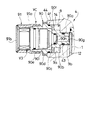
- FIG. 2 is an enlarged view showing a main part of FIG.
- FIG. 3A is an enlarged cross-sectional view showing the damping valve portion of FIG. 2 cut vertically and enlarged.
- FIG. 3B is an enlarged view of a portion B in FIG. 3A.
- FIG. 3C is an enlarged view of a portion C in FIG. 3A.
- FIG. 4 is an enlarged view showing a main part of a shock absorber according to a comparative example of the present invention.
- shock absorber S according to the embodiment of the present invention will be described with reference to the accompanying drawings.
- subjected through some drawings shows the same component or a corresponding component.
- the shock absorber S is held by the cylinder 1, the piston rod 2 that enters and exits the cylinder 1, and the tip of the piston rod 2, and is movable in the cylinder 1 in the axial direction.
- a piston 3 inserted into the cylinder 1, a rod-side chamber 10 and a piston-side chamber 11 that are partitioned in the cylinder 1 by the piston 3 and filled with hydraulic fluid as hydraulic fluid, and a reservoir R that is provided outside the cylinder 1 and stores hydraulic fluid.
- a piston passage L1 that allows only the flow of hydraulic oil from the piston side chamber 11 to the rod side chamber 10, a suction passage L2 that allows only a flow of hydraulic oil from the reservoir R to the piston side chamber 11, and the rod side chamber 10 and the reservoir.
- a discharge passage L3 communicating with R and a damping valve V3 provided in the middle of the discharge passage L3 are provided.
- the shock absorber S is arranged on the outer periphery of the cylinder 1 and forms a cylindrical gap 12 between the shock absorber S and the outer cylinder 4 constituting a double pipe structure.
- a tank 5 in which the reservoir R is formed, and a connecting member RH that connects the outer cylinder 4 and the tank 5 are further provided.
- the discharge passage L3 communicates with the reservoir R through the cylindrical gap 12 and the connection member RH.
- the shock absorber S is used as a rear cushion for suspending a rear wheel in a straddle-type vehicle such as a two-wheeled vehicle or a three-wheeled vehicle.
- the rear cushion includes a shock absorber S, a suspension spring S provided on the outer periphery of the shock absorber S, a pair of upper and lower spring receivers SS1 and SS2 that support end portions of the suspension spring S, and a vehicle height adjustment.
- the suspension spring S is a coil spring, urges the shock absorber S in the extending direction, elastically supports the vehicle body, and absorbs an impact caused by road surface unevenness.
- the jack mechanism J includes a jack chamber 40 filled with incompressible hydraulic oil, a jack piston 41 that can be moved up and down to close the lower opening of the jack chamber 40 and support the upper spring receiver SS1, and a hose JH. And a pump (not shown) connected to the jack chamber 40 and an auxiliary spring 42 for urging the spring receiver SS1 toward the suspension spring S.
- the jack mechanism J supplies and discharges hydraulic oil to and from the jack chamber 40 with a pump, and adjusts the vehicle height by raising and lowering the spring receiver SS1 with the jack piston 41.
- the spring receiver SS1 is also supported by the auxiliary spring 42, it is easy to supply hydraulic oil to the jack chamber 40.
- the configuration of the rear cushion can be changed as appropriate, and the jack mechanism J need not be provided. Further, the shock absorber S according to the present embodiment may be used other than the rear cushion.
- the shock absorber S is formed in a bottomed cylindrical shape and is arranged with the bottom portion 4b facing upward, a cylindrical cylinder 1 provided upright on an axial center portion of the outer cylinder 4, and a cylinder 1
- a base member 6 sandwiched and fixed between the upper end of the outer cylinder 4 and the bottom 4b of the outer cylinder 4, an annular cap 7 screwed into the lower opening end of the outer cylinder 4, and a cap 7
- An annular rod guide 8 that is fixed to the lower opening of the cylinder 1, a piston rod 2 that moves in and out of the cylinder 1 while being supported by the rod guide 8, and a cylinder that is held by the upper end portion (tip portion) of the piston rod 2.
- a piston 3 that is movably inserted in the axial direction, an annular seal ring 80 that blocks between the rod guide 8 and the outer cylinder 4, and an annular dust seal that blocks between the rod guide 8 and the piston rod 2.
- 81 and oil seal 82, and the outside It comprises a tank 5 which is fixed to the vehicle body is disposed on the outside of 4, and the connecting member RH for connecting the tank 5 and the outer cylinder 4, the.
- Attachment members B1 and B2 are fixed to the upper end of the outer cylinder 4 and the lower end of the piston rod 2, respectively.
- the upper mounting member B1 is connected to a vehicle body frame that is a skeleton of the vehicle body.
- the lower mounting member B2 is connected to a swing arm that supports the rear wheel. For this reason, when an impact due to road surface unevenness is input to the rear wheel, the piston rod 2 enters and exits the cylinder 1 and the shock absorber S expands and contracts.
- the shock absorber S is an inverted type in which the cylinder 1 is connected to the vehicle body side and the piston rod 2 is connected to the wheel side. Thereby, the damping valve V3 can be arrange
- the shock absorber S may be an upright type in which the cylinder 1 is connected to the wheel side and the piston rod 2 is connected to the vehicle body side.
- a rod side chamber 10 and a piston side chamber 11 which are partitioned in the cylinder 1 by the piston 3, a cylindrical gap 12 formed on the outer periphery of the cylinder 1, and a bottom 4 b of the outer cylinder 4 are formed.
- a bottom chamber 13 formed between the groove 4c and the base member 6 is formed.
- the rod side chamber 10, the piston side chamber 11, the cylindrical gap 12, and the bottom chamber 13 are filled with hydraulic oil.
- a reservoir R is formed inside a tank 5 that is externally attached to the outer cylinder 4.
- the reservoir R is partitioned into a liquid chamber 51 and an air chamber 52 by a partition member 50 provided in the tank 5.
- the state in which the tank 5 is externally attached to the outer cylinder 4 is a state in which the tank 5 is not accommodated in the outer cylinder 4 or the outer cylinder 4 is not accommodated in the tank 5. That is, the state in which the tank 5 is externally attached to the outer cylinder 4 is a state in which the tank 5 is disposed outside the outer cylinder 4 and the outer cylinder 4 is disposed outside the tank 5.
- the tank 5 is connected to the outer cylinder 4 by a connecting member RH in which a passage (not shown) such as a hose and a pipe line is formed.
- the liquid chamber 51 and the bottom chamber 13 communicate with each other through a passage (not shown) of the connection member RH.
- the outer cylinder 4 and the tank 5 may be integrally formed.
- a joint portion between the outer cylinder 4 and the tank 5 corresponds to the connection member RH, and a passage that connects the liquid chamber 51 and the bottom chamber 13 may be formed in the joint portion.
- the partition member 50 is an elastically deformable bladder.
- the partition member 50 can change the volume ratio while partitioning the liquid chamber 51 and the air chamber 52.
- the liquid chamber 51 is filled with hydraulic oil, and the gas chamber 52 is filled with gas in a compressed state.
- the hydraulic fluid is hydraulic oil, but is not limited to this, and any hydraulic fluid other than the hydraulic fluid may be used.
- the gas is air, but may be an inert gas such as nitrogen.
- the partition member 50 may be other than the bladder as long as the volume ratio of the liquid chamber 51 and the air chamber 52 in the reservoir R can be changed while partitioning the liquid chamber 51 and the air chamber 52.
- the partition member 50 may be a free piston or a bellows.
- the rod side chamber 10 and the piston side chamber 11 communicate with each other through a piston passage L1 formed in the piston 3.
- a check valve V1 is provided in the piston passage L1.
- the piston side chamber 11 communicates with the bottom chamber 13 through a base passage 6 a formed in the base member 6.
- One end of a first bottom passage 4 d formed in the bottom portion 4 b of the outer cylinder 4 communicates with the bottom chamber 13.
- a connection member RH communicating with the liquid chamber 51 of the reservoir R is connected to the other end of the first bottom passage 4d. That is, in the present embodiment, the suction that communicates the piston side chamber 11 and the reservoir R by the base passage 6a, the bottom chamber 13, the first bottom passage 4d, and a passage (not shown) formed in the connection member RH.
- a passage L2 is formed.
- a check valve V2 is provided in the base passage 6a. For this reason, in the suction passage L2, only the flow of hydraulic oil from the reservoir R toward the piston side chamber 11 is allowed, and the flow in the opposite direction is prevented.
- the rod side chamber 10 communicates with the cylindrical gap 12 through a through hole 1 a formed in the lower part of the cylinder 1.
- the cylindrical gap 12 has an attachment hole 9 formed along the radial direction at the boundary portion between the cylindrical portion 4a and the bottom portion 4b of the outer cylinder 4.
- One end of a second bottom passage 4 e formed in the bottom portion 4 b of the outer cylinder 4 communicates with the mounting hole 9.
- the other end of the second bottom passage 4e communicates with the first bottom passage 4d. That is, in this embodiment, the through hole 1a of the cylinder 1, the cylindrical gap 12, the mounting hole 9, the second bottom passage 4e, the first bottom passage 4d, and the connection member RH are not shown.
- a discharge passage L3 that connects the rod side chamber 10 and the reservoir R is constituted by the passage.
- a damping valve V3 that provides resistance to the flow of hydraulic oil passing through the discharge passage L3 is attached to the attachment hole 9.
- the attachment hole 9 is provided in the thick portion 4f formed to protrude radially outward from the upper portion of the outer cylinder 4.
- the attachment hole 9 is formed in the thick part 4f substantially perpendicular to the axial line of the cylindrical part 4a of the outer cylinder 4.
- the mounting hole 9 is provided with a large-diameter insertion hole 9a facing the outer side of the outer cylinder 4 and the center of the insertion hole 9a.
- the mounting hole 9 extends from the insertion hole 9a to the cylindrical gap 12.
- a screw hole 9b penetrating the outer cylinder 4 toward the end.
- the screw hole 9b is formed with a smaller diameter than the insertion hole 9a.
- female screw processing is performed on the cylindrical gap 12 side.
- the damping valve V3 is accommodated in the valve case VC.
- the damping valve V3 constitutes a valve assembly together with the valve case VC and is integrated.
- the valve case VC includes a cylindrical case member 90 connected to the outer cylinder 4 and a bottomed cylindrical cap member 91 that closes the outer opening of the case member 90.
- the case member 90 has a screw portion 90a, a medium diameter portion 90b, a large diameter portion 90c, a flange portion 90d, and a sleeve 90e that are arranged in a coaxial manner in this order from the cylinder 1 side to form a cylindrical shape. Is done.
- the screw portion 90 a is subjected to male screw processing on the outer peripheral surface of the tip portion, and is screwed into the screw hole 9 b of the mounting hole 9.
- the intermediate diameter portion 90b has a larger outer diameter than the screw portion 90a and the screw hole 9b, and a smaller outer diameter than the insertion hole 9a.
- An annular passage 14 through which hydraulic oil can pass between the insertion hole 9a is provided on the outer periphery of the medium diameter portion 90b.
- An annular seal ring 43 is attached to the proximal end portion of the screw portion 90a. For this reason, hydraulic fluid is prevented from passing between the annular passage 14 and the cylindrical gap 12 without passing through the damping valve V3.
- the large diameter portion 90c has a larger outer diameter than the medium diameter portion 90b and is inserted into the insertion hole 9a.
- An annular seal ring 44 is attached to the outer periphery of the large diameter portion 90c. For this reason, it is prevented that the hydraulic fluid of the attachment hole 9 leaks outside.
- a plurality of notches 90f are provided along the circumferential direction at the right end of the large diameter portion 90c in FIG. 2, that is, the end of the large diameter portion 90c on the cylinder 1 side. The notch 90f allows the inside of the case member 90 to communicate with the annular passage 14.
- the flange portion 90d has a larger outer diameter than the large-diameter portion 90c and the insertion hole 9a, and is in contact with the left side surface of the thick portion 4f in the outer cylinder 4 in FIG.
- the outer peripheral surface of the sleeve 90e is subjected to male screw processing.
- the case member 90 has an inflow hole 90g formed from the screw portion 90a to the substantially central portion in the axial direction of the medium diameter portion 90b and opened to the cylindrical gap 12, and communicated with the inflow hole 90g and has a larger diameter than the inflow hole 90g.
- An opening accommodating hole 90i is provided.
- the accommodation hole 90i communicates with the annular passage 14 through the notch 90f.
- the hydraulic oil in the cylindrical gap 12 flows into the inside of the case member 90 from the inflow hole 90g.
- the hydraulic fluid inside the case member 90 is guided to the annular passage 14 from the notch 90f through the damping valve V, and to the reservoir R through the second bottom passage 4e (FIG. 1).
- the cap member 91 that constitutes the valve case VC together with the case member 90 includes a cylindrical portion 91a in which the inner peripheral surface of the tip portion is subjected to female screw processing, and an opening of the cylindrical portion 91a on the side opposite to the cylinder 1, that is, FIG. A bottom portion 91b for closing the middle left opening.
- the bottom portion 91b is fixed by caulking to the left end in FIG. 2 of the cylindrical portion 91a.
- the damping valve V3 accommodated in the valve case VC is an assembly shaft that is provided upright at the tip portion 92a of the case member 90 that fits in the holding hole 90h and the axial center portion of the accommodation hole 90i.
- a valve seat member 92 having a main body 92b, an annular valve housing 93 connected to the assembly shaft 92b of the valve seat member 92, and the valve seat member 92 is held between the valve seat member 92 and the valve housing 93 on the outer periphery of the assembly shaft 92b.
- the valve seat member 92 is formed with a port 92c that communicates the cylindrical gap 12 and the annular passage 14, and a valve seat 92d that surrounds the outlet of the port 92c.
- the leaf spring 95 biases the valve element 94 in the closing direction via the spool 96.
- the leaf spring 95 forms the back pressure chamber 15 together with the valve housing 93 and the spool 96.
- the valve element 94 is urged in the closing direction by the leaf spring 95 and the internal pressure of the back pressure chamber 15.
- the valve body 94 includes a main valve body 94a and a sub valve body 94b.
- the valve opening pressure of the main valve element 94a is set to be larger than the valve opening pressure of the auxiliary valve element 94b. For this reason, the valve element 94 can be opened in two stages in the order of the sub-valve element 94b and the main valve element 94a.
- the seat member 92 is formed with a central hole 92e that passes through the valve seat member 92 in the axial direction and opens to the inside of the valve housing 93.
- the valve housing 93 is formed with a communication passage 93 a that communicates the inside of the valve housing 93 and the back pressure chamber 15.
- the center hole 92e, the inside of the valve housing 93, and the communication passage 93a constitute a part of the pilot passage L30.
- An orifice O is provided in the middle of the center hole 92e. Therefore, the pilot passage L30 reduces the pressure on the upstream side of the port 92c and guides it to the back pressure chamber 15.
- the pilot passage L30 is formed between the pilot valve seat member 97 and a through hole 97a that communicates the inside and outside of the valve housing 93, and between the pilot valve seat member 97 and the pilot valve body 99.
- the pilot valve body 99 and the pilot valve seat member 97 constitute a pilot valve V30.
- the pilot valve body 99 is seated on the valve seat 97b of the pilot valve seat member 97 and the pilot valve V30 is closed, the communication of the pilot passage L30 is blocked.
- the pilot valve body 99 is separated from the valve seat 97b and the pilot valve V30 is opened, the communication of the pilot passage L30 is allowed.
- the pilot valve body 99 is urged by the coil spring 100 in the direction of retreating from the pilot valve seat member 97.
- pilot valve body 99 is separated from the valve seat 97b and abuts against the inner peripheral protrusion portion 98c of the fail valve seat member 98 in a state where the thrust from the solenoid 101 that opposes the biasing force of the coil spring 100 is not received. . Thereby, communication of pilot passage L30 is intercepted.
- the valve opening pressure of the pilot valve V30 can be controlled by the solenoid 101.
- the solenoid 101 is accommodated in the cap member 91 as shown in FIG. 3A.
- the solenoid 101 has an annular solenoid bobbin 101b around which the winding 101a is wound and fixed to the bottom 91b of the cap member 91, and a bottomed cylindrical shape fitted to the inner periphery on the left side in FIG. 3A of the solenoid bobbin 101b.
- a gap is provided between the first fixed iron core 101c and the second fixed iron core 101d.
- a magnetic path is formed so as to pass through the first fixed iron core 101c, the movable iron core 101e, and the second fixed iron core 101d.
- the movable iron core 101e disposed near the first fixed iron core 101c is attracted to the second fixed iron core 101d, and a thrust toward the right side in FIG. 3A acts on the movable iron core 101e.
- a thrust force against the urging force of the coil spring 100 acts on the pilot valve body 99 via the shaft 101f.
- the magnitude of the valve opening pressure in the pilot valve V30 can be adjusted by adjusting the thrust of the solenoid 101 with the magnitude of the current supplied to the solenoid 101.
- the pressure in the pilot passage L30 on the upstream side of the pilot valve V30 becomes equal to the valve opening pressure of the pilot valve V30. Therefore, the pressure of the back pressure chamber 15 to which the pressure of the pilot passage L30 on the upstream side of the pilot valve V30 is guided is also controlled to the valve opening pressure.
- a notch 98d that forms a gap with the pilot valve seat member 97 is formed on the right side of the fail valve seat member 98 in FIG. 3B. Further, the fail valve seat member 98 is formed with a through-hole 98 e penetrating in the radial direction at a fitting portion (not shown) that fits into the valve housing 93.
- the notch 98d faces the inside of the fail valve seat member 98 and constitutes part of the fail passage L31 branched from the pilot passage L30 together with the through hole 98e.
- the fail passage L31 communicates with the annular passage 14 through the notch 98b on the outer periphery of the fail valve seat member 98 and the outer periphery of the spool 96.
- the fail valve body 102 is formed in an annular plate shape, and an inner peripheral portion is sandwiched between the pilot valve seat member 97 and the valve housing 93.
- the fail valve body 102 and the fail valve seat member 98 constitute a fail valve V31.
- the outer periphery of the fail valve body 102 projecting radially outward from the pilot valve seat member 97 is seated on the valve seat 98f of the fail valve seat member 98 and the fail valve V31 is closed, the communication of the fail passage L31 is blocked. .
- the outer periphery of the fail valve body 102 is separated from the valve seat 98f of the fail valve seat member 98 and the fail valve V31 is opened, the communication of the fail passage L31 is allowed.
- the pilot valve body 99 abuts on the inner peripheral projection 98c of the fail valve seat member 98 by the urging force of the coil spring 100, and the pilot passage L30 communicates. Is cut off.
- the outer peripheral portion of the fail valve body 102 is separated from the valve seat 98f.
- the hydraulic oil in the pilot passage L30 can be released to the annular passage 14 through the fail passage L31.
- the configuration of the damping valve V3 is not limited to the above, and can be changed as appropriate.
- the shock absorber S is a uniflow type in which hydraulic oil circulates through the piston side chamber 11, the rod side chamber 10, and the reservoir R in a one-way manner, both when extended and when compressed. Further, the hydraulic oil in the cylinder 1 moves to the reservoir R through the discharge passage L3 during both the expansion and compression. For this reason, the shock absorber S generates a damping force due to the resistance of the damping valve V3 when the hydraulic oil passes through the discharge passage L3.
- the cross-sectional area of the piston rod 2 to be a half of the cross-sectional area of the piston 3, the amount of hydraulic oil discharged from the cylinder 1 can be made equal on both sides of the pressure increase with the same amplitude. . For this reason, if the resistance which damping valve V3 gives to the flow of hydraulic fluid is made the same, the damping force at the time of extension and compression can be set to the same.
- the valve body 94 includes a main valve body 94a and a sub-valve body 94b, and can be opened in two stages.
- the damping coefficient of the damping force generated by the shock absorber S (the ratio of the damping force change amount to the piston speed change amount) is set to a piston speed region where only the sub-valve element 94b is opened, and the piston speed is increased. It can be changed depending on the piston speed region in which the body 94a and the auxiliary valve body 94b open.
- the current supply to the solenoid 101 is cut off, and the pilot valve body 99 is pressed by the coil spring 100 to close the opening on the left side of the fail valve seat member 98 in FIG. 3A.
- the fail valve V31 is opened. Therefore, the hydraulic oil in the pilot passage L30 flows into the annular passage 14 through the fail passage L31 and is guided to the reservoir R. For this reason, the characteristic of the damping force at the time of failure of the shock absorber S can be arbitrarily set in advance by setting the valve opening pressure of the fail valve V31.
- the shock absorber S2 includes a cylinder 1, an intermediate cylinder 900 provided upright on the outer periphery of the cylinder 1, and an outer cylinder 400 provided upright on the outer periphery of the intermediate cylinder 900, and has a triple tube structure.
- a cylindrical gap 120 formed between the intermediate cylinder 900 and the cylinder 1 is used as a part of the discharge passage. Further, a cylindrical gap formed between the intermediate cylinder 900 and the outer cylinder 400 is used as the reservoir R. Holes 901 and 401 penetrating in the thickness direction are formed in the side portions of the intermediate cylinder 900 and the outer cylinder 400, respectively. In addition, cylindrical sleeves 902 and 402 are provided upright along the edges of the respective holes 901 and 401 at the side portions of the intermediate cylinder 900 and the outer cylinder 400, and are attenuated by using both sleeves 902 and 402. A valve V4 is attached.
- the shock absorber S2 has a triple tube structure, the structure of the shock absorber S2 is complicated. Even when the sleeves 902 and 402 are formed by bending a part of a cylindrical member constituting the intermediate cylinder 900 and the outer cylinder 400, the sleeves 902 and 402 are welded to the intermediate cylinder 900 and the outer cylinder 400. Even so, the processing is complicated, and the working efficiency for attaching the damping valve V4 is poor. Furthermore, with such a method of attaching the damping valve V4, it is difficult to attach the damping valve V4 close to one end of the cylinder 1 in the axial direction.
- a suspension spring that elastically supports the vehicle body is provided on the outer periphery of the shock absorber S2, and a jack mechanism is attached to the outer cylinder 400 to provide a spring receiver that supports one end of the suspension spring. Therefore, it may be difficult to adjust the vehicle height by raising and lowering.
- the shock absorber S is inserted into the cylinder 1 so as to be movable in the axial direction while being held by the cylinder 1, the piston rod 2 entering and exiting the cylinder 1, and the tip of the piston rod 2.
- a piston passage L1 that allows only the flow of hydraulic oil toward the rod side chamber 10
- a suction passage L2 that allows only a flow of hydraulic oil from the reservoir R to the piston side chamber 11, and a discharge that communicates the rod side chamber 10 and the reservoir R.
- a passage L3 and a damping valve V3 provided in the middle of the discharge passage L3 are provided.
- the shock absorber S includes an outer cylinder 4 that is disposed on the outer periphery of the cylinder 1 and forms a cylindrical gap 12 between the shock absorber S and a double pipe structure. And a connecting member RH for connecting the outer cylinder 4 and the tank 5 to each other.
- the discharge passage L3 communicates with the reservoir R through the cylindrical gap 12 and the connection member RH.
- the reservoir R is formed in the tank 5 and the shock absorber S set to be a uniflow type has a double tube structure, it has a triple tube structure like the shock absorber S2 according to the comparative example. Compared to the case, the structure of the shock absorber S can be simplified.
- shock absorber S need not be provided with the sleeves 902 and 402 in both the intermediate cylinder 900 and the outer cylinder 400 as in the shock absorber S2, and the sleeve 90e is provided only in the outer cylinder 4 so that the sleeve 90e stands. Good. For this reason, the work efficiency for attaching the damping valve V3 can be improved, and the damping valve V3 can be attached close to one end of the cylinder 1.
- the structure is simple, the working efficiency for attaching the damping valve V3 can be improved, and the damping valve V3 is brought close to one end of the cylinder 1. It can be attached.
- the damping valve V3 includes the valve seat member 92 in which the port 92c constituting a part of the discharge passage L3 is formed, the valve body 94 that opens and closes the port 92c, and the valve body 94 with internal pressure.
- a back pressure chamber 15 that is biased toward the valve seat member 92 side, a pilot passage L30 that reduces the pressure in the cylindrical gap 12 on the upstream side of the port 92c and leads it to the back pressure chamber 15, and a midway in the pilot passage L30
- a pilot valve V30 for controlling the pressure in the back pressure chamber 15 and a solenoid 101 for adjusting the valve opening pressure of the pilot valve V30.
- the damping valve V3 gives to the flow of hydraulic oil passing through the discharge passage L3. Therefore, a desired damping force can be generated in the shock absorber S.
- the configuration of the damping valve V3 is not limited to the above, and can be changed as appropriate.
- the partition member 50 is provided in the tank 5.
- the partition member 50 divides the reservoir R into a liquid chamber 51 filled with hydraulic oil and an air chamber 52 filled with gas while being compressed.
- the partition member 50 is provided so that the volume ratio between the liquid chamber 51 and the air chamber 52 in the reservoir R can be changed.
- the hydraulic oil can be pressurized with the gas sealed in the air chamber 52, so that the damping force generation response can be improved.
- the partition wall member 50 is a bladder, but can be changed as appropriate.
- the partition member 50 may be a free piston or a bellows.
- the shock absorber S includes a valve case VC that houses the damping valve V3.
- the outer cylinder 4 is formed with a screw hole 9b into which the valve case VC is screwed.
- the screw hole 9b can be opened in the outer cylinder 4 by using the tap and the damping valve V3 can be attached, the attaching operation of the damping valve V3 can be greatly simplified.
- the method of attaching the damping valve V3 can be changed as appropriate. For example, even if the outer cylinder 4 is chucked using a dedicated tool, the outer peripheral surface of the thick part 4f of the outer cylinder 4 is subjected to male screw processing with a lathe, and the cap member 91 is directly screwed to the thick part 4f. Good.
Priority Applications (3)
| Application Number | Priority Date | Filing Date | Title |
|---|---|---|---|
| US15/104,459 US20160319897A1 (en) | 2013-12-20 | 2014-12-17 | Shock absorber |
| CN201480069758.9A CN105874238B (zh) | 2013-12-20 | 2014-12-17 | 缓冲器 |
| EP14871062.7A EP3093520A4 (en) | 2013-12-20 | 2014-12-17 | Shock absorber |
Applications Claiming Priority (2)
| Application Number | Priority Date | Filing Date | Title |
|---|---|---|---|
| JP2013263151A JP6154741B2 (ja) | 2013-12-20 | 2013-12-20 | 緩衝器 |
| JP2013-263151 | 2013-12-20 |
Publications (1)
| Publication Number | Publication Date |
|---|---|
| WO2015093535A1 true WO2015093535A1 (ja) | 2015-06-25 |
Family
ID=53402880
Family Applications (1)
| Application Number | Title | Priority Date | Filing Date |
|---|---|---|---|
| PCT/JP2014/083434 WO2015093535A1 (ja) | 2013-12-20 | 2014-12-17 | 緩衝器 |
Country Status (5)
| Country | Link |
|---|---|
| US (1) | US20160319897A1 (zh) |
| EP (1) | EP3093520A4 (zh) |
| JP (1) | JP6154741B2 (zh) |
| CN (1) | CN105874238B (zh) |
| WO (1) | WO2015093535A1 (zh) |
Cited By (1)
| Publication number | Priority date | Publication date | Assignee | Title |
|---|---|---|---|---|
| EP3236105A1 (en) * | 2016-03-31 | 2017-10-25 | Showa Corporation | Shock absorber |
Families Citing this family (21)
| Publication number | Priority date | Publication date | Assignee | Title |
|---|---|---|---|---|
| JP6198601B2 (ja) * | 2013-12-20 | 2017-09-20 | Kyb株式会社 | 緩衝器 |
| DE102015119692A1 (de) * | 2015-11-13 | 2017-05-18 | Thyssenkrupp Ag | Aufnahmeanordnung einer Tragfeder für ein Federbein |
| KR20170089637A (ko) * | 2016-01-27 | 2017-08-04 | 주식회사 만도 | 감쇠력 가변 밸브 조립체 및 이를 포함하는 감쇠력 가변식 쇽업소버 |
| JP6628146B2 (ja) * | 2016-03-30 | 2020-01-08 | 株式会社ショーワ | 緩衝器 |
| JP6826487B2 (ja) * | 2017-04-25 | 2021-02-03 | Kybモーターサイクルサスペンション株式会社 | フロントフォーク |
| CN107444616B (zh) * | 2017-04-25 | 2019-08-06 | 西安航空学院 | 手控高度档位的速度自适应机翼变后掠机构及控制方法 |
| CN107444615B (zh) * | 2017-04-25 | 2019-12-20 | 西安航空学院 | 一种组合弹性自适应机翼变后掠机构及控制方法 |
| USD866408S1 (en) | 2017-08-28 | 2019-11-12 | Qa1 Precision Products, Inc. | Shock absorber |
| USD869259S1 (en) | 2017-08-28 | 2019-12-10 | Qa1 Precision Products, Inc. | Valve component |
| US11105390B2 (en) | 2017-08-28 | 2021-08-31 | Qa1 Precision Products, Inc. | Shock absorber with dry valving |
| USD872837S1 (en) | 2017-08-28 | 2020-01-14 | Qa1 Precision Products, Inc. | Bleed needle |
| US11085502B2 (en) | 2017-08-28 | 2021-08-10 | Qa1 Precision Products, Inc. | Bleed needle for a hydraulic system |
| JP6997592B2 (ja) * | 2017-11-02 | 2022-01-17 | Kyb株式会社 | 緩衝器 |
| JP7212552B2 (ja) * | 2019-03-04 | 2023-01-25 | Kyb株式会社 | 緩衝器 |
| JP2020168898A (ja) * | 2019-04-01 | 2020-10-15 | ヤマハ発動機株式会社 | サスペンションシステム及び車両 |
| DE102019211502B4 (de) * | 2019-08-01 | 2022-03-17 | Audi Ag | Feder-Dämpfer-Einrichtung für ein Fahrzeug, insbesondere für ein Kraftfahrzeug, sowie Fahrzeug mit wenigstens einer solchen Feder-Dämpfer-Einrichtung |
| US11400790B2 (en) * | 2020-01-30 | 2022-08-02 | Schaeffler Technologies AG & Co. KG | Concentric hydraulic ride height actuator for a motor vehicle |
| CN112032238A (zh) * | 2020-09-24 | 2020-12-04 | 福建金汉科技有限公司 | 一种铝合金双调节充气式倒置前减震器 |
| CN113339441A (zh) * | 2021-05-17 | 2021-09-03 | 贵州詹阳动力重工有限公司 | 一种流体介质的缓冲减振机构及车辆 |
| CN117677782A (zh) * | 2021-07-26 | 2024-03-08 | Kyb株式会社 | 带有车辆高度调节功能的缓冲器 |
| CN114542643B (zh) * | 2022-03-24 | 2024-05-03 | 姚海洋 | 可变阻尼力汽车减振器 |
Citations (4)
| Publication number | Priority date | Publication date | Assignee | Title |
|---|---|---|---|---|
| JPS5099007U (zh) * | 1974-01-18 | 1975-08-18 | ||
| JPS6328517U (zh) * | 1986-08-11 | 1988-02-25 | ||
| JPS6421832U (zh) * | 1987-07-30 | 1989-02-03 | ||
| JP2009222136A (ja) | 2008-03-17 | 2009-10-01 | Kayaba Ind Co Ltd | 減衰弁 |
Family Cites Families (13)
| Publication number | Priority date | Publication date | Assignee | Title |
|---|---|---|---|---|
| JPS54138249A (en) * | 1978-04-17 | 1979-10-26 | Kayaba Industry Co Ltd | Shock absorber for twoowheel barrow |
| JPS5981290A (ja) * | 1982-11-01 | 1984-05-10 | 本田技研工業株式会社 | 自動二輪車の制動時姿勢制御装置 |
| JPS59137206A (ja) * | 1983-01-24 | 1984-08-07 | Nissan Motor Co Ltd | サスペンシヨン装置 |
| US4746106A (en) * | 1986-08-15 | 1988-05-24 | Nhk Spring Co., Ltd. | Car suspension system |
| DE4137330C1 (en) * | 1991-11-13 | 1992-11-12 | Boge Ag, 5208 Eitorf, De | Shock absorber for vehicle - includes valve centred by ring and secured in place by screw connection |
| US5957252A (en) * | 1996-08-02 | 1999-09-28 | Berthold; Brian D. | Hydraulic suspension unit |
| US5996746A (en) * | 1997-07-03 | 1999-12-07 | Rockshox, Inc. | Adjustable twin tube shock absorber |
| US6318525B1 (en) * | 1999-05-07 | 2001-11-20 | Marzocchi, S.P.A. | Shock absorber with improved damping |
| US6604751B2 (en) * | 2001-08-30 | 2003-08-12 | Fox Factory, Inc. | Inertia valve shock absorber |
| US7273137B2 (en) * | 2001-08-30 | 2007-09-25 | Fox Factory, Inc. | Inertia valve shock absorber |
| US8403115B2 (en) * | 2008-01-11 | 2013-03-26 | Penske Racing Shocks | Dual rate gas spring shock absorber |
| US9038791B2 (en) * | 2009-01-07 | 2015-05-26 | Fox Factory, Inc. | Compression isolator for a suspension damper |
| JP5961129B2 (ja) * | 2013-03-22 | 2016-08-02 | Kyb株式会社 | 緩衝装置 |
-
2013
- 2013-12-20 JP JP2013263151A patent/JP6154741B2/ja active Active
-
2014
- 2014-12-17 CN CN201480069758.9A patent/CN105874238B/zh not_active Expired - Fee Related
- 2014-12-17 EP EP14871062.7A patent/EP3093520A4/en not_active Withdrawn
- 2014-12-17 US US15/104,459 patent/US20160319897A1/en not_active Abandoned
- 2014-12-17 WO PCT/JP2014/083434 patent/WO2015093535A1/ja active Application Filing
Patent Citations (4)
| Publication number | Priority date | Publication date | Assignee | Title |
|---|---|---|---|---|
| JPS5099007U (zh) * | 1974-01-18 | 1975-08-18 | ||
| JPS6328517U (zh) * | 1986-08-11 | 1988-02-25 | ||
| JPS6421832U (zh) * | 1987-07-30 | 1989-02-03 | ||
| JP2009222136A (ja) | 2008-03-17 | 2009-10-01 | Kayaba Ind Co Ltd | 減衰弁 |
Non-Patent Citations (1)
| Title |
|---|
| See also references of EP3093520A4 * |
Cited By (1)
| Publication number | Priority date | Publication date | Assignee | Title |
|---|---|---|---|---|
| EP3236105A1 (en) * | 2016-03-31 | 2017-10-25 | Showa Corporation | Shock absorber |
Also Published As
| Publication number | Publication date |
|---|---|
| EP3093520A4 (en) | 2017-11-08 |
| EP3093520A1 (en) | 2016-11-16 |
| JP2015117812A (ja) | 2015-06-25 |
| JP6154741B2 (ja) | 2017-06-28 |
| US20160319897A1 (en) | 2016-11-03 |
| CN105874238A (zh) | 2016-08-17 |
| CN105874238B (zh) | 2017-07-28 |
Similar Documents
| Publication | Publication Date | Title |
|---|---|---|
| WO2015093535A1 (ja) | 緩衝器 | |
| US7441638B2 (en) | Front fork | |
| JP5710048B2 (ja) | デジタルバルブを備えたダンパー | |
| CN101802440B (zh) | 半第三管设计 | |
| JP6466905B2 (ja) | 面シールおよび圧力逃がしポートを備える2位置弁 | |
| JP6527760B2 (ja) | 減衰力可変式緩衝器 | |
| EP3002478B1 (en) | Shock absorber with a combination of a fail-safe and check-valve | |
| WO2015093343A1 (ja) | 緩衝器 | |
| JP2016070354A (ja) | 緩衝器 | |
| JP2008089037A (ja) | 減衰力調整式油圧緩衝器 | |
| WO2020179678A1 (ja) | 緩衝器 | |
| WO2016024538A1 (ja) | フロントフォーク | |
| WO2020179680A1 (ja) | 緩衝器 | |
| JP2005351419A (ja) | 油圧緩衝器 | |
| WO2016195008A1 (ja) | 減衰バルブ及び緩衝器 | |
| JP2008089044A (ja) | 減衰力調整式油圧緩衝器 | |
| JP6262977B2 (ja) | 液圧緩衝器 | |
| JP2006132554A (ja) | 緩衝器 | |
| JP7356622B1 (ja) | 緩衝器 | |
| WO2020179679A1 (ja) | 緩衝器 | |
| JP5202426B2 (ja) | 緩衝器 | |
| WO2020179677A1 (ja) | スプール弁および緩衝器 | |
| JP3279127B2 (ja) | セルフポンピング式ショックアブソーバ | |
| TW202338227A (zh) | 後緩衝單元 | |
| JP2018053977A (ja) | 緩衝器 |
Legal Events
| Date | Code | Title | Description |
|---|---|---|---|
| 121 | Ep: the epo has been informed by wipo that ep was designated in this application |
Ref document number: 14871062 Country of ref document: EP Kind code of ref document: A1 |
|
| WWE | Wipo information: entry into national phase |
Ref document number: 15104459 Country of ref document: US |
|
| NENP | Non-entry into the national phase |
Ref country code: DE |
|
| REEP | Request for entry into the european phase |
Ref document number: 2014871062 Country of ref document: EP |
|
| WWE | Wipo information: entry into national phase |
Ref document number: 2014871062 Country of ref document: EP |