WO2015087899A1 - 塗布部材および塗布装置 - Google Patents
塗布部材および塗布装置 Download PDFInfo
- Publication number
- WO2015087899A1 WO2015087899A1 PCT/JP2014/082637 JP2014082637W WO2015087899A1 WO 2015087899 A1 WO2015087899 A1 WO 2015087899A1 JP 2014082637 W JP2014082637 W JP 2014082637W WO 2015087899 A1 WO2015087899 A1 WO 2015087899A1
- Authority
- WO
- WIPO (PCT)
- Prior art keywords
- application needle
- application
- coating
- housing
- holder
- Prior art date
- Legal status (The legal status is an assumption and is not a legal conclusion. Google has not performed a legal analysis and makes no representation as to the accuracy of the status listed.)
- Ceased
Links
Images

Classifications
-
- H—ELECTRICITY
- H05—ELECTRIC TECHNIQUES NOT OTHERWISE PROVIDED FOR
- H05K—PRINTED CIRCUITS; CASINGS OR CONSTRUCTIONAL DETAILS OF ELECTRIC APPARATUS; MANUFACTURE OF ASSEMBLAGES OF ELECTRICAL COMPONENTS
- H05K3/00—Apparatus or processes for manufacturing printed circuits
- H05K3/10—Apparatus or processes for manufacturing printed circuits in which conductive material is applied to the insulating support in such a manner as to form the desired conductive pattern
- H05K3/12—Apparatus or processes for manufacturing printed circuits in which conductive material is applied to the insulating support in such a manner as to form the desired conductive pattern using thick film techniques, e.g. printing techniques to apply the conductive material or similar techniques for applying conductive paste or ink patterns
- H05K3/1241—Apparatus or processes for manufacturing printed circuits in which conductive material is applied to the insulating support in such a manner as to form the desired conductive pattern using thick film techniques, e.g. printing techniques to apply the conductive material or similar techniques for applying conductive paste or ink patterns by ink-jet printing or drawing by dispensing
- H05K3/125—Apparatus or processes for manufacturing printed circuits in which conductive material is applied to the insulating support in such a manner as to form the desired conductive pattern using thick film techniques, e.g. printing techniques to apply the conductive material or similar techniques for applying conductive paste or ink patterns by ink-jet printing or drawing by dispensing by ink-jet printing
-
- B—PERFORMING OPERATIONS; TRANSPORTING
- B05—SPRAYING OR ATOMISING IN GENERAL; APPLYING FLUENT MATERIALS TO SURFACES, IN GENERAL
- B05C—APPARATUS FOR APPLYING FLUENT MATERIALS TO SURFACES, IN GENERAL
- B05C1/00—Apparatus in which liquid or other fluent material is applied to the surface of the work by contact with a member carrying the liquid or other fluent material, e.g. a porous member loaded with a liquid to be applied as a coating
- B05C1/02—Apparatus in which liquid or other fluent material is applied to the surface of the work by contact with a member carrying the liquid or other fluent material, e.g. a porous member loaded with a liquid to be applied as a coating for applying liquid or other fluent material to separate articles
- B05C1/027—Apparatus in which liquid or other fluent material is applied to the surface of the work by contact with a member carrying the liquid or other fluent material, e.g. a porous member loaded with a liquid to be applied as a coating for applying liquid or other fluent material to separate articles only at particular parts of the articles
-
- B—PERFORMING OPERATIONS; TRANSPORTING
- B05—SPRAYING OR ATOMISING IN GENERAL; APPLYING FLUENT MATERIALS TO SURFACES, IN GENERAL
- B05C—APPARATUS FOR APPLYING FLUENT MATERIALS TO SURFACES, IN GENERAL
- B05C1/00—Apparatus in which liquid or other fluent material is applied to the surface of the work by contact with a member carrying the liquid or other fluent material, e.g. a porous member loaded with a liquid to be applied as a coating
- B05C1/02—Apparatus in which liquid or other fluent material is applied to the surface of the work by contact with a member carrying the liquid or other fluent material, e.g. a porous member loaded with a liquid to be applied as a coating for applying liquid or other fluent material to separate articles
-
- B—PERFORMING OPERATIONS; TRANSPORTING
- B05—SPRAYING OR ATOMISING IN GENERAL; APPLYING FLUENT MATERIALS TO SURFACES, IN GENERAL
- B05C—APPARATUS FOR APPLYING FLUENT MATERIALS TO SURFACES, IN GENERAL
- B05C1/00—Apparatus in which liquid or other fluent material is applied to the surface of the work by contact with a member carrying the liquid or other fluent material, e.g. a porous member loaded with a liquid to be applied as a coating
- B05C1/04—Apparatus in which liquid or other fluent material is applied to the surface of the work by contact with a member carrying the liquid or other fluent material, e.g. a porous member loaded with a liquid to be applied as a coating for applying liquid or other fluent material to work of indefinite length
- B05C1/06—Apparatus in which liquid or other fluent material is applied to the surface of the work by contact with a member carrying the liquid or other fluent material, e.g. a porous member loaded with a liquid to be applied as a coating for applying liquid or other fluent material to work of indefinite length by rubbing contact, e.g. by brushes, by pads
-
- H—ELECTRICITY
- H05—ELECTRIC TECHNIQUES NOT OTHERWISE PROVIDED FOR
- H05K—PRINTED CIRCUITS; CASINGS OR CONSTRUCTIONAL DETAILS OF ELECTRIC APPARATUS; MANUFACTURE OF ASSEMBLAGES OF ELECTRICAL COMPONENTS
- H05K2203/00—Indexing scheme relating to apparatus or processes for manufacturing printed circuits covered by H05K3/00
- H05K2203/01—Tools for processing; Objects used during processing
- H05K2203/0104—Tools for processing; Objects used during processing for patterning or coating
- H05K2203/013—Inkjet printing, e.g. for printing insulating material or resist
Definitions
- the present invention relates to an application member and an application device, and more particularly to an application member and an application device for applying liquid material droplets to a material to be processed using an application needle.
- Japanese Patent Application Laid-Open No. 2007-268353 As a method for finely applying a liquid material using an application needle, for example, a method using an application unit as disclosed in Japanese Patent Application Laid-Open No. 2007-268353 has been proposed.
- the coating unit disclosed in Japanese Patent Application Laid-Open No. 2007-268353 is intended to correct fine pattern defects, and can perform fine coating using a material having a wide range of viscosity.
- the application unit there is only one drive shaft of the drive unit (air cylinder) that drives the application needle, and the drive unit and the arm that fixes and supports the application needle are not fixed, and are attached to the drive shaft.
- the arm is supported by a pin protruding from the drive plate.
- the coating material is applied to the substrate by bringing the tip of the coating needle to which the coating material is adhered into contact with the surface to be coated.
- the masses of the application needle fixing plate, the arm, and the movable portion of the linear motion guide member are loaded on the tip of the application needle.
- the present invention has been made to solve the above-described problems, and a main object of the present invention is to provide an application member that can be applied at high speed using a fine application needle and an application apparatus using the same. Is to provide.
- An application member includes an application needle holder including an application needle and a base body that detachably holds the application needle holder.
- the application needle holder includes a housing, a fixing member, and a linear motion member.
- the fixing member is disposed inside the housing, and the application needle is fixed.
- the linear motion member supports the fixed member so as to be movable in one direction inside the housing.
- a coating apparatus includes the above-described coating member and a holding table that holds a processing target material to which a liquid material is coated by a coating needle.
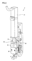
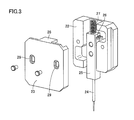
- FIG. 3 is a development view of an application needle holder in the application mechanism shown in FIG. 2. It is a schematic diagram which shows the base body in the application
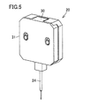
- FIG. 4 is a schematic perspective view of the application needle holder shown in FIG. 3.
- FIG. 4 is a schematic perspective view of the application needle holder shown in FIG. 3.
- a coating apparatus includes a processing chamber, a Y-axis table 2 arranged in the processing chamber, an X-axis table 1, a Z-axis table 3, and coating. It mainly includes a mechanism 4, an observation optical system 6, a CCD camera 7 connected to the observation optical system 6, and a control unit.
- the control unit includes a monitor 9, a control computer 10, and an operation panel 8.
- a Y-axis table 2 is installed on the bottom of the processing chamber.
- This Y-axis table 2 is movable in the Y-axis direction.
- a guide portion is installed on the lower surface of the Y-axis table 2.
- the guide portion is slidably connected to a guide rail installed on the bottom surface of the processing chamber.
- a ball screw is connected to the lower surface of the Y-axis table 2.
- the Y-axis table 2 can be moved along the guide rail (in the Y-axis direction).
- the upper surface of the Y-axis table 2 is a mounting surface on which the substrate 5 that is a processing target material is mounted.
- the X-axis table 1 is installed on the Y-axis table 2.
- the X-axis table 1 is disposed on a structure that is installed so as to straddle the Y-axis table 2 in the X-axis direction.
- a moving body connected to the Z-axis table 3 is installed so as to be movable in the X-axis direction.
- the moving body is movable in the X-axis direction using, for example, a ball screw.
- the X-axis table 1 is fixed to the bottom surface of the processing chamber via the structure. Therefore, the Y-axis table 2 described above is movable in the Y-axis direction with respect to the X-axis table 1.
- the moving body connected to the X-axis table 1 is provided with the Z-axis table 3 as described above.
- An observation optical system 6 and a coating mechanism 4 are connected to the Z-axis table 3.
- the observation optical system 6 is for observing the application position of the substrate 5 to be applied.
- the CCD camera converts the observed image into an electrical signal.
- the Z-axis table 3 holds the observation optical system 6 and the coating mechanism 4 so as to be movable in the Z-axis direction.
- a control computer 10 and an operation panel 8 for controlling these Y-axis table 2, X-axis table 1, Z-axis table 3, observation optical system 6 and coating mechanism 4, and a monitor 9 attached to the control computer are: It is installed outside the processing chamber.
- the monitor 9 displays image data converted by the CCD camera 7 and output data from the control computer 10.
- the operation panel 8 is used for inputting a command to the control computer 10.
- the coating mechanism 4 includes a servo motor 41, a cam 43, a bearing 44 held in contact with the cam surface of the cam 43, a cam connecting plate 45, a movable portion 46, and a coating.
- a movable base 35 (see FIG. 4) for holding the needle holder 20 and an application material container 21 (see FIG. 2) are mainly included.
- the application needle holder 20 is detachable from the movable base 35.
- the servo motor 41 is installed such that the central axis extends in the direction along the Z-axis direction shown in FIG.
- a cam 43 is connected to the rotation shaft of the servo motor 41.
- the cam 43 is rotatable about the central axis of the servo motor 41.
- the cam 43 includes a center portion connected to the rotation shaft of the servo motor 41 and a flange portion connected to one end portion of the center portion.
- the upper surface of the flange portion (surface on the servo motor 41 side) is a cam surface.
- the cam surface is formed in an annular shape along the outer periphery of the center portion, and is formed in a slope shape so that the distance from the bottom surface of the flange portion varies.
- the cam surface has a farthest (thick) upper end flat region that is the farthest from the bottom surface, a lower end flat region that is spaced from the upper end flat region, and the upper end flat region. And a slope portion that smoothly connects the lower end flat region.
- the lower end flat region is a region where the distance from the bottom surface is the shortest (thin thickness).
- the bearing 44 is arranged so as to be in contact with the cam surface of the cam 43.
- a cam coupling plate 45 is connected to the bearing 44.
- the other end opposite to the one end connected to the bearing 44 is fixed to the movable portion 46.
- a movable base 35 is connected to the movable portion 46.
- the application needle holder 20 is installed on the movable base 35.
- the application needle holder 20 includes an application needle 24.
- the application needle 24 is arranged so as to protrude from the application needle holder 20 on the lower surface of the application needle holder 20 (the lower side opposite to the side where the servo motor 41 is located).
- a coating material container 21 is disposed under the coating needle holder 20.
- the application needle 24 is held in the application material container 21 in an inserted state.
- a fixed pin is fixed to the movable part 46. Further, the other fixing pin is fixed to the gantry holding the servo motor 41.
- a spring is installed so as to connect the fixing pins. Due to this spring, the movable portion 46 is in a state of receiving a force directed toward the coating material container 21 side. Further, the bearing 44 is kept pressed against the cam surface of the cam 43 by the force of the spring.
- the movable portion 46 and the movable base 35 are connected to a linear guide installed on a gantry holding the servo motor 41, and are movable along the Z-axis direction.
- the cam 43 is rotated by driving the servo motor 41 to rotate the rotation shaft of the servo motor 41.
- the position of the bearing 44 in contact with the cam surface of the cam 43 in the Z-axis direction varies according to the rotation of the rotation shaft of the servo motor 41.
- the position of the application needle 24 in the Z-axis direction can be changed by moving the movable portion 46 and the movable base 35 in the Z-axis direction in accordance with the position variation of the bearing 44 in the Z-axis direction.
- the application needle holder 20 mainly includes a holder base 22, an application needle fixing plate 25 to which the application needle 24 is fixed, and a holder lid 23. Inside the holder base 22, a recess is formed for accommodating the application needle fixing plate 25 to which the application needle 24 is bonded and fixed. A linear guide 26 is fixed in the recess. The linear guide 26 is arranged to define the moving direction of the application needle fixing plate 25. The application needle fixing plate 25 is held in contact with the linear guide 26.
- a spring 27 as an elastic member is connected to the other end of the application needle fixing plate 25 opposite to the one end where the application needle 24 is fixed.
- the spring 27 is disposed in a state of being sandwiched between the other end of the application needle fixing plate 25 and the spring receiver 28 in the holder lid 23.
- the application needle fixing plate 25 can be pressed to the application needle 24 side. For this reason, when the applicator needle 24 is moved up and down, the position of the applicator needle 24 can be prevented from shifting (fluctuating with respect to the holder base in the vertical direction). Further, when an excessive stress is applied to the application needle 24 when the application needle 24 comes into contact with the surface of the substrate 5 as a processing target material, the spring 27 is elastically deformed to absorb the stress.
- the value of the stress applied to the application needle 24 when the application needle 24 comes into contact with the surface of the substrate 5 is affected by the force from the spring 27, so that the force that the spring 27 applies to the application needle fixing plate 25. Is preferably adjusted to a minimum value necessary for holding the application needle 24 at a position on the substrate side.
- the holder lid 23 has a long hole 29 through which a screw used to fix the holder lid 23 to the holder base 22 is passed.
- the long hole 29 is formed to have a long axis in a direction along the direction in which the linear guide 26 extends (that is, the direction in which the application needle 24 moves) when the holder lid 23 is installed on the holder base 22. .
- the holder lid 23 can be fixed to the holder base 22 after the position of the holder lid 23 with respect to the holder base 22 is changed in the long axis direction of the long hole.
- the holder lid 23 may be fixed to the holder base 22 while measuring the force applied to the tip of the application needle 24 by the spring 27, for example.
- the coating needle holder 20 is detachable from the movable base 35.
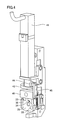
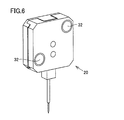
- a plurality of (two in FIG. 6) magnets 32 are arranged on the surface (the surface of the holder base 22) that faces the movable base 35.
- a plurality of (two in FIG. 4) magnets 33 are also arranged on the movable base 35.
- the position of the application needle holder 20 is adjusted when the application needle holder 20 is attracted to the movable base 35 by the magnetic force acting between the magnet 32 and the magnet 33.
- Accurate positioning For example, the reference surface 30 of the application needle holder 20 can be pressed against the reference surface 34 of the movable base 35, and the reference surface 31 of the application needle holder 20 can be pressed against the reference surface 36 of the movable base 35. .
- the position of the magnet 33 of the movable base 35 is changed from the position of the magnet 32 of the application needle holder 20 facing each other to the reference surfaces 34 and 36.
- a magnetic force between the magnets 32 and 33 can apply a suction force toward the reference surfaces 34 and 36 (attraction force in the direction indicated by the arrow in FIG. 4) with respect to the application needle holder 20. it can.
- the application needle holder 20 can be fixed to the movable base 35 with high reproducibility with high positional accuracy.
- the operation of the coating apparatus shown in FIGS. 1 to 6 will be described.
- the X-axis table 1 and the Y-axis table 2 are operated so that the drawing area on the substrate 5 to be coated is directly below the observation optical system 6. Move. Then, the drawing start position is observed and confirmed by the observation optical system 6, and the drawing start position is determined. Using the determined drawing start position as a reference, when the application needle 24 is projected, the Z-axis table 3 is operated to a position where the tip of the application needle 24 contacts the surface of the substrate 5, and the application mechanism 4 is lowered.
- the servo motor 41 is operated to cause the application needle 24 to protrude, and the liquid material adhering to the tip of the application needle 24 is brought into contact with the surface of the substrate 5.
- the substrate 5 is moved from the drawing start position using the X-axis table 1 and the Y-axis table 2 so that the position to be drawn is located immediately below the coating mechanism 4.
- the application needle 24 is projected when the movement is completed, the application mechanism 4 is lowered by the Z-axis table 3 to a position where the tip of the application needle 24 contacts the surface of the substrate 5.
- the servo motor 41 of the application mechanism 4 is driven to apply the liquid material to the substrate 5 by projecting the application needle 24.
- the substrate 5 When coating continuously, the substrate 5 is moved by the X-axis table 1 and the Y-axis table 2 so that the next drawing position is located immediately below the coating mechanism 4, and the servo motor 41 of the coating mechanism 4 is driven. Apply. By repeating this operation, a circuit pattern is drawn on the surface of the substrate 5. After all the coating is completed, the coating mechanism 4 is raised using the Z-axis table 3.
- the relationship between the lower end position of the application needle 24 and the focus position of the observation optical system 6 is stored in advance in the control unit.
- the position where the image is focused by the observation optical system 6 is used as a reference in the Z-axis direction, and the coating mechanism is applied by the Z-axis table 3 until the coating needle 24 comes into contact with the substrate 5 when the coating needle 24 is projected.
- the servo motor 41 of the application mechanism 4 is driven, and the application needle 24 is projected to perform application.
- the focus position is confirmed during the drawing operation as necessary, and the Z axis of the application needle 24 is checked. Apply after correcting the position in the direction.
- the adjustment of the focus position at this time may be a method of automatically adjusting the focus using image processing, or the height position of the surface of the substrate 5 is always detected by using a laser sensor or the like, and the focus is corrected in real time. The method of doing may be used.
- An application member (application mechanism 4) includes an application needle holder 20 including an application needle 24, and a base body that detachably holds the application needle holder 20.
- the application needle holder 20 includes a housing (holder base 22, holder lid 23), a fixing member (application needle fixing plate 25), and a linear motion member (linear guide 26).
- the fixing member (25) is disposed inside the housing (22, 23), and the application needle 24 is fixed thereto.
- the linear motion member (26) supports the fixed member (25) so as to be movable in one direction inside the housings (22, 23).
- the application needle holder 20 includes the application needle 24 and the linear movement member (26) that supports the application needle 24 so as to be movable in one direction, so that the linear movement member (26) is the application needle.
- the application member (4) can be made smaller and lighter than when it is arranged separately from the holder 20. For this reason, even when the moving speed of the application needle 24 is high when the application needle 24 is brought into contact with the surface of the processing target material (the substrate 5 that is the application target material), the load applied to the application needle 24 is reduced. It can be made smaller than before (for example, the mass of the portion supporting the application needle 24 can be reduced to about 10% of the conventional one). Therefore, the diameter of the application needle 24 can be reduced and the application speed can be increased.
- the application needle holder 20 has an elastic member (spring 27) that applies a pressing force to the fixing member (25) in the direction in which the application needle 24 protrudes from the application needle holder 20. Further, it may be included. In this case, since a certain stress can be applied to the application needle 24 by the elastic member (27), the relative movement of the application needle 24 in the application needle holder 20 when the application member (4) is moved. The fluctuation of the position can be suppressed and the position accuracy of the application needle 24 can be increased.
- the housing (22, 23) in the application needle holder 20, includes a first housing portion (holder base 22) and a second housing portion (holder lid 23). May be.
- the fixing member (25) may be connected to the first housing portion (22) via the linear motion member (26).
- the elastic member (27) may be disposed so as to contact a part of the fixing member (25) and a part of the second housing part (23) (spring receiver 28).
- the first housing portion (22) and the second housing portion (23) may be capable of changing the relative positional relationship.
- the second housing part (23) may be formed with a long hole 29 having a long axis along one direction in which the fixing member (25) can move.
- the second housing part (23) may be fixed to the first housing part (22) by a positioning member (screw) passed through the long hole 29.
- a coating apparatus includes a holding table (Y-axis table 2) that holds the coating member (4) and a processing target material (substrate 5) to which a liquid material is coated by the coating needle 24. ). In this way, it is possible to realize a coating apparatus that can perform coating at high speed using the miniaturized coating needle 24.
- the present invention provides a coating member for conducting conductive pattern drawing, correcting open defects in conductive patterns, forming fine circuit patterns such as RFID tags, correcting defects, and applying a conductive adhesive. And particularly advantageously applied to liquid material applicators.
Landscapes
- Engineering & Computer Science (AREA)
- Manufacturing & Machinery (AREA)
- Microelectronics & Electronic Packaging (AREA)
- Coating Apparatus (AREA)
Abstract
微小な塗布針を用いて、高速で塗布可能な塗布部材およびそれを用いた塗布装置を提供する。この発明の実施形態に従った塗布部材(4)は、塗布針(24)を含む塗布針ホルダ(20)と、塗布針ホルダ(20)を着脱可能に保持するベース体とを備える。塗布針ホルダ(20)は、筐体(22、23)と、固定部材(25)と、直動部材(26)とを含む。固定部材(25)は、筐体(22、23)内部に配置され、塗布針(24)が固定されている。直動部材(26)は、筐体(22、23)内部において、固定部材(25)を一方向に移動可能に支持する。
Description
この発明は、塗布部材および塗布装置に関し、より特定的には、塗布針を用いて処理対象材に液体材料の液滴を塗布するための塗布部材および塗布装置に関する。
近年、RFID(Radio Frequency Identification)タグなどの微細な回路を印刷(塗布)方式で形成するプリンテッドエレクトロニクス技術が急速に発展してきている。微細な回路や電極パターンを形成する方式としては、印刷方式、インクジェット方式などが一般的であるが、塗布針を用いた方式も、広範囲の粘度の材料を用いて微細な塗布が可能な点で、近年注目されている。
塗布針を用いて液体材料の微細な塗布を行う方法については、たとえば特開2007-268353号公報に開示されているような塗布ユニットを用いる方法が提案されている。特開2007-268353号公報に開示されている塗布ユニットは、微細パターンの欠陥修正を目的とするもので、広範囲な粘度の材料を用いて微細な塗布を行うことが可能である。
しかし、上記塗布ユニットでは、塗布針を駆動する駆動部(エアシリンダ)の駆動軸は1本のみで、駆動部と塗布針を固定支持するアームとは固着されておらず、駆動軸に取付られた駆動板から突出したピンで上記アームは支持されている。そして、塗布針を処理対象である基板に向けて下降させる場合は、駆動軸を移動させて上記ピンを下降させる(基板側に近づける)。すると、直動案内部材で支持されたアームと、当該アームに接続され塗布針を固定した塗布針固定板が、その自重で基板側へ移動(下降)し、塗布針が下降して基板へ接触する。
また、上記塗布ユニットにおいて、液体材料(塗布材料)を基板へ塗布する際には、塗布材料を付着させた塗布針の先端を塗布対象面に接触させることで、基板へ塗布材料を塗布する。この時、上述の塗布針固定板とアームおよび直動案内部材の可動部の質量が塗布針先端に負荷されることになる。一方、微細なパターンを描画するためには、塗布針先端もその径を細くする必要がある。そして、塗布針先端が細くなるほど、塗布針先端に作用する接触圧力(面圧)が高くなり、塗布時に塗布針先端が破損したり、基板表面(塗布対象面)に塗布針による打痕が発生したりする可能性が高くなる。このため、塗布対象である基板の材質にもよるが、塗布されるパターンのサイズを十分小さくすることが難しい場合がある。
一方で、上述のようなこの接触圧力の課題については、たとえば特開2013-109315号公報に開示されるような機構が提案されている。
特開2013-109315号公報では、上述した塗布針支持部(塗布針固定板とアームおよび直動案内部材の可動部)の質量を、マグネットの反発力や、バネを用いることで、見かけ上軽減させる方法が開示されている。この方法は、低速で塗布針先端を基板の塗布対象面に接触させる場合は効果がある。
しかし、塗布針先端を塗布対象面に接触させる時の当該塗布針の移動速度(接触速度)が速くなると上記効果が薄れ、塗布針先端の破損や、塗布対象である基板へのダメージが発生する。これは、接触速度が速くなると、瞬間的に塗布針支持部の質量が塗布針先端に掛かってしまうからである。そのため、上記特開2013-109315号公報に開示された機構においては、塗布針の移動速度を速めることが難しかった。
ここで、製造効率を高めて製造コストを低減する観点から、RFIDタグなどの微細な回路を短時間で描画することが求められる。そして、このような短時間での描画を実施するためには、塗布針先端サイズの小さい針で、できるだけ塗布速度を速くして塗布する必要がある。しかし、上述の塗布機構では、塗布針先端サイズを小さくし、かつ塗布速度を速めることは難しく、微細なパターンを描画するために長時間を要していた。
この発明は、上記のような課題を解決するためになされたものであり、本願発明の主たる目的は、微小な塗布針を用いて、高速で塗布可能な塗布部材およびそれを用いた塗布装置を提供することである。
この発明に従った塗布部材は、塗布針を含む塗布針ホルダと、塗布針ホルダを着脱可能に保持するベース体とを備える。塗布針ホルダは、筐体と、固定部材と、直動部材とを含む。固定部材は、筐体内部に配置され、塗布針が固定されている。直動部材は、筐体内部において、固定部材を一方向に移動可能に支持する。
この発明に従った塗布装置は、上記塗布部材と、塗布針により液体材料を塗布される処理対象材を保持する保持台とを備える。
本発明によれば、微小な塗布針を用いて、高速で塗布可能な塗布部材およびそれを用いた塗布装置が得られる。
以下、図面に基づいて本発明の実施の形態を説明する。なお、以下の図面において同一または相当する部分には同一の参照番号を付しその説明は繰返さない。
図1を参照して、本実施形態に従った塗布装置を説明する。図1を参照して、本発明の実施形態である塗布装置は、処理室と、当該処理室の内部に配置されたY軸テーブル2と、X軸テーブル1と、Z軸テーブル3と、塗布機構4と、観察光学系6と、当該観察光学系6に接続されたCCDカメラ7と、制御部とを主に備えている。制御部は、モニタ9と、制御用コンピュータ10と、操作パネル8とを含む。
処理室の内部においては、当該処理室の底部上にY軸テーブル2が設置されている。このY軸テーブル2は、Y軸方向に移動可能になっている。具体的には、Y軸テーブル2の下面にガイド部が設置されている。当該ガイド部は、処理室の底面に設置されたガイドレールに摺動可能に接続されている。また、Y軸テーブル2の下面にはボールねじが接続されている。当該ボールねじをモータなどの駆動部材により動作させることにより、Y軸テーブル2はガイドレールに沿って(Y軸方向に)移動可能になっている。また、Y軸テーブル2の上部表面上は、処理対象材である基板5を搭載する搭載面となっている。
Y軸テーブル2上には、X軸テーブル1が設置されている。X軸テーブル1は、Y軸テーブル2をX軸方向に跨ぐように設置された構造体上に配置されている。X軸テーブル1には、Z軸テーブル3が接続された移動体がX軸方向に移動可能に設置されている。移動体は、たとえばボールねじを用いてX軸方向に移動可能となっている。なお、X軸テーブル1は上記構造体を介して処理室の底面に固定されている。そのため、上述したY軸テーブル2は、X軸テーブル1に対してY軸方向に移動可能になっている。
X軸テーブル1に接続された移動体には、上述のようにZ軸テーブル3が設置されている。Z軸テーブル3には、観察光学系6および塗布機構4が接続されている。観察光学系6は塗布対象の基板5の塗布位置を観察するためのものである。CCDカメラは、観察した画像を電気信号に変換する。Z軸テーブル3は、これらの観察光学系6および塗布機構4をZ軸方向に移動可能に保持している。
これらのY軸テーブル2、X軸テーブル1、Z軸テーブル3、観察光学系6および塗布機構4を制御するための制御用コンピュータ10および操作パネル8、さらに制御用コンピュータに付随するモニタ9は、処理室の外部に設置されている。モニタ9は、上述したCCDカメラ7で変換された画像データや、制御用コンピュータ10からの出力データを表示する。操作パネル8は、制御用コンピュータ10への指令を入力するために用いられる。
図2~図6に示すように、塗布機構4は、サーボモータ41、カム43、当該カム43のカム面に接触した状態で保持されている軸受44、カム連結板45、可動部46および塗布針ホルダ20を保持する可動ベース35(図4参照)、塗布材料容器21(図2参照)を主に含む。塗布針ホルダ20は可動ベース35と着脱可能になっている。
塗布機構4において、サーボモータ41は、図1に示したZ軸方向に沿った方向に中心軸が延びるように設置されている。サーボモータ41の回転軸にはカム43が接続されている。カム43は、サーボモータ41の中心軸を中心として回転可能になっている。カム43は、サーボモータ41の回転軸に接続された中心部と、当該中心部の一方端部に接続されたフランジ部とを含む。フランジ部の上部表面(サーボモータ41側の表面)はカム面となっている。このカム面は、中心部の外周に沿って円環状に形成されているとともに、フランジ部の底面からの距離が変動するようにスロープ状に形成されている。具体的には、カム面は底面からの距離が最も遠くなっている(厚みの厚い)上端フラット領域と、この上端フラット領域から間隔を隔てて配置された下端フラット領域と、この上端フラット領域と下端フラット領域との間を滑らかに接続するスロープ部とを含む。下端フラット領域は、底面からの距離が最も近くなっている(厚みの薄い)領域である。
このカム43のカム面に接するように軸受44が配置されている。この軸受44にカム連結板45が接続されている。カム連結板45において、軸受44と接続された一方端部と反対側の他方端部は可動部46に固定されている。この可動部46には、可動ベース35が接続されている。この可動ベース35に塗布針ホルダ20が設置されている。塗布針ホルダ20は塗布針24を含む。塗布針24は、塗布針ホルダ20の下面(サーボモータ41が位置する側と反対側である下側)において塗布針ホルダ20から突出するように配置されている。塗布針ホルダ20下には塗布材料容器21が配置されている。塗布材料容器21に塗布針24は挿入された状態で保持されている。
可動部46には固定ピンが固定されている。また、サーボモータ41を保持している架台には他方の固定ピンが固定されている。この固定ピンの間を繋ぐようにバネが設置されている。このバネにより、可動部46は塗布材料容器21側に向けた力を受けた状態になっている。また、このバネの力によって、軸受44はカム43のカム面に押圧された状態を維持している。
また、可動部46、可動ベース35は、サーボモータ41を保持する架台に設置されたリニアガイドに接続され、Z軸方向に沿って移動可能になっている。
上述した塗布機構4においては、サーボモータ41を駆動することにより当該サーボモータ41の回転軸を回転させてカム43を回転させる。この結果、カム43のカム面に接触している軸受44のZ軸方向における位置がサーボモータ41の回転軸の回転に応じて変動する。そして、この軸受44のZ軸方向での位置変動に応じて、可動部46、可動ベース35がZ軸方向に移動することにより、塗布針24のZ軸方向における位置を変化させることができる。
塗布針ホルダ20は、図3に示すように、ホルダベース22と、塗布針24が固定された塗布針固定板25と、ホルダ蓋23と、を主に含んでいる。ホルダベース22の内部には、塗布針24を接着固定した塗布針固定板25を収容するための凹部が形成されている。また、この凹部内にはリニアガイド26が固定されている。リニアガイド26は、塗布針固定板25の移動方向を規定するために配置されている。塗布針固定板25はリニアガイド26に接触した状態で保持されている。
また、塗布針固定板25において塗布針24が固定された一方端部と反対側の他方端部には、弾性部材としてのバネ27が接続されている。このバネ27は、塗布針固定板25の他方端部とホルダ蓋23におけるバネ受け28との間に挟まれた状態で配置される。このバネ27がある程度圧縮された状態で配置されることで、塗布針固定板25を塗布針24側へ押圧した状態とすることができる。このため、塗布針24を上下移動させたときに、塗布針24の位置がずれる(上下方向にホルダベースに対して変動する)ことを防止できる。さらに、このバネ27は、塗布針24が処理対象材である基板5の表面に接触したときに当該塗布針24に過大な応力が加わった場合に、弾性変形することで当該応力を吸収する。
なお、塗布針24が基板5の表面に接触したときに塗布針24に加わる応力の値は、バネ27からの力に影響されるため、当該バネ27が塗布針固定板25に対して加える力は、塗布針24を基板側の位置に保持するために必要な最低限の値となるように調整されることが好ましい。
ホルダ蓋23には、当該ホルダ蓋23をホルダベース22に固定するために用いるネジを通すための長孔29が形成されている。この長孔29は、ホルダ蓋23をホルダベース22に設置した場合に、リニアガイド26が延びる方向(すなわち塗布針24が移動する方向)に沿った方向に長軸を有するように形成されている。この結果、ホルダベース22に対するホルダ蓋23の位置を、当該長孔の長軸方向において変更したうえで、ホルダ蓋23をホルダベース22に固定することができる。したがって、ホルダ蓋23のホルダベース22に対する位置を変更することで、結果的にバネ受け28と塗布針固定板25の端部との間の距離(バネ27が配置される領域の大きさ)を変更できる。したがって、塗布針ホルダ20を組み立てるときに、たとえばバネ27により塗布針24の先端部に加えられる力を測定しながらホルダ蓋23をホルダベース22に固定してもよい。
図4~図6に示すように、塗布機構4においては、可動ベース35に対して塗布針ホルダ20が着脱可能になっている。具体的には、塗布針ホルダ20においては、可動ベース35と対向することになる表面(ホルダベース22の表面)に複数の(図6では2つの)マグネット32が配置されている。また、可動ベース35にも、複数の(図4では2つの)マグネット33が配置されている。マグネット32とマグネット33とが互いに吸着することにより、塗布針ホルダ20を可動ベース35に設置することができる。そして、マグネット32とマグネット33との位置を調節することにより、マグネット32とマグネット33との間に作用する磁力により塗布針ホルダ20を可動ベース35へ吸着したときに、塗布針ホルダ20の位置を正確に位置決めできる。たとえば、塗布針ホルダ20の基準面30が可動ベース35における基準面34に押圧されるとともに、塗布針ホルダ20の基準面31が可動ベース35の基準面36に押圧された状態とすることができる。このような状態は、たとえば塗布針ホルダ20を可動ベース35に設置したときに、互いに対向する塗布針ホルダ20のマグネット32の位置より、可動ベース35のマグネット33の位置を、基準面34、36寄りに配置しておくことで、マグネット32、33間の磁力により塗布針ホルダ20に対して基準面34、36側へ向かう吸引力(図4の矢印により示す方向の吸引力)を加えることができる。この結果、可動ベース35に対して塗布針ホルダ20を位置精度の高い状態で再現性良く固定できる。
次に、図1~図6に示した塗布装置の動作を説明する。
図1に示した塗布装置において、回路パターンを描画する場合は、まず、塗布対象である基板5における描画する領域を観察光学系6の直下までX軸テーブル1およびY軸テーブル2を動作させて移動させる。そして、観察光学系6で描画開始位置を観察・確認し、描画開始位置を決定する。決定した描画開始位置を基準にして、塗布針24を突出させた時に、塗布針24の先端が基板5の表面に接触する位置までZ軸テーブル3を動作させ、塗布機構4を下降させる。その後、サーボモータ41を動作させ、塗布針24を突出させて、塗布針24の先端に付着した液体材料を基板5の表面に接触させる。具体的には、描画開始位置から、描画するべき位置が塗布機構4の直下に位置するようにX軸テーブル1およびY軸テーブル2を用いて基板5を移動させる。そして、移動が完了した時点で、塗布針24を突出させた時に、塗布針24の先端が基板5の表面に接触する位置まで、Z軸テーブル3で塗布機構4を下降させる。そして、塗布機構4のサーボモータ41を駆動して、塗布針24を突出させて基板5へ液体材料の塗布を行う。連続して塗布する場合は、次の描画位置が塗布機構4の直下に位置するように、X軸テーブル1およびY軸テーブル2で基板5を移動させ、塗布機構4のサーボモータ41を駆動して塗布を行う。この動作を繰り返すことで、基板5表面に回路パターンを描画する。全ての塗布が完了した後、Z軸テーブル3を用いて塗布機構4を上昇させる。
図1に示した塗布装置において、回路パターンを描画する場合は、まず、塗布対象である基板5における描画する領域を観察光学系6の直下までX軸テーブル1およびY軸テーブル2を動作させて移動させる。そして、観察光学系6で描画開始位置を観察・確認し、描画開始位置を決定する。決定した描画開始位置を基準にして、塗布針24を突出させた時に、塗布針24の先端が基板5の表面に接触する位置までZ軸テーブル3を動作させ、塗布機構4を下降させる。その後、サーボモータ41を動作させ、塗布針24を突出させて、塗布針24の先端に付着した液体材料を基板5の表面に接触させる。具体的には、描画開始位置から、描画するべき位置が塗布機構4の直下に位置するようにX軸テーブル1およびY軸テーブル2を用いて基板5を移動させる。そして、移動が完了した時点で、塗布針24を突出させた時に、塗布針24の先端が基板5の表面に接触する位置まで、Z軸テーブル3で塗布機構4を下降させる。そして、塗布機構4のサーボモータ41を駆動して、塗布針24を突出させて基板5へ液体材料の塗布を行う。連続して塗布する場合は、次の描画位置が塗布機構4の直下に位置するように、X軸テーブル1およびY軸テーブル2で基板5を移動させ、塗布機構4のサーボモータ41を駆動して塗布を行う。この動作を繰り返すことで、基板5表面に回路パターンを描画する。全ての塗布が完了した後、Z軸テーブル3を用いて塗布機構4を上昇させる。
なお、塗布針24の下降端位置と観察光学系6のフォーカス位置の関係は予め制御部において記憶されている。描画時には、観察光学系6で画像のフォーカスを合わせた位置をZ軸方向基準にし、塗布針24を突出させた時に、塗布針24が基板5に接触する高さまで、Z軸テーブル3で塗布機構4のZ軸方向位置を移動させてから、塗布機構4のサーボモータ41を駆動して、塗布針24を突出させて塗布を行う。
また、描画する回路パターンの面積が広く、描画途中での基板5の基板面高さの変化が大きい場合は、必要に応じて描画動作の途中でフォーカス位置を確認し、塗布針24のZ軸方向での位置を修正してから塗布を行う。この時のフォーカス位置の調整は、画像処理を用いて自動でフォーカス調整する方法でも良いし、レーザセンサ等を用いて、常に基板5の表面の高さ位置を検出し、リアルタイムでフォーカスに関して補正を行なう方法でも良い。
ここで、上述した実施の形態と一部重複する部分もあるが、本発明の特徴的な構成を列挙する。
(1) この発明の実施形態に従った塗布部材(塗布機構4)は、塗布針24を含む塗布針ホルダ20と、塗布針ホルダ20を着脱可能に保持するベース体とを備える。塗布針ホルダ20は、筐体(ホルダベース22、ホルダ蓋23)と、固定部材(塗布針固定板25)と、直動部材(リニアガイド26)とを含む。固定部材(25)は、筐体(22、23)内部に配置され、塗布針24が固定されている。直動部材(26)は、筐体(22、23)内部において、固定部材(25)を一方向に移動可能に支持する。
このようにすれば、塗布針ホルダ20が塗布針24と当該塗布針24を一方向に移動可能に支持する直動部材(26)とを含むことにより、当該直動部材(26)が塗布針ホルダ20と別体で配置される場合より塗布部材(4)を小型化、軽量化できる。このため、塗布針24を処理対象材(塗布対象材である基板5)の表面に接触させるときに塗布針24の移動速度が速い場合であっても、当該塗布針24に付加される荷重を従来より小さくできる(たとえば、塗布針24を支持する部分の質量を従来の10%程度にまで軽減できる)。したがって、塗布針24の小径化および塗布速度の高速化が可能となる。
(2) 上記塗布部材(4)において、塗布針ホルダ20は、塗布針ホルダ20から塗布針24が突出する方向に向けて、固定部材(25)に押圧力を加える弾性部材(バネ27)をさらに含んでいてもよい。この場合、弾性部材(27)により塗布針24に対して一定の応力を加えておくことができるので、塗布部材(4)を移動させるときに、塗布針ホルダ20における塗布針24の相対的な位置が変動することを抑制し、塗布針24の位置精度を高めることができる。
(3) 上記塗布部材(4)では、塗布針ホルダ20において、筐体(22、23)は第1筐体部分(ホルダベース22)と第2筐体部分(ホルダ蓋23)とを含んでいてもよい。固定部材(25)は第1筐体部分(22)に直動部材(26)を介して接続されていてもよい。弾性部材(27)は、固定部材(25)の一部と第2筐体部分(23)の一部(バネ受け28)とにそれぞれ接触するように配置されていてもよい。第1筐体部分(22)と第2筐体部分(23)とは、相対的な位置関係を変更可能になっていてもよい。
また、上記塗布部材(4)において、第2筐体部分(23)には、固定部材(25)が移動可能な一方向に沿った長軸を有する長孔29が形成されていてもよい。第2筐体部分(23)は、長孔29を通した位置決め部材(ネジ)により第1筐体部分(22)に固定されていてもよい。
この場合、第1筐体部分(22)と第2筐体部分(23)との相対的な位置関係を変更することにより、固定部材(25)の一部(塗布針固定板25の上端部)と第2筐体部分(23)の一部(バネ受け28)との間の距離(つまり弾性部材(27)が配置されるべき空間の大きさ)を任意に変更できる。したがって、当該距離を調整することで、弾性部材(27)が固定部材(25)の一部と第2筐体部分(23)の一部(28)との間に配置されたときに当該弾性部材(27)が圧縮される程度(つまり固定部材(25)が弾性部材(27)より受ける応力の大きさ)を調整できる。
(4) この発明の実施形態に従った塗布装置は、上記塗布部材(4)と、塗布針24により液体材料を塗布される処理対象材(基板5)を保持する保持台(Y軸テーブル2)とを備える。このようにすれば、小型化した塗布針24を用いて高速に塗布を行なうことが可能な塗布装置を実現できる。
今回開示された実施の形態はすべての点で例示であって制限的なものではないと考えられるべきである。本発明の範囲は上記した説明ではなくて請求の範囲によって示され、請求の範囲と均等の意味および範囲内でのすべての変更が含まれることが意図される。
この発明は、導電性のパターン描画や、導電性パターンのオープン欠陥の修正、さらにはRFIDタグなどの微細な回路パターンの形成や欠陥修正、導電性接着剤の塗布などを実施するための塗布部材および液体材料塗布装置に特に有利に適用される。
1 X軸テーブル、2 Y軸テーブル、3 Z軸テーブル、4 塗布機構、5 基板、6 観察光学系、7 CCDカメラ、8 操作パネル、9 モニタ、10 制御用コンピュータ、20 塗布針ホルダ、21 塗布材料容器、22 ホルダベース、23 ホルダ蓋、24 塗布針、25 塗布針固定板、26 リニアガイド、27 バネ、29 長孔、30,31,34,36 基準面、32,33 マグネット、35 可動ベース、41 サーボモータ、43 カム、44 軸受、45 カム連結板、46 可動部。
Claims (5)
- 塗布針を含む塗布針ホルダと、
前記塗布針ホルダを着脱可能に保持するベース体とを備え、
前記塗布針ホルダは、
筐体と、
前記筐体内部に配置され、前記塗布針が固定された固定部材と、
前記筐体内部において、前記固定部材を一方向に移動可能に支持する直動部材とを含む、塗布部材。 - 前記塗布針ホルダは、前記塗布針ホルダから前記塗布針が突出する方向に向けて、前記固定部材に押圧力を加える弾性部材をさらに含む、請求項1に記載の塗布部材。
- 前記塗布針ホルダにおいて、前記筐体は第1筐体部分と第2筐体部分とを含み、
前記固定部材は前記第1筐体部分に前記直動部材を介して接続され、
前記弾性部材は、前記固定部材の一部と前記第2筐体部分の一部とにそれぞれ接触するように配置され、
前記第1筐体部分と前記第2筐体部分とは、相対的な位置関係を変更可能になっている、請求項2に記載の塗布部材。 - 前記第2筐体部分には、前記一方向に沿った長軸を有する長孔が形成され、
前記第2筐体部分は、前記長孔を通した位置決め部材により前記第1筐体部分に固定されている、請求項3に記載の塗布部材。 - 請求項1に記載の塗布部材と、
前記塗布針により液体材料を塗布される処理対象材を保持する保持台とを備える、塗布装置。
Priority Applications (1)
| Application Number | Priority Date | Filing Date | Title |
|---|---|---|---|
| CN201480067690.0A CN105813765B (zh) | 2013-12-13 | 2014-12-10 | 涂布构件及涂布装置 |
Applications Claiming Priority (2)
| Application Number | Priority Date | Filing Date | Title |
|---|---|---|---|
| JP2013-258189 | 2013-12-13 | ||
| JP2013258189A JP6381902B2 (ja) | 2013-12-13 | 2013-12-13 | 塗布針ホルダ |
Publications (1)
| Publication Number | Publication Date |
|---|---|
| WO2015087899A1 true WO2015087899A1 (ja) | 2015-06-18 |
Family
ID=53371201
Family Applications (1)
| Application Number | Title | Priority Date | Filing Date |
|---|---|---|---|
| PCT/JP2014/082637 Ceased WO2015087899A1 (ja) | 2013-12-13 | 2014-12-10 | 塗布部材および塗布装置 |
Country Status (3)
| Country | Link |
|---|---|
| JP (1) | JP6381902B2 (ja) |
| CN (1) | CN105813765B (ja) |
| WO (1) | WO2015087899A1 (ja) |
Cited By (2)
| Publication number | Priority date | Publication date | Assignee | Title |
|---|---|---|---|---|
| US11478813B2 (en) * | 2017-02-27 | 2022-10-25 | Ntn Corporation | Liquid application unit with application needle for applying liquid material on target, and liquid application apparatus including liquid application unit |
| WO2023072624A1 (de) * | 2021-10-28 | 2023-05-04 | Focke & Co. (Gmbh & Co. Kg) | VORRICHTUNG ZUM AUFTRAGEN VON VORZUGSWEISE ERWÄRMTEM KLEBSTOFF BZW. (HEIß-)LEIM |
Families Citing this family (5)
| Publication number | Priority date | Publication date | Assignee | Title |
|---|---|---|---|---|
| JP6835506B2 (ja) * | 2016-09-01 | 2021-02-24 | Ntn株式会社 | 液体塗布ユニットおよび液体塗布装置 |
| JP6461260B1 (ja) | 2017-08-02 | 2019-01-30 | Ntn株式会社 | 塗布機構及び塗布装置 |
| JP7164997B2 (ja) * | 2018-08-31 | 2022-11-02 | Ntn株式会社 | 塗布針部材、塗布針部材アセンブリ、塗布部材および塗布装置 |
| JP7621134B2 (ja) | 2021-02-25 | 2025-01-24 | Ntn株式会社 | 塗布機構及び塗布装置 |
| JP7681421B2 (ja) * | 2021-04-08 | 2025-05-22 | サンスター技研株式会社 | 塗工装置 |
Citations (3)
| Publication number | Priority date | Publication date | Assignee | Title |
|---|---|---|---|---|
| JPH0253162U (ja) * | 1988-10-12 | 1990-04-17 | ||
| JP2008178775A (ja) * | 2007-01-23 | 2008-08-07 | Shibaura Mechatronics Corp | 流体塗布装置および塗布距離測定方法 |
| JP2013081884A (ja) * | 2011-10-07 | 2013-05-09 | Musashi Eng Co Ltd | 液体材料の吐出装置および方法 |
Family Cites Families (4)
| Publication number | Priority date | Publication date | Assignee | Title |
|---|---|---|---|---|
| KR19990044451A (ko) * | 1995-09-07 | 1999-06-25 | 아사무라 다까시 | 프리코트 강판의 절단면 도장방법 및 도장장치 |
| JP4125031B2 (ja) * | 2002-04-11 | 2008-07-23 | 株式会社リコー | 定着装置及びその定着装置を有する画像形成装置 |
| JP4767708B2 (ja) * | 2005-03-28 | 2011-09-07 | Ntn株式会社 | 塗布ユニットおよびパターン修正装置 |
| JP2008073637A (ja) * | 2006-09-22 | 2008-04-03 | Ntn Corp | 塗布針洗浄装置 |
-
2013
- 2013-12-13 JP JP2013258189A patent/JP6381902B2/ja active Active
-
2014
- 2014-12-10 CN CN201480067690.0A patent/CN105813765B/zh active Active
- 2014-12-10 WO PCT/JP2014/082637 patent/WO2015087899A1/ja not_active Ceased
Patent Citations (3)
| Publication number | Priority date | Publication date | Assignee | Title |
|---|---|---|---|---|
| JPH0253162U (ja) * | 1988-10-12 | 1990-04-17 | ||
| JP2008178775A (ja) * | 2007-01-23 | 2008-08-07 | Shibaura Mechatronics Corp | 流体塗布装置および塗布距離測定方法 |
| JP2013081884A (ja) * | 2011-10-07 | 2013-05-09 | Musashi Eng Co Ltd | 液体材料の吐出装置および方法 |
Cited By (2)
| Publication number | Priority date | Publication date | Assignee | Title |
|---|---|---|---|---|
| US11478813B2 (en) * | 2017-02-27 | 2022-10-25 | Ntn Corporation | Liquid application unit with application needle for applying liquid material on target, and liquid application apparatus including liquid application unit |
| WO2023072624A1 (de) * | 2021-10-28 | 2023-05-04 | Focke & Co. (Gmbh & Co. Kg) | VORRICHTUNG ZUM AUFTRAGEN VON VORZUGSWEISE ERWÄRMTEM KLEBSTOFF BZW. (HEIß-)LEIM |
Also Published As
| Publication number | Publication date |
|---|---|
| CN105813765A (zh) | 2016-07-27 |
| JP6381902B2 (ja) | 2018-08-29 |
| CN105813765B (zh) | 2018-11-16 |
| JP2015112577A (ja) | 2015-06-22 |
Similar Documents
| Publication | Publication Date | Title |
|---|---|---|
| JP6381902B2 (ja) | 塗布針ホルダ | |
| JP6411735B2 (ja) | 塗布部材、塗布装置および塗布方法 | |
| CN101067709B (zh) | 图像抖动校正设备和方法 | |
| WO2017090381A1 (ja) | 塗布ユニット、塗布装置、被塗布対象物の製造方法および基板の製造方法 | |
| CN107614122B (zh) | 液体涂布单元及液体涂布装置 | |
| WO2018155589A1 (ja) | 液体塗布ユニットおよび液体塗布装置 | |
| JP2018020325A (ja) | 塗布部材、塗布装置および塗布方法 | |
| WO2016093007A1 (ja) | 塗布機構および塗布装置 | |
| JP6560108B2 (ja) | 塗布ユニット、塗布装置、被塗布対象物の製造方法および基板の製造方法 | |
| US10751747B2 (en) | Application mechanism, application apparatus, method for manufacturing object to which application material is applied, and method for manufacturing substrate | |
| JP6794187B2 (ja) | 液体塗布ユニットおよび液体塗布装置 | |
| CN115348384A (zh) | 照相机装置及电子设备 | |
| JP6716654B2 (ja) | 塗布部材、塗布装置および塗布方法 | |
| JP2017094287A (ja) | 塗布ユニット、塗布装置、被塗布対象物の製造方法および基板の製造方法 | |
| JP2024121598A (ja) | 塗布針および塗布装置 | |
| JP2018130694A (ja) | 液体塗布ユニットおよび液体塗布装置 | |
| CN116847933A (zh) | 涂布机构和涂布装置 | |
| WO2016204152A1 (ja) | 塗布装置 |
Legal Events
| Date | Code | Title | Description |
|---|---|---|---|
| 121 | Ep: the epo has been informed by wipo that ep was designated in this application |
Ref document number: 14868987 Country of ref document: EP Kind code of ref document: A1 |
|
| NENP | Non-entry into the national phase |
Ref country code: DE |
|
| 122 | Ep: pct application non-entry in european phase |
Ref document number: 14868987 Country of ref document: EP Kind code of ref document: A1 |