WO2015083235A1 - 自動分析装置 - Google Patents
自動分析装置 Download PDFInfo
- Publication number
- WO2015083235A1 WO2015083235A1 PCT/JP2013/082474 JP2013082474W WO2015083235A1 WO 2015083235 A1 WO2015083235 A1 WO 2015083235A1 JP 2013082474 W JP2013082474 W JP 2013082474W WO 2015083235 A1 WO2015083235 A1 WO 2015083235A1
- Authority
- WO
- WIPO (PCT)
- Prior art keywords
- information
- unit
- user
- storage unit
- analysis
- Prior art date
- Legal status (The legal status is an assumption and is not a legal conclusion. Google has not performed a legal analysis and makes no representation as to the accuracy of the status listed.)
- Ceased
Links
Images



Classifications
-
- G—PHYSICS
- G01—MEASURING; TESTING
- G01N—INVESTIGATING OR ANALYSING MATERIALS BY DETERMINING THEIR CHEMICAL OR PHYSICAL PROPERTIES
- G01N35/00—Automatic analysis not limited to methods or materials provided for in any single one of groups G01N1/00 - G01N33/00; Handling materials therefor
- G01N35/00584—Control arrangements for automatic analysers
- G01N35/00722—Communications; Identification
- G01N35/00732—Identification of carriers, materials or components in automatic analysers
-
- G—PHYSICS
- G01—MEASURING; TESTING
- G01N—INVESTIGATING OR ANALYSING MATERIALS BY DETERMINING THEIR CHEMICAL OR PHYSICAL PROPERTIES
- G01N35/00—Automatic analysis not limited to methods or materials provided for in any single one of groups G01N1/00 - G01N33/00; Handling materials therefor
- G01N35/00584—Control arrangements for automatic analysers
- G01N35/00722—Communications; Identification
- G01N35/00732—Identification of carriers, materials or components in automatic analysers
- G01N2035/00742—Type of codes
- G01N2035/00782—Type of codes reprogrammmable code
-
- G—PHYSICS
- G01—MEASURING; TESTING
- G01N—INVESTIGATING OR ANALYSING MATERIALS BY DETERMINING THEIR CHEMICAL OR PHYSICAL PROPERTIES
- G01N35/00—Automatic analysis not limited to methods or materials provided for in any single one of groups G01N1/00 - G01N33/00; Handling materials therefor
- G01N35/00584—Control arrangements for automatic analysers
- G01N35/00722—Communications; Identification
- G01N35/00732—Identification of carriers, materials or components in automatic analysers
- G01N2035/00821—Identification of carriers, materials or components in automatic analysers nature of coded information
- G01N2035/00831—Identification of carriers, materials or components in automatic analysers nature of coded information identification of the sample, e.g. patient identity, place of sampling
-
- G—PHYSICS
- G01—MEASURING; TESTING
- G01N—INVESTIGATING OR ANALYSING MATERIALS BY DETERMINING THEIR CHEMICAL OR PHYSICAL PROPERTIES
- G01N35/00—Automatic analysis not limited to methods or materials provided for in any single one of groups G01N1/00 - G01N33/00; Handling materials therefor
- G01N35/00584—Control arrangements for automatic analysers
- G01N35/00722—Communications; Identification
- G01N2035/00891—Displaying information to the operator
Definitions
- the present invention relates to an automatic analyzer that automatically executes an analysis item designated by a user for an installed sample.
- An automatic analyzer that automatically analyzes samples, when a user places a container that contains a sample in a specified position, collects a specified amount of sample from that container, dispenses it into the analysis container, and performs the specified analysis. Depending on the item, a predetermined amount of a reagent is added to the analysis container, and the absorbance or the like is measured to determine the concentration of the component contained in the sample (see, for example, Patent Document 1).
- Such an automatic analyzer stores information on material (hereinafter, material information) and analysis item information.
- the calibration sample is a sample used for derivation of a calibration coefficient for converting a measured value such as absorbance of the sample into a quantitative value (concentration), and is a sample whose concentration is known for a measurement item.
- the quality control sample is a sample for evaluating the measurement accuracy of the device by taking the difference between the quantitative value obtained by measuring this quality control sample and the target value set for this quality control sample. is there.
- the material information includes information such as the material code, material name, lot, and expiration date for identifying each material (a known concentration value for each analysis item for calibration samples, and a target value for quality control samples). Included).
- the analysis item information includes information such as the item code and item name that identifies each analysis item, the target sample type, and the unit of quantitative value, as well as the type (material code) and quantity of material used in each analysis item. Information is also included.
- material information and analysis item information described above vary depending on the material installed in the device. For this reason, material information and analysis item information are created by a material manufacturer, and a recording medium such as a CD (compact disk) storing the information is provided to the user and introduced into the apparatus via the recording medium.
- a recording medium such as a CD (compact disk) storing the information is provided to the user and introduced into the apparatus via the recording medium.
- the material manufacturer guarantees a certain level of accuracy in the analysis results using the material on the assumption that material information and analysis item information corresponding to the provided material will be used. Therefore, for the analysis item selected from the analysis items prepared by the material manufacturer, the user can obtain the accuracy guaranteed by the material manufacturer for the analysis result of the analysis item.
- Automatic analyzers often have a function to edit analysis item information and material information so that user-specific analysis items can be executed separately from analysis items prepared by material manufacturers. If the user accidentally changes the analysis item information prepared by the material manufacturer and tries to create a new analysis item that is different from the existing analysis item, the correct analysis of the analysis item will be performed when the analysis item is specified. Is not executed, and although the analysis item is prepared by the material manufacturer, the analysis accuracy guaranteed by the material manufacturer cannot be obtained.
- an object of the present invention is to prevent analysis item information and material information stored in an automatic analyzer from being erroneously altered.
- the automatic analyzer includes a material holding unit, an analysis operation unit, an information storage unit, an information storage unit, an information editing unit, and an information rewrite management unit.
- the material holding unit holds a plurality of materials including a reagent and a calibration sample.
- the analysis operation unit executes the sample analysis operation using the material held in the material holding unit.
- the information storage unit stores material information that is information related to the material and analysis item information that is information related to the analysis item of the sample.
- the information storage means stores externally input material information and analysis item information in the information storage unit, and for each information stored in the information storage unit, the information is user-created information created by the user Adds an identifier indicating that it is user-created information to the information, and if it is unique information that is not user-created information, adds an identifier indicating that the information is unique information to the information storage unit. It has become.
- the control means is configured to control the analysis operation unit so that the analysis item specified by the user is executed based on the information in the information storage unit.
- the information editing means causes the user to specify any of the information stored in the information storage unit, executes an information editing mode for editing the information specified by the user, and rewrites the existing information with the edited information. It is configured as follows. Based on the identifier added to the information specified by the user, the information rewrite management means permits rewriting when the information is user-created information and rewrites when the information is unique information in the information editing mode. Is configured to ban.
- the automatic analysis device of the present invention distinguishes material information and analysis item information between user-created information created by the user and unique information that is not user-created information, and adds an identifier for distinguishing between the information storage unit When the user edits the information stored in the information storage unit, only the user-created information is permitted to be edited.
- the specific information is defined as information that is not user-created information, but the information that is not user-created information is an analysis item that is prepared in advance in the automatic analyzer (information storage unit) by the manufacturer of the automatic analyzer
- material information provided by a material manufacturer and analysis item information related to the material information.
- the analysis accuracy guaranteed by the manufacturer can be obtained.
- the unique information is altered, the analysis accuracy guaranteed by the manufacturer may not be obtained.
- the editing of the unique information by the user is prohibited, and only the user-created information is allowed to be edited.
- the material information and analysis item information stored in the information storage unit include an identification code for identifying each information, and the material information and analysis item information are managed by the identification code in the apparatus.
- the information storage means is preferably configured to add an identifier to the identification code of each piece of information stored in the information storage unit. If an identifier indicating whether the information is unique information or user-created information is added to the identification code used to manage each information, whether each information is unique information or user-created information Is easy to distinguish.
- the information display unit for displaying information to the user and the information stored in the information storage unit when the information editing mode is executed are added to the respective information. It is preferable to include information display means for displaying the identifier being recognized by the user. This makes it easy to recognize whether the information displayed on the information display section is user-created information or unique information, making it easy to edit information that cannot be edited and information that cannot be edited. Can be determined.
- the information display means is preferably configured to display the fact on the information display unit. Then, even if the user erroneously specifies the unique information as the information to be edited, the user can immediately recognize that the information is the unique information, and the efficiency of the information editing work is improved.
- the information storage means adds information indicating that the material information and the analysis item information are unique information to information input from the outside via the storage medium, and information It is comprised so that it may store in a memory
- material information about the material and analysis item information related to the material are created by the material manufacturer and provided to the user in a state of being stored in a storage medium such as a CD (compact disc).
- material information and analysis item information are input to the apparatus via the storage medium. Therefore, since the information input to the device via the storage medium is unique information, it is possible to prevent alteration of the information provided by the material manufacturer by adding an identifier indicating that the information is unique information. be able to.
- An ID input means for inputting an operator ID for specifying the authority of the operator is further provided, and the information rewrite management means is an ID associated with an identifier attached to the unique information by the operator ID input by the operator.
- the information rewrite management means is an ID associated with an identifier attached to the unique information by the operator ID input by the operator.
- the specific information can be edited by an authorized person.
- the information rewriting management means is configured to recognize new information created by duplicating existing unique information as user created information. As a result, if the user duplicates the existing unique information, the duplicate information is recognized as user-created information and can be edited, so new analysis items etc. should be created using the existing unique information. Will be able to.
- the automatic analysis device includes a plurality of analysis devices each including a material holding unit and an analysis operation unit, and one arithmetic process that is connected to all of the analysis devices and manages each analysis device in an integrated manner.
- the present invention can also be applied to an automatic analyzer configured with a device.
- the information storage unit, the information storage means, the control means, the information editing means, and the information rewrite management means are provided in the arithmetic processing unit.
- the automatic analyzer distinguishes material information and analysis item information between user-created information created by the user and unique information that is not user-created information, and adds an identifier for distinguishing each of the information and stores it in the information storage unit
- the user edits the information stored in the information storage unit only the user-created information is allowed to be edited. Can be prevented.
- This automatic analyzer comprises an analyzer main body 1 and a processing unit 2.
- the arithmetic processing unit 2 is connected to the analyzer main body 1 and performs various arithmetic processes based on operation management of the analyzer main body 1 and data obtained by the analyzer main body 1.
- the analysis apparatus main body 1 includes an analysis operation unit 3, a transport mechanism 4, and a control unit 50 that controls the operations thereof.
- the transport mechanism 4 is a belt conveyor that places and transports the sample rack 6.
- a plurality of sample containers 8 are held in the sample rack 6 that is transported by the transport mechanism 4, and a sample to be analyzed by the analysis operation unit 3 is accommodated in the sample container 8.
- a rack introduction mechanism 10 for transporting the sample rack 6 between the analysis operation unit 3 and the transport mechanism 4 is provided.
- the rack introduction mechanism 10 is configured to hold the sample rack 6 at a predetermined position on the transport mechanism 4 and transport the sample rack 6 to a predetermined sampling position, and return the held sample rack 6 to the transport mechanism 4 when sampling is completed. .
- the analysis operation unit 3 includes a sampling arm 12, a reaction container transport mechanism 14, a transport arm 18, a measurement unit 20, a material supply arm 22, and a material holding unit 24.
- the sampling arm 12 is an arm that rotates around the proximal end, and has a sampling needle on the distal end side.
- the rack introducing mechanism 10 can place the sample container 8 on the needle track of the sampling arm 12.
- the sampling arm 12 inserts the tip of the needle into the sample container 8 arranged on the needle trajectory, and the sample is sucked and collected from the needle tip.
- the reaction container transport mechanism 14 holds a plurality of reaction containers 16 on the same circumference, and conveys the reaction container 16 to a predetermined position by rotating in the circumferential direction.
- the reaction vessel 16 is a vessel that accommodates and reacts the sample collected by the needle of the sampling arm 12.
- the reaction container transport mechanism 14 can place the reaction container 16 at a position on the orbit of the needle of the sampling arm 12, and the sample collected from the sample container 8 is dispensed into the reaction container 16 by the needle of the sampling arm 12. .
- the transfer arm 18 is an arm that rotates around the base end, and includes a holding portion that holds the reaction vessel 16 on the tip side.
- the reaction container transport mechanism 14 can place the reaction container 16 containing the sample at a position on the track of the holding portion of the transport arm 18, and the transport arm 18 is transported by the reaction container transport mechanism 14. And can be arranged in any of the measurement units 20 provided at a plurality of locations on the track of the holding unit.
- the material holding unit 24 holds a plurality of material containers 26 on the same circumference and conveys the material containers 26 to a predetermined position by rotating in the circumferential direction.
- the material container 26 contains materials such as reagents and calibration samples.
- the material supply arm 22 is an arm that rotates so as to draw a concentric circle with the transfer arm 18, and includes a needle for collecting material from the material container 26 at the tip side. The material supply arm 22 can inhale the material with the needle on the distal end side and dispense the material into the reaction container 16 of the measurement unit 20.
- the measurement unit 20 accommodates the reaction container 16 into which a sample or reagent has been dispensed, and is configured to measure optical changes such as changes in absorbance in the reaction container 16 while controlling the temperature of the reaction container 16. .
- the arithmetic processing unit 2 is a general-purpose personal computer (PC) or a dedicated computer.
- An information input unit 46 and an information display unit 48 are connected to the arithmetic processing device 2.
- the information input unit 46 includes not only a keyboard and a mouse but also a unit for inputting information via an information storage medium such as a CD.
- the information display unit 48 is a general-purpose PC monitor or a dedicated monitor.
- the arithmetic processing unit 2 includes an information storage unit 30 for storing various information.
- the information storage unit 30 includes a material information storage region 32 that stores material information of each material installed in the material holding unit 24, an analysis item information storage region 33 that stores analysis item information, and calibrates measurement data to a quantitative value.
- a calibration information storage area 34 for storing calibration information and a calibration item information storage area 35 for storing calibration items are provided.
- the arithmetic processing device 2 includes a control unit 36, an information storage unit 38, an information editing unit 40, an information rewrite management unit 42, an information display unit 43, an ID input unit 44, and a calculation unit 45. These means are functions obtained by executing the program.
- control unit 36 controls the control unit 50 of the analyzer main body 1 to execute a control signal so as to execute the analysis item and the calibration item specified by the user. give.
- the information storage means 38 stores the material information and the analysis item information input via the information input unit 46 in the information storage unit 30 together with the respective identification codes.
- Material information and analysis item information stored in the information storage unit 30 are managed by an identification code.
- the information storage unit 38 adds an identifier (user identifier) indicating that information to the identification code of the information when the information is user-created information created by the user. If the information is unique information created by the manufacturer, an identifier indicating the information (unique information identifier) is added to the identification code of the information.
- the information editing means 40 is in a state (information editing mode) in which the user can edit the material information and analysis item information stored in the information storage unit 30 when requested by the user.
- a list of information stored in the information storage unit 30 is displayed on the information display unit 48 by the information display means 43 described later, and the user can select information to be edited from the list and edit it. it can.
- Rewriting of information stored in the information storage unit 30 is managed by the information rewriting management means 42.
- the information rewrite management unit 42 determines whether or not to permit rewriting of the information based on the identifier added to the identification code of the information selected by the user, and adds the user identifier to the identification code. Rewriting is permitted for information that has been added, and rewriting is not permitted for information that has a unique information identifier added to the identification code.
- the information display unit 43 displays data such as analysis results obtained by the analyzer main body 1 and information stored in the information storage unit 30 on the information display unit 48 as necessary.
- the material information and analysis item information stored in the information storage unit 30 are displayed on the information display unit 48 together with the respective identification codes in response to a request from the user.
- FIG. 6 is a calibrator (calibration sample) list of an example of information displayed on the information display unit 48 in the information editing mode.
- each identification code is written together with the name of each calibrator, and an identifier of “IL” or “US” is added to each identification code.
- IL is a unique information identifier indicating unique information created by the material manufacturer
- US is a user identifier indicating user-created information created by the user.
- the ID input means 44 requests the operator to input the operator ID when the operator logs in to the system or when the information editing mode is executed. Based on the input ID, it is determined whether the current operator is a general user or an authorized person such as a material manufacturer or a device manufacturer. When the input ID is associated with the unique information identifier added to the identification code of the unique information, the information rewrite management unit 42 permits the rewriting of the unique information.
- the operator ID associated with the unique information identifier includes, for example, an operator ID “IL” that matches the unique information identifier when “IL” is added as the unique information identifier to the unique information.
- the calculation means 45 acquires the measurement data obtained by the measurement unit 20 of the analyzer main body 1, calibrates the measurement data based on the calibration information stored in the information storage unit 30, and is obtained by the analysis item. The quantitative value of the specific component is calculated.
- Step S1 When the sample container 8 to be analyzed is placed at a predetermined sampling position by the rack introduction mechanism 10, information such as an identification code of the sample is acquired by reading a barcode (not shown, such as a barcode reader).
- a barcode not shown, such as a barcode reader.
- the sample of the amount specified in the analysis item is collected with the needle of the sampling arm 12, and dispensed to the reaction container 16 arranged at a predetermined position by the reaction container transport mechanism 14 (step S3).
- ⁇ ⁇ Reagents used in analysis items are specified based on the material code (step S4).
- the installation position of a material such as a reagent installed in the material holding unit 24 is managed by a material code read from a barcode or the like attached to each material container, for example.
- materials such as reagents used in each analysis item are specified by the material code, and based on the material code, the material used is specified from the materials installed in the material holding unit 24.
- the reagent specified by the needle of the material supply arm 22 is collected in an amount specified by the analysis item, and dispensed into the reaction container 16 containing the sample (step S5).
- stirring in the reaction vessel 16 is specified in the analysis item, stirring is executed, and if stirring is not specified, the process proceeds to measurement (step S6, step S7 and step S8).
- Agitation in the reaction vessel 16 is performed by repeating suction and discharge with the needle of the material arm 22 in the reaction vessel 16, for example.
- the measurement is performed by transporting the reaction container 16 containing the sample and the reagent to one of the measurement units 20 by the transport arm 18.
- the measurement data obtained by the measurement unit 20 is taken into the arithmetic processing unit 2 via the control unit 50, and calibration based on calibration information prepared in advance in the information storage unit 30 is performed to quantify specific components in the sample. A value is calculated (step S9).
- the designated calibration item information is acquired from the information storage unit 30 (step S12).
- a calibration sample to be used in the calibration item is specified based on the material code (step S13).
- the container containing the calibration sample is installed in the material holding unit 24, and its installation position is managed by the material code in the same manner as the reagent.
- a calibration sample is a sample whose concentration of a specific component is known, and the measurement data such as absorbance is obtained by performing the same measurement as the analysis item using the calibration sample, thereby correlating the measurement data with the actual concentration.
- a relationship (quantitative calculation factor) can be obtained.
- the quantitative calculation factor is, for example, a calibration curve.
- the concentration of the specific component in the calibration sample is stored in the information storage unit 30 as material information.
- the amount of the calibration sample specified in the calibration item is collected with the needle of the material supply arm 22 and dispensed into the reaction container 16 (step S14). Subsequently, the reagent used in the calibration item is specified based on the material code, and the designated amount of reagent is collected and dispensed into the reaction container 16 containing the calibration sample (step S15). If stirring in the reaction container 16 is designated in the calibration item, stirring is executed, and if stirring is not designated, the process proceeds to measurement (step S16, step S17 and step S18).
- Calibration information is calculated from the known specific component concentration in the calibration sample and the measurement data obtained by the measurement (step S19).
- the calculated calibration information is stored in the information storage unit 30 (step S20).
- Information is stored in the information storage unit 30 in the information editing mode or by being imported via a storage medium such as a CD.
- the information storage means 40 confirms the creator of the information (step S22). If the information creator is a user, a user identifier is added to the identification code of the information (steps S23 and S25). If the information creator is a certain authorized person such as a material manufacturer or a device manufacturer, the identification code of the information is added. A unique information identifier is added (step S23 and step S24). The creator of the input information determines whether the user is a user or a certain authorized person based on the ID of the operator who is logged in when the information is input.
- step S26 The information input to the information storage unit 30 is stored together with an identification code with an identifier. If there is other information to be input to the information storage unit 30, the operations from the above steps S21 to S26 are repeated (step S27).
- the information storage means 40 sets the creator of the information as a certain authorized person, and adds a unique information identifier to the identification code of the information.
- the information is stored in the information storage unit 30. If a unique information identifier has already been added to the information imported via the storage medium, it is stored in the information storage unit 30 as it is.
- the existing information can be copied and used as new item information.
- the new information copied from the existing information is recognized by the information storage means 38 as information newly created by the user, and the user identifier is added to the identification code and stored in the information storage unit 30. Since this new information has a user identifier, it can be edited and rewritten by the user.
- the information rewriting management unit 42 confirms the authority of the information editor (step S31), and the information display unit 43 displays the information editing mode as shown in FIG.
- a list of types of information that the person desires to edit (for example, analysis item information, reagent information, calibration sample information) is displayed on the information display unit 48 (step S32).
- the authority of the information editor can be confirmed by the ID of the logged-in operator.
- the information rewrite management means 42 confirms the identification code of the designated information (step S34).
- the information rewriting management means 42 permits rewriting of the information (steps S35 and S36). And the information editor can edit and rewrite the existing information (step S39 and step S40).
- the information rewriting management means 42 does not permit rewriting of the information (step S35, step S36 and step S37), and the information editing The person cannot rewrite the information. In that case, the information display unit 48 displays that information rewriting is not permitted.
- the information rewrite management means 42 permits the rewriting of the information regardless of the authority of the information editor (steps S35 and S38), and the information The editor can edit and rewrite the existing information (step S39 and step S40). Steps S31 to S40 are performed for each piece of information that the information editor wishes to edit (step S41).
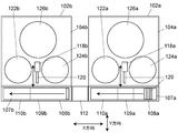
- the automatic analyzer 101 includes two automatic analyzers 102a and 102b and an inter-device transport device 112.
- the automatic analyzers 102a and 102b are arranged side by side in the X direction, which is one direction in the horizontal plane, and the transport mechanisms 106a and 106b of the automatic analyzers 102a and 102b are connected by the inter-device transport device 112. .
- the sample that has been sampled in the front-stage automatic analyzer 102a is introduced into the rear-stage automatic analyzer 102b via the inter-device transport apparatus 112, and the latter-stage automatic analyzer 102b also receives the sample. Samples are sampled and analyzed.
- the front-stage automatic analyzer 102a includes an analysis operation unit 104a, a transport mechanism 106a, and a rack introduction mechanism 118a.
- the transport mechanism 106a includes a belt conveyor 107a that transports a sample rack 120 holding a sample container to one side in the X direction (left side in FIGS. 1 and 2). The periphery of the belt conveyor 107a is covered with a cover.
- a sample rack placement unit 108a is provided on the start end side (right side in FIGS. 1 and 2) of the transport mechanism 106a, and a sample rack collection unit 110a is provided on the end side (left side in FIG. 1).
- the covers of the sample rack arranging unit 108a and the sample rack collecting unit 110a can be opened and closed. The user opens the cover of the sample rack arranging unit 108a and arranges the sample rack on the belt conveyor 107a, or covers the sample rack collecting unit 110a. You can open and remove the sample rack after sampling.
- the rack introduction mechanism 118a moves in the Y direction perpendicular to the X direction in the horizontal plane, holds the sample rack 120 on the belt conveyor 107a and introduces it to the analysis operation unit 104a side, or removes the sample rack 120 that has been sampled from the belt. It is arranged on the conveyor 107a.
- a sample rack introduction unit 109a is provided between the sample rack placement unit 108a and the sample rack collection unit 110a of the transport mechanism 106a, and the rack introduction mechanism 118a is provided from the sample rack introduction unit 109a to the sample rack 120 before sampling on the belt conveyor 107a. Are transferred into the analysis operation unit 104a, or the sample rack 120 after sampling is returned to the belt conveyor 107a.
- the analysis operation unit 104a includes a sample collection mechanism (not shown) having an inhalation probe for collecting a sample from the sample container transferred by the rack introduction mechanism 118a, a sample rack storage unit 124a, a material holding unit 122a, A measurement unit 126a is provided.
- a plurality of sample racks 120 transferred from the belt conveyor 107a by the rack introduction mechanism 118a are accommodated in the sample rack accommodating portion 124a.
- the sample rack accommodating portion 124a is a turntable, and the sample container on the sample rack 120 is arranged at a predetermined position when the suction probe collects a sample.
- a material container containing materials such as various reagents and calibration samples is arranged.
- the measuring unit 126a is provided with a plurality of containers for mixing the sample collected by the inhalation probe and the reagent, and configured to optically measure the reaction in the container.
- the sample rack 120 is stored in the sample rack storage unit 124a by the rack introduction mechanism 118a, the sample container held in the sample rack 120 is disposed at a predetermined position, and the sample is sampled by the inhalation probe. Is collected.
- the collected sample is injected into a container provided in the measurement unit 126a, and after a reagent corresponding to the analysis item is added, the reaction between the sample and the reagent is optically measured such as absorbance and fluorescence intensity.
- the latter-stage automatic analyzer 102b has the same configuration as the former-stage automatic analyzer 102a.
- the start end of the belt conveyor 107b provided in the transport mechanism 106b of the automatic analyzer 102b and the end of the front belt conveyor 107a are connected by an inter-device transport device 112.
- the inter-device transport device 112 includes a transport mechanism that holds the sample rack 120 at the end of the front belt conveyor 107a and is arranged at the start end of the rear belt conveyor 107b, and an openable / closable shielding cover 114 that covers the transport mechanism. I have. The transport mechanism will be described later.
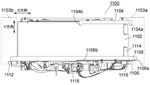
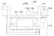
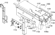
- the transport mechanism 1100 includes a table 1102 having a horizontal plane.
- the table 1102 is supported by a base 1118.
- the horizontal surface of the table 1102 is set to substantially the same height as the conveying surfaces of the belt conveyors 107a and 107b arranged at both ends.
- the position near the end of one side (right side in the figure) of the table 1102 is a transport start position 1103a where the sample rack to be transported is held to start transport, and the transport start position 1103a It arrange
- the position in the vicinity of the end of the table 1102 on the other side (left side in the figure) in the X direction is a sample rack transportation completion position 1103b, and the transportation belt completion position 1103b is such that the starting end of the belt conveyor 107b on the rear stage side is located. Has been placed.
- An arm member 1104 and an arm member 1106 extending in the X direction are arranged to face both side edges on the table 1102.
- the arm member 1104 and the arm member 1106 are driven in the X direction and the Y direction at the side edge of the table 1102.
- the arm member 1104 and the arm member 1106 move simultaneously in the same direction in the X direction and move in a symmetrical direction around the table 1102 in the Y direction.
- the arm member 1104 and a mechanism such as a motor for driving the arm member 1106 are housed inside the base 1118.
- the arm member 1104 includes a protrusion 1104a at an end portion on the transportation start position 1103a side, and a protrusion 1104b at an end portion on the transportation completion position 1103b side.
- the protrusion 1104a and the protrusion 1104b are fitted into a recess (not shown) provided on the side surface of the arm member 1104 of the sample rack to engage with the sample rack.
- the movement of the arm member 1104 in the Y direction is performed between a position where the protrusions 1104a and 1104b are fitted in the recess of the sample rack and a position where the arm does not contact the sample rack itself.
- the arm member 1106 includes a protrusion 1106a at the end of the transportation start position 1103a and a protrusion 1106b at the transportation completion position 1103b.
- the protrusion 1106a and the protrusion 1106b are engaged with the rear rear surface of the sample rack.
- the movement of the arm member 1106 in the Y direction is performed between a position where the protrusions 1106a and 1106b engage with the back surface of the sample rack and a position where the protrusions 1106a and 1106b do not contact the sample rack.
- Arm members 1104 and 1106 constitute a handler that holds the sample rack and slides the table 1102 from the transport start position 1103a to the transport completion position 1103b for transport.
- This handler is provided with holding portions at two locations on the transportation start position 1103a side and the transportation completion position 1103b side.
- the holding portion on the transport start position 1103a side is constituted by a projection 1104a of the arm member 1104 and the projection 1106a of the arm member 1106, and the holding portion on the transport completion position 1103b side is constituted by a projection 1104b of the arm member 1104 and a projection 1106b of the arm member 1106. Is done.
- the arm member 1104 and the arm member 1106 are collectively referred to as “handlers 1104 and 1106”, the holding portions on the transportation start position 1103a side of the handlers 1104 and 1106 are referred to as “first holding portions 1104a and 1106a”, and the transportation completion position 1103b side.
- the holding units are referred to as “second holding units 1104b and 1106b”.
- the first holding portions 1104a and 1106a insert the projection 1104a into the concave portion on the one side surface of the sample rack by sandwiching the sample rack from both sides at the ends of the arm members 1104 and 1106 on the transport start position 1103a side, and the sample The rear rear side opposite to the rack is supported by the protrusion 1106a.
- the second holding portions 1104b and 1106b are configured to fit the projection 1104b into the concave portion on one side of the sample rack by sandwiching the sample rack from both sides at the ends of the arm members 1104 and 1106 on the transport completion position 1103b side.
- the rear rear surface on the opposite side is supported by the protrusion 1106b.
- the handlers 1104 and 1106 move in the X direction while holding the sample rack, and transport the sample rack by sliding it on the table 1102.
- a guide rail 1108 that is fitted in a groove provided on a side surface of the sample rack that slides on the table 1102 and prevents the sample rack from overturning is provided on the side edge of the table 1102 on the arm member 1106 side.
- a start sensor 1110 for detecting the arrival of the sample rack at the transport start position 1103a is provided on the side of the transport start position 1103a.
- An end sensor 1112 for detecting the arrival of the sample rack at the transportation completion position 1103b is provided on the side of the transportation completion position 1103b.
- a stopper 1114 is provided in the vicinity of the transport start position 1103a for temporarily stopping the sample rack that has been transported to the transport start position 1103a by the preceding belt conveyor 107a at the transport start position 1103a. .
- a circuit board 1116 is provided on the side of the base 1118.
- the circuit board 1116 constitutes a control unit (hereinafter also referred to as a control unit 1116) that controls the operations of the handlers 1104 and 1106.
- the start sensor 1110 and the end sensor 1112 are connected to the circuit board 1116 via wiring. Signals from the start sensor 1110 and the end sensor 1112 are taken into the circuit board 1116 and are used to start a sample rack transport operation by the handlers 1104 and 1106 and to determine whether there is a sample rack transport error.
- FIG. 10 and FIG. 12 illustration of wiring and modules mounted on the circuit board 1116 are omitted.
- FIG. 11 some of the modules mounted on the circuit board 1116 are illustrated, but illustration of wiring is omitted.
- the first automatic analyzer 102a is provided with a controller 132a that controls the operation of the analysis operation unit 104a, the transport mechanism 106a, and the rack introduction mechanism 118a
- the second automatic analyzer 102b includes the analysis operation unit 104b, the transport mechanism 106b, and A controller 132b that controls the operation of the rack introduction mechanism 118b is provided.
- the inter-device transport apparatus 112 is provided with a control unit 1116 that controls the operation of the transport mechanism 1100.
- the control units 132a, 132b, and 1116 are connected to the arithmetic processing unit 134, respectively. Measurement data obtained by the analysis operation unit 104a of the first automatic analyzer 102a and measurement data obtained by the analysis operation unit 104b of the second automatic analysis device 102b are taken into the arithmetic processing unit 134 via the control unit 132a, The arithmetic processing unit 134 identifies and quantifies the components in the sample.
- the arithmetic processing unit 134 is realized by, for example, a general-purpose personal computer or a dedicated computer.
- the user can manage the operation of each of the devices 102a, 102b and 112 individually and centrally via the arithmetic processing unit 134.
- the arithmetic processing unit 134 is similar to the arithmetic processing unit 2 of the embodiment described with reference to FIGS. 1 to 6, such as material information, analysis item information, calibration information, and calibration item information.
- an information storage unit for storing the information, a control unit, an information storage unit, an information editing unit, an information rewrite management unit, an information display unit, an ID information input unit, and a calculation unit. Since each means is the same as that of the arithmetic processing apparatus 2 of the embodiment described with reference to FIGS.
- the information storage unit of the arithmetic processing apparatus 134 is stored. Is stored with unique information such as material information and analysis item information provided by the device manufacturer or the material manufacturer, and editing of the unique information by the user is restricted by information rewriting management means.
- the arithmetic processing unit 134 stores the information input unit 136 for the user to input information to the arithmetic processing unit 134, the result of the arithmetic operation performed by the arithmetic means of the arithmetic processing unit 134, and the information storage unit.
- An information display unit 138 for displaying various information is connected.
Landscapes
- Physics & Mathematics (AREA)
- Health & Medical Sciences (AREA)
- Life Sciences & Earth Sciences (AREA)
- Chemical & Material Sciences (AREA)
- Analytical Chemistry (AREA)
- Biochemistry (AREA)
- General Health & Medical Sciences (AREA)
- General Physics & Mathematics (AREA)
- Immunology (AREA)
- Pathology (AREA)
- Automatic Analysis And Handling Materials Therefor (AREA)
Abstract
自動分析装置は、マテリアル情報及び分析項目情報をユーザーが作成したユーザー作成情報とユーザー作成情報でない固有情報とで区別し、それぞれを区別するための識別子を付加して情報記憶部に格納し、ユーザーが情報記憶部に格納されている情報の編集を行なう際には、ユーザー作成情報のみその編集を許可するように構成されている。
Description
本発明は、設置されたサンプルについてユーザーにより指定された分析項目を自動的に実行する自動分析装置に関するものである。
サンプルの分析を自動的に行なう自動分析装置は、ユーザーがサンプルを収容した容器を所定の位置に設置すると、その容器から所定量のサンプルを採取して分析容器に分注し、指定された分析項目に応じてその分析容器に所定量の試薬を添加し、その吸光度等を測定することにより、サンプル中に含まれる成分の濃度の定量等を行なう(例えば、特許文献1参照。)。かかる自動分析装置には、マテリアルに関する情報(以下、マテリアル情報)と分析項目情報が格納されている。
マテリアルとは試薬や校正用サンプル、精度管理サンプルなどを意味する。校正用サンプルとは、サンプルの吸光度等の測定値を定量値(濃度)に換算するための校正係数の導出に用いられるサンプルであり、測定項目に対して濃度が既知のサンプルである。精度管理サンプルとは、この精度管理サンプルを測定して得られた定量値とこの精度管理サンプルに対して設定されている目標値との差をとり、装置の測定精度を評価するためのサンプルである。
マテリアル情報には、マテリアルそれぞれを識別化するためのマテリアルコードやマテリアル名、ロット、使用期限といった情報(校正用サンプルであれば各分析項目に対する既知の濃度値、精度管理サンプルであれば目標値も含む)が含まれる。
分析項目情報には、それぞれの分析項目を識別化する項目コードや項目名、対象サンプル種別、定量値単位などの情報のほか、それぞれの分析項目において使用するマテリアルの種類(マテリアルコード)や量に関する情報も含まれる。
上記のマテリアル情報や分析項目情報は、装置に設置されるマテリアルによって異なってくるものである。このため、マテリアル情報や分析項目情報はマテリアルメーカーによって作成され、それらの情報を格納したCD(コンパクトディスク)などの記録媒体がユーザーに提供され、その記録媒体を介して装置に導入される。
マテリアルメーカーは、提供するマテリアルに対応したマテリアル情報と分析項目情報が使用されることを前提として、そのマテリアルを使用した分析結果に一定の精度を保証している。したがって、ユーザーは、マテリアルメーカーの用意した分析項目の中から選択した分析項目については、その分析項目の分析結果についてマテリアルメーカーが保証する精度が得られる。
自動分析装置は、マテリアルメーカーの用意した分析項目とは別に、ユーザー独自の分析項目を実行することができるように、分析項目情報やマテリアル情報を編集する機能を備えていることが多い。ユーザーが既存の分析項目とは別の新たな分析項目を作成しようとして誤ってマテリアルメーカーの用意した分析項目情報を改変してしまった場合、その分析項目を指定したときにその分析項目の正しい分析が実行されず、マテリアルメーカーの用意した分析項目であるにもかかわらず、マテリアルメーカーの保証する分析精度が得られないという事態が生じる。
従来の自動分析装置では、分析項目情報やマテリアル情報を編集する際に、表示されている情報が改変して良いものであるか否かの判断が難しかった。特に、ユーザーが独自に分析項目を作成して追加した場合には、マテリアルメーカーの用意した分析項目情報とユーザーが新たに作成した分析項目情報との区別が付きにくく、ユーザーがマテリアルメーカーの用意した分析項目情報を誤って改変してしまう虞があった。
そこで、本発明は、自動分析装置に格納されている分析項目情報やマテリアル情報が誤って改変されないようにすることを目的とするものである。
本発明にかかる自動分析装置は、マテリアル保持部、分析動作部、情報記憶部、情報格納手段、情報編集手段及び情報書換管理手段を備えている。マテリアル保持部は試薬及び校正用サンプルを含む複数のマテリアルを保持する。分析動作部はマテリアル保持部に保持されているマテリアルを用いてサンプルの分析動作を実行する。情報記憶部はマテリアルに関する情報であるマテリアル情報及びサンプルの分析項目に関する情報である分析項目情報を記憶する。情報格納手段は外部から入力されたマテリアル情報及び分析項目情報を情報記憶部に格納するものであり、情報記憶部に格納するそれぞれの情報について、その情報がユーザーの作成したユーザー作成情報であるときはユーザー作成情報であることを示す識別子をその情報に付加し、ユーザー作成情報ではない固有情報であるときは固有情報であることを示す識別子をその情報に付加して情報記憶部に格納するようになっている。制御手段は、情報記憶部の情報に基づいて、ユーザーにより指定された分析項目が実行されるように分析動作部を制御するように構成されている。情報編集手段は、情報記憶部に記憶されている情報のいずれかをユーザーに指定させ、ユーザーによって指定された情報の編集を行なう情報編集モードを実行し、既存の情報を編集された情報に書き換えるように構成されている。情報書換管理手段は、情報編集モードにおいて、ユーザーの指定した情報に付加されている識別子に基づき、その情報がユーザー作成情報であるときは書換えを許可し、その情報が固有情報であるときは書換えを禁止するように構成されている。
すなわち、本発明の自動分析装置は、マテリアル情報及び分析項目情報をユーザーが作成したユーザー作成情報とユーザー作成情報でない固有情報とで区別し、それぞれを区別するための識別子を付加して情報記憶部に格納し、ユーザーが情報記憶部に格納されている情報の編集を行なう際には、ユーザー作成情報のみその編集を許可するように構成されているものである。
ここで、固有情報とは、ユーザー作成情報でない情報として定義されているが、ユーザー作成情報でない情報とは、自動分析装置のメーカーによって予め自動分析装置(情報記憶部)に用意されている分析項目情報のほか、マテリアルメーカーによって提供されたマテリアル情報やそのマテリアル情報に関連する分析項目情報などである。かかる固有情報に基づいて分析がなされる限りはメーカーの保証する分析精度が得られるが、これらの固有情報が改変されてしまうとメーカーの保証する分析精度が得られなくなる虞がある。そのため、本発明では、ユーザーによる固有情報の編集を禁止し、ユーザー作成情報のみその編集を許可するように構成している。
一般に、情報記憶部に格納されるマテリアル情報と分析項目情報にはそれぞれの情報を識別化するための識別コードが含まれており、装置内においてマテリアル情報や分析項目情報はその識別コードによって管理されている。その場合、情報格納手段は、情報記憶部に格納する情報それぞれの識別コードに識別子を付加するように構成されていることが好ましい。各情報の管理に用いられている識別コードにその情報が固有情報であるかユーザー作成情報であるかを示す識別子が付加されていれば、各情報が固有情報であるかユーザー作成情報であるかの判別が容易になる。
本発明の自動分析装置では、さらに、ユーザーに対し情報を表示する情報表示部、及び情報編集モードが実行されたときに、情報記憶部に記憶されている情報を、それぞれの情報に付加されている識別子をユーザーによって認識される状態で表示する情報表示手段を備えていることが好ましい。そうすれば、情報表示部に表示された情報のそれぞれについて、その情報がユーザー作成情報であるか固有情報であるかを認識しやすくなり、編集が可能な情報と不可能な情報とを容易に判別することができる。
上記の場合、情報表示手段は、情報編集モードにおいて、ユーザーの指定した情報が固有情報であるときは、情報表示部にその旨を表示するように構成されていることが好ましい。そうすれば、ユーザーが編集対象の情報として固有情報を誤って指定しても、その情報が固有情報であることをユーザーがすぐに認識できるようになり、情報編集作業の効率が向上する。
本発明の自動分析装置の好ましい実施の態様では、情報格納手段が、マテリアル情報及び分析項目情報が記憶媒体を介して外部から入力された情報に固有情報であることを示す識別子を付加して情報記憶部に格納するように構成されている。マテリアルを装置に導入する際、そのマテリアルについてのマテリアル情報やそれに関連する分析項目情報はマテリアルメーカーが作成し、CD(コンパクトディスク)などの記憶媒体に格納された状態でユーザーに提供され、ユーザーはその記憶媒体を介してマテリアル情報や分析項目情報を装置に入力するようになっていることが一般的である。したがって、記憶媒体を介して装置へ入力される情報は固有情報であるため、固有情報であることを示す識別子を付加するようにしておくことで、マテリアルメーカーによって提供された情報の改変を防止することができる。
操作者の権限を特定するための操作者IDを入力させるID入力手段をさらに備え、情報書換管理手段は、操作者の入力した操作者IDが固有情報に付された識別子と関連付けられたIDであるときは、固有情報の書換えを許可するように構成されていることが好ましい。例えば、情報記憶部に格納されている固有情報に不具合が発見された場合など、固有情報を編集する必要が生じることがありうる。そこで、固有情報を編集する権限を有する者であるか否かを操作者IDによって判別し、権限を有する者による編集を許可することで、ユーザーによる固有情報の改変を防止しながらメーカーなど一定の権限を有する者による固有情報の編集が可能となる。
また、ユーザーが既存の固有情報を使って新たに分析項目などを作成したい場合がある。そこで、情報書換管理手段は、既存の固有情報を複製することによって作成された新たな情報はユーザー作成情報として認識するように構成されていることが好ましい。これにより、ユーザーが既存の固有情報を複製した場合には、その複製情報がユーザー作成情報として認識され、その編集が可能となるので、既存の固有を用いて新たな分析項目などを作成することができるようになる。
なお、本発明は、自動分析装置が、マテリアル保持部及び分析動作部をそれぞれ備えた複数の分析装置と、それらの分析装置のすべてに接続され各分析装置を一元的に管理する一つの演算処理装置とで構成された自動分析装置に対しても適用することができる。その場合、情報記憶部、情報格納手段、制御手段、情報編集手段及び情報書換管理手段は演算処理装置に設けられている。
本発明の自動分析装置は、マテリアル情報及び分析項目情報をユーザーが作成したユーザー作成情報とユーザー作成情報でない固有情報とで区別し、それぞれを区別するための識別子を付加して情報記憶部に格納し、ユーザーが情報記憶部に格納されている情報の編集を行なう際には、ユーザー作成情報のみその編集を許可するように構成されているので、装置メーカーやマテリアルメーカーが作成した固有情報についてユーザーによる改変を防止することができる。
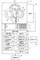
図1を用いて自動分析装置の一実施例について説明する。
この自動分析装置は分析装置本体1と演算処理装置2からなる。演算処理装置2は分析装置本体1と接続されており、分析装置本体1の動作管理と分析装置本体1で得られたデータに基づいて種々の演算処理を行なうものである。
分析装置本体1は分析動作部3、搬送機構4及びそれらの動作を制御する制御部50を備えている。搬送機構4はサンプルラック6を載置して搬送するベルトコンベアである。搬送機構4によって搬送されるサンプルラック6には複数のサンプル容器8が保持され、サンプル容器8内に分析動作部3で分析されるサンプルが収容される。
分析動作部3と搬送機構4との間でサンプルラック6を搬送するラック導入機構10が設けられている。ラック導入機構10は搬送機構4上の所定の位置でサンプルラック6を保持して所定のサンプリング位置へ搬送し、サンプリングが終了すると保持したサンプルラック6を搬送機構4へ戻すように構成されている。
分析動作部3は、サンプリングアーム12、反応容器搬送機構14、搬送アーム18、測定部20、マテリアル供給アーム22及びマテリアル保持部24を備えている。
サンプリングアーム12は基端を中心に回転するアームであり、先端側にサンプリング用のニードルを備えている。ラック導入機構10はサンプル容器8をサンプリングアーム12のニードルの軌道上に配置することができる。サンプル容器8のサンプルを採取する際は、サンプリングアーム12がニードルの軌道上に配置されたサンプル容器8内にニードルの先端を挿入し、ニードルの先端からサンプルを吸入して採取する。
反応容器搬送機構14は複数の反応容器16を同一の円周上で保持しており、その円周方向へ回転することによって反応容器16を所定の位置へ搬送するものである。反応容器16はサンプリングアーム12のニードルが採取したサンプルを収容して反応させる容器である。反応容器搬送機構14は、反応容器16をサンプリングアーム12のニードルの軌道上の位置へ配置することができ、サンプル容器8から採取したサンプルはサンプリングアーム12のニードルによって反応容器16に分注される。
搬送アーム18は基端を中心に回転するアームであり、その先端側に反応容器16を保持する保持部を備えている。反応容器搬送機構14は、サンプルを収容した反応容器16を搬送アーム18の保持部の軌道上の位置に配置することができ、搬送アーム18は反応容器搬送機構14により搬送されてきた反応容器16を保持し、保持部の軌道上の複数箇所に設けられた測定部20のいずれかに配置することができる。
マテリアル保持部24は複数のマテリアル容器26を同一円周上で保持し、その円周方向へ回転することによってマテリアル容器26を所定の位置へ搬送するものである。マテリアル容器26には試薬や校正用サンプルなどのマテリアルが収容されている。マテリアル供給アーム22は搬送アーム18と同心円を描くように回転するアームであり、その先端側にマテリアル容器26からマテリアルを採取するためのニードルを備えている。マテリアル供給アーム22は、先端側のニードルでマテリアルを吸入し、測定部20の反応容器16にそのマテリアルを分注することができる。
測定部20は、サンプルや試薬が分注された反応容器16を収容し、反応容器16の温度を制御しながら反応容器16内の吸光度変化などの光学的変化を測定するように構成されている。
演算処理装置2は汎用のパーソナルコンピュータ(PC)又は専用のコンピュータである。演算処理装置2には情報入力部46と情報表示部48が接続されている。情報入力部46はキーボードやマウスのほか、CDなどの情報記憶媒体を介して情報を入力するものも含む。情報表示部48は汎用のPCモニタ又は専用のモニタである。
演算処理装置2は種々の情報を記憶する情報記憶部30を備えている。情報記憶部30には、マテリアル保持部24に設置された各マテリアルのマテリアル情報を格納するマテリアル情報記憶領域32、分析項目情報を格納する分析項目情報記憶領域33、測定データを定量値に校正するための校正情報を格納する校正情報記憶領域34及び校正項目を格納する校正項目情報記憶領域35が設けられている。
演算処理装置2は、制御手段36、情報格納手段38、情報編集手段40、情報書換管理手段42、情報表示手段43、ID入力手段44及び演算手段45を備えている。これらの手段はプログラムの実行によって得られる機能である。
制御手段36は、ユーザーにより指定された分析項目や校正項目を実行するように、情報記憶部30に記憶されているマテリアル情報と分析項目情報に基づいて分析装置本体1の制御部50に制御信号を与える。
情報格納手段38は、情報入力部46を介して入力されたマテリアル情報や分析項目情報をそれぞれの識別コードとともに情報記憶部30に格納する。情報記憶部30に格納されたマテリアル情報や分析項目情報は識別コードによって管理される。情報格納手段38は、情報記憶部30に格納するそれぞれの情報について、その情報がユーザーの作成したユーザー作成情報である場合にはそのことを示す識別子(ユーザー識別子)をその情報の識別コードに付加し、その情報がメーカーの作成した固有情報である場合にはそのことを示す識別子(固有情報識別子)をその情報の識別コードに付加する。
情報編集手段40は、ユーザーからの要求があったときに、ユーザーが情報記憶部30に格納されているマテリアル情報や分析項目情報の編集を行なうことができる状態(情報編集モード)にする。情報編集モードでは、後述する情報表示手段43によって情報表示部48に情報記憶部30に格納されている情報がリスト表示され、ユーザーはそのリストから編集したい情報を選択してその編集を行なうことができる。
情報記憶部30に格納されている情報の書換えは情報書換管理手段42によって管理されている。情報書換管理手段42は、情報編集モードの際に、ユーザーが選択した情報の識別コードに付加された識別子に基づいてその情報の書換えの許可と不許可を判断し、ユーザー識別子が識別コードに付加されている情報については書換えを許可し、固有情報識別子が識別コードに付加されている情報については書換えを許可しないようになっている。
情報表示手段43は、必要に応じて分析装置本体1で得られた分析結果等のデータや情報記憶部30に格納されている情報を情報表示部48に表示する。情報編集モードの際には、ユーザーからの要求に応じて情報記憶部30に記憶されているマテリアル情報や分析項目情報をそれぞれの識別コードとともに情報表示部48に表示する。
図6は情報編集モードの際に情報表示部48に表示される情報の一例のキャリブレータ(校正用サンプル)リストである。このリストでは、各キャリブレータの名前とともにそれぞれの識別コードが表記されており、各識別コードに「IL」又は「US」という識別子が付加されている。この例においては、「IL」はマテリアルメーカーが作成した固有情報であることを示す固有情報識別子であり、「US」はユーザーが作成したユーザー作成情報であることを示すユーザー識別子である。ユーザーは、情報記憶部30に格納されている情報の編集を行なう際に、各情報の識別コードに付加されている識別子を参照することで、その情報がメーカーによって作成されたものであるかユーザーが作成したものであるかの判別が容易である。
ID入力手段44は、操作者がこのシステムにログインする際又は情報編集モードが実行された際に、操作者に対して操作者IDの入力を求める。入力されたIDによって、現在の操作者が一般ユーザーであるかマテリアルメーカーや装置メーカーなど権限を有する者であるかが判別される。情報書換管理手段42は、入力されたIDが固有情報の識別コードに付加されている固有情報識別子と関連付けられたものである場合、固有情報についてもその書換えを許可するようになっている。固有情報識別子と関連付けられた操作者IDとは、例えば固有情報に固有情報識別子として「IL」が付加されている場合、その固有情報識別子と一致する操作者ID「IL」が挙げられる。
演算手段45は、分析装置本体1の測定部20で得られた測定データを取得し、情報記憶部30に格納されている校正情報に基づいてその測定データを校正し、分析項目で求められている特定成分の定量値を算出する。
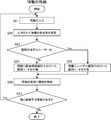
次に、この自動分析装置における1サンプルに対する分析動作についての一例を図1とともに図2のフローチャートを用いて説明する。
ラック導入機構10によって所定のサンプリング位置に分析対象のサンプル容器8が配置されると、例えばバーコードの読取り(バーコードリーダーなどの図示は省略)などによってそのサンプルの識別コードなどの情報を取得する(ステップS1)。そのサンプルに対して実行すべき分析項目は予めユーザーによって指定されており、ユーザーによって指定されている分析項目の情報を情報記憶部30から取得する(ステップS2)。
分析項目で指定されている量のサンプルをサンプリングアーム12のニードルで採取し、反応容器搬送機構14によって所定位置に配置された反応容器16に分注する(ステップS3)。
分析項目で使用する試薬をマテリアルコードに基づいて特定する(ステップS4)。マテリアル保持部24に設置されている試薬などのマテリアルの設置位置は、例えば各マテリアルの容器に付されたバーコードなどから読み取られたマテリアルコードによって管理されている。分析項目情報には、それぞれの分析項目で使用する試薬などのマテリアルがマテリアルコードによって指定されており、そのマテリアルコードに基づいてマテリアル保持部24に設置されているマテリアルの中から使用マテリアルが特定される。マテリアル供給アーム22のニードルで特定した試薬を分析項目で指定されている量だけ採取し、サンプルを収容した反応容器16に分注する(ステップS5)。
分析項目において反応容器16内の攪拌が指定されていれば攪拌を実行し、攪拌が指定されていなければ測定へ移行する(ステップS6、ステップS7及びステップS8)。反応容器16内の攪拌は、例えばマテリアルアーム22のニードルによる吸入と吐出を反応容器16内で繰り返すことにより実行する。測定は、サンプルと試薬を収容した反応容器16は搬送アーム18によっていずれかの測定部20へ搬送して実行する。
測定部20で得られた測定データは制御部50を介して演算処理装置2に取り込まれ、情報記憶部30に予め用意された校正情報に基づいた校正が行なわれ、サンプル中の特定成分の定量値が算出される(ステップS9)。
ユーザーにより同じサンプルについて別の分析項目が指定されている場合には、その分析項目を実行するように上記ステップS2~S9までの動作を実行する(ステップS10)。
次に、分析装置本体1の測定部20で得られた測定データを定量値に校正するための校正情報の作成動作についての一例を図1とともに図3のフローチャートを用いて説明する。
情報記憶部30にはユーザーが校正項目を指定すると(ステップS11)、指定された校正項目情報を情報記憶部30から取得する(ステップS12)。校正項目で使用する校正用サンプルをマテリアルコードに基づいて特定する(ステップS13)。校正用サンプルを収容した容器はマテリアル保持部24に設置されており、その設置位置は試薬と同様にマテリアルコードによって管理されている。校正用サンプルとは特定成分の濃度が既知のサンプルであり、校正用サンプルを用いて分析項目と同様の測定を行なって吸光度などの測定データを得ることで、測定データと実際の濃度との相関関係(定量計算ファクタ)を得ることができる。定量計算ファクタとは、例えば検量線である。校正用サンプルにおける特定成分の濃度はマテリアル情報として情報記憶部30に格納されている。
校正項目で指定されている量の校正用サンプルをマテリアル供給アーム22のニードルで採取し、反応容器16に分注する(ステップS14)。続いて、校正項目で使用する試薬をマテリアルコードに基づいて特定し、指定されている量の試薬を採取して校正用サンプルを収容した反応容器16に分注する(ステップS15)。校正項目において反応容器16内の攪拌が指定されていれば攪拌を実行し、攪拌が指定されていなければ測定へ移行する(ステップS16、ステップS17及びステップS18)。
校正用サンプルにおける既知の特定成分濃度と測定により得られた測定データから校正情報を算出する(ステップS19)。算出された校正情報は情報記憶部30に格納される(ステップS20)。
情報記憶部30への情報の格納動作についての一例を図1とともに図4のフローチャートを用いて説明する。
情報記憶部30への情報の格納は、情報編集モードにおいて行なわれるか又はCDなどの記憶媒体を介してインポートされることで実行される。情報編集モードにおいて新たなマテリアル情報又は分析項目情報が情報入力部46を介して入力されると(ステップS21)、情報格納手段40はその情報の作成者を確認する(ステップS22)。情報作成者がユーザーであればその情報の識別コードにユーザー識別子を付加し(ステップS23及びステップS25)、情報作成者がマテリアルメーカーや装置メーカーなど一定の権限者であればその情報の識別コードに固有情報識別子を付加する(ステップS23及びステップS24)。入力された情報の作成者は、その情報入力時にログインしている操作者のIDに基づいてユーザーか一定の権限者かを判断する。
情報記憶部30に入力された情報を識別子の付いた識別コードとともに格納する(ステップS26)。他にも情報記憶部30に入力すべき情報がある場合は、上記ステップS21~S26までの動作を繰り返す(ステップS27)。
マテリアル情報や分析項目情報がCDなどの記憶媒体を介してインポートされた場合、情報格納手段40はその情報の作成者を一定の権限者とし、その情報の識別コードに固有情報識別子を付加して情報記憶部30に格納する。また、記憶媒体を介してインポートされる情報にすでに固有情報識別子が付加されている場合には、そのまま情報記憶部30に格納される。
ユーザーが情報記憶部30にすでに格納されている情報を利用して新たな情報を作成したい場合には、既存情報をコピーして新たな項目情報として利用することができる。既存情報からコピーされた新たな情報は、ユーザーが新たに作成した情報として情報格納手段38が認識し、その識別コードにユーザー識別子を付加して情報記憶部30に格納する。この新たな情報はユーザー識別子が付加されているため、ユーザーが編集して書き換えることができる。
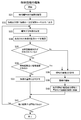
次に、情報記憶部30に格納されている情報の編集動作についての一例を図1とともに図5のフローチャートを用いて説明する。
情報編集手段40によって情報編集モードが実行されると、情報書換管理手段42が情報編集者の権限を確認するとともに(ステップS31)、情報表示手段43が図6に示されているような情報編集者が編集を希望する種類の情報(例えば分析項目情報、試薬情報、校正用サンプル情報)の一覧を情報表示部48に表示する(ステップS32)。情報編集者の権限は、ログインしている操作者のIDによって確認することができる。
情報編集者が情報表示部48に表示された情報から編集を希望する情報を指定すると(ステップS33)、情報書換管理手段42は指定された情報の識別コードを確認する(ステップS34)。
識別コードに固有情報識別子が付加されていて情報編集者がマテリアルメーカーや装置メーカーなどの一定の権限者である場合は、情報書換管理手段42がその情報の書換えを許可し(ステップS35、ステップS36及びステップS38)、情報編集者はその既存情報を編集して書き換えることが可能となる(ステップS39及びステップS40)。識別コードに固有情報識別子が付加されているが情報編集者が一般ユーザーである場合は、情報書換管理手段42がその情報の書換えを許可せず(ステップS35、ステップS36及びステップS37)、情報編集者はその情報の書換えを行なうことはできない。その場合、情報表示部48に情報書換えが許可されない旨の表示が行なわれる。
情報編集者が指定した情報の識別コードにユーザー識別子が付加されている場合、情報書換管理手段42は情報編集者の権限に関係なくその情報の書換えを許可し(ステップS35及びステップS38)、情報編集者はその既存情報を編集して書き換えることが可能となる(ステップS39及びステップS40)。情報編集者が編集を希望する情報のそれぞれについて上記ステップS31~ステップS40の処理が行なわれる(ステップS41)。
次に、自動分析装置の他の実施例について図7及び図8を用いて説明する。
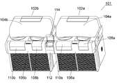
この自動分析装置101は、2つの自動分析装置102a,102bと装置間輸送装置112により構成されている。自動分析装置102a,102bは水平面内の一方向であるX方向に並んで配置され、両自動分析装置102a,102bのそれぞれの搬送機構106aと106bの間が装置間輸送装置112によって連結されている。この自動分析装置101では、前段側の自動分析装置102aにおいてサンプリングの終了したサンプルが装置間輸送装置112を介して後段側の自動分析装置102bに導入され、後段側の自動分析装置102bにおいてもそのサンプルのサンプリングと分析がなされる。
前段側の自動分析装置102aは、分析動作部104a、搬送機構106a及びラック導入機構118aを備えている。搬送機構106aはサンプル容器を保持したサンプルラック120をX方向の一方側(図1及び図2において左側)へ搬送するベルトコンベア107aを備えている。ベルトコンベア107aの周囲はカバーで覆われている。搬送機構106aの始端側(図1及び図2において右側)にサンプルラック配置部108aが設けられ、終端側(同図において左側)にサンプルラック回収部110aが設けられている。サンプルラック配置部108aとサンプルラック回収部110aのカバーは開閉可能であり、ユーザーがサンプルラック配置部108aのカバーを開けてサンプルラックをベルトコンベア107a上に配置したり、サンプルラック回収部110aのカバーを開けてサンプリングの終了したサンプルラックを取り出したりすることができる。
ラック導入機構118aは水平面内においてX方向と直交するY方向へ移動し、ベルトコンベア107a上のサンプルラック120を保持して分析動作部104a側へ導入したり、サンプリングの終了したサンプルラック120をベルトコンベア107a上に配置したりするものである。搬送機構106aのサンプルラック配置部108aとサンプルラック回収部110aの間にサンプルラック導入部109aが設けられており、ラック導入機構118aはサンプルラック導入部109aからベルトコンベア107a上のサンプリング前サンプルラック120を分析動作部104a内に移送したり,サンプリング後のサンプルラック120をベルトコンベア107a上に戻したりするようになっている。
分析動作部104aは、ラック導入機構118aにより移送されたサンプル容器からサンプルを採取するための吸入プローブなどを有するサンプル採取機構(図示は省略)のほか、サンプルラック収容部124a、マテリアル保持部122a及び測定部126aを備えている。サンプルラック収容部124aには、ラック導入機構118aによってベルトコンベア107a上から移送されたサンプルラック120が複数収容される。サンプルラック収容部124aはターンテーブルになっていて、サンプルラック120上のサンプル容器を、吸入プローブがサンプルを採取するときの所定位置に配置する。マテリアル保持部122aには種々の試薬や校正用試料などのマテリアルを収容したマテリアル容器が配置されている。測定部126aには、吸入プローブによって採取されたサンプルと試薬を混合する容器が複数個設けられており、容器内の反応を光学的に測定するように構成されている。かかる構成により、分析動作部104aでは、サンプルラック120がラック導入機構118aによってサンプルラック収容部124aに収容され、そのサンプルラック120に保持されているサンプル容器が所定位置に配置され、吸入プローブによってサンプルが採取される。採取されたサンプルは測定部126aに設けられた容器に注入され、分析項目に応じた試薬が添加された後、サンプルと試薬の反応が吸光度や蛍光強度など光学的に測定される。
後段側の自動分析装置102bは前段側の自動分析装置102aと同じ構成を有する。自動分析装置102bの搬送機構106bに設けられたベルトコンベア107bの始端と前段側のベルトコンベア107aの終端とは装置間輸送装置112によって連結されている。
装置間輸送装置112は、前段側のベルトコンベア107aの終端にきたサンプルラック120を保持して後段側のベルトコンベア107bの始端に配置する輸送機構とその輸送機構を覆う開閉式の遮蔽カバー114を備えている。輸送機構については後述する。
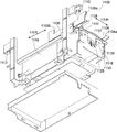
装置間輸送装置112の輸送機構の一例について図9から図12を用いて説明する。
輸送機構1100は水平面を有するテーブル1102を備えている。テーブル1102は基台1118によって支持されている。テーブル1102の水平面は両端に配置されるベルトコンベア107a,107bの搬送面とほぼ同じ高さに設定されている。テーブル1102のX方向における一方側(図において右側)の端部近傍の位置は輸送対象であるサンプルラックを保持して輸送を開始する輸送開始位置1103aであり、この輸送開始位置1103aに前段側のベルトコンベア107aの終端がくるように配置されている。テーブル1102のX方向における他方側(図において左側)の端部近傍の位置はサンプルラックの輸送完了位置1103bとなっており、この輸送完了位置1103bに後段側のベルトコンベア107bの始端がくるように配置されている。
テーブル1102上の両側縁部にX方向に延びた腕部材1104と腕部材1106が対向して配置されている。腕部材1104と腕部材1106はテーブル1102の側縁部においてX方向とY方向へ駆動される。腕部材1104と腕部材1106は、X方向に対しては同時に同方向へ連動して移動し、Y方向に対してテーブル1102を中心として対称な方向へ連動して移動する。図には示されていないが、腕部材1104と腕部材1106を駆動するモータ等の機構は基台1118の内部に収容されている。
腕部材1104は、輸送開始位置1103a側端部に突起1104aを備え、輸送完了位置1103b側端部に突起1104bを備えている。突起1104aと突起1104bはサンプルラックの腕部材1104側側面に設けられた凹部(図示は省略)に嵌め込まれてサンプルラックと係合するものである。腕部材1104のY方向への移動は、突起1104a,1104bがサンプルラックの凹部に嵌め込まれる位置とサンプルラック自体に接触しない位置との間で行なわれる。
腕部材1106は、輸送開始位置1103a側端部に突起1106aを備え、輸送完了位置1103b側に突起1106bを備えている。突起1106aと突起1106bはサンプルラックの後背面と係合するものである。腕部材1106のY方向への移動は、突起1106a,1106bがサンプルラックの背面に係合する位置と突起1106a,1106bがサンプルラックに接触しない位置との間で行なわれる。
腕部材1104と1106は、サンプルラックを保持して輸送開始位置1103aから輸送完了位置1103bまでテーブル1102上をスライドさせて輸送するハンドラを構成している。このハンドラは、輸送開始位置1103a側と輸送完了位置1103b側の2箇所に保持部を備えている。輸送開始位置1103a側の保持部は腕部材1104の突起1104aと腕部材1106の突起1106aで構成され、輸送完了位置1103b側の保持部は腕部材1104の突起1104bと腕部材1106の突起1106bで構成される。
以下において、腕部材1104と腕部材1106をまとめて「ハンドラ1104,1106」、ハンドラ1104,1106の輸送開始位置1103a側の保持部を「第1保持部1104a,1106a」、輸送完了位置1103b側の保持部を「第2保持部1104b,1106b」と称する。
第1保持部1104a,1106aは、腕部材1104と1106の輸送開始位置1103a側の端部でサンプルラックを両側から挟み込むことによって、サンプルラックの一方側の側面の凹部に突起1104aを嵌め込むとともにサンプルラックの反対側後背面を突起1106aで支持する。第2保持部1104b,1106bは、腕部材1104と1106の輸送完了位置1103b側の端部でサンプルラックを両側から挟み込むことによって、サンプルラックの一側面の凹部に突起1104bを嵌め込むとともにサンプルラックの反対側後背面を突起1106bで支持する。ハンドラ1104,1106は、サンプルラックを保持した状態でX方向へ移動し、サンプルラックをテーブル1102上でスライドさせて輸送する。テーブル1102の腕部材1106側の側縁部には、テーブル1102上をスライドするサンプルラックの側面に設けられた溝に嵌め込まれてサンプルラックの転倒を防止するガイドレール1108が設けられている。
輸送開始位置1103aの側方には、輸送開始位置1103aへのサンプルラックの到達を検知する開始センサ1110が設けられている。輸送完了位置1103bの側方には、輸送完了位置1103bへのサンプルラックの到達を検知する終了センサ1112が設けられている。また、輸送開始位置1103aの近傍に、前段側のベルトコンベア107aによって輸送開始位置1103aまで搬送されてきたサンプルラックを輸送開始位置1103aで一時的に停止させておくためのストッパ1114が設けられている。
基台1118の側部に回路基板1116が設けられている。回路基板1116はハンドラ1104,1106の動作を制御する制御部(以下において、制御部1116とも記載)をなしている。開始センサ1110及び終了センサ1112は配線を介して回路基板1116に接続されている。開始センサ1110及び終了センサ1112の信号は回路基板1116に取り込まれ、ハンドラ1104,1106によるサンプルラックの輸送動作の開始やサンプルラックの輸送エラーの有無の判定に利用される。
なお、図10及び図12では、配線や回路基板1116に搭載されているモジュールの図示を省略している。図11では回路基板1116に搭載されているモジュールの一部は図示しているが、配線の図示を省略している。
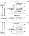
次に、この自動分析装置101全体の制御系統について図13を用いて説明する。
第1自動分析装置102aには分析動作部104a、搬送機構106a及びラック導入機構118aの動作を制御する制御部132aが設けられ、第2自動分析装置102bには分析動作部104b、搬送機構106b及びラック導入機構118bの動作を制御する制御部132bが設けられている。装置間輸送装置112には輸送機構1100の動作を制御する制御部1116が設けられている。
制御部132a,132b及び1116はそれぞれ演算処理装置134と接続されている。第1自動分析装置102aの分析動作部104aで得られた測定データや第2自動分析装置102bの分析動作部104bで得られた測定データは制御部132aを介して演算処理装置134に取り込まれ、演算処理装置134においてサンプル中の成分の同定や定量が行なわれる。演算処理装置134は例えば汎用のパーソナルコンピュータや専用のコンピュータにより実現される。
ユーザーは演算処理装置134を介して各装置102a,102b及び112の動作を個別にかつ一元的に管理することができる。図示は省略されているが、演算処理装置134は、図1から図6までを用いて説明した実施例の演算処理装置2と同様に、マテリアル情報や分析項目情報、校正情報、校正項目情報などの情報を記憶する情報記憶部と、制御手段や情報格納手段、情報編集手段、情報書換管理手段、情報表示手段、ID情報入力手段、演算手段といった手段を備えている。各手段については図1から図6までを用いて説明した実施例の演算処理装置2のものと同じであるため、ここでの詳細な説明は省略するが、演算処理装置134の情報記憶部には、装置メーカーやマテリアルメーカーの提供するマテリアル情報や分析項目情報などの固有情報が格納され、これらの固有情報のユーザーによる編集は情報書換管理手段によって制限されている。
演算処理装置134には、ユーザーが演算処理装置134に対して情報入力を行なうための情報入力部136と、演算処理装置134の演算手段により実行された演算の結果や情報記憶部に格納されている種々の情報などを表示する情報表示部138が接続されている。
1,101 分析装置本体
2,134 演算処理装置
3,104a,104b 分析動作部
4,106a,106b 搬送機構
6,120 サンプルラック
8 サンプル容器
10,118a,118b ラック導入機構
12 サンプリングアーム
14 反応容器搬送部
16 反応容器
18 搬送アーム
20 測定部
22 マテリアル供給アーム
24,122a,122b マテリアル保持部
26 マテリアル容器
30 情報記憶部
32 マテリアル情報記憶領域
33 分析項目情報記憶領域
34 校正情報記憶領域
35 校正項目情報記憶領域
36 制御手段
38 情報格納手段
40 情報編集手段
42 情報書換管理手段
43 情報表示手段
44 ID入力手段
45 演算手段
46,136 情報入力部
48,138 情報表示部
50,132a,132b,1116 制御部
112 装置間輸送装置
2,134 演算処理装置
3,104a,104b 分析動作部
4,106a,106b 搬送機構
6,120 サンプルラック
8 サンプル容器
10,118a,118b ラック導入機構
12 サンプリングアーム
14 反応容器搬送部
16 反応容器
18 搬送アーム
20 測定部
22 マテリアル供給アーム
24,122a,122b マテリアル保持部
26 マテリアル容器
30 情報記憶部
32 マテリアル情報記憶領域
33 分析項目情報記憶領域
34 校正情報記憶領域
35 校正項目情報記憶領域
36 制御手段
38 情報格納手段
40 情報編集手段
42 情報書換管理手段
43 情報表示手段
44 ID入力手段
45 演算手段
46,136 情報入力部
48,138 情報表示部
50,132a,132b,1116 制御部
112 装置間輸送装置
Claims (8)
- 試薬及び校正用サンプルを含む複数のマテリアルを保持するマテリアル保持部と、
前記マテリアル保持部に保持されている前記マテリアルを用いてサンプルの分析動作を実行する分析動作部と、
前記マテリアルに関する情報であるマテリアル情報及びサンプルの分析項目に関する情報である分析項目情報を記憶する情報記憶部と、
外部から入力された前記マテリアル情報及び前記分析項目情報を前記情報記憶部に格納する情報格納手段であって、前記情報記憶部に格納するそれぞれの情報について、その情報がユーザーの作成したユーザー作成情報であるときはユーザー作成情報であることを示す識別子をその情報に付加し、前記ユーザー作成情報ではない固有情報であるときは固有情報であることを示す識別子をその情報に付加して前記情報記憶部に格納する情報格納手段と、
前記情報記憶部の情報に基づいて、ユーザーにより指定された分析項目が実行されるように前記分析動作部を制御する制御手段と、
前記情報記憶部に記憶されている情報のいずれかをユーザーに指定させ、ユーザーによって指定された情報の編集を行なう情報編集モードを実行し、既存の情報を編集された情報に書き換える情報編集手段と、
前記情報編集モードにおいて、ユーザーの指定した情報に付加されている識別子に基づき、その情報が前記ユーザー作成情報であるときは書換えを許可し、その情報が前記固有情報であるときは書換えを禁止する情報書換管理手段と、を備えた自動分析装置。 - 前記情報記憶部に格納される前記マテリアル情報と前記分析項目情報にはそれぞれの情報を識別化するための識別コードが含まれており、
前記情報格納手段は、前記情報記憶部に格納する情報それぞれの前記識別コードに前記識別子を付加するように構成されている請求項1に記載の自動分析装置。 - ユーザーに対し情報を表示する情報表示部と、
前記情報編集モードが実行されたときに、前記情報記憶部に記憶されている情報を、それぞれの情報に付加されている前記識別子がユーザーによって認識される状態で表示する情報表示手段と、を備えた請求項1又は2に記載の自動分析装置。 - 前記情報表示手段は、前記情報編集モードにおいて、ユーザーの指定した情報が前記固有情報であるときは、前記情報表示部にその旨を表示するように構成されている請求項3に記載の自動分析装置。
- 前記情報格納手段は、前記マテリアル情報及び前記分析項目情報が記憶媒体を介して外部から入力された情報に固有情報であることを示す識別子を付加して前記情報記憶部に格納するように構成されている請求項1から4のいずれか一項に記載の自動分析装置。
- 操作者の権限を特定するための操作者IDを入力させるID入力手段をさらに備え、
前記情報書換管理手段は、操作者の入力した操作者IDが前記固有情報に付された識別子と関連付けられたIDであるときは、前記固有情報の書換えを許可するように構成されている請求項1から5のいずれか一項に記載の自動分析装置。 - 前記情報書換管理手段は、既存の固有情報を複製することによって作成された新たな情報をユーザー作成情報として認識するように構成されている請求項1から6のいずれか一項に記載の自動分析装置。
- 該自動分析装置は、前記マテリアル保持部及び前記分析動作部をそれぞれ備えた複数の分析装置と、それらの前記分析装置のすべてに接続され前記各分析装置を一元的に管理する一つの演算処理装置とで構成されており、
前記情報記憶部、前記情報格納手段、前記制御手段、前記情報編集手段及び前記情報書換管理手段は前記演算処理装置に設けられている請求項1から7のいずれか一項に記載の自動分析装置。
Priority Applications (1)
| Application Number | Priority Date | Filing Date | Title |
|---|---|---|---|
| PCT/JP2013/082474 WO2015083235A1 (ja) | 2013-12-03 | 2013-12-03 | 自動分析装置 |
Applications Claiming Priority (1)
| Application Number | Priority Date | Filing Date | Title |
|---|---|---|---|
| PCT/JP2013/082474 WO2015083235A1 (ja) | 2013-12-03 | 2013-12-03 | 自動分析装置 |
Publications (1)
| Publication Number | Publication Date |
|---|---|
| WO2015083235A1 true WO2015083235A1 (ja) | 2015-06-11 |
Family
ID=53273032
Family Applications (1)
| Application Number | Title | Priority Date | Filing Date |
|---|---|---|---|
| PCT/JP2013/082474 Ceased WO2015083235A1 (ja) | 2013-12-03 | 2013-12-03 | 自動分析装置 |
Country Status (1)
| Country | Link |
|---|---|
| WO (1) | WO2015083235A1 (ja) |
Cited By (1)
| Publication number | Priority date | Publication date | Assignee | Title |
|---|---|---|---|---|
| JP2022043809A (ja) * | 2020-09-04 | 2022-03-16 | 株式会社島津製作所 | 自動分析装置 |
Citations (6)
| Publication number | Priority date | Publication date | Assignee | Title |
|---|---|---|---|---|
| JPH01250758A (ja) * | 1988-03-31 | 1989-10-05 | Toshiba Corp | 自動化学分析装置 |
| JP2002340904A (ja) * | 2001-05-15 | 2002-11-27 | Shimadzu Corp | 機器分析用データ管理装置 |
| JP2004309249A (ja) * | 2003-04-04 | 2004-11-04 | Shimadzu Corp | 分析装置 |
| JP2011075468A (ja) * | 2009-09-30 | 2011-04-14 | Sysmex Corp | 検体検査装置 |
| JP2011137662A (ja) * | 2009-12-25 | 2011-07-14 | Beckman Coulter Inc | 自動分析装置および分析システム |
| JP2011226868A (ja) * | 2010-04-16 | 2011-11-10 | Furuno Electric Co Ltd | 検体分析装置及び分析制御プログラム |
-
2013
- 2013-12-03 WO PCT/JP2013/082474 patent/WO2015083235A1/ja not_active Ceased
Patent Citations (6)
| Publication number | Priority date | Publication date | Assignee | Title |
|---|---|---|---|---|
| JPH01250758A (ja) * | 1988-03-31 | 1989-10-05 | Toshiba Corp | 自動化学分析装置 |
| JP2002340904A (ja) * | 2001-05-15 | 2002-11-27 | Shimadzu Corp | 機器分析用データ管理装置 |
| JP2004309249A (ja) * | 2003-04-04 | 2004-11-04 | Shimadzu Corp | 分析装置 |
| JP2011075468A (ja) * | 2009-09-30 | 2011-04-14 | Sysmex Corp | 検体検査装置 |
| JP2011137662A (ja) * | 2009-12-25 | 2011-07-14 | Beckman Coulter Inc | 自動分析装置および分析システム |
| JP2011226868A (ja) * | 2010-04-16 | 2011-11-10 | Furuno Electric Co Ltd | 検体分析装置及び分析制御プログラム |
Cited By (1)
| Publication number | Priority date | Publication date | Assignee | Title |
|---|---|---|---|---|
| JP2022043809A (ja) * | 2020-09-04 | 2022-03-16 | 株式会社島津製作所 | 自動分析装置 |
Similar Documents
| Publication | Publication Date | Title |
|---|---|---|
| EP1873530B1 (en) | Sample analyzer | |
| CN102866246B (zh) | 样本分析装置及信息处理装置 | |
| EP1873531B1 (en) | Sample analyzer | |
| US5646046A (en) | Method and instrument for automatically performing analysis relating to thrombosis and hemostasis | |
| CN107407686B (zh) | 自动分析装置 | |
| JP4979307B2 (ja) | 血液試料測定装置 | |
| WO2017033641A1 (ja) | 自動分析装置 | |
| CN110892270B (zh) | 自动分析装置 | |
| JP2007263912A (ja) | 血液凝固分析装置 | |
| JP2012108010A (ja) | 自動分析装置 | |
| JP4986487B2 (ja) | 血液凝固時間測定装置 | |
| JP2018080957A (ja) | 自動分析装置及びプログラム | |
| JP6419641B2 (ja) | 自動分析装置及び多重測定方法 | |
| WO2015083235A1 (ja) | 自動分析装置 | |
| JP5336555B2 (ja) | 検体分析装置 | |
| US12265093B2 (en) | Automatic analyzer and non-transitory computer-readable recording medium storing program | |
| US20120321514A1 (en) | Analyzing system and method of managing measurement results | |
| CN102221621B (zh) | 检体分析装置及分析控制方法 | |
| JP2008051765A (ja) | 自動分析装置および自動分析方法 | |
| US20230056397A1 (en) | Automatic analysis device, display system of automatic analysis device, and display method in automatic analysis device | |
| JP2006208099A (ja) | 自動分析機器の制御装置 | |
| WO2019021645A1 (ja) | 自動分析装置および画像処理方法 | |
| EP3553530B1 (en) | Automatic analyzer and program | |
| JP2013024785A (ja) | 自動分析装置 | |
| US20250277805A1 (en) | Selecting a position for multiple process fluids in an analysis device |
Legal Events
| Date | Code | Title | Description |
|---|---|---|---|
| 121 | Ep: the epo has been informed by wipo that ep was designated in this application |
Ref document number: 13898689 Country of ref document: EP Kind code of ref document: A1 |
|
| NENP | Non-entry into the national phase |
Ref country code: DE |
|
| NENP | Non-entry into the national phase |
Ref country code: JP |
|
| 122 | Ep: pct application non-entry in european phase |
Ref document number: 13898689 Country of ref document: EP Kind code of ref document: A1 |