WO2015080259A1 - 硬質カーボン膜製nf又はro膜、濾過フィルター、2層接合型濾過フィルター及びそれらの製造方法 - Google Patents
硬質カーボン膜製nf又はro膜、濾過フィルター、2層接合型濾過フィルター及びそれらの製造方法 Download PDFInfo
- Publication number
- WO2015080259A1 WO2015080259A1 PCT/JP2014/081601 JP2014081601W WO2015080259A1 WO 2015080259 A1 WO2015080259 A1 WO 2015080259A1 JP 2014081601 W JP2014081601 W JP 2014081601W WO 2015080259 A1 WO2015080259 A1 WO 2015080259A1
- Authority
- WO
- WIPO (PCT)
- Prior art keywords
- film
- membrane
- hard carbon
- carbon film
- diamond
- Prior art date
Links
- 239000012528 membrane Substances 0.000 title claims abstract description 326
- 229910021385 hard carbon Inorganic materials 0.000 title claims abstract description 184
- 238000001914 filtration Methods 0.000 title claims abstract description 167
- 238000004519 manufacturing process Methods 0.000 title claims abstract description 55
- 238000000034 method Methods 0.000 title claims abstract description 34
- 238000001223 reverse osmosis Methods 0.000 title abstract description 110
- 238000001728 nano-filtration Methods 0.000 title abstract description 9
- 239000011148 porous material Substances 0.000 claims abstract description 96
- 239000003960 organic solvent Substances 0.000 claims abstract description 48
- XLYOFNOQVPJJNP-UHFFFAOYSA-N water Substances O XLYOFNOQVPJJNP-UHFFFAOYSA-N 0.000 claims abstract description 27
- OKTJSMMVPCPJKN-UHFFFAOYSA-N Carbon Chemical compound [C] OKTJSMMVPCPJKN-UHFFFAOYSA-N 0.000 claims description 179
- 229910052799 carbon Inorganic materials 0.000 claims description 173
- 239000010410 layer Substances 0.000 claims description 158
- 229920002492 poly(sulfone) Polymers 0.000 claims description 103
- DMLAVOWQYNRWNQ-UHFFFAOYSA-N azobenzene Chemical compound C1=CC=CC=C1N=NC1=CC=CC=C1 DMLAVOWQYNRWNQ-UHFFFAOYSA-N 0.000 claims description 86
- 238000000108 ultra-filtration Methods 0.000 claims description 72
- 239000000758 substrate Substances 0.000 claims description 68
- FAPWRFPIFSIZLT-UHFFFAOYSA-M Sodium chloride Chemical compound [Na+].[Cl-] FAPWRFPIFSIZLT-UHFFFAOYSA-M 0.000 claims description 46
- 230000015572 biosynthetic process Effects 0.000 claims description 30
- 238000004544 sputter deposition Methods 0.000 claims description 25
- 239000011780 sodium chloride Substances 0.000 claims description 23
- 238000005268 plasma chemical vapour deposition Methods 0.000 claims description 20
- 238000005304 joining Methods 0.000 claims description 19
- XUIMIQQOPSSXEZ-UHFFFAOYSA-N Silicon Chemical compound [Si] XUIMIQQOPSSXEZ-UHFFFAOYSA-N 0.000 claims description 17
- 229910052710 silicon Inorganic materials 0.000 claims description 17
- 239000010703 silicon Substances 0.000 claims description 17
- 239000000463 material Substances 0.000 claims description 16
- 239000007864 aqueous solution Substances 0.000 claims description 14
- WQZGKKKJIJFFOK-GASJEMHNSA-N Glucose Natural products OC[C@H]1OC(O)[C@H](O)[C@@H](O)[C@@H]1O WQZGKKKJIJFFOK-GASJEMHNSA-N 0.000 claims description 12
- 239000008103 glucose Substances 0.000 claims description 12
- PEDCQBHIVMGVHV-UHFFFAOYSA-N Glycerine Chemical compound OCC(O)CO PEDCQBHIVMGVHV-UHFFFAOYSA-N 0.000 claims description 10
- CZMRCDWAGMRECN-UGDNZRGBSA-N Sucrose Chemical compound O[C@H]1[C@H](O)[C@@H](CO)O[C@@]1(CO)O[C@@H]1[C@H](O)[C@@H](O)[C@H](O)[C@@H](CO)O1 CZMRCDWAGMRECN-UGDNZRGBSA-N 0.000 claims description 10
- 229930006000 Sucrose Natural products 0.000 claims description 10
- 239000005720 sucrose Substances 0.000 claims description 10
- 239000002253 acid Substances 0.000 claims description 7
- WQZGKKKJIJFFOK-VFUOTHLCSA-N beta-D-glucose Chemical compound OC[C@H]1O[C@@H](O)[C@H](O)[C@@H](O)[C@@H]1O WQZGKKKJIJFFOK-VFUOTHLCSA-N 0.000 claims description 7
- 239000000203 mixture Substances 0.000 claims description 7
- 239000011521 glass Substances 0.000 claims description 6
- 229910052751 metal Inorganic materials 0.000 claims description 6
- 239000002184 metal Substances 0.000 claims description 6
- 238000004528 spin coating Methods 0.000 claims description 6
- 238000005406 washing Methods 0.000 claims description 6
- 239000002202 Polyethylene glycol Substances 0.000 claims description 5
- 238000007607 die coating method Methods 0.000 claims description 5
- 238000007598 dipping method Methods 0.000 claims description 5
- 235000011187 glycerol Nutrition 0.000 claims description 5
- 229920001223 polyethylene glycol Polymers 0.000 claims description 5
- 238000001291 vacuum drying Methods 0.000 claims description 5
- 238000005266 casting Methods 0.000 claims description 4
- 239000002344 surface layer Substances 0.000 claims description 2
- 238000000926 separation method Methods 0.000 abstract description 34
- 150000002500 ions Chemical class 0.000 abstract description 12
- 230000001747 exhibiting effect Effects 0.000 abstract 1
- 239000010408 film Substances 0.000 description 383
- LFQSCWFLJHTTHZ-UHFFFAOYSA-N Ethanol Chemical compound CCO LFQSCWFLJHTTHZ-UHFFFAOYSA-N 0.000 description 72
- 239000011550 stock solution Substances 0.000 description 46
- 230000004907 flux Effects 0.000 description 34
- VLKZOEOYAKHREP-UHFFFAOYSA-N n-Hexane Chemical compound CCCCCC VLKZOEOYAKHREP-UHFFFAOYSA-N 0.000 description 33
- 239000000975 dye Substances 0.000 description 31
- 239000000706 filtrate Substances 0.000 description 29
- 239000000243 solution Substances 0.000 description 29
- VZSRBBMJRBPUNF-UHFFFAOYSA-N 2-(2,3-dihydro-1H-inden-2-ylamino)-N-[3-oxo-3-(2,4,6,7-tetrahydrotriazolo[4,5-c]pyridin-5-yl)propyl]pyrimidine-5-carboxamide Chemical compound C1C(CC2=CC=CC=C12)NC1=NC=C(C=N1)C(=O)NCCC(N1CC2=C(CC1)NN=N2)=O VZSRBBMJRBPUNF-UHFFFAOYSA-N 0.000 description 28
- 239000007789 gas Substances 0.000 description 24
- 238000012360 testing method Methods 0.000 description 22
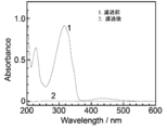
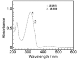
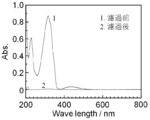
- 238000000862 absorption spectrum Methods 0.000 description 19
- 238000011156 evaluation Methods 0.000 description 16
- XDTMQSROBMDMFD-UHFFFAOYSA-N Cyclohexane Chemical compound C1CCCCC1 XDTMQSROBMDMFD-UHFFFAOYSA-N 0.000 description 15
- HMUNWXXNJPVALC-UHFFFAOYSA-N 1-[4-[2-(2,3-dihydro-1H-inden-2-ylamino)pyrimidin-5-yl]piperazin-1-yl]-2-(2,4,6,7-tetrahydrotriazolo[4,5-c]pyridin-5-yl)ethanone Chemical compound C1C(CC2=CC=CC=C12)NC1=NC=C(C=N1)N1CCN(CC1)C(CN1CC2=C(CC1)NN=N2)=O HMUNWXXNJPVALC-UHFFFAOYSA-N 0.000 description 14
- 150000002894 organic compounds Chemical class 0.000 description 12
- 239000007788 liquid Substances 0.000 description 11
- 239000002904 solvent Substances 0.000 description 11
- XKRFYHLGVUSROY-UHFFFAOYSA-N Argon Chemical compound [Ar] XKRFYHLGVUSROY-UHFFFAOYSA-N 0.000 description 10
- IJGRMHOSHXDMSA-UHFFFAOYSA-N Atomic nitrogen Chemical compound N#N IJGRMHOSHXDMSA-UHFFFAOYSA-N 0.000 description 10
- 230000000903 blocking effect Effects 0.000 description 8
- CONKBQPVFMXDOV-QHCPKHFHSA-N 6-[(5S)-5-[[4-[2-(2,3-dihydro-1H-inden-2-ylamino)pyrimidin-5-yl]piperazin-1-yl]methyl]-2-oxo-1,3-oxazolidin-3-yl]-3H-1,3-benzoxazol-2-one Chemical compound C1C(CC2=CC=CC=C12)NC1=NC=C(C=N1)N1CCN(CC1)C[C@H]1CN(C(O1)=O)C1=CC2=C(NC(O2)=O)C=C1 CONKBQPVFMXDOV-QHCPKHFHSA-N 0.000 description 7
- NIPNSKYNPDTRPC-UHFFFAOYSA-N N-[2-oxo-2-(2,4,6,7-tetrahydrotriazolo[4,5-c]pyridin-5-yl)ethyl]-2-[[3-(trifluoromethoxy)phenyl]methylamino]pyrimidine-5-carboxamide Chemical compound O=C(CNC(=O)C=1C=NC(=NC=1)NCC1=CC(=CC=C1)OC(F)(F)F)N1CC2=C(CC1)NN=N2 NIPNSKYNPDTRPC-UHFFFAOYSA-N 0.000 description 7
- VNWKTOKETHGBQD-UHFFFAOYSA-N methane Chemical compound C VNWKTOKETHGBQD-UHFFFAOYSA-N 0.000 description 7
- 238000012546 transfer Methods 0.000 description 7
- UHOVQNZJYSORNB-UHFFFAOYSA-N Benzene Chemical compound C1=CC=CC=C1 UHOVQNZJYSORNB-UHFFFAOYSA-N 0.000 description 6
- KRHYYFGTRYWZRS-UHFFFAOYSA-N Fluorane Chemical compound F KRHYYFGTRYWZRS-UHFFFAOYSA-N 0.000 description 6
- IMNFDUFMRHMDMM-UHFFFAOYSA-N N-Heptane Chemical compound CCCCCCC IMNFDUFMRHMDMM-UHFFFAOYSA-N 0.000 description 6
- AFCARXCZXQIEQB-UHFFFAOYSA-N N-[3-oxo-3-(2,4,6,7-tetrahydrotriazolo[4,5-c]pyridin-5-yl)propyl]-2-[[3-(trifluoromethoxy)phenyl]methylamino]pyrimidine-5-carboxamide Chemical compound O=C(CCNC(=O)C=1C=NC(=NC=1)NCC1=CC(=CC=C1)OC(F)(F)F)N1CC2=C(CC1)NN=N2 AFCARXCZXQIEQB-UHFFFAOYSA-N 0.000 description 6
- 238000000635 electron micrograph Methods 0.000 description 6
- 229920000642 polymer Polymers 0.000 description 6
- WGYKZJWCGVVSQN-UHFFFAOYSA-N propylamine Chemical compound CCCN WGYKZJWCGVVSQN-UHFFFAOYSA-N 0.000 description 6
- 229910052786 argon Inorganic materials 0.000 description 5
- 238000002474 experimental method Methods 0.000 description 5
- 229910002804 graphite Inorganic materials 0.000 description 5
- 239000010439 graphite Substances 0.000 description 5
- 229910052757 nitrogen Inorganic materials 0.000 description 5
- 230000035699 permeability Effects 0.000 description 5
- 239000012466 permeate Substances 0.000 description 5
- 239000000126 substance Substances 0.000 description 5
- YJLUBHOZZTYQIP-UHFFFAOYSA-N 2-[5-[2-(2,3-dihydro-1H-inden-2-ylamino)pyrimidin-5-yl]-1,3,4-oxadiazol-2-yl]-1-(2,4,6,7-tetrahydrotriazolo[4,5-c]pyridin-5-yl)ethanone Chemical compound C1C(CC2=CC=CC=C12)NC1=NC=C(C=N1)C1=NN=C(O1)CC(=O)N1CC2=C(CC1)NN=N2 YJLUBHOZZTYQIP-UHFFFAOYSA-N 0.000 description 4
- VVJKKWFAADXIJK-UHFFFAOYSA-N Allylamine Chemical compound NCC=C VVJKKWFAADXIJK-UHFFFAOYSA-N 0.000 description 4
- KAKZBPTYRLMSJV-UHFFFAOYSA-N Butadiene Chemical compound C=CC=C KAKZBPTYRLMSJV-UHFFFAOYSA-N 0.000 description 4
- JUJWROOIHBZHMG-UHFFFAOYSA-N Pyridine Chemical compound C1=CC=NC=C1 JUJWROOIHBZHMG-UHFFFAOYSA-N 0.000 description 4
- WYURNTSHIVDZCO-UHFFFAOYSA-N Tetrahydrofuran Chemical compound C1CCOC1 WYURNTSHIVDZCO-UHFFFAOYSA-N 0.000 description 4
- PNEYBMLMFCGWSK-UHFFFAOYSA-N aluminium oxide Inorganic materials [O-2].[O-2].[O-2].[Al+3].[Al+3] PNEYBMLMFCGWSK-UHFFFAOYSA-N 0.000 description 4
- 125000004122 cyclic group Chemical group 0.000 description 4
- DIOQZVSQGTUSAI-UHFFFAOYSA-N decane Chemical compound CCCCCCCCCC DIOQZVSQGTUSAI-UHFFFAOYSA-N 0.000 description 4
- 229920006351 engineering plastic Polymers 0.000 description 4
- 238000001471 micro-filtration Methods 0.000 description 4
- TVMXDCGIABBOFY-UHFFFAOYSA-N octane Chemical compound CCCCCCCC TVMXDCGIABBOFY-UHFFFAOYSA-N 0.000 description 4
- 239000003921 oil Substances 0.000 description 4
- 238000002360 preparation method Methods 0.000 description 4
- WZFUQSJFWNHZHM-UHFFFAOYSA-N 2-[4-[2-(2,3-dihydro-1H-inden-2-ylamino)pyrimidin-5-yl]piperazin-1-yl]-1-(2,4,6,7-tetrahydrotriazolo[4,5-c]pyridin-5-yl)ethanone Chemical compound C1C(CC2=CC=CC=C12)NC1=NC=C(C=N1)N1CCN(CC1)CC(=O)N1CC2=C(CC1)NN=N2 WZFUQSJFWNHZHM-UHFFFAOYSA-N 0.000 description 3
- WEVYAHXRMPXWCK-UHFFFAOYSA-N Acetonitrile Chemical compound CC#N WEVYAHXRMPXWCK-UHFFFAOYSA-N 0.000 description 3
- OKKJLVBELUTLKV-UHFFFAOYSA-N Methanol Chemical compound OC OKKJLVBELUTLKV-UHFFFAOYSA-N 0.000 description 3
- 239000004642 Polyimide Substances 0.000 description 3
- HSFWRNGVRCDJHI-UHFFFAOYSA-N alpha-acetylene Natural products C#C HSFWRNGVRCDJHI-UHFFFAOYSA-N 0.000 description 3
- 229910052782 aluminium Inorganic materials 0.000 description 3
- XAGFODPZIPBFFR-UHFFFAOYSA-N aluminium Chemical compound [Al] XAGFODPZIPBFFR-UHFFFAOYSA-N 0.000 description 3
- 125000004429 atom Chemical group 0.000 description 3
- 229920002678 cellulose Polymers 0.000 description 3
- 239000001913 cellulose Substances 0.000 description 3
- 229920006037 cross link polymer Polymers 0.000 description 3
- 238000010586 diagram Methods 0.000 description 3
- 229910003460 diamond Inorganic materials 0.000 description 3
- 239000010432 diamond Substances 0.000 description 3
- 230000005684 electric field Effects 0.000 description 3
- 125000002534 ethynyl group Chemical group [H]C#C* 0.000 description 3
- 238000002955 isolation Methods 0.000 description 3
- 230000003204 osmotic effect Effects 0.000 description 3
- 229920001721 polyimide Polymers 0.000 description 3
- 238000012545 processing Methods 0.000 description 3
- KZEVSDGEBAJOTK-UHFFFAOYSA-N 1-(2,4,6,7-tetrahydrotriazolo[4,5-c]pyridin-5-yl)-2-[5-[2-[[3-(trifluoromethoxy)phenyl]methylamino]pyrimidin-5-yl]-1,3,4-oxadiazol-2-yl]ethanone Chemical compound N1N=NC=2CN(CCC=21)C(CC=1OC(=NN=1)C=1C=NC(=NC=1)NCC1=CC(=CC=C1)OC(F)(F)F)=O KZEVSDGEBAJOTK-UHFFFAOYSA-N 0.000 description 2
- SXAMGRAIZSSWIH-UHFFFAOYSA-N 2-[3-[2-(2,3-dihydro-1H-inden-2-ylamino)pyrimidin-5-yl]-1,2,4-oxadiazol-5-yl]-1-(2,4,6,7-tetrahydrotriazolo[4,5-c]pyridin-5-yl)ethanone Chemical compound C1C(CC2=CC=CC=C12)NC1=NC=C(C=N1)C1=NOC(=N1)CC(=O)N1CC2=C(CC1)NN=N2 SXAMGRAIZSSWIH-UHFFFAOYSA-N 0.000 description 2
- JQMFQLVAJGZSQS-UHFFFAOYSA-N 2-[4-[2-(2,3-dihydro-1H-inden-2-ylamino)pyrimidin-5-yl]piperazin-1-yl]-N-(2-oxo-3H-1,3-benzoxazol-6-yl)acetamide Chemical compound C1C(CC2=CC=CC=C12)NC1=NC=C(C=N1)N1CCN(CC1)CC(=O)NC1=CC2=C(NC(O2)=O)C=C1 JQMFQLVAJGZSQS-UHFFFAOYSA-N 0.000 description 2
- YLZOPXRUQYQQID-UHFFFAOYSA-N 3-(2,4,6,7-tetrahydrotriazolo[4,5-c]pyridin-5-yl)-1-[4-[2-[[3-(trifluoromethoxy)phenyl]methylamino]pyrimidin-5-yl]piperazin-1-yl]propan-1-one Chemical compound N1N=NC=2CN(CCC=21)CCC(=O)N1CCN(CC1)C=1C=NC(=NC=1)NCC1=CC(=CC=C1)OC(F)(F)F YLZOPXRUQYQQID-UHFFFAOYSA-N 0.000 description 2
- ZOXJGFHDIHLPTG-UHFFFAOYSA-N Boron Chemical compound [B] ZOXJGFHDIHLPTG-UHFFFAOYSA-N 0.000 description 2
- VEXZGXHMUGYJMC-UHFFFAOYSA-M Chloride anion Chemical compound [Cl-] VEXZGXHMUGYJMC-UHFFFAOYSA-M 0.000 description 2
- HEDRZPFGACZZDS-UHFFFAOYSA-N Chloroform Chemical compound ClC(Cl)Cl HEDRZPFGACZZDS-UHFFFAOYSA-N 0.000 description 2
- OAICVXFJPJFONN-UHFFFAOYSA-N Phosphorus Chemical compound [P] OAICVXFJPJFONN-UHFFFAOYSA-N 0.000 description 2
- 239000004743 Polypropylene Substances 0.000 description 2
- 238000010521 absorption reaction Methods 0.000 description 2
- 150000001335 aliphatic alkanes Chemical class 0.000 description 2
- 230000004075 alteration Effects 0.000 description 2
- QVGXLLKOCUKJST-UHFFFAOYSA-N atomic oxygen Chemical compound [O] QVGXLLKOCUKJST-UHFFFAOYSA-N 0.000 description 2
- 230000005540 biological transmission Effects 0.000 description 2
- 229910052796 boron Inorganic materials 0.000 description 2
- 230000006837 decompression Effects 0.000 description 2
- 238000000151 deposition Methods 0.000 description 2
- 230000000694 effects Effects 0.000 description 2
- 238000007429 general method Methods 0.000 description 2
- ZQBFAOFFOQMSGJ-UHFFFAOYSA-N hexafluorobenzene Chemical compound FC1=C(F)C(F)=C(F)C(F)=C1F ZQBFAOFFOQMSGJ-UHFFFAOYSA-N 0.000 description 2
- UQEAIHBTYFGYIE-UHFFFAOYSA-N hexamethyldisiloxane Chemical compound C[Si](C)(C)O[Si](C)(C)C UQEAIHBTYFGYIE-UHFFFAOYSA-N 0.000 description 2
- 239000001257 hydrogen Substances 0.000 description 2
- 229910052739 hydrogen Inorganic materials 0.000 description 2
- 125000004435 hydrogen atom Chemical group [H]* 0.000 description 2
- 230000002209 hydrophobic effect Effects 0.000 description 2
- 239000011261 inert gas Substances 0.000 description 2
- 239000002346 layers by function Substances 0.000 description 2
- 238000001755 magnetron sputter deposition Methods 0.000 description 2
- 238000005259 measurement Methods 0.000 description 2
- 238000000691 measurement method Methods 0.000 description 2
- 239000004745 nonwoven fabric Substances 0.000 description 2
- 229910052760 oxygen Inorganic materials 0.000 description 2
- 239000001301 oxygen Substances 0.000 description 2
- 229910052698 phosphorus Inorganic materials 0.000 description 2
- 239000011574 phosphorus Substances 0.000 description 2
- 229920002647 polyamide Polymers 0.000 description 2
- 229920000728 polyester Polymers 0.000 description 2
- -1 polypropylene Polymers 0.000 description 2
- 229920001155 polypropylene Polymers 0.000 description 2
- 230000008569 process Effects 0.000 description 2
- UMJSCPRVCHMLSP-UHFFFAOYSA-N pyridine Natural products COC1=CC=CN=C1 UMJSCPRVCHMLSP-UHFFFAOYSA-N 0.000 description 2
- 150000003254 radicals Chemical class 0.000 description 2
- 238000011160 research Methods 0.000 description 2
- 150000003839 salts Chemical class 0.000 description 2
- 229910001415 sodium ion Inorganic materials 0.000 description 2
- YLQBMQCUIZJEEH-UHFFFAOYSA-N tetrahydrofuran Natural products C=1C=COC=1 YLQBMQCUIZJEEH-UHFFFAOYSA-N 0.000 description 2
- 230000007704 transition Effects 0.000 description 2
- OHVLMTFVQDZYHP-UHFFFAOYSA-N 1-(2,4,6,7-tetrahydrotriazolo[4,5-c]pyridin-5-yl)-2-[4-[2-[[3-(trifluoromethoxy)phenyl]methylamino]pyrimidin-5-yl]piperazin-1-yl]ethanone Chemical compound N1N=NC=2CN(CCC=21)C(CN1CCN(CC1)C=1C=NC(=NC=1)NCC1=CC(=CC=C1)OC(F)(F)F)=O OHVLMTFVQDZYHP-UHFFFAOYSA-N 0.000 description 1
- LDXJRKWFNNFDSA-UHFFFAOYSA-N 2-(2,4,6,7-tetrahydrotriazolo[4,5-c]pyridin-5-yl)-1-[4-[2-[[3-(trifluoromethoxy)phenyl]methylamino]pyrimidin-5-yl]piperazin-1-yl]ethanone Chemical compound C1CN(CC2=NNN=C21)CC(=O)N3CCN(CC3)C4=CN=C(N=C4)NCC5=CC(=CC=C5)OC(F)(F)F LDXJRKWFNNFDSA-UHFFFAOYSA-N 0.000 description 1
- KFDVPJUYSDEJTH-UHFFFAOYSA-N 4-ethenylpyridine Chemical compound C=CC1=CC=NC=C1 KFDVPJUYSDEJTH-UHFFFAOYSA-N 0.000 description 1
- 229920000049 Carbon (fiber) Polymers 0.000 description 1
- 102100026816 DNA-dependent metalloprotease SPRTN Human genes 0.000 description 1
- 101710175461 DNA-dependent metalloprotease SPRTN Proteins 0.000 description 1
- 229920002307 Dextran Polymers 0.000 description 1
- 101100136092 Drosophila melanogaster peng gene Proteins 0.000 description 1
- OTMSDBZUPAUEDD-UHFFFAOYSA-N Ethane Chemical compound CC OTMSDBZUPAUEDD-UHFFFAOYSA-N 0.000 description 1
- UFHFLCQGNIYNRP-UHFFFAOYSA-N Hydrogen Chemical compound [H][H] UFHFLCQGNIYNRP-UHFFFAOYSA-N 0.000 description 1
- FXHOOIRPVKKKFG-UHFFFAOYSA-N N,N-Dimethylacetamide Chemical compound CN(C)C(C)=O FXHOOIRPVKKKFG-UHFFFAOYSA-N 0.000 description 1
- 239000004696 Poly ether ether ketone Substances 0.000 description 1
- 239000004952 Polyamide Substances 0.000 description 1
- 239000004695 Polyether sulfone Substances 0.000 description 1
- 229910003481 amorphous carbon Inorganic materials 0.000 description 1
- 238000004458 analytical method Methods 0.000 description 1
- 239000011260 aqueous acid Substances 0.000 description 1
- 238000001241 arc-discharge method Methods 0.000 description 1
- 238000009835 boiling Methods 0.000 description 1
- 238000004364 calculation method Methods 0.000 description 1
- 125000004432 carbon atom Chemical group C* 0.000 description 1
- 239000004917 carbon fiber Substances 0.000 description 1
- 239000003575 carbonaceous material Substances 0.000 description 1
- 238000003763 carbonization Methods 0.000 description 1
- 230000008859 change Effects 0.000 description 1
- 238000004140 cleaning Methods 0.000 description 1
- 238000004132 cross linking Methods 0.000 description 1
- 230000003247 decreasing effect Effects 0.000 description 1
- 230000007547 defect Effects 0.000 description 1
- 238000000280 densification Methods 0.000 description 1
- 230000008021 deposition Effects 0.000 description 1
- 238000005137 deposition process Methods 0.000 description 1
- 238000010612 desalination reaction Methods 0.000 description 1
- 238000013461 design Methods 0.000 description 1
- 238000011161 development Methods 0.000 description 1
- 238000007599 discharging Methods 0.000 description 1
- 238000009826 distribution Methods 0.000 description 1
- 238000005530 etching Methods 0.000 description 1
- 238000010438 heat treatment Methods 0.000 description 1
- 229930195733 hydrocarbon Natural products 0.000 description 1
- 150000002430 hydrocarbons Chemical class 0.000 description 1
- 230000005764 inhibitory process Effects 0.000 description 1
- 239000012784 inorganic fiber Substances 0.000 description 1
- 238000007733 ion plating Methods 0.000 description 1
- 238000010030 laminating Methods 0.000 description 1
- 238000002844 melting Methods 0.000 description 1
- 230000008018 melting Effects 0.000 description 1
- 238000002156 mixing Methods 0.000 description 1
- 238000012986 modification Methods 0.000 description 1
- 230000004048 modification Effects 0.000 description 1
- 238000000302 molecular modelling Methods 0.000 description 1
- 125000004430 oxygen atom Chemical group O* 0.000 description 1
- 239000003208 petroleum Substances 0.000 description 1
- 238000005191 phase separation Methods 0.000 description 1
- 239000000049 pigment Substances 0.000 description 1
- 238000002294 plasma sputter deposition Methods 0.000 description 1
- 239000004033 plastic Substances 0.000 description 1
- 229920003023 plastic Polymers 0.000 description 1
- 229920006393 polyether sulfone Polymers 0.000 description 1
- 229920002530 polyetherether ketone Polymers 0.000 description 1
- 229920006254 polymer film Polymers 0.000 description 1
- 239000002861 polymer material Substances 0.000 description 1
- 238000006116 polymerization reaction Methods 0.000 description 1
- 230000002265 prevention Effects 0.000 description 1
- 238000000746 purification Methods 0.000 description 1
- 230000000717 retained effect Effects 0.000 description 1
- 239000013535 sea water Substances 0.000 description 1
- 239000007787 solid Substances 0.000 description 1
- 238000003756 stirring Methods 0.000 description 1
- 238000000967 suction filtration Methods 0.000 description 1
- 239000010409 thin film Substances 0.000 description 1
- 238000001771 vacuum deposition Methods 0.000 description 1
- 238000003828 vacuum filtration Methods 0.000 description 1
- 239000002351 wastewater Substances 0.000 description 1
Images


Classifications
-
- B—PERFORMING OPERATIONS; TRANSPORTING
- B01—PHYSICAL OR CHEMICAL PROCESSES OR APPARATUS IN GENERAL
- B01D—SEPARATION
- B01D69/00—Semi-permeable membranes for separation processes or apparatus characterised by their form, structure or properties; Manufacturing processes specially adapted therefor
- B01D69/12—Composite membranes; Ultra-thin membranes
- B01D69/1213—Laminated layers
-
- B—PERFORMING OPERATIONS; TRANSPORTING
- B01—PHYSICAL OR CHEMICAL PROCESSES OR APPARATUS IN GENERAL
- B01D—SEPARATION
- B01D61/00—Processes of separation using semi-permeable membranes, e.g. dialysis, osmosis or ultrafiltration; Apparatus, accessories or auxiliary operations specially adapted therefor
- B01D61/14—Ultrafiltration; Microfiltration
- B01D61/145—Ultrafiltration
-
- B—PERFORMING OPERATIONS; TRANSPORTING
- B01—PHYSICAL OR CHEMICAL PROCESSES OR APPARATUS IN GENERAL
- B01D—SEPARATION
- B01D67/00—Processes specially adapted for manufacturing semi-permeable membranes for separation processes or apparatus
- B01D67/0039—Inorganic membrane manufacture
- B01D67/0072—Inorganic membrane manufacture by deposition from the gaseous phase, e.g. sputtering, CVD, PVD
-
- B—PERFORMING OPERATIONS; TRANSPORTING
- B01—PHYSICAL OR CHEMICAL PROCESSES OR APPARATUS IN GENERAL
- B01D—SEPARATION
- B01D69/00—Semi-permeable membranes for separation processes or apparatus characterised by their form, structure or properties; Manufacturing processes specially adapted therefor
- B01D69/02—Semi-permeable membranes for separation processes or apparatus characterised by their form, structure or properties; Manufacturing processes specially adapted therefor characterised by their properties
-
- B—PERFORMING OPERATIONS; TRANSPORTING
- B01—PHYSICAL OR CHEMICAL PROCESSES OR APPARATUS IN GENERAL
- B01D—SEPARATION
- B01D69/00—Semi-permeable membranes for separation processes or apparatus characterised by their form, structure or properties; Manufacturing processes specially adapted therefor
- B01D69/10—Supported membranes; Membrane supports
- B01D69/108—Inorganic support material
-
- B—PERFORMING OPERATIONS; TRANSPORTING
- B01—PHYSICAL OR CHEMICAL PROCESSES OR APPARATUS IN GENERAL
- B01D—SEPARATION
- B01D71/00—Semi-permeable membranes for separation processes or apparatus characterised by the material; Manufacturing processes specially adapted therefor
- B01D71/02—Inorganic material
- B01D71/021—Carbon
- B01D71/0211—Graphene or derivates thereof
-
- B—PERFORMING OPERATIONS; TRANSPORTING
- B01—PHYSICAL OR CHEMICAL PROCESSES OR APPARATUS IN GENERAL
- B01D—SEPARATION
- B01D2323/00—Details relating to membrane preparation
- B01D2323/10—Specific pressure applied
-
- B—PERFORMING OPERATIONS; TRANSPORTING
- B01—PHYSICAL OR CHEMICAL PROCESSES OR APPARATUS IN GENERAL
- B01D—SEPARATION
- B01D2323/00—Details relating to membrane preparation
- B01D2323/64—Use of a temporary support
-
- B—PERFORMING OPERATIONS; TRANSPORTING
- B01—PHYSICAL OR CHEMICAL PROCESSES OR APPARATUS IN GENERAL
- B01D—SEPARATION
- B01D2323/00—Details relating to membrane preparation
- B01D2323/66—Avoiding penetration into pores of support of further porous layer with fluid or counter-pressure
-
- B—PERFORMING OPERATIONS; TRANSPORTING
- B01—PHYSICAL OR CHEMICAL PROCESSES OR APPARATUS IN GENERAL
- B01D—SEPARATION
- B01D2325/00—Details relating to properties of membranes
- B01D2325/02—Details relating to pores or porosity of the membranes
- B01D2325/0283—Pore size
- B01D2325/02831—Pore size less than 1 nm
-
- B—PERFORMING OPERATIONS; TRANSPORTING
- B01—PHYSICAL OR CHEMICAL PROCESSES OR APPARATUS IN GENERAL
- B01D—SEPARATION
- B01D2325/00—Details relating to properties of membranes
- B01D2325/04—Characteristic thickness
-
- B—PERFORMING OPERATIONS; TRANSPORTING
- B01—PHYSICAL OR CHEMICAL PROCESSES OR APPARATUS IN GENERAL
- B01D—SEPARATION
- B01D2325/00—Details relating to properties of membranes
- B01D2325/20—Specific permeability or cut-off range
-
- B—PERFORMING OPERATIONS; TRANSPORTING
- B01—PHYSICAL OR CHEMICAL PROCESSES OR APPARATUS IN GENERAL
- B01D—SEPARATION
- B01D2325/00—Details relating to properties of membranes
- B01D2325/22—Thermal or heat-resistance properties
-
- B—PERFORMING OPERATIONS; TRANSPORTING
- B01—PHYSICAL OR CHEMICAL PROCESSES OR APPARATUS IN GENERAL
- B01D—SEPARATION
- B01D2325/00—Details relating to properties of membranes
- B01D2325/30—Chemical resistance
-
- B—PERFORMING OPERATIONS; TRANSPORTING
- B01—PHYSICAL OR CHEMICAL PROCESSES OR APPARATUS IN GENERAL
- B01D—SEPARATION
- B01D61/00—Processes of separation using semi-permeable membranes, e.g. dialysis, osmosis or ultrafiltration; Apparatus, accessories or auxiliary operations specially adapted therefor
- B01D61/02—Reverse osmosis; Hyperfiltration ; Nanofiltration
- B01D61/025—Reverse osmosis; Hyperfiltration
-
- B—PERFORMING OPERATIONS; TRANSPORTING
- B01—PHYSICAL OR CHEMICAL PROCESSES OR APPARATUS IN GENERAL
- B01D—SEPARATION
- B01D61/00—Processes of separation using semi-permeable membranes, e.g. dialysis, osmosis or ultrafiltration; Apparatus, accessories or auxiliary operations specially adapted therefor
- B01D61/02—Reverse osmosis; Hyperfiltration ; Nanofiltration
- B01D61/027—Nanofiltration
-
- B—PERFORMING OPERATIONS; TRANSPORTING
- B01—PHYSICAL OR CHEMICAL PROCESSES OR APPARATUS IN GENERAL
- B01D—SEPARATION
- B01D71/00—Semi-permeable membranes for separation processes or apparatus characterised by the material; Manufacturing processes specially adapted therefor
- B01D71/02—Inorganic material
- B01D71/024—Oxides
- B01D71/025—Aluminium oxide
-
- B—PERFORMING OPERATIONS; TRANSPORTING
- B01—PHYSICAL OR CHEMICAL PROCESSES OR APPARATUS IN GENERAL
- B01D—SEPARATION
- B01D71/00—Semi-permeable membranes for separation processes or apparatus characterised by the material; Manufacturing processes specially adapted therefor
- B01D71/06—Organic material
- B01D71/66—Polymers having sulfur in the main chain, with or without nitrogen, oxygen or carbon only
- B01D71/68—Polysulfones; Polyethersulfones
Definitions
- the present invention relates to a hard carbon membrane-made NF (nanofiltration membrane) or RO membrane (reverse osmosis membrane), a filtration filter, a two-layer joining type filtration filter, and methods for producing them.
- the present invention relates to a hard carbon membrane-made NF or RO membrane, a filtration filter, a two-layer bonded filtration filter, and a method for producing them, which have oil resistance and can separate 99% or more of an azobenzene dye in an organic solvent from the organic solvent.
- Non-patent Document 1 Since carbon membranes have heat resistance and are chemically stable, applied research mainly as gas separation membranes has been promoted. In addition, some studies on the application of carbon membranes as water treatment membranes have been reported in the 1970s. For example, Hollahan et al. Have reported that a carbon membrane produced by plasma polymerization of allylamine exhibits performance as a reverse osmosis membrane (Non-patent Document 1).
- reverse osmosis membranes made of carbon were not sufficiently permeable to water.
- high-molecular reverse osmosis membranes have been researched exclusively in the industry.
- cross-linked polyamide-based reverse osmosis membranes are widely used as membranes for seawater desalination because of their high salt removal rate and water permeability, pressure resistance, and ease of modularization.
- Crosslinked polyimide membranes are manufactured as organic solvent resistant reverse osmosis membranes or nanofiltration membranes.
- the use of these polymer films is limited because the permeation rate of the organic solvent is very slow.
- Non-Patent Document 2 is chemically stable to all organic solvents, and the holes for allowing the organic solvent to pass through are stably held.
- Non-Patent Document 2 uses a microfiltration membrane as a base material, but diamond-like carbon cannot be directly deposited on the microfiltration membrane, and nanostrands must be used as a sacrificial layer. I don't get it.
- This nanostrand is an excellent sacrificial layer that can be easily dissolved with acid or the like, but has several problems in itself. First, it is necessary to use a wet filtration method for forming the nanostrand layer, which complicates the manufacturing process.
- the wet filtration method has a mismatch with the subsequent diamond-like carbon film forming method (vacuum deposition), which makes it very difficult to design a continuous manufacturing process.
- the diamond-like carbon film manufactured using the nanostrand layer as a sacrificial layer has a problem of poor removal performance.
- the diamond-like carbon film reported in Non-Patent Document 2 has a maximum azobenzene rejection of 94.4%.
- Ichinose et al. Examined various additional experiments.
- the nanostrand layer was used as a sacrificial layer, the rejection of azobenzene did not exceed 95.2%.
- the most important factor is considered to be the low smoothness of the surface of the nanostrand layer.
- the nanostrand itself is an ultrafine inorganic fiber, and the nanostrand layer formed by filtering the nanostrand is very dense and has pores of 10 nm or less, so that itself can be used as a filtration filter ( Patent Document 2).
- the end of the nanostrand or the bent portion may protrude from the surface of the nanostrand layer, and when the diamond-like carbon layer is extremely thin, the portion has a size of 1 nm or more. A hole is formed. Since the nanostrand is easily dissolved by a weak acid or the like, when the nanostrand protrudes from the surface, the removal trace of the nanostrand reaches the surface. This leads to a decrease in the rejection rate of the diamond-like carbon film. Further, when nanostrands are used as a sacrificial layer, when diamond-like carbon is deposited by a method such as plasma CVD, part of the nanostrands is etched during the deposition process, and the composition of plasma near the surface of the sacrificial layer is reduced. It will change.
- Non-patent Document 2 a diamond-like carbon film manufactured using nanostrands as a sacrificial layer
- removal marks of fiber-like nanostrands are formed on one surface of the film by removing the nanostrands.
- the presence of these removal marks reduces the adhesion to the microfiltration membrane used as the porous support substrate, and when pressure is applied, pores (defects) having a size of 1 nm or more are generated inside the diamond-like carbon layer.
- These effects are large when the thickness of the formed diamond-like carbon film is 100 nm or less, and particularly large when the thickness is 35 nm or less. For these reasons, the quality of the diamond-like carbon film is greatly reduced by the sacrificial layer of nanostrands.
- the microfiltration membrane is one of filtration membranes having a pore size of 10 ⁇ m or less, and is a filtration membrane having a pore size of 0.05 ⁇ m to 10 ⁇ m (50 nm to 10000 nm).
- a reverse osmosis membrane (Reverse Osmosis Membrane: RO membrane) having a pore size of 1 nm or less and capable of blocking hydrated sodium ions and chloride ions, and a pore size of 0.001 ⁇ m to
- UF membrane ultrafiltration membrane
- a material having a pore diameter of 2 nm or less and a low blocking rate of ions, salts, etc. of about 70% or less is called a nanofiltration membrane (NF membrane).
- the present invention has been made in view of the circumstances as described above, solves the problems of the prior art, has oil resistance, and efficiently allows dye molecules in organic solvents as well as ions in water. It is an object of the present invention to provide a new hard carbon membrane-made NF or RO membrane, a filtration filter, a two-layer bonded filtration filter, and a method for producing them.
- the present inventor has intensively studied to form a diamond-like carbon film having no pores having a size of 0.95 nm or more.
- the present inventors aimed to produce a diamond-like carbon film having high blocking performance against organic molecules having a molecular size of less than 1 nm typified by azobenzene or ions having a hydrated ion diameter of less than 1 nm.
- an ultrafiltration membrane having pores with a size of 50 nm or less on the surface
- diamond-like carbon having no pores with a size of 0.86 nm or more that cannot be achieved when the nanostrand layer is used as a sacrificial layer Succeeded in producing the membrane.
- a diamond-like carbon film having no pores with a size of 0.8 nm or more was successfully produced under appropriate conditions.
- a substrate having a smooth surface is used. is there. If the surface has pores (or irregularities) of 50 nm or less, a diamond-like carbon film having excellent blocking performance can be produced.
- a sugar spin coat film gives a very smooth film, but by depositing diamond-like carbon on the film surface, a diamond-like carbon film having no pores of 0.86 nm or more is produced. can do.
- such a diamond-like carbon film can be transferred (transferred) to a porous substrate without impairing the performance as a separation film.
- NF membrane nanofiltration membrane
- RO membrane reverse osmosis membrane
- the NF film or the RO film is not limited to the diamond-like carbon film.
- the diamond-like carbon film of the present invention may be considered as a hard carbon film in a broader sense.
- Diamond-like carbon is called diamond-like carbon in English, and is characterized by being highly transparent and hard compared to materials such as graphite and carbon fiber.
- the condition of being hard is important, but being transparent is not a necessary condition.
- the thermodynamically stable state of carbon is graphite, and diamond is more unstable than graphite.
- the carbon material formed by heating etc. normally contains the developed graphite structure, and becomes black and opaque.
- a method widely used as a diamond-like carbon film forming method such as a plasma CVD method or a sputtering method
- a carbon component coexists as an active species such as a radical
- a film containing a large amount of SP 3 carbon found in diamond. Is obtained.
- the content of the graphite component (or the conjugate length of SP 2 carbon) is reduced and transparency is obtained.
- a three-dimensional crosslinked structure is formed and becomes hard.
- the diamond-like carbon film is a hard carbon film and a carbon film rich in transparency.
- the diamond-like carbon film of the present invention may be a hard carbon film in a broader sense except for a black and opaque film.
- the diamond-like carbon film described in Non-Patent Document 2 also has transparency, but is a colored film.
- Non-Patent Document 2 reports a diamond-like carbon film containing nitrogen, silicon and oxygen atoms (may be called a hard carbon film). It is generally known that diamond-like carbon incorporates such different elements, and in the present invention, the diamond-like carbon film (or hard carbon film) is not only a pure carbon film but also contains different atoms. Includes what you are doing. In particular, the diamond-like carbon film (or hard carbon film) of the present invention contains hydrogen atoms as in general diamond-like carbon.
- the diamond-like carbon film (or hard carbon film) is a hard film, but may be flexible. It has been proved that even a diamond-like carbon film (or hard carbon film) shown in Non-Patent Document 2 is not broken even when bent to a radius of curvature of 500 nm or less. Since the diamond-like carbon film (or hard carbon film) of the present invention is a hard film, it becomes an NF or RO film excellent in wear resistance and pressure resistance. As shown in Document 2, Young's modulus can be used. Considering that conventional high-performance NF or RO membranes have been produced only based on cross-linked polymers and engineering plastics, the hard range is that the Young's modulus is higher than these polymer materials. Become. Specifically, if there is a Young's modulus of 5 GPa or more, it can be said to be an NF or RO film made of a hard carbon film.
- diamond-like carbon film (or hard carbon film) is that it is resistant to organic solvents. Carbon films that do not have such resistance to organic solvents are generally used as crosslinked polymer films such as plasma polymerized films. being classified. Judgment criteria for an organic solvent-resistant separation membrane can be determined simply by confirming that the permeation rate is not large (50% or more) and does not decrease in a solvent that easily dissolves a polymer such as tetrahydrofuran. Based on the above knowledge and general technical assumptions relating to this, the present invention is characterized as having the following configuration.
- a hard carbon film-made NF or RO film comprising a hard carbon film, having a thickness of 5 nm to 300 nm and a pore diameter of less than 0.86 nm.
- a hard carbon film-made NF or RO film comprising a hard carbon film, having a thickness of 5 nm to 300 nm and not allowing 99% or more of an azobenzene dye in an organic solvent to pass therethrough.
- a hard carbon film-made NF or RO film comprising a hard carbon film, having a thickness of 5 nm to 300 nm and not allowing NaCl in water to pass through 80% or more.
- a filtration filter wherein the hard carbon membrane-made NF or RO membrane according to any one of (1) to (5) is disposed on one surface of a porous support substrate.
- a two-layer joining type filtration filter in which the NF or RO membrane made of the hard carbon membrane according to any one of (1) to (5) is joined to one surface of the ultrafiltration membrane, the ultrafiltration membrane
- the surface layer has no local convex part of 50 nm or more in the range of 1 ⁇ m 2 , and the surface pore diameter is 1 nm or more and 50 nm or less.
- the hard carbon film, wherein the intermediate layer is a film made of any one material selected from the group consisting of glucose, sucrose, glucose / sucrose mixture, glycerin, polyethylene glycol, and silicon thermal oxide film
- a method for producing an NF or RO membrane (12) The method for producing a hard carbon film-made NF or RO film, wherein the support substrate is silicon or glass.
- a method for producing a filtration filter comprising: arranging a filtration filter on one surface of a porous support substrate made of any one of porous metal membranes.
- the hard carbon film-made NF or RO film of the present invention has a thickness of 5 nm to 300 nm and a pore diameter of less than 0.86 nm, so an azobenzene dye (molecular weight 182.2, minimum molecular width 0.69 nm, width, By filtering an organic solution (stock solution) containing an average height and length of 0.80 nm, 99% or more of the azobenzene dye in the stock solution is deposited in the pores of the hard carbon film or on the hard carbon film. An organic solvent having an azobenzene dye of less than 1% of the initial concentration is obtained as a filtrate, and the organic solvent and the azobenzene dye in the stock solution can be separated.
- an aqueous solution from which NaCl is removed by 80% or more can be obtained as a filtrate.
- NaCl in the stock solution can be concentrated.
- the filtration filter of the present invention has a configuration in which the hard carbon film-made NF or RO film described above is disposed on one surface of the porous support substrate, an azobenzene dye (molecular weight 182.2, minimum molecular width 0.69 nm, By filtering an organic solution (stock solution) containing a mean value of width, height and length of 0.80 nm using a large pressure difference, 99% or more of the azobenzene dye in the stock solution is contained in the pores of the hard carbon film or An organic solvent having an azobenzene dye concentration of less than 1% of the initial concentration is obtained as a filtrate while being deposited on the hard carbon film, and the organic solvent and the azobenzene dye in the stock solution can be separated at high speed.
- an organic solution stock solution
- An organic solvent having an azobenzene dye concentration of less than 1% of the initial concentration is obtained as a filtrate while being deposited on the hard carbon film, and the organic solvent and the azobenzene dye in the stock solution can be
- the two-layer bonded filtration filter of the present invention is a two-layer bonded filtration filter in which the hard carbon membrane-made NF or RO membrane described above is bonded to one surface of the ultrafiltration membrane, the ultrafiltration membrane
- the surface has a pore diameter of 1 nm or more and 50 nm or less in the range of 1 ⁇ m 2 in the range of 1 ⁇ m 2
- the thickness of the hard carbon film can be 100 nm or less.
- the mechanical strength can be increased while realizing the high permeability of the filter membrane, and the pressure resistance and durability of the filtration membrane can be improved.
- the NF or RO membrane made of a hard carbon membrane is formed on the flexible ultrafiltration membrane, the processing into the filtration module is easy.
- NF or RO membrane having a high filtration rate and high durability.
- the removal rate of sodium chloride can be controlled at 80% or more, there is high convenience as an NF membrane resistant to organic solvents.
- an organic solution (stock solution) containing an azobenzene dye molecular weight 182.2, minimum molecular width 0.69 nm, width, height, length average value 0.80 nm
- azobenzene dye molecular weight 182.2, minimum molecular width 0.69 nm, width, height, length average value 0.80 nm
- the azobenzene dye is deposited in the pores of the hard carbon film or on the hard carbon film to obtain an organic solvent not containing the azobenzene dye as a filtrate, so that the organic solvent and the azobenzene dye in the stock solution can be highly separated.
- an intermediate layer is formed on one surface of a support substrate by a spin coating method, a casting method, a dipping method, or a die coating method, and the intermediate layer is formed.
- a supporting substrate is placed in a vacuum chamber, the inside of the vacuum chamber is in a reduced pressure state, and the supporting substrate is set to a temperature of ⁇ 20 ° C. or higher and 30 ° C. or lower, and then deposited by plasma CVD or sputtering to a thickness of 50 nm / min or lower.
- the maximum pore diameter of the hard carbon film NF or RO film can be reduced, and the variation in the hole diameter can be reduced, and the hole diameter of the hard carbon film NF or RO film can be reduced. Can be less than 0.86 nm.
- the method for producing a filtration filter of the present invention is a porous organic membrane, a porous inorganic membrane or a porous carbon membrane NF or RO membrane produced by the method for producing a hard carbon membrane NF or RO membrane described above. Since it is the structure which arrange
- the method for producing a two-layer bonded filtration filter of the present invention includes an ultrafiltration membrane having a surface pore size of 1 nm to 50 nm in a range of 1 ⁇ m 2 , and having a surface pore size of 1 nm to 50 nm.
- a pretreatment step for performing an organic solvent cleaning treatment and a vacuum drying treatment, and the pretreated ultrafiltration membrane are disposed in a vacuum chamber, the vacuum chamber is in a reduced pressure state, and the pretreated ultrafiltration membrane is A hard carbon film-made NF or RO film is formed on one surface of the pre-filtered ultrafiltration film by a plasma CVD method or a sputtering method at a film formation rate of 50 nm / min or less after a temperature of ⁇ 20 ° C.
- the hard carbon film NF or RO membrane manufactured by the method for manufacturing a hard carbon membrane NF or RO membrane described above is pretreated with high smoothness and flatness.
- a two-layer bonded filter that can be bonded onto one surface of a filtration membrane and bonded to an ultrafiltration membrane pretreated with a hard carbon membrane-made NF or RO membrane having a pore diameter of less than 0.86 nm can be easily manufactured.
- FIG. 1 is a schematic explanatory view showing an example of a hard carbon film-made NF or RO film according to an embodiment of the present invention.
- the surface of a hard carbon membrane NF or RO membrane is formed with holes in various shapes in plan view, and the through shape is not limited to a cylindrical shape, but in FIG. A simple cylindrical shape is shown.
- the hard carbon film-made NF or RO film 10 is, for example, an NF or RO film made of diamond-like carbon (DLC).
- the hard carbon film is a highly transparent film, and the diamond-like carbon film as an example is also a highly transparent film.
- the hard carbon film manufactured by NF or RO membrane 10 is the thickness t 10 is 5nm or 300nm or less, a porous membrane having a plurality of holes 10c are provided.
- Thickness t 10 of the hard carbon film manufactured by NF or RO membrane 10 is from 5nm in the range of 300 nm, it is desirable from 10nm in the range of 100 nm. In particular, in order to obtain a hard carbon film-made NF or RO film having a large permeation flux, it is more desirable to be in the range of 10 nm to 50 nm.
- the hard carbon film-made NF or RO film 10 may contain elements (hydrogen, nitrogen, silicon, etc.) contained in the gasified plasma. Further, the elastic modulus (Young's modulus) of the hard carbon film is preferably 5 GPa or more, more preferably in the range of 50 to 300 GPa, so that the film can withstand a pressure of 30 atmospheres or more. Can do.
- the size of the hole 10c of the hard carbon film NF or RO film 10 is less than 0.86 nm in diameter when it is assumed that the uniform cylindrical hole shown in FIG. 1 is formed. Thereby, 99% or more of azobenzene dyes having a minimum separation width of 0.69 nm can be separated. By controlling the production conditions, a film having a pore diameter of less than 0.80 nm can be produced as a hard carbon film having smaller pores.
- the holes 10c can be divided, for example, into the following four groups according to the hole diameter.
- the hole 10c1 is a group having a hole diameter d1 of less than 0.42 nm
- the hole 10c2 is a group having a hole diameter d2 of 0.42 nm or more and less than 0.66 nm
- the hole 10c3 is a hole diameter d3 of 0.66 nm or more and less than 0.80 nm
- the hole 10c4 is a group having a hole diameter d4 of 0.80 nm or more and less than 0.86 nm.
- molecules having the corresponding sizes can be selectively separated by such group division of the pore diameters d1, d2, d3, and d4.
- the maximum diameter of the hole is less than 0.86 nm.
- the hard carbon membrane-made NF or RO membrane 10 can be used as a stable filtration membrane in various organic solvents (methanol, ethanol, chloroform, tetrahydrofuran, benzene, acetonitrile, hexane, etc.), and these solvents are used. Can be used for separation and purification.
- a filtration filter having an NF or RO membrane made of hard carbon membrane becomes a filtration filter having excellent resistance to many organic solvents by selecting an ultrafiltration membrane resistant to organic solvents as the base material. .
- FIG. 2 is a schematic explanatory view showing an example of a filtration filter according to an embodiment of the present invention.
- a filtration filter 21 according to an embodiment of the present invention has a hard carbon film-made NF or RO membrane 10 according to an embodiment of the present invention disposed on one surface 20 a of a porous support substrate 20.
- the porous support substrate 20 include any one of a porous organic film, a porous inorganic film, and a porous metal film. Specific examples include a porous polysulfone (PSF) membrane, a porous alumina membrane, and a porous aluminum membrane.
- PSF porous polysulfone
- the thickness t 20 of the porous support substrate 20 is preferably 5 ⁇ m or more and 100 ⁇ m or less. Further, the porous support substrate 20 may be formed on a flexible nonwoven fabric such as polyester, polypropylene, or cellulose. Thereby, a very flexible filtration filter can be formed and it can utilize suitably also for manufacture of a module.
- FIG. 3 is a schematic explanatory view showing an example of a two-layer bonded filtration filter according to an embodiment of the present invention.
- the two-layer bonded filtration filter 31 according to the embodiment of the present invention has a hard carbon membrane NF or RO membrane 10 according to the embodiment of the present invention bonded to one surface 30a of the ultrafiltration membrane 30.
- One surface 30 a of the ultrafiltration membrane 30 is a joint surface with the NF or RO membrane 10 made of hard carbon membrane.
- the ultrafiltration membrane 30 is preferably a membrane having a pore of 50 nm or less on the surface. If the surface pore diameter is 50 nm, the diameter of the internal pores determined from the rejection rate can be about 20 nm.
- the ultrafiltration membrane 30 is more preferably a membrane having pores of 30 nm or less on the surface. Thereby, the diameter of an internal hole can be made smaller.
- the blocking rate is determined by the surface and internal pores of the membrane. The range of pores based on this rejection is in the range of 1 nm to 100 nm according to the IUPAC definition.
- the pore diameter of the ultrafiltration membrane 30 in the present invention is a hole at the joining surface (and the range of 50 nm from the joining surface) of the hard carbon membrane-made NF or RO membrane 10, and has a diameter corresponding to the circle. That is.
- the ultrafiltration membrane pores of 50 nm or more are formed inside depending on the production method, and in some cases, pores of 1 ⁇ m or more are formed. Even in such a case, it is preferable that the pore diameter at the joint surface (and within a range of 50 nm from the joint surface) is 50 nm or less, and large pores are formed inside the ultrafiltration membrane 30 (and one surface different from the joint surface). There is no problem even if it is done.
- the thickness t 30 of the ultrafiltration membrane 30 is to 5 ⁇ m or 100 ⁇ m or less.
- the ultrafiltration membrane 30 does not include local protrusions of 50 nm or more in the range of 1 ⁇ m 2 on the surface, and the surface pore diameter is 1 nm or more and 50 nm or less.
- the smoothness of the NF or RO membrane 10 made of hard carbon film formed on the ultrafiltration membrane 30 is enhanced by using an ultrafiltration membrane that does not include local protrusions of 50 nm or more in the range of 1 ⁇ m 2 on the surface.
- the hole diameter of the hole 10c of the hard carbon film-made NF or RO film 10 can be made less than 0.86 nm.
- membrane in this invention says the hole diameter evaluated based on the prevention performance. That is, the hard carbon film-made NF or RO film of the present invention may include a portion having a maximum pore diameter of 0.86 nm or more as long as it does not affect the blocking rate.
- the material of the ultrafiltration membrane 30 is not particularly limited, but a material made of a polymer is preferable, and a material made of an engineering plastic having high mechanical strength and heat resistance is more preferable. Examples include polysulfone, polyethersulfone, polyimide, polyamide, polyetheretherketone and the like.
- the reason why heat resistance is required is that, in the step of forming a hard carbon film, the local temperature of the surface of the ultrafiltration membrane rises, and particularly when the film formation rate is high, the surface pores tend to be blocked. Because. For the purpose of preventing this, it is preferable to use an engineered plastic that has been subjected to a treatment that lowers the surface tension or an engineering plastic that has been subjected to a crosslinking treatment as the material for the ultrafiltration membrane.
- the surface pore area (open area ratio: porosity) of the ultrafiltration membrane 30 is preferably 10% or more. By setting the aperture area ratio to 10% or more, the filtration step can be performed in a short time.
- the ultrafiltration membrane 30 is preferably a porous organic membrane. Thereby, a flexible filtration filter can be formed.
- a porous organic membrane a polysulfone (PSF) membrane can be mentioned as a suitable thing, for example.
- the above ultrafiltration membrane can be produced by a general method such as a non-solvent phase transition method.
- a non-solvent phase transition method an asymmetric membrane is generally obtained, and larger pores are formed on one side of the ultrafiltration membrane, and the pore size is often 50 nm or more.
- a hard carbon membrane-made NF or RO membrane is formed on the surface having a pore of 50 nm or less.
- the two-layer bonded filtration filter 31 has a multi-layer laminated filtration by laminating another layer in addition to the hard carbon membrane NF or RO membrane 10 and the ultrafiltration membrane 30.
- the two-layer bonded filter of the present invention is produced on a cellulose filter having pores of several tens of ⁇ m, the strength becomes higher and the pressure resistance and workability are improved.
- the method for producing a hard carbon film-made NF or RO film according to an embodiment of the present invention includes an intermediate layer forming step S1, a hard carbon film forming step S2, and a hard carbon film peeling step S3.
- an intermediate layer is formed on one surface of the support substrate by, for example, spin coating, casting, dipping, or die coating.
- Suitable examples of the support substrate include silicon and glass.
- a smooth intermediate layer can be formed.
- the intermediate layer for example, a film made of any one material selected from the group of glucose, sucrose, glucose / sucrose mixture, glycerin, polyethylene glycol, and silicon thermal oxide film can be cited as a preferable example. By using these materials, it is possible to form a smooth surface that does not include a local convex portion of 50 nm or more in the range of 1 ⁇ m 2 on the surface of the intermediate layer.
- Hard carbon film forming step S2 In this step, the support substrate on which the intermediate layer is formed is placed in a vacuum chamber, the inside of the vacuum chamber is in a reduced pressure state, and the support substrate is set to a temperature of ⁇ 20 ° C. or more and 30 ° C. or less. By the method, a hard carbon film is formed on one surface of the intermediate layer at a film formation speed of 50 nm / min or less.
- the production of the hard carbon film by the plasma CVD method is performed using, for example, a high frequency plasma apparatus.
- the high-frequency plasma apparatus is schematically configured as having a chamber, piping, an electrode portion, and a gas introduction tube.
- the upper and lower electrode portions function as a pair of electrode portions, and an electric field can be applied between them.
- the lower electrode portion also has a function of holding the substrate.
- the pipe is connected to a gas supply unit (not shown), and is used as a gas introduction pipe for introducing the gas stored in the gas supply unit into the chamber.
- the pipe is connected to a vacuum pump, and can be used to serve as a gas discharge pipe for discharging the gas introduced into the chamber while allowing the inside of the chamber to be depressurized to a predetermined degree of vacuum.
- the organic compound is preferably an organic compound having a vapor pressure of 8 Pa or more in a range of 10 ° C. before and after room temperature.
- the organic compound may contain not only hydrocarbons but also oxygen, nitrogen, silicon, phosphorus, boron, and other elements.
- the organic compound is not particularly limited.
- the organic compound is selected from the group consisting of acetylene, butadiene, pyridine, benzene, hexafluorobenzene, cyclohexane, hexamethyldisiloxane, 4-vinylpyridine, propylamine, and allylamine.
- the organic compound can be mentioned.
- the organic compound may be introduced into the chamber as a single gas after being in a gas state, or may be introduced into the chamber as a mixed gas with another organic compound or an inert gas.
- a highly reactive gas such as acetylene or butadiene is preferably introduced by mixing with an argon gas.
- hard carbon films with different pore sizes, mechanical properties, and chemical properties can be obtained. It becomes possible to control the properties.
- a decompression container for gasifying the liquid is provided outside the chamber, and the gas is introduced into the chamber after the pressure of the decompression container is 8 Pa or more. May be.
- a general sputtering apparatus can be used for the production of the hard carbon film by the sputtering method.
- the sputtering apparatus is schematically configured as having a chamber, piping, and a target portion. Further, the sputtering method includes an arc discharge method, a magnetron method, and an ion assist method, and these may be used alone or in combination.
- As the target amorphous carbon or graphite is generally used, but it may contain not only carbon atoms but also foreign elements such as phosphorus, boron, oxygen, nitrogen, and silicon. Furthermore, in order to adjust the concentration, composition, temperature, etc. of atoms, ions, clusters, plasma, etc.
- inert gases such as argon and gaseous organic substances such as methane, ethane, pyridine, etc. are contained in the chamber. It may be introduced. Ionized atoms, molecules, and clusters generated by sputtering can be induced to the supporting substrate using an electric field or the like. These methods are widely known as general methods of sputtering.
- the plasma CVD method and the sputtering method differ in the introduction method of main carbon components for forming a hard carbon film.
- carbon components can exist as radical species, ion species, and cluster species, and these components are adsorbed and reacted on one side of the support substrate, thereby forming a hard carbon film.
- a carbon film grows. For this reason, the resulting hard carbon film is similar.
- the carbon component that forms the hard carbon film is mainly introduced as a gas species. Therefore, the hard carbon film is formed in the presence of hydrogen or nitrogen by using acetylene or propylamine as the gas species. Becomes easier. As a result, it is easy to control the hydrophilicity and flexibility of the hard carbon film as compared with the sputtering method. However, even in the sputtering method, the hydrophilicity and flexibility of the hard carbon film can be controlled by selecting the target species and the atmosphere in the chamber.
- a hard carbon film by the plasma CVD method In the formation of a hard carbon film by the plasma CVD method, an electric field is applied between the upper and lower electrode parts in a state where a gas containing an organic compound is circulated inside the chamber, thereby generating a high-frequency plasma between the electrode parts. Is generated.
- the film forming conditions are a substrate temperature of ⁇ 20 ° C. to 30 ° C. and a film forming speed of 50 nm / min or less. By setting it as the said film-forming conditions, the smoothness of a hard carbon film can be improved and the hole diameter of a hard carbon film can be less than 0.86 nm.
- the other film forming conditions are not particularly limited, but for example, the output ranges from 2 to 100 W, the pressure ranges from 1 to 8 Pa, and the film forming time ranges from 1 to 3600 seconds.
- the gas containing an organic compound can be made into plasma, and the hard carbon film
- the substrate temperature is set to ⁇ 20 ° C. or more and 30 ° C. or less and 50 nm / min or less as in the plasma CVD method.
- the film formation rate is high, the surface temperature of the hard carbon film increases. In such a case, it is desirable to suppress an increase in surface temperature by setting the substrate temperature lower.
- the pressure is preferably 1 Pa or less, and the film formation time is preferably in the range of 1 to 7200 seconds.
- Hard carbon film peeling step S3 In this step, the support substrate on which the hard carbon film is formed is immersed in water or an aqueous acid solution to elute the intermediate layer, and the hard carbon film-made NF or RO film is peeled off from the support substrate.
- the method for producing a filtration filter according to an embodiment of the present invention includes a porous carbon membrane, a porous inorganic membrane, or a porous metal obtained from the hard carbon membrane produced by the method for producing a hard carbon membrane-made NF or RO membrane described above.
- a filtration filter is produced by disposing on one surface of a porous support substrate made of any one of the membranes. Filtration is performed by gently placing the hard carbon film-made NF or RO film peeled off by the method for producing a hard carbon film-made NF or RO film described above on one surface of a porous support substrate in water or an acid aqueous solution. The filter can be easily manufactured.
- the method for producing a two-layer bonded filtration filter according to an embodiment of the present invention includes a pretreatment step S11 and a hard carbon film forming step S12.
- Pretreatment step S11 In this step, after preparing an ultrafiltration membrane having a surface pore diameter of 1 nm or more and 50 nm or less without including local protrusions of 50 nm or more in the range of 1 ⁇ m 2 on the surface, washing with an organic solvent and vacuum drying treatment are performed. Pretreatment of the ultrafiltration membrane is performed.
- Hard carbon film forming step S12 In this step, the pretreated ultrafiltration membrane is placed in a vacuum chamber, the vacuum chamber is in a reduced pressure state, and the pretreated ultrafiltration membrane is set to a temperature of ⁇ 20 ° C. or more and 30 ° C. or less.
- a hard carbon film is formed on one surface of the pretreated ultrafiltration film by a plasma CVD method or a sputtering method at a film formation rate of 50 nm / min or less.
- the same conditions as in the hard carbon film forming step S2 can be selected.
- FIG. 4 is an explanatory diagram showing an example of a state when azobenzene is filtered using the filtration filter 21 according to the embodiment of the present invention.
- the hole diameter of the hole 10c of the hard carbon film-made NF or RO film 10 is less than 0.86 nm.
- the azobenzene dye having a molecular size of 0.80 nm cannot pass through the hard carbon film-made NF or RO film 10, and 99% or more can be separated from the solvent.
- FIG. 5 is an explanatory diagram showing an example of a state when azobenzene is filtered using the two-layer bonded filter 31 according to the embodiment of the present invention.
- the hole diameter of the hole 10c of the hard carbon film-made NF or RO film 10 is less than 0.86 nm.
- the azobenzene dye having a molecular size of 0.80 nm cannot pass through the hard carbon film-made NF or RO film 10, and 99% or more can be separated from the solvent.
- FIG. 6 is an explanatory diagram showing an example of a state when an organic solvent is filtered using the two-layer bonded filtration filter 31 according to the embodiment of the present invention.
- the holes 10c of the hard carbon film-made NF or RO film 10 are grouped according to the hole diameter as described above.
- Exemplary hard carbon film manufactured by NF or RO membranes 10 in the form of the present invention has a thickness t 10 is 5nm or 300nm or less, a constitution in pore size is less than 0.86 nm, azobenzene dye (molecular weight 182.2, molecular width
- azobenzene dye molecular weight 182.2, molecular width
- An organic solvent having an azobenzene dye concentration of less than 1% of the initial concentration is obtained as a filtrate while being deposited on the film, and the organic solvent and the azobenzene dye in the stock solution can be separated.
- an aqueous solution from which NaCl is removed by 80% or more can be obtained as a filtrate.
- NaCl in the stock solution can be concentrated.
- the filtration filter 21 has a configuration in which the hard carbon film 10 is disposed on one surface 20a of the porous support substrate 20, an azobenzene dye (molecular weight 182.2, molecular width 0.69 nm, width, By filtering an organic solution (stock solution) containing an average height and length of 0.80 nm using a large pressure difference, 99% or more of the azobenzene dye in the stock solution is contained in the pores of the hard carbon film or hard carbon. An organic solvent having an azobenzene dye concentration of less than 1% of the initial concentration is obtained as a filtrate while being deposited on the film, and the organic solvent and the azobenzene dye in the stock solution can be separated at high speed.
- the two-layer bonded filtration filter 31 is a two-layer bonded filtration filter in which the hard carbon membrane 10 is bonded to one surface 30a of the ultrafiltration membrane 30, and the ultrafiltration membrane 30 is Since the surface does not include local projections of 50 nm or more in the range of 1 ⁇ m 2 and the surface pore diameter is 1 nm or more and 50 nm or less, the thickness of the hard carbon film is 300 nm or less, but the surface is 50 nm or less. Therefore, the mechanical strength can be increased while realizing high liquid permeability, and the pressure resistance and durability of the filtration membrane can be improved. Moreover, since the hard carbon film is formed on the flexible ultrafiltration membrane, the processing into the filtration module is easy.
- NF or RO membrane having a high filtration rate and high durability.
- the removal rate of sodium chloride can be controlled at 80% or more, there is high convenience as an NF membrane resistant to organic solvents.
- an organic solution (stock solution) containing an azobenzene dye molecular weight 182.2, molecular width 0.69 nm, width, height, length average value 0.80 nm
- the azobenzene dye can be deposited in the pores of the hard carbon film or on the hard carbon film to obtain an organic solvent not containing the azobenzene dye as a filtrate, and the organic solvent and the azobenzene dye in the stock solution can be separated.
- the two-layer bonded filtration filter 31 has a configuration in which the ultrafiltration membrane is a porous organic membrane, so that it is a defect-free hard carbon film (even if it is a diamond-like carbon film with higher transparency).
- the pore diameter can be made less than 0.86 nm.
- the two-layer bonded filtration filter 31 since the porous organic membrane is preferably a polysulfone (PSF) membrane, the two-layer bonded filtration filter 31 according to an embodiment of the present invention has a defect-free ultrafiltration membrane that is a porous support substrate and By forming a hard carbon film having excellent adhesion, the pore diameter can be made less than 0.86 nm.
- PSF polysulfone
- the manufacturing method of the hard carbon film-made NF or RO film 10 includes a step S1 of forming an intermediate layer on one surface of the support substrate by, for example, a spin coating method, a casting method, a dipping method, or a die coating method.
- the support substrate on which the intermediate layer is formed is placed in a vacuum chamber, the inside of the vacuum chamber is in a reduced pressure state, and the support substrate is set to a temperature of ⁇ 20 ° C. or more and 30 ° C. or less, and then plasma CVD method or sputtering method is used.
- the intermediate layer is preferably made of glucose, sucrose, a glucose / sucrose mixture, glycerin, polyethylene glycol, or a silicon thermal oxide film. Since it is a film made of any one of the selected materials, a hard carbon film with high smoothness and flatness can be formed to make the pore diameter less than 0.86 nm and can be easily peeled off.
- the support substrate is preferably composed of silicon or glass, a hard carbon film having a wide range and high flatness is formed.
- the hole diameter can be reduced to less than 0.86 nm and can be easily peeled off.
- the manufacturing method of the filtration filter 21 according to the embodiment of the present invention includes a NF or RO membrane 10 made of hard carbon membrane manufactured by a manufacturing method of NF or RO membrane made of hard carbon membrane, porous organic membrane, porous inorganic membrane or Since it is the structure which arrange
- the pressure resistance as a filtration filter can be improved without impairing the separation performance of the membrane.
- the manufacturing method of the two-layer bonded filtration filter 31 according to the embodiment of the present invention includes an ultrafiltration method in which the surface does not include a local projection of 50 nm or more in the range of 1 ⁇ m 2 and the surface pore diameter is 1 nm or more and 50 nm or less.
- the pretreatment step S11 for washing with an organic solvent and vacuum drying, and the pretreated ultrafiltration membrane were placed in a vacuum chamber, the inside of the vacuum chamber was in a reduced pressure state, and the pretreatment was performed.
- a hard carbon film is formed on one surface of the pretreated ultrafiltration membrane by a plasma CVD method or a sputtering method at a film formation rate of 50 nm / min or less after the ultrafiltration membrane is set to a temperature of ⁇ 20 ° C. to 30 ° C. Since the structure has a film forming step S12, an ultrafiltration membrane pretreated in a state where the pores are retained can be produced by a pretreatment step of washing with an organic solvent.
- a hard carbon membrane can be formed on one surface of an ultrafiltration membrane that has been pretreated with high smoothness and flatness, and a NF or RO membrane made of hard carbon membrane with a pore diameter of less than 0.86 nm is bonded to the pretreated ultrafiltration membrane. In addition, a two-layer bonded filter can be easily manufactured.
- the hard carbon membrane-made NF or RO membrane, the filtration filter, the two-layer bonded filtration filter, and the production method thereof, which are the embodiments of the present invention as described above, are not limited to the above-described embodiments, Various modifications can be made within the scope of the technical idea. Specific examples of embodiments of the present invention are shown in the following examples. Of course, the present invention is not limited to these examples.
- a flexible polysulfone porous sheet (porous PSF membrane) (Test Example 1) to be a base material of a carbon filtration filter by a non-solvent induced phase separation method. -1) was produced. Subsequently, porous PSF membranes of Test Example 1-2 and Test Example 1-3 were also produced under the same conditions.
- the thickness of the porous PSF membrane was 20 ⁇ m (Test Example 1-1), 15 ⁇ m (Test Example 1-2), and 25 ⁇ m (Test Example 1-3).
- Table 1 shows the evaluation results of the porous PSF membranes (Test Examples 1-1 to 1-3).
- Example 1 Preparation 1 of a porous PSF membrane / diamond-like carbon membrane two-layer bonded filtration filter> First, the porous PSF film produced in Test Example 1-1 was placed at a predetermined position in the chamber of the plasma CVD apparatus. Next, after reducing the pressure in the chamber, propylamine is used as a source gas, the film forming temperature is set to room temperature (25 ° C.), and the film forming time is set to 2 minutes based on the plasma CVD method. Then, diamond-like carbon was deposited to prepare a porous PSF film / diamond-like carbon film two-layer bonded filter (Example 1-1).
- Example 1-2 a two-layer bonded filter (Example 1-2) was produced in the same manner as in Example 1-1 except that the film formation time was 30 minutes.
- Example 1-3 a two-layer bonded filter (Example 1-3) was produced in the same manner as in Example 1-1 except that the film formation time was 60 minutes.
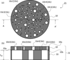
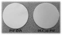
- FIG. 7 is a photograph of a porous PSF membrane / diamond-like carbon membrane two-layer bonded filter (Example 1-3). Since the metallic ring was used for fixing the porous PSF membrane, an exposed portion of the porous PSF membrane was formed. The white ring-shaped part is the exposed part of the porous PSF film, and the light yellow transparent film part is the diamond-like carbon film.
- FIG. 8 shows a low magnification image (a) of an electron micrograph showing the surface morphology of the porous PSF film, a high magnification image (b) thereof, and a diamond-like carbon film directly produced on the porous PSF film.
- a low-magnification image (c) and a high-magnification image (d) of an electron micrograph of a cross section of the two-layer bonded filtration filter are a low-magnification image (c) and a high-magnification image (d) of an electron micrograph of a cross section of the two-layer bonded filtration filter.
- the surface of the porous PSF membrane is smooth over a wide range, and does not include local protrusions of 50 nm or more in the range of at least 1 ⁇ m 2 . Further, the surface has pores in the range of 1 to 50 nm.
- a diamond-like carbon film is formed on the porous PSF film, all the pores in the range of 1 to 50 nm are covered with the diamond-like carbon film. Furthermore, it can be confirmed from the observation at a high magnification that the porous PSF film and the diamond-like carbon film are very well adhered.
- Thickness of the porous PSF film diamond-like carbon films deposited on the together the thickness of the deposited layer on a silicon substrate placed in the chamber by measuring the ellipsometric measurements was calculated.
- the thickness of each diamond-like carbon film was 10 nm (Example 1-1), 150 nm (Example 1-2), and 300 nm (Example 1-3), and it was confirmed that the thickness could be controlled by the deposition time. .
- Example 2 A porous PSF film / diamond-like carbon film two-layer bonded filter (Example 2-1) was produced in the same manner as in Example 1 except that the film formation temperature was set to ⁇ 20 ° C.
- Example 2-2 a two-layer bonded filter (Example 2-2) was produced in the same manner as in Example 2-1, except that the film formation time was 30 minutes.
- Example 2-3 a two-layer bonded filter (Example 2-3) was produced in the same manner as in Example 2-1, except that the film formation time was 60 minutes.
- each diamond-like carbon film was 10 nm (Example 2-1), 150 nm (Example 2-2), and 300 nm (Example 2-3).
- Table 2 shows the production conditions and thickness of the two-layer bonded filter (Examples 1-1 to 2-3).
- Example 1 the flux was evaluated under the suction condition of ⁇ 80 kPa.
- the ethanol flux was 3.5 L / m 2 h (two-layer bonded filter (Example 1-1)).
- the water flux was 2.2 L / m 2 h (two-layer bonded filtration filter (Example 1-1)).
- Table 3 summarizes the liquid permeation characteristic evaluation results and the viscosity ⁇ of the two-layer bonded filter (Example 1-1). As shown in Table 3, regarding the two-layer bonded filter (Example 1-1), the ethanol flux was larger than the water flux. From this, the flow path of the carbon film is considered to be a hydrophobic gap.
- Example 2 the evaluation of the flux was performed under the suction condition of ⁇ 80 kPa.
- the ethanol flux was 3.4 L / m 2 h (two-layer bonded filter (Example 2-3)).
- the water flux was 0.7 L / m 2 h (two-layer bonded filtration filter (Example 2-3)).
- the ethanol flux was greater than the water flux. From this, the flow path of the carbon film is considered to be a hydrophobic gap.
- Table 4 shows the results of evaluating the liquid permeation characteristics of the two-layer bonded filter (Example 1-1 and Example 2-3).
- n-hexane permeates three times faster than cyclohexane.
- the permeation rate of n-hexane is sufficiently large even in view of the effect of viscosity.
- the cause of the difference in the flux between n-hexane and cyclohexane may be due to the difference in pore size.
- the molecular width in the n-hexane all-trans conformation (the most stable conformation) is in the range of 0.42 nm to 0.45 nm.
- the molecular width in the cyclic conformation of cyclohexane (the most stable conformation) is in the range of 0.50 nm to 0.66 nm.
- Diamond-like carbon films identify such molecular sizes of solvent molecules and allow smaller ones to penetrate faster.
- the diamond-like carbon film of this example is considered to have a pore diameter of less than 0.42 nm. However, there is also a pore diameter of 0.42 nm or more and less than 0.66 nm that transmits n-hexane and blocks cyclohexane. Conceivable.
- n-Hexane is linear and cyclohexane is cyclic. In the case of a linear molecule, a part of its shape can be easily deformed, but in the case of a cyclic molecule, its shape is not easily deformed.
- FIG. 9 is a graph showing the separation characteristics of a diamond-like carbon membrane directly produced on a porous PSF membrane, and is an ultraviolet / visible absorption spectrum before and after filtration of a 0.5 mM ethanol solution of azobenzene.
- FIG. 9 shows an ultraviolet / visible absorption spectrum (1) of an ethanol solution (stock solution) of 0.5 mM azobenzene, and an ultraviolet / visible absorption of the filtrate when a two-layer joining type filter (Example 1-1) is used.
- Absorption spectrum (2) is shown.
- azobenzene molecular width: 0.69 nm
- the diamond-like carbon film of this example has a pore diameter of 0.66 nm or more and less than 0.80 nm because cyclohexane permeates at high speed and azobenzene is blocked 100%.
- FIG. 10 is a photograph showing the state of the membrane after conducting the azobenzene filtration experiment using the porous PSF membrane and the diamond-like carbon membrane directly produced on the porous PSF membrane.
- FIG. 10 shows photographs of the surfaces of a porous PSF membrane (Test Example 1) and a two-layer bonded filter (Example 1-1) after filtration of an ethanol solution of azobenzene.
- the porous PSF membrane Test Example 1
- the two-layer bonded filter Example 1-1
- azobenzene-derived coloration was observed, and azobenzene was separated from the filtrate (ethanol).
- FIG. 11 shows the separation characteristics of the porous PSF membrane, which are ultraviolet / visible absorption spectra before and after filtration of a 0.5 mM azobenzene / ethanol solution.
- FIG. 11 shows an ultraviolet / visible absorption spectrum (1) of an ethanol solution (stock solution) of 0.5 mM azobenzene and an ultraviolet / visible absorption spectrum of a filtrate when only a porous PSF membrane (Test Example 1) is used ( 2) is shown.
- the ultraviolet / visible absorption spectra of the stock solution and the filtrate overlapped. Thereby, it was found that the azobenzene could not be separated from the filtrate in the porous PSF membrane (Test Example 1). From the above, it can be concluded that the pore size of the diamond-like carbon film dominates the blocking performance, not the porous PSF film, in the two-layer bonded filtration filter (Example 1-1).
- the stock solution flux was 4 L / m 2 h when the two-layer bonded filter (Example 1-1) was used.
- the flux of the 0.5 mM azobenzene ethanol solution (stock solution) was almost the same as that of the ethanol solution, and even if azobenzene was present, the flux was not significantly changed.
- Table 6 shows the separation characteristic evaluation results of the two-layer bonded filtration filter (Example 1-1) and the porous PSF membrane (Test Example 1).
- the average of the width, height, and length of azobenzene molecules was 0.80 nm.
- the molecular width of azobenzene calculated from the molecular model is 0.69 nm
- the molecular length is 1.37 nm
- the molecular thickness is 0.33 nm.
- the average molecular size calculated from the length, width, and thickness of the azobenzene molecule is taken as a diameter corresponding to a sphere, it is 0.80 nm.
- Non-patent Document 4 describes the theory for calculating the pore diameter from the solute size and the rejection rate when the liquid flow in the pore has a parabolic velocity distribution.
- the azobenzene rejection was 99%, and (2) the pore diameter was 0.86 nm as a result of calculation assuming that the pores of the carbon film were cylindrical.
- the rejection of azobenzene was 100%, the pore size was 0.80 nm.
- a diamond-like carbon film manufactured using nanostrands as a sacrificial layer had a maximum inhibition rate of azobenzene of 95.2%.
- the diameter of the hole is estimated to be 0.95 nm from the sphere equivalent diameter (0.80 nm) using the Ferry-Renkin equation. That is, by using nanostrands as a sacrificial layer, it means that 0.95 nm or more pores that are considerably larger than the molecular size of azobenzene are formed inside the diamond-like carbon film.
- the rejection of azobenzene is 99% to 100%.
- the hole diameter estimated from the Ferry-Renkin equation is 0.86 nm with a 99% rejection and 0.80 nm with a 100% rejection.
- the rejection is 100%, there is a possibility that pores of less than 0.80 nm are formed, but it is not considered that pores of 0.8 nm or more are formed. This is because if there are pores of 0.8 nm or more, only a part of the azobenzene permeates the membrane and the rejection rate does not reach 100%.
- the removal rate is 100%, the average pore size inside the diamond-like carbon film is smaller than 0.8 nm.
- Non-Patent Document 2 and Patent Document 1 report a diamond-like carbon film having a high rejection with respect to azobenzene dissolved in an organic solvent. This researcher tried to produce an excellent filtration filter using the methods described in these documents. However, in the diamond-like carbon film manufactured using nanostrands as a sacrificial layer, the maximum blocking rate for azobenzene was 95.2%.
- ⁇ Separation characteristic evaluation 2 of porous PSF membrane / diamond-like carbon membrane two-layer bonded filter> A porous PSF film / diamond-like carbon film double-layered filtration filter having a diamond-like carbon film formed at ⁇ 20 ° C. using a 0.01 M NaCl aqueous solution (stock solution) as a stock solution (Example 2-1) ), The flux was measured under a suction condition of ⁇ 80 kPa, and the separation characteristics of the porous PSF membrane / diamond-like carbon membrane two-layer bonded filtration filter (Example 2-1) were examined.
- the refractive index of the stock solution and the filtrate was measured.
- the refractive index of the stock solution at 20 ° C. was 1.33306
- the refractive index of the filtrate at 20 ° C. was 1.333297.
- the NaCl concentration of the filtrate was estimated to be 0.00203M. Further, from this, the rejection rate of NaCl was 80%.
- the diamond-like carbon filter has RO (reverse osmosis) performance.
- Table 7 shows the results of the separation characteristic evaluation 2 of the two-layer bonded filter (Example 2-1).
- the water flux under a pressure of 2.4 MPa was 4.7 L / m 2 h, and the NaCl rejection was 68.5%. .
- the rejection of azobenzene was 95.2%, and it had pores of 0.95 nm or more.
- the flux of the two-layer bonded filter (Example 2-1) was 0.71 L / m 2 h (pressure difference: 80 kPa) despite the fact that the pressure difference before and after the membrane was 1/30. ).
- the NaCl rejection is also greatly improved to 80%. Further, it was confirmed that the two-layer bonded filter (Example 2-1) had an azobenzene rejection of 100% and had no pores of 0.80 nm or more.
- the hydrated ion diameter of sodium ions is estimated to be 0.72 nm, and the hydrated ion diameter of chloride ions is 0.66 nm.
- Example 3 In the formation of the diamond-like carbon film by the plasma CVD method, etching of the base material or chemical alteration may occur.
- a polymer ultrafiltration membrane is used as the porous support substrate, phenomena such as softening, melting, densification, and carbonization of the ultrafiltration membrane resulting from a local increase in temperature near the surface can be predicted.
- the separation functional layer is formed due to the alteration of the polymer.
- a diamond-like carbon self-supporting membrane is manufactured and transferred to a porous support substrate, thereby producing a filtration filter. The performance of was evaluated.
- a glucose film was formed on a support substrate such as silicon or glass, and a diamond-like carbon film was formed by plasma CVD. Thereafter, the glucose layer was eluted using pure water, and the diamond-like carbon film was peeled off as a free-standing film from the support substrate, and transferred onto the PSF ultrafiltration membrane. Also in the filtration filter manufactured in this way, 99% or more of the azobenzene rejection was confirmed, and it was proved that the diamond-like carbon film worked as a separation functional layer of azobenzene.
- the specific procedure is as follows.
- a silicon support substrate was prepared.
- a glucose film was produced as an intermediate layer on the support substrate by spin coating.
- a diamond-like carbon film was formed on the intermediate layer by plasma CVD.
- pure water was used to elute only the intermediate layer, and the DLC film was peeled from the support substrate. Note that a thin hydrofluoric acid aqueous solution may be used instead of pure water.
- the peeled DLC film peeleling transfer diamond-like carbon film
- FIG. 12 is a photograph showing the state of the porous PSF film and the surface of the porous PSF film obtained by transferring the diamond-like carbon film to the surface.
- FIG. 12 shows a photograph of only a porous PSF film and a photograph of a filtration filter (Example 3-1) in which a release transfer diamond-like carbon film is disposed on the porous PSF film.
- a filtration filter (Example 3-2) was produced in the same manner as in Example 3-1, except that a sucrose membrane was used as the intermediate layer.
- a filtration filter (Example 3-3) was produced in the same manner as in Example 3-1, except that a glucose / sucrose mixture membrane was used as the intermediate layer.
- a filtration filter (Example 3-4) was produced in the same manner as in Example 3-1, except that a glycerin membrane was used as the intermediate layer.
- a filtration filter (Example 3-5) was produced in the same manner as in Example 3-1, except that a polyethylene glycol membrane was used as the intermediate layer.
- Example 3-6 a filtration filter (Example 3-6) was produced in the same manner as in Example 3-1, using a thin aqueous hydrofluoric acid solution.
- Example 3-7 When glass was used as the support substrate, a filtration filter (Example 3-7) was prepared in the same manner as in Example 3-1, using a thin aqueous hydrofluoric acid solution.
- Example 4 A filtration filter in which a release transfer diamond-like carbon film is disposed on a porous alumina film in the same manner as in Example 3-1, except that a porous alumina film is used instead of the porous PSF film (Example 4-1) was made.
- FIG. 13 is a graph showing the separation characteristics of the diamond-like carbon membrane transferred onto the porous PSF membrane, and is an ultraviolet / visible absorption spectrum before and after filtration of a 0.5 mM ethanol solution of azobenzene.
- FIG. 13 shows an ultraviolet / visible absorption spectrum (1) of an ethanol solution (stock solution) of 0.5 mM azobenzene and an ultraviolet / visible absorption spectrum (2) of the filtrate when a filtration filter (Example 3-1) is used. )It is shown.
- the filtration filter (Example 3-1) could block 99% of azobenzene (molecular weight: 182.2, molecular width: 0.69 nm).
- the stock solution flux was 2 L / m 2 h.
- Table 8 shows production conditions and thicknesses of the filtration filters (Examples 3-1 to 3-7, 4-1, 4-2).
- Table 9 shows the results of the separation characteristic evaluation of the filtration filter (Example 3-1).
- Example 5 The porous PSF film produced in Test Example 1-1 was placed in the chamber of the sputtering apparatus. Next, after reducing the pressure in the chamber, argon and methane are introduced at a predetermined flow rate (argon: 120 mL / min, methane: 12 mL / min) to form a mixed gas atmosphere, and the pressure in the chamber is further reduced to 0.5 Pa or less. It was. A diamond-like carbon film was directly formed on the porous PSF film by magnetron sputtering to produce a porous PSF film / diamond-like carbon film two-layer bonded filter (Example 5-1). The film formation time was 77 min.
- Example 5-2 a two-layer bonded filtration filter (Example 5-2) was produced under the same conditions as in Example 4-1, except that the film formation time was 39 minutes.
- Example 6 The porous PSF film produced in Test Example 1-1 was placed in the chamber of the sputtering apparatus. Next, argon gas was introduced into the chamber at a predetermined flow rate (10 mL / min), and the pressure in the chamber was set to 0.7 Pa or less. A diamond-like carbon film was formed directly on the porous PSF film by magnetron sputtering to produce a porous PSF film / diamond-like carbon film two-layer bonded filter (Example 6-1). The film formation time was 72 minutes.
- Example 6-2 a film formation time was set to 36 min, and the other conditions were the same as in Example 6-1 to prepare a two-layer bonded filter (Example 6-2).
- Example 7 The porous PSF film produced in Test Example 1-1 was placed in the chamber of the sputtering apparatus. The pressure during film formation was set to 0.1 Pa or less without introducing gas into the chamber. An arc ion plating method, which is one of the sputtering methods, is used to deposit diamond-like carbon directly on a porous PSF film, and a porous PSF film / diamond-like carbon film two-layer bonded filter (Example) 7-1) was produced. The film formation time was 15 min.
- Example 7-2 a two-layer bonded filtration filter (Example 7-2) was produced under the same conditions as in Example 7-1 except that the film formation time was 7 minutes.
- the thickness of the diamond-like carbon film is controlled by adjusting the film formation time.
- the film thickness in Example 5-1, Example 6-1 and Example 7-1 is 100 nm, and the film thickness in Example 5-2, Example 6-2 and Example 7-2 is 50 nm.
- the film forming speed in these examples is 8 nm / min or less.
- FIG. 14 shows a low-magnification image (a) of an electron micrograph of a cross-section of a diamond-like carbon film two-layer bonded filtration filter (Example 6-1) directly produced on a porous PSF film by sputtering, and its high It is a magnification image (b).
- a diamond-like carbon film is sputtered on the porous PSF film, one side of the porous PSF film is entirely covered with diamond-like carbon. Furthermore, it can be confirmed from the observation at a high magnification that the porous PSF film and the diamond-like carbon are in very good contact.
- Table 10 shows the film forming conditions and film thicknesses of the diamond-like carbon films (DLC film, DLC is an acronym for Diamond-Like Carbon) in Examples 5 to 7.
- FIG. 15 is a graph showing the separation characteristics of a diamond-like carbon film directly produced on a porous PSF film by sputtering, and is an ultraviolet / visible absorption spectrum before and after filtration of a 0.5 mM ethanol solution of azobenzene.
- FIG. 15 shows an ultraviolet / visible absorption spectrum (1) of an ethanol solution (stock solution) of 0.5 mM azobenzene, and an ultraviolet / visible absorption of the filtrate when a two-layer joining type filtration filter (Example 5-1) is used.
- Absorption spectrum (2) is shown. As shown in FIG.
- azobenzene (molecular weight: 182.2, molecular width: 0.69 nm) could be blocked by 99% or more in the two-layer bonded filtration filter (Example 5-1). It can be confirmed that the diamond-like carbon film of this example has a pore diameter of less than 0.86 nm. Table 11 shows the evaluation results of the separation characteristics of the two-layer bonded filter (Example 5-1).
- the concentration of NaCl in the stock solution and the filtrate was quantified from the refractive index.
- the refractive index of the stock solution at 20 ° C. was 1.333306
- the refractive index of the filtrate at 20 ° C. was 1.33396. From the latter value, the NaCl concentration of the filtrate was estimated to be 0.00102M.
- the NaCl rejection was calculated to be 90% from changes in the concentration of the stock solution and the filtrate.
- the calculated osmotic pressure of a 0.01 M NaCl aqueous solution (stock solution) at 25 ° C. is 49 kPa.
- suction filtration is performed at ⁇ 80 kPa, and the pressure difference (filtration driving force) obtained by subtracting the osmotic pressure is calculated as ⁇ 31 kPa.
- the filtrate flux was 1.05 L / m 2 h.
- Table 12 shows the separation characteristic evaluation results of the two-layer bonded filtration filter of Example 5-1.
- NF or RO membrane made of hard carbon membrane of the present invention filtration filter, two-layer joining type filtration filter and production method thereof have oil resistance, and a filtration filter capable of separating 99% or more of azobenzene dye in an organic solvent
- the production method can be provided and can be used in the treatment of wastewater containing organic solvents, the treatment of petroleum-associated water, the production of high-purity solvents, the food industry, and the like.
- the two-layer bonded filter is formed on an ultrafiltration membrane having pores of 50 nm or less on the surface even if the thickness of the hard carbon membrane NF or RO membrane is 100 nm or less.
- the mechanical strength can be increased while realizing the permeability, and the pressure resistance and durability of the filtration membrane can be improved.
- the NF or RO membrane made of a hard carbon membrane is formed on the flexible ultrafiltration membrane, the processing into the filtration module is easy. That is, it can be used as an NF or RO membrane having a high filtration rate and high durability. Moreover, since the removal rate of sodium chloride can be controlled at 80% or more, it has high convenience as an organic solvent-resistant NF membrane.
Landscapes
- Chemical & Material Sciences (AREA)
- Chemical Kinetics & Catalysis (AREA)
- Inorganic Chemistry (AREA)
- Engineering & Computer Science (AREA)
- Water Supply & Treatment (AREA)
- Manufacturing & Machinery (AREA)
- Separation Using Semi-Permeable Membranes (AREA)
- Nanotechnology (AREA)
- Carbon And Carbon Compounds (AREA)
- Physical Vapour Deposition (AREA)
- Chemical Vapour Deposition (AREA)
Abstract
Description
ナノストランドそのものは、極細の無機ファイバーであり、これを濾過することで形成されるナノストランド層は、非常に緻密であり、10nm以下の孔を有するために、それ自身が濾過フィルターとして利用できる(特許文献2)。
さらに、ナノストランドを犠牲層として用いた場合、プラズマCVDなどの方法によりダイヤモンド状カーボンを蒸着させると、蒸着の過程でナノストランドの一部がエッチングされ、犠牲層の表面近傍でのプラズマの組成が変化してしまう。これにより、ダイヤモンド状カーボン膜の内部には、一部に0.95nm以上の大きさの孔が形成されてしまう。また、ナノストランドを犠牲層として製造したダイヤモンド状カーボン膜では、膜の一面にナノストランドを除去することでファイバー状のナノストランドの除去痕が形成されている(非特許文献2)。この除去痕の存在は、多孔性支持基板として用いた精密濾過膜との接着性を低下させ、圧力を負荷した場合にダイヤモンド状カーボン層の内部に1nm以上の大きさの孔(欠陥)を生じさせやすい。これらの影響は、形成されるダイヤモンド状カーボン膜の厚みが100nm以下の場合に大きく、35nm以下の場合に特に大きい。
このような理由により、ダイヤモンド状カーボン膜の品質は、ナノストランドの犠牲層により大きく低下する。
その結果、表面に50nm以下の大きさの孔を有する限外濾過膜を用いることで、ナノストランド層を犠牲層とした場合では達成できない0.86nm以上の大きさの孔を有しないダイヤモンド状カーボン膜を製造することに成功した。さらに、適切な条件下では、0.8nm以上の大きさの孔を有しないダイヤモンド状カーボン膜を製造することにも成功した。
すなわち、まず、上記の0.86nm以上の大きさの、さらには0.8nm以上の大きさの孔を有しないダイヤモンド状カーボン膜を得るためには、表面が平滑な基材を利用することである。表面の孔(あるいは凹凸)が50nm以下である基材であれば、優れた阻止性能のダイヤモンド状カーボン膜を製造することができる。例えば、糖のスピンコート膜は、表面が非常に平滑な膜を与えるが、この膜の表面にダイヤモンド状カーボンを蒸着することによっても、0.86nm以上の孔を有しないダイヤモンド状カーボン膜を製造することができる。また、このようなダイヤモンド状カーボン膜は、分離膜としての性能を損なわずに、多孔性の基材に移し取る(転写する)ことが可能である。
以上の知見とこれに関する一般的な技術的前提を踏まえ、本発明は、以下の構成を有するものとして特徴づけられる。
(2)硬質カーボン膜からなり、厚みが5nm以上300nm以下であり、有機溶媒中のアゾベンゼン色素を99%以上通過させないことを特徴とする硬質カーボン膜製NF又はRO膜。
(3)有機溶媒耐性であることを特徴とする上記(1)(2)の硬質カーボン膜製NF又はRO膜。
(4)硬質カーボン膜からなり、厚みが5nm以上300nm以下であり、水中のNaClを80%以上通過させないことを特徴とする硬質カーボン膜製NF又はRO膜。
(5)前記硬質カーボン膜がダイヤモンド状カーボン膜であることを特徴とする上記(1)から(4)の硬質カーボン膜製NF又はRO膜。
(7)上記(1)から(5)のいずれかの硬質カーボン膜製NF又はRO膜が限外濾過膜の一面に接合されている2層接合型濾過フィルターであって、前記限外濾過膜が表面に1μm2の範囲で50nm以上の局所的な凸部を含まず、表面の孔径が1nm以上50nm以下とされていることを特徴とする2層接合型濾過フィルター。
(9)前記多孔性有機膜がポリスルホン(PSF)膜であることを特徴とする上記(8)の2層接合型濾過フィルター。
(12)前記支持基板がシリコン又はガラスであることを特徴とする硬質カーボン膜製NF又はRO膜の製造方法。
まず、本発明の実施形態である硬質カーボン膜製NF又はRO膜について説明する。
図1は、本発明の実施形態である硬質カーボン膜製NF又はRO膜の一例を示す概略説明図である。通常、硬質カーボン膜製NF又はRO膜の表面には、様々な平面視形状の孔が形成され、貫通形状も円筒状に限られるものではないが、図1では、説明のため、孔を均質な円筒状で簡略化して示している。
硬質カーボン膜製NF又はRO膜10は、例えば、ダイヤモンド状カーボン(DLC)からなるNF又はRO膜である。硬質カーボン膜は透明性が高い膜であり、その一例であるダイヤモンド状カーボン膜も透明性が高い膜である。図1に示すように、硬質カーボン膜製NF又はRO膜10は、厚みt10が5nm以上300nm以下であり、複数の孔10cが設けられた多孔質膜である。
製造条件を制御することにより、より小さな孔をもつ硬質カーボン膜として、0.80nm未満の孔径をもつ膜を製造することもできる。
孔10c1は0.42nm未満の孔径d1を有するグループであり、孔10c2は0.42nm以上0.66nm未満の孔径d2を有するグループであり、孔10c3は0.66nm以上0.80nm未満の孔径d3を有するグループであり、孔10c4は0.80nm以上0.86nm未満の孔径d4を有するグループである。例えばこのような孔径d1、d2、d3、d4の大きさのグループ区分により、対応する大きさの分子を選択分離することができる。
なお、孔の最大径は0.86nm未満とされている。
また、硬質カーボン膜製NF又はRO膜を有する濾過フィルターは、その基材として有機溶媒耐性の限外濾過膜を選択することで、多くの有機溶媒に対して優れた耐性を有する濾過フィルターとなる。
次に、本発明の実施形態である濾過フィルターについて説明する。
図2は、本発明の実施形態である濾過フィルターの一例を示す概略説明図である。
図2に示すように、本発明の実施形態である濾過フィルター21は、本発明の実施形態である硬質カーボン膜製NF又はRO膜10が多孔性支持基板20の一面20a上に配置されている。
多孔性支持基板20としては、多孔性有機膜、多孔性無機膜又は多孔性金属膜のいずれか一の多孔性膜を挙げることができる。具体的には、例えば、多孔性ポリスルホン(PSF)膜、多孔性アルミナ膜、多孔性アルミ膜を挙げることができる。
多孔性支持基板20の厚みt20は5μm以上100μm以下が好ましい。また、多孔性支持基板20は、ポリエステルやポリプロピレン、セルロース等の柔軟な不織布の上に形成されているものを用いてもよい。これにより、非常にフレキシブルな濾過フィルターを形成でき、モジュールの製造にも好適に利用できる。
次に、本発明の実施形態である2層接合型濾過フィルターについて説明する。
図3は、本発明の実施形態である2層接合型濾過フィルターの一例を示す概略説明図である。
図3に示すように、本発明の実施形態である2層接合型濾過フィルター31は、本発明の実施形態である硬質カーボン膜製NF又はRO膜10が限外濾過膜30の一面30aに接合されている。限外濾過膜30の一面30aは硬質カーボン膜製NF又はRO膜10との接合面とされている。
一般に、限外濾過膜を濾過フィルターとして利用する場合、阻止率は膜の表面及び内部の孔によって決定する。この阻止率に基づく孔の範囲は、IUPACの定義によると1nmから100nmの範囲にある。
なお、本発明での限外濾過膜30の孔径は、硬質カーボン膜製NF又はRO膜10の接合面(および接合面から50nmの範囲)での孔のことであり、その円相当の直径のことである。限外濾過膜では、その製造法の如何により、内部に50nm以上の細孔が形成され、場合によっては1μm以上の孔が形成される。このような場合でも、前記接合面(および接合面から50nmの範囲)での孔径が50nm以下であれば好ましく、限外濾過膜30の内部(および接合面とは異なる一面)に大きな孔が形成されていても特に問題はない。
なお、本発明での硬質カーボン膜製NF又はRO膜の孔径は、その阻止性能に基づいて評価された孔径のことを言う。即ち、本発明の硬質カーボン膜製NF又はRO膜には、阻止率に影響を与えないのであれば、最大孔径としては、0.86nm以上の部分が含まれていてもよい。
次に、本発明の実施形態である硬質カーボン膜製NF又はRO膜の製造方法について説明する。
本発明の実施形態である硬質カーボン膜製NF又はRO膜の製造方法は、中間層形成工程S1と、硬質カーボン膜成膜工程S2と、硬質カーボン膜剥離工程S3とを含む。
この工程では、支持基板の一面に、例えば、スピンコーティング法、キャスト法、ディッピング法、又はダイコート法により中間層を形成する。
前記支持基板としては、シリコン又はガラスを好適なものとして挙げることができる。平滑面を有するこれらの支持基板を用いることにより、平滑な中間層を形成できる。
前記中間層としては、例えば好適なものとして、グルコース、スクロース、グルコース/スクロース混合物、グリセリン、ポリエチレングリコール、シリコン熱酸化膜の群から選択されるいずれか一の材料からなる膜を挙げることができる。これらの材料を用いることにより、中間層に、表面に1μm2の範囲で50nm以上の局所的な凸部を含まない平滑面を形成できる。
この工程では、前記中間層を形成した支持基板を真空チャンバー内に配置し、前記真空チャンバー内を減圧状態とし、前記支持基板を-20℃以上30℃以下の温度としてから、プラズマCVD法又はスパッタ法により、50nm/min以下の成膜速度で、前記中間層の一面に硬質カーボン膜を成膜する。
高周波プラズマ装置は、チャンバーと、配管と、電極部と、ガス導入管と、を有するものとして概略構成されている。なお、上下の電極部は、一対の電極部として機能し、その間に電界を印加できる構成とされている。下の電極部は、基板を保持する機能を併せ持つ。配管は、ガス供給部(図示略)に接続されており、ガス供給部に貯蔵されたガスをチャンバー内に導入するガス導入管として用いられる。配管は、真空ポンプと接続されており、チャンバー内を所定の真空度に減圧可能とするとともに、チャンバー内に導入したガスを排出するガス排出管としても用いられる。
前記有機化合物は、室温の前後10℃の範囲内における蒸気圧が8Pa以上である有機化合物であることが好ましい。前記有機化合物は、炭化水素だけでなく、酸素、窒素、硅素、リン、ホウ素、その他の元素を含むものであってよい。
前記有機化合物はガス状態とした後、単体のガスとしてチャンバー内に導入してもよく、また、他の有機化合物や不活性ガスとの混合ガスとしてチャンバー内に導入してもよい。例えば、アセチレンやブタジエンなどの反応性が高いガスはアルゴンガスと混合して導入することが好ましい。
また、有機化合物や成膜条件を選択することで、細孔サイズや力学的性質、化学的性質が異なる硬質カーボン膜が得られるため、前記異なる硬質カーボン膜を積層させることによって、濾過フィルターとしての性質を制御することが可能となる。
なお、ヘキサメチルジシロキサンなどの沸点が比較的高い液体を用いる場合、チャンバーの外部に前記液体をガス化するための減圧容器を設け、前記減圧容器で圧力8Pa以上のガスとしてからチャンバー内に導入してもよい。
スパッタ装置は、チャンバーと、配管と、ターゲット部を有するものとして概略構成されている。また、スパッタの様式としては、アーク放電法、マグネトロン法、イオンアシスト法などがあり、これらを単独又は組み合わせて用いてよい。ターゲットは、一般にはアモルファスカーボン又はグラファイトが用いられるが、炭素原子だけでなく、リンやホウ素、酸素、窒素、ケイ素などの異元素を含んでいてもよい。さらに、ターゲットから放出する原子、イオン、クラスター、プラズマ等の濃度や組成、温度等を調整するために、チャンバー内にはアルゴン等の不活性ガスやメタン、エタン、ピリジン等のガス状の有機物を導入してもよい。スパッタによって生じるイオン化した原子や分子、クラスターは、電界等を用いて支持基板に誘導することもできる。これらの方法は、スパッタ法の一般的な手法として広く知られている。
成膜条件は、基板温度-20℃以上30℃以下、50nm/min以下の成膜速度とする。前記成膜条件とすることにより、硬質カーボン膜の平滑性を高めることができ、硬質カーボン膜の孔径を0.86nm未満にできる。
その他の成膜条件は、特に限定する訳ではないが、例えば、出力2~100W、圧力1~8Pa、成膜時間1~3600秒の範囲とする。前記成膜条件とすることにより、有機化合物を含むガスをプラズマ化し、厚みが5nm以上300nm以下の硬質カーボン膜を成膜することができる。
その他の成膜条件は、特に限定する訳ではないが、圧力は1Pa以下が望ましく、成膜時間は、1~7200秒の範囲が望ましい。前記成膜条件とすることにより、厚みが5nm以上300nm以下の硬質カーボン膜を成膜することができる。
この工程では、前記硬質カーボン膜を成膜した支持基板を、水又は酸水溶液に浸漬して、中間層を溶出し、前記支持基板から硬質カーボン膜製NF又はRO膜を剥離する。
次に、本発明の実施形態である濾過フィルターの製造方法について説明する。
本発明の実施形態である濾過フィルターの製造方法は、先に記載の硬質カーボン膜製NF又はRO膜の製造方法で製造した硬質カーボン膜を、多孔性有機膜、多孔性無機膜又は多孔性金属膜のいずれか一の多孔性膜からなる多孔性支持基板の一面上に配置して、濾過フィルターを製造する。
水又は酸水溶液中で、先に記載の硬質カーボン膜製NF又はRO膜の製造方法で剥離した硬質カーボン膜製NF又はRO膜を静かに多孔性支持基板の一面上に配置することにより、濾過フィルターを容易に製造できる。
次に、本発明の実施形態である2層接合型濾過フィルターの製造方法について説明する。
本発明の実施形態である2層接合型濾過フィルターの製造方法は、前処理工程S11と、硬質カーボン膜成膜工程S12と、を有する。
この工程では、表面に1μm2の範囲で50nm以上の局所的な凸部を含まず、表面の孔径が1nm以上50nm以下の限外濾過膜を調製後、有機溶媒洗浄と真空乾燥処理を行い、限外濾過膜の前処理を行う。
この工程では、前記前処理した限外濾過膜を、真空チャンバー内に配置し、前記真空チャンバー内を減圧状態とし、前記前処理した限外濾過膜を-20℃以上30℃以下の温度としてから、50nm/min以下の成膜速度で、プラズマCVD法又はスパッタ法により、前記前処理した限外濾過膜の一面に硬質カーボン膜を成膜する。
その他の成膜条件には、前記硬質カーボン膜成膜工程S2と同様な条件を選択することができる。
硬質カーボン膜製NF又はRO膜10の孔10cの孔径は0.86nm未満とされている。これにより、図4に示すように、分子サイズ0.80nmのアゾベンゼン色素は硬質カーボン膜製NF又はRO膜10を透過できず、99%以上を溶媒から分離できる。
硬質カーボン膜製NF又はRO膜10の孔10cの孔径は0.86nm未満とされている。これにより、図5に示すように、分子サイズ0.80nmのアゾベンゼン色素は硬質カーボン膜製NF又はRO膜10を透過できず、99%以上を溶媒から分離できる。
図6に示すように、硬質カーボン膜製NF又はRO膜10の孔10cは先に記載したように孔径によりグループ分けされている。これにより、ほぼ同様な立体構造を有する有機溶媒を透過させたときに、分子サイズの違いによって、流束(フラックス)の違いを生じさせる。
本発明の実施形態の具体例を以下の実施例で示す。もちろん、本発明はこれらの実施例に限定されるものではない。
<多孔性PSF膜の作製>
まず、ポリスルホン(PSF)(ソルベイアドバンストポリマーズ社製 ユーデル ポリサルホン P-1700)7.5gを、N,N-ジメチルアセトアミド(和光純薬社製 特級)42.5gに加えてから、6時間室温で撹拌して、高分子濃度15wt%のキャスト溶液を作製した。
次に、このキャスト溶液を5分間真空で保持して脱泡処理を行なった後、シリコン基板(2インチ)上に滴下してから、回転数2000rpmで2秒間スピンコートして、均一に塗布した。
次に、この基板をすばやく室温下の純水に浸漬して、非溶媒誘起相分離法により、カーボン濾過フィルターの基材となるフレキシブルなポリスルホンの多孔性シート(多孔性PSF膜)(試験例1-1)を作製した。
続いて、同条件で試験例1-2、試験例1-3の多孔性PSF膜も作製した。
多孔性PSF膜を介した水の流束は、-80kPaの吸引条件で2300L/m2hであり、複数の透過実験を行った場合の標準偏差は350L/m2hであった(試験例1-1)。
また、屈折率計を用いて分画分子量の測定を行った。デキストランを用いて評価した多孔性PSF膜の分画分子量は200k(試験例1-1)、190k(試験例1-2)、210k(試験例1-3)であった。
また、多孔性PSF膜の厚みは20μm(試験例1-1)、15μm(試験例1-2)、25μm(試験例1-3)であった。
表1は、多孔性PSF膜(試験例1-1~1-3)の評価結果である。

<多孔性PSF膜/ダイヤモンド状カーボン膜の2層接合型濾過フィルターの作製1>
まず、プラズマCVD装置のチャンバー内の所定の位置に、試験例1-1で作製した多孔性PSF膜を配置した。
次に、チャンバー内を減圧してから、プロピルアミンを原料ガスとして、成膜温度を室温(25℃)とし、プラズマCVD法に基づき、成膜時間を2分として、多孔性PSF膜上に直接、ダイヤモンド状カーボンを堆積させて、多孔性PSF膜/ダイヤモンド状カーボン膜の2層接合型濾過フィルター(実施例1-1)を作製した。
また、図8は、多孔性PSF膜の表面形態を示した電子顕微鏡写真の低倍率像(a)と、その高倍率像(b)と、多孔性PSF膜上に直接作製したダイヤモンド状カーボン膜の2層接合型濾過フィルター断面の電子顕微鏡写真の低倍率像(c)と、その高倍率像(d)である。
多孔性PSF膜の表面は、広範囲に渡って平滑であり、少なくとも1μm2の範囲には、50nm以上の局所的な凸部を含まない。また、その表面には、1~50nmの範囲の細孔を有する。多孔性PSF膜上にダイヤモンド状カーボン膜を成膜すると、上記の1~50nmの範囲の細孔は、全てダイヤモンド状カーボン膜で覆われる。さらに、高倍率の観察から、多孔性PSF膜とダイヤモンド状カーボン膜は非常に良く密着していることが確認できる。
各ダイヤモンド状カーボン膜の厚みは、10nm(実施例1-1)、150nm(実施例1-2)、300nm(実施例1-3)であり、堆積時間によって、厚みをコントロールできることが確認できた。
成膜温度を-20℃とした他は実施例1と同様にして、多孔性PSF膜/ダイヤモンド状カーボン膜の2層接合型濾過フィルター(実施例2-1)を作製した。
表2は、2層接合型濾過フィルター(実施例1-1~2-3)の作製条件及び厚みである。

動的粘弾性測定法を用いて、150nm(実施例1-2に対応)、300nm(実施例1-3に対応)のダイヤモンド状カーボン膜のヤング率を測定した結果、それぞれ58.3GPa、58.9GPaであった。この結果は、本実施例の製膜法で、ダイヤモンド状カーボン膜(又は硬質カーボン膜)が形成されていることを示している。
従来の高性能のNF又はRO膜は、ヤング率が5GPa以下の架橋ポリマーやエンジニアリングプラスチックから製造されており、本実施例の膜は、これと比較して約10倍硬質である。
次に、多孔性PSF膜/ダイヤモンド状カーボン膜の2層接合型濾過フィルター(実施例1-1及び実施例2-3)の液体透過特性を検討した。
多孔性PSF膜/ダイヤモンド状カーボン膜の2層接合型濾過フィルター(実施例1-1及び実施例2-3)はいずれも、有機溶媒(エタノール)及び水のどちらも透過させた。
エタノールのフラックスは、3.5L/m2h(2層接合型濾過フィルター(実施例1-1))であった。
一方、水の流束は2.2L/m2h(2層接合型濾過フィルター(実施例1-1))であった。
表3は、2層接合型濾過フィルター(実施例1-1)の液体透過特性評価結果及び粘度ηをまとめたものである。
表3に示すように、2層接合型濾過フィルター(実施例1-1)に関しては、エタノールの流束が、水の流束と比較して大きかった。これから、カーボン膜の流路は疎水性の隙間と考えられる。

エタノールのフラックスは、3.4L/m2h(2層接合型濾過フィルター(実施例2-3))であった。
一方、水の流束は、0.7L/m2h(2層接合型濾過フィルター(実施例2-3))であった。
実施例2に関しても、エタノールの流束が、水の流束と比較して大きかった。これから、カーボン膜の流路は疎水性の隙間と考えられる。
表4は、2層接合型濾過フィルター(実施例1-1及び実施例2-3)の液体透過特性評価結果である。

分子サイズの異なるアルカン(n-ヘキサン、n-へプタン、n-オクタン、n-デカン、シクロヘキサン)を原液として用いて、多孔性PSF膜/ダイヤモンド状カーボン膜の2層接合型濾過フィルター(実施例1-1)で濾過して、-80kPaの吸引条件で流束を測定して、多孔性PSF膜/ダイヤモンド状カーボン膜の2層接合型濾過フィルター(実施例1-1)の透過特性を検討した。
表5は、多孔性PSF膜/ダイヤモンド状カーボン膜の2層接合型濾過フィルター(実施例1-1)で濾過したときの各液体の流束及び粘度ηをまとめたものである。

n-ヘキサンの粘度は、0.295mPa・sであり、シクロヘキサンの粘度は0.887mPa・sである。ダイヤモンド状カーボン膜を介した液体の透過は、ダルシーの法則に従うものと考えられ、粘度の違いから、n-ヘキサンがシクロヘキサンより3倍速く透過すると言える。しかしながら、n-ヘキサンの透過速度は、粘度の影響を鑑みても十分に大きい。
次に、多孔性PSF膜/ダイヤモンド状カーボン膜の2層接合型濾過フィルター(実施例1-1)の分離特性を検討した。なお、比較のために、多孔性支持基板として用いた多孔性PSF膜(試験例1)の分離特性も検討した。
具体的には、0.5mMのアゾベンゼンのエタノール溶液(原液)を-80kPaの吸引条件で濾過して、フィルター表面上の固形物と濾液とに分離した。フィルター表面上の表面観察をするとともに、濾液の紫外/可視吸収スペクトルを測定した。
図10に示すように、多孔性PSF膜(試験例1)では、アゾベンゼン由来の着色が見られず、アゾベンゼンは吸着されず、アゾベンゼンは分離できなかった。
一方、2層接合型濾過フィルター(実施例1-1)では、アゾベンゼン由来の着色が見られ、アゾベンゼンが濾過液(エタノール)と分離された。
以上により、2層接合型濾過フィルター(実施例1-1)では、多孔性PSF膜ではなく、ダイヤモンド状カーボン膜の孔径が阻止性能を支配したと結論できる。
表6は、2層接合型濾過フィルター(実施例1-1)及び多孔性PSF膜(試験例1)の分離特性評価結果である。

n-ヘキサン、シクロヘキサンの分子サイズおよびアゾベンゼンのサイズと阻止率から多孔性PSF膜/ダイヤモンド状カーボン膜の2層接合型濾過フィルター(実施例1-1)のダイヤモンド状カーボン膜の孔径を算出した。
有機分子のサイズには、様々な捉え方があるが、分子モデルから算出されるアゾベンゼンの分子幅は0.69nmであり、分子長は1.37nm、分子厚みは0.33nmとなる。また、アゾベンゼン分子の長さ、幅、厚みから計算される平均分子サイズを球相当の直径として捉えると0.80nmとなる。
また、アゾベンゼンの阻止率を100%とした場合には、孔径が0.80nmとなった。
除去率が100%の場合、ダイヤモンド状カーボン膜の内部の平均的な孔のサイズは、0.8nmより小さい。
非特許文献2や特許文献1では、有機溶媒に溶解したアゾベンゼンに対して高い阻止率を有するダイヤモンド状カーボン膜が報告されている。本研究者は、これらの文献に記載された方法を用いて、優れた濾過フィルターを製造することを試みた。しかしながら、ナノストランドを犠牲層として製造したダイヤモンド状カーボン膜では、アゾベンゼンに対する阻止率が最大95.2%であった。
0.01MのNaCl水溶液(原液)を原液として用いて、-20℃で成膜したダイヤモンド状カーボン膜を有する多孔性PSF膜/ダイヤモンド状カーボン膜の2層接合型濾過フィルター(実施例2-1)で濾過して、-80kPaの吸引条件で流束を測定して、多孔性PSF膜/ダイヤモンド状カーボン膜の2層接合型濾過フィルター(実施例2-1)の分離特性を、検討した。
原液の20℃における屈折率は1.33306であり、濾液の20℃における屈折率は1.33297であった。
濾液の屈折率から、濾液のNaCl濃度は0.00203Mと見積もられた。
また、これから、NaClの阻止率は80%となった。
さらに、流束は0.71L/m2hであった。
以上の結果から、ダイヤモンド状カーボンの濾過フィルターはRO(逆浸透)性能を有していた。
表7は、2層接合型濾過フィルター(実施例2-1)の分離特性評価2の結果である。
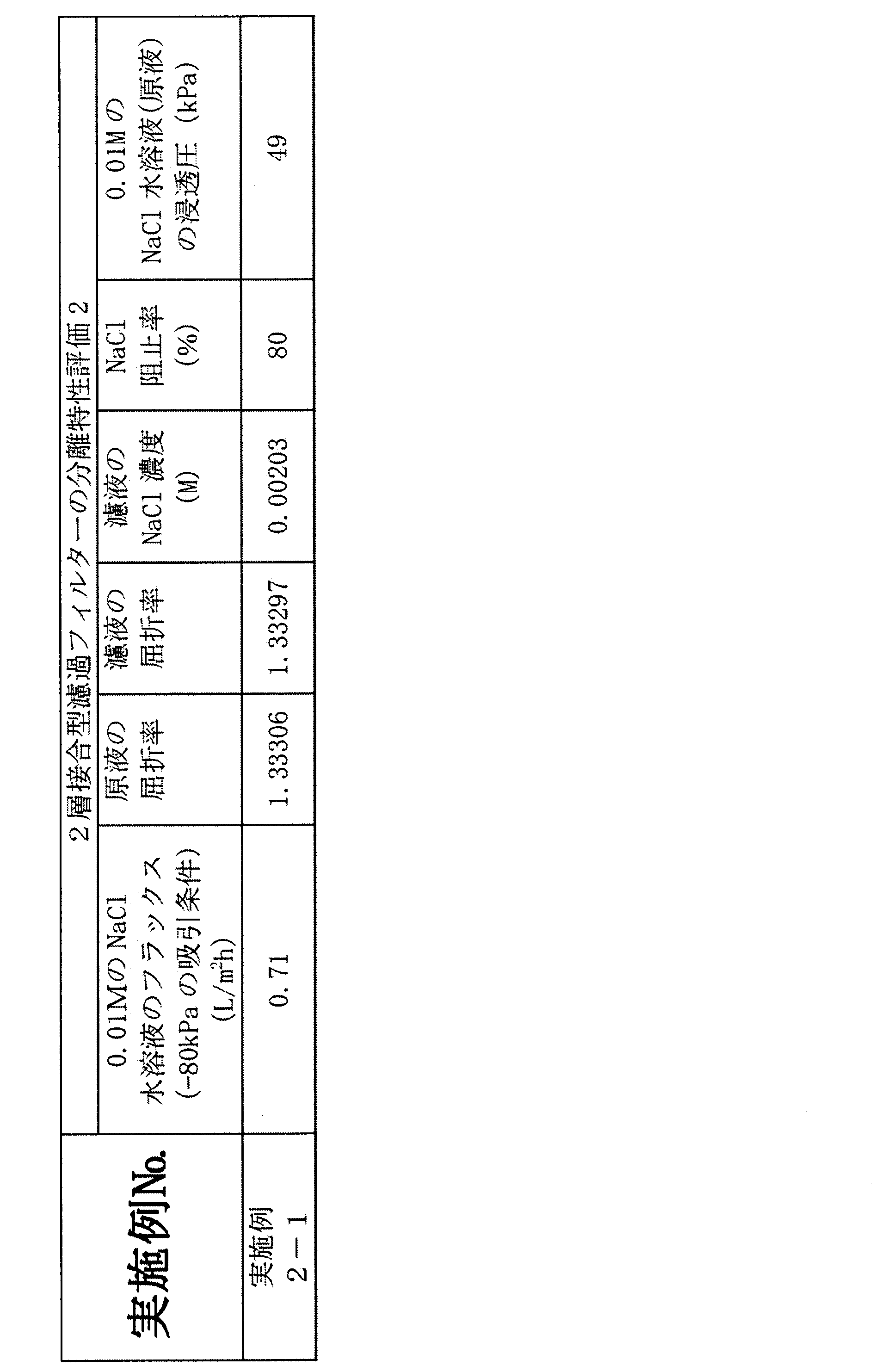
それに対し、2層接合型濾過フィルター(実施例2-1)のフラックスは、膜の前後の圧力差が30分の1であるにもかかわらず、0.71L/m2h(圧力差:80kPa)という流束を有する。NaCl阻止率も80%と大いに向上している。さらに、2層接合型濾過フィルター(実施例2-1)では、アゾベンゼンの阻止率が100%であり、0.80nm以上の細孔を有しないことが確認された。
プラズマCVD法によるダイヤモンド状カーボン膜の形成では、基材のエッチングや化学的な変質が起こりえる。多孔性支持基板として高分子の限外濾過膜を用いた場合、表面近傍の局所的な温度の上昇に由来する限外濾過膜の軟化、溶融、緻密化、炭化などの現象も予測でき、このような高分子の変質により分離機能層が形成されている可能性がある。
そこでは、最外層のダイヤモンド状カーボン膜が濾過フィルターとして機能していることを実証するために、ダイヤモンド状カーボンの自立膜を製造し、これを多孔性支持基板に転写することで、濾過フィルターとしての性能を評価した。
シリコンあるいはガラス等の支持基板上にグルコースの皮膜を形成し、プラズマCVD法によりダイヤモンド状カーボン膜を作製した。その後、純水を用いてグルコース層を溶出して、支持基板からダイヤモンド状カーボン膜を自立膜として剥離させ、PSFの限外濾過膜上に転写した。このようにして製造した濾過フィルターにおいても、99%以上のアゾベンゼンの阻止率が確認され、ダイヤモンド状カーボン膜がアゾベンゼンの分離機能層として働いていることが実証された。
具体的な手順は次のとおりである。
まず、シリコンの支持基板を用意した。
次に、前記支持基板上に、スピンコーティング法により、中間層としてグルコース膜を作製した。
次に、前記中間層上に、プラズマCVD法により、ダイヤモンド状カーボン膜(DLC膜)を作製した。
次に、純水を用いて、中間層のみを溶出して、DLC膜を支持基板から剥離させた。なお、純水の代わりに、薄いフッ酸水溶液を用いてもよい。
次に、剥離させたDLC膜(剥離転写ダイヤモンド状カーボン膜)を、多孔性PSF膜上に移し取り(転写して)、濾過フィルター(実施例3-1)を作製した。
図12は、多孔性PSF膜および表面にダイヤモンド状カーボン膜を移し取った多孔性PSF膜の表面の様子を示す写真である。図12には、多孔性PSF膜のみの写真及び多孔性PSF膜上に剥離転写ダイヤモンド状カーボン膜を配置した濾過フィルター(実施例3-1)の写真が示されている。
多孔性PSF膜の代わりに多孔性アルミナ膜を用いた他は実施例3-1と同様にして、多孔性アルミナ膜上に剥離転写ダイヤモンド状カーボン膜を配置した濾過フィルター(実施例4-1)を作製した。
次に、多孔性PSF膜上に剥離転写ダイヤモンド状カーボン膜を配置した濾過フィルター(実施例3-1)の分離特性を検討した。
具体的には、0.5mMのアゾベンゼンのエタノール溶液(原液)を-80kPaの吸引条件で濾過して、濾液を得た。濾過フィルター表面上の表面観察をするとともに、濾液の紫外/可視吸収スペクトルを測定した。
この結果、多孔性PSF膜上に直接作製したダイヤモンド状カーボン膜だけでなく、多孔性PSF膜上に転写したダイヤモンド状カーボン膜でも、優れた分離特性を発揮できた。
表8は、濾過フィルター(実施例3-1~3-7、4-1、4-2)の作製条件及び厚みである。

実施例5~7では、多孔性PSF膜上にスパッタ法によりダイヤモンド状カーボン膜を作製した。
スパッタ装置のチャンバー内に、試験例1-1で作製した多孔性PSF膜を配置した。次に、チャンバー内を減圧してから、アルゴンとメタンを所定の流量(アルゴン:120mL/min、メタン:12mL/min)で導入して混合ガス雰囲気にして、さらにチャンバー内圧力を0.5Pa以下とした。多孔性PSF膜上に直接、マグネトロンスパッタ法によりダイヤモンド状カーボンを成膜し、多孔性PSF膜/ダイヤモンド状カーボン膜の2層接合型濾過フィルター(実施例5-1)を作製した。成膜時間は77minとした。
スパッタ装置のチャンバー内に、試験例1-1で作製した多孔性PSF膜を配置した。次に、チャンバー内にアルゴンガスを所定の流量(10mL/min)で導入し、さらにチャンバー内の圧力を0.7Pa以下とした。多孔性PSF膜上に直接、マグネトロンスパッタ法によりダイヤモンド状カーボンを成膜し、多孔性PSF膜/ダイヤモンド状カーボン膜の2層接合型濾過フィルター(実施例6-1)を作製した。成膜時間72minとした。
スパッタ装置のチャンバー内に、試験例1-1で作製した多孔性PSF膜を配置した。チャンバー内にガスを導入することなく成膜時の圧力を0.1Pa以下とした。スパッタ法の一つであるアークイオンプレーティング法を用い、多孔性PSF膜上に直接、ダイヤモンド状カーボンを成膜し、多孔性PSF膜/ダイヤモンド状カーボン膜の2層接合型濾過フィルター(実施例7-1)を作製した。成膜時間15minとした。

図15は、多孔性PSF膜上にスパッタ法により直接作製したダイヤモンド状カーボン膜の分離特性を示すグラフであって、アゾベンゼンの0.5mMエタノール溶液の濾過前後の紫外/可視吸収スペクトルである。図15には、0.5mMのアゾベンゼンのエタノール溶液(原液)の紫外/可視吸収スペクトル(1)と、2層接合型濾過フィルター(実施例5-1)を用いた場合の濾液の紫外/可視吸収スペクトル(2)が示されている。図15に示すように、2層接合型濾過フィルター(実施例5-1)では、アゾベンゼン(分子量:182.2,分子幅:0.69nm)を99%以上阻止できた。本実施例のダイヤモンド状カーボン膜は0.86nm未満の孔径を有することが確認できる。
表11は、2層接合型濾過フィルター(実施例5-1)の分離特性評価結果である。

0.01MのNaCl水溶液(原液)を原液として用いて、スパッタ法で成膜したDLC膜を有する多孔性PSF膜/ダイヤモンド状カーボン膜の2層接合型濾過フィルター(実施例5-1)を用い、減圧濾過法により、-80kPaの吸引条件で流束を測定した。また濾液中のNaCl濃度を計測することで、2層接合型濾過フィルターの分離特性を検討した。
表12は、実施例5-1の2層接合型濾過フィルターの分離特性評価結果である。
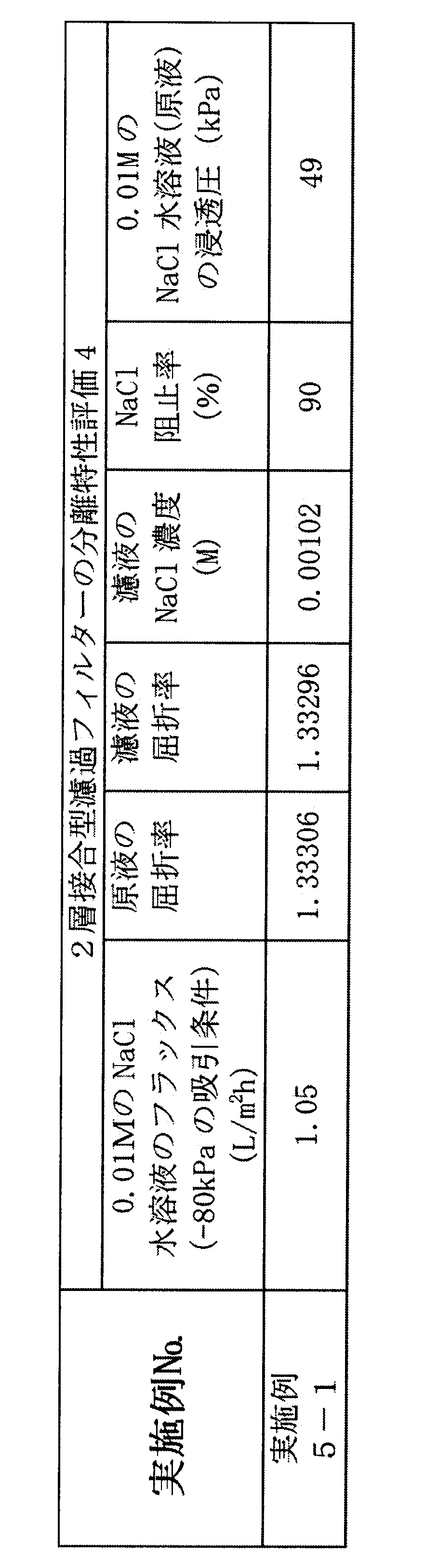
Claims (14)
- 硬質カーボン膜からなり、厚みが5nm以上300nm以下であり、孔の最大径が0.86nm未満であることを特徴とする硬質カーボン膜製NF又はRO膜。
- 硬質カーボン膜からなり、厚みが5nm以上300nm以下であり、有機溶媒中のアゾベンゼン色素を99%以上通過させないことを特徴とする硬質カーボン膜製NF又はRO膜。
- 有機溶媒耐性であることを特徴とする請求項1又は2に記載の硬質カーボン膜製NF又はRO膜。
- 硬質カーボン膜からなり、厚みが5nm以上300nm以下であり、水中のNaClを80%以上通過させないことを特徴とする硬質カーボン膜製NF又はRO膜。
- 前記硬質カーボン膜がダイヤモンド状カーボン膜であることを特徴とする請求項1、2又は4に記載の硬質カーボン膜製NF又はRO膜。
- 請求項1から5のうちのいずれか一項に記載の硬質カーボン膜製NF又はRO膜が多孔性支持基板の一面上に配置されていることを特徴とする濾過フィルター。
- 請求項1から5のうちのいずれか一項に記載の硬質カーボン膜製NF又はRO膜が限外濾過膜の一面に接合されている2層接合型濾過フィルターであって、前記限外濾過膜が表面に1μm2の範囲で50nm以上の局所的な凸部を含まず、表面の孔径が1nm以上50nm以下とされていることを特徴とする2層接合型濾過フィルター。
- 前記限外濾過膜が多孔性有機膜であることを特徴とする請求項7に記載の2層接合型濾過フィルター。
- 前記多孔性有機膜がポリスルホン(PSF)膜であることを特徴とする請求項8に記載の2層接合型濾過フィルター。
- 支持基板の一面に、スピンコーティング法、キャスト法、ディッピング法、又はダイコート法により中間層を形成する工程と、
前記中間層を形成した支持基板を真空チャンバー内に配置し、前記真空チャンバー内を減圧状態とし、前記支持基板を-20℃以上30℃以下の温度としてから、プラズマCVD法又はスパッタ法により、50nm/min以下の成膜速度で、前記中間層の一面に硬質カーボン膜を成膜する工程と、
前記硬質カーボン膜を成膜した支持基板を、水又は酸水溶液に浸漬して、前記支持基板から硬質カーボン膜製NF又はRO膜を剥離する工程と、
を含むことを特徴とする硬質カーボン膜製NF又はRO膜の製造方法。 - 前記中間層が、グルコース、スクロース、グルコース/スクロース混合物、グリセリン、ポリエチレングリコール、シリコン熱酸化膜の群から選択されるいずれか一の材料からなる膜であることを特徴とする請求項10に記載の硬質カーボン膜製NF又はRO膜の製造方法。
- 前記支持基板がシリコン又はガラスであることを特徴とする請求項10に記載の硬質カーボン膜製NF又はRO膜の製造方法。
- 請求項10から12のうちのいずれか一項に記載の硬質カーボン膜製NF又はRO膜の製造方法で製造した硬質カーボン膜製NF又はRO膜を、多孔性有機膜、多孔性無機膜又は多孔性金属膜のいずれか一の多孔性膜からなる多孔性支持基板の一面上に配置して、濾過フィルターを製造することを特徴とする濾過フィルターの製造方法。
- 表面に1μm2の範囲で50nm以上の局所的な凸部を含まず、表面の孔径が1nm以上50nm以下の限外濾過膜を調製後、有機溶媒洗浄処理と真空乾燥処理からなる前処理工程と、
前記前処理した限外濾過膜を、真空チャンバー内に配置し、前記真空チャンバー内を減圧状態とし、前記前処理した限外濾過膜を-20℃以上30℃以下の温度としてから、50nm/min以下の成膜速度で、プラズマCVD法又はスパッタ法により、前記前処理した限外濾過膜の一面に硬質カーボン膜製NF又はRO膜を成膜する工程と、
を含むことを特徴とする2層接合型濾過フィルターの製造方法。
Priority Applications (4)
| Application Number | Priority Date | Filing Date | Title |
|---|---|---|---|
| EP14866340.4A EP3085434B1 (en) | 2013-11-29 | 2014-11-28 | Nanofiltration or reverse osmosis membrane made of hard carbon film, filtering filter, two-layer-bonded-type filtering filter, and methods for manufacturing same |
| JP2015551019A JP6202450B2 (ja) | 2013-11-29 | 2014-11-28 | 硬質カーボン膜製nf又はro膜、濾過フィルター、2層接合型濾過フィルター及びそれらの製造方法 |
| US15/039,916 US20170001153A1 (en) | 2013-11-29 | 2014-11-28 | Nanofiltration or reverse osmosis membrane made of hard carbon film, filtering filter, two-layer-bonded-type filtering filter, and methods for manufacturing same |
| US16/848,319 US20200238223A1 (en) | 2013-11-29 | 2020-04-14 | Nanofiltration or reverse osmosis membrane made of hard carbon film, filtering filter, two-layer-bonded-type filtering filter, and methods for manufacturing same |
Applications Claiming Priority (6)
| Application Number | Priority Date | Filing Date | Title |
|---|---|---|---|
| JP2013-248276 | 2013-11-29 | ||
| JP2013248276 | 2013-11-29 | ||
| JP2014-081284 | 2014-04-10 | ||
| JP2014081284 | 2014-04-10 | ||
| JP2014166289 | 2014-08-19 | ||
| JP2014-166289 | 2014-08-19 |
Related Child Applications (2)
| Application Number | Title | Priority Date | Filing Date |
|---|---|---|---|
| US15/039,916 A-371-Of-International US20170001153A1 (en) | 2013-11-29 | 2014-11-28 | Nanofiltration or reverse osmosis membrane made of hard carbon film, filtering filter, two-layer-bonded-type filtering filter, and methods for manufacturing same |
| US16/848,319 Division US20200238223A1 (en) | 2013-11-29 | 2020-04-14 | Nanofiltration or reverse osmosis membrane made of hard carbon film, filtering filter, two-layer-bonded-type filtering filter, and methods for manufacturing same |
Publications (1)
| Publication Number | Publication Date |
|---|---|
| WO2015080259A1 true WO2015080259A1 (ja) | 2015-06-04 |
Family
ID=53199194
Family Applications (1)
| Application Number | Title | Priority Date | Filing Date |
|---|---|---|---|
| PCT/JP2014/081601 WO2015080259A1 (ja) | 2013-11-29 | 2014-11-28 | 硬質カーボン膜製nf又はro膜、濾過フィルター、2層接合型濾過フィルター及びそれらの製造方法 |
Country Status (4)
| Country | Link |
|---|---|
| US (2) | US20170001153A1 (ja) |
| EP (1) | EP3085434B1 (ja) |
| JP (1) | JP6202450B2 (ja) |
| WO (1) | WO2015080259A1 (ja) |
Cited By (3)
| Publication number | Priority date | Publication date | Assignee | Title |
|---|---|---|---|---|
| WO2017018482A1 (ja) * | 2015-07-28 | 2017-02-02 | 北川工業株式会社 | 逆浸透膜の製造方法 |
| JP2017064692A (ja) * | 2015-07-28 | 2017-04-06 | 北川工業株式会社 | 逆浸透膜の製造方法 |
| WO2019146671A1 (ja) | 2018-01-24 | 2019-08-01 | 北川工業株式会社 | 逆浸透膜、及び逆浸透膜の製造方法 |
Families Citing this family (5)
| Publication number | Priority date | Publication date | Assignee | Title |
|---|---|---|---|---|
| WO2017018378A1 (ja) * | 2015-07-28 | 2017-02-02 | 国立大学法人 鹿児島大学 | 水素ガス製造装置及び水素ガス製造方法 |
| US10427106B2 (en) * | 2016-05-02 | 2019-10-01 | Georgia Southern University Research and Service Foundation | Asymmetric membranes |
| KR102002367B1 (ko) * | 2016-10-20 | 2019-07-23 | 주식회사 엘지화학 | 역삼투막 보호층 형성용 조성물, 이를 이용한 역삼투막 제조방법, 역삼투막 및 수처리 모듈 |
| WO2019131792A1 (ja) * | 2017-12-28 | 2019-07-04 | 国立大学法人北海道大学 | 水素分離用膜 |
| CN108314001B (zh) * | 2018-03-02 | 2021-06-15 | 河南工程学院 | 高中孔率炭的制备方法 |
Citations (5)
| Publication number | Priority date | Publication date | Assignee | Title |
|---|---|---|---|---|
| JPS63185428A (ja) * | 1987-01-28 | 1988-08-01 | Sumitomo Electric Ind Ltd | ガス選択透過性複合膜 |
| WO2005087355A1 (ja) * | 2004-03-12 | 2005-09-22 | Ngk Insulators, Ltd. | 炭素膜積層体及びその製造方法、並びにvoc除去装置 |
| WO2011016478A1 (ja) | 2009-08-04 | 2011-02-10 | 独立行政法人物質・材料研究機構 | 濾過フィルターの製造方法及び濾過フィルター |
| JP2012036061A (ja) | 2010-08-11 | 2012-02-23 | National Institute For Materials Science | ナノカーボン膜の製造方法及びナノカーボン膜 |
| JP2013193053A (ja) * | 2012-03-22 | 2013-09-30 | Ngk Insulators Ltd | 浸透気化膜の製造方法および浸透気化法 |
Family Cites Families (9)
| Publication number | Priority date | Publication date | Assignee | Title |
|---|---|---|---|---|
| DE3013357A1 (de) * | 1980-04-05 | 1981-10-08 | Fraunhofer-Gesellschaft zur Förderung der angewandten Forschung e.V., 8000 München | Verfahren zum herstellen einer biovertraeglichen poren-membran definierter trennschaerfe (ausschlussgrenze) |
| US6039792A (en) * | 1997-06-24 | 2000-03-21 | Regents Of The University Of California And Bp Amoco Corporation | Methods of forming and using porous structures for energy efficient separation of light gases by capillary condensation |
| JP2002177747A (ja) * | 2000-12-11 | 2002-06-25 | Hitachi Maxell Ltd | 選択透過膜及びこれを用いた空気電池 |
| JP3855044B2 (ja) * | 2001-11-21 | 2006-12-06 | 独立行政法人産業技術総合研究所 | 分子篩炭素膜による水素の精製方法 |
| US7051883B2 (en) * | 2003-07-07 | 2006-05-30 | Reemay, Inc. | Wetlaid-spunbond laminate membrane support |
| JP4743473B2 (ja) * | 2004-08-06 | 2011-08-10 | 住友電気工業株式会社 | 導電性ダイヤモンド被覆基板 |
| US7901776B2 (en) * | 2006-12-29 | 2011-03-08 | 3M Innovative Properties Company | Plasma deposited microporous carbon material |
| JP5462105B2 (ja) * | 2010-08-05 | 2014-04-02 | 株式会社フジクラ | ファラデー回転子用ガーネット型単結晶及びそれを用いた光アイソレータ |
| US8709536B2 (en) * | 2010-09-01 | 2014-04-29 | International Business Machines Corporation | Composite filtration membranes and methods of preparation thereof |
-
2014
- 2014-11-28 US US15/039,916 patent/US20170001153A1/en not_active Abandoned
- 2014-11-28 WO PCT/JP2014/081601 patent/WO2015080259A1/ja active Application Filing
- 2014-11-28 JP JP2015551019A patent/JP6202450B2/ja active Active
- 2014-11-28 EP EP14866340.4A patent/EP3085434B1/en active Active
-
2020
- 2020-04-14 US US16/848,319 patent/US20200238223A1/en not_active Abandoned
Patent Citations (5)
| Publication number | Priority date | Publication date | Assignee | Title |
|---|---|---|---|---|
| JPS63185428A (ja) * | 1987-01-28 | 1988-08-01 | Sumitomo Electric Ind Ltd | ガス選択透過性複合膜 |
| WO2005087355A1 (ja) * | 2004-03-12 | 2005-09-22 | Ngk Insulators, Ltd. | 炭素膜積層体及びその製造方法、並びにvoc除去装置 |
| WO2011016478A1 (ja) | 2009-08-04 | 2011-02-10 | 独立行政法人物質・材料研究機構 | 濾過フィルターの製造方法及び濾過フィルター |
| JP2012036061A (ja) | 2010-08-11 | 2012-02-23 | National Institute For Materials Science | ナノカーボン膜の製造方法及びナノカーボン膜 |
| JP2013193053A (ja) * | 2012-03-22 | 2013-09-30 | Ngk Insulators Ltd | 浸透気化膜の製造方法および浸透気化法 |
Non-Patent Citations (5)
| Title |
|---|
| J. D. FERRY, J. GEN. PHYSIOL., vol. 20, 1936, pages 95 - 104 |
| J. R. HOLLAHAN; T. WYDEVEN, SCIENCE, vol. 179, 1973, pages 500 - 501 |
| S. KARAN; S. SAMITSU; X. PENG; K. KURASHIMA; I. ICHINOSE, SCIENCE, vol. 335, 2012, pages 444 - 447 |
| See also references of EP3085434A4 |
| YOSHIHISA FUJII; SADAKI SAMITSU; IZUMI ICHINOSE: "Future Prospects of Porous Diamond-like Carbon Films", MEMBRANE, vol. 38, no. 5, 2013, pages 200 - 206 |
Cited By (9)
| Publication number | Priority date | Publication date | Assignee | Title |
|---|---|---|---|---|
| WO2017018482A1 (ja) * | 2015-07-28 | 2017-02-02 | 北川工業株式会社 | 逆浸透膜の製造方法 |
| JP2017064692A (ja) * | 2015-07-28 | 2017-04-06 | 北川工業株式会社 | 逆浸透膜の製造方法 |
| KR20180023964A (ko) * | 2015-07-28 | 2018-03-07 | 키타가와고우교가부시끼가이샤 | 역침투막의 제조 방법 |
| CN107847877A (zh) * | 2015-07-28 | 2018-03-27 | 北川工业株式会社 | 反渗透膜的制造方法 |
| KR101981644B1 (ko) | 2015-07-28 | 2019-05-23 | 키타가와고우교가부시끼가이샤 | 역침투막의 제조 방법 |
| US10751668B2 (en) | 2015-07-28 | 2020-08-25 | Kitagawa Industries Co., Ltd. | Method of forming reverse osmosis membrane |
| WO2019146671A1 (ja) | 2018-01-24 | 2019-08-01 | 北川工業株式会社 | 逆浸透膜、及び逆浸透膜の製造方法 |
| KR20200072551A (ko) | 2018-01-24 | 2020-06-22 | 키타가와고우교가부시끼가이샤 | 역침투막 및 역침투막의 제조 방법 |
| US11452973B2 (en) | 2018-01-24 | 2022-09-27 | Kitagawa Industries Co., Ltd. | Reverse osmosis membrane and method for producing reverse osmosis membrane |
Also Published As
| Publication number | Publication date |
|---|---|
| EP3085434A4 (en) | 2017-10-11 |
| JPWO2015080259A1 (ja) | 2017-03-16 |
| EP3085434B1 (en) | 2019-09-18 |
| EP3085434A1 (en) | 2016-10-26 |
| JP6202450B2 (ja) | 2017-09-27 |
| US20170001153A1 (en) | 2017-01-05 |
| US20200238223A1 (en) | 2020-07-30 |
Similar Documents
| Publication | Publication Date | Title |
|---|---|---|
| JP6202450B2 (ja) | 硬質カーボン膜製nf又はro膜、濾過フィルター、2層接合型濾過フィルター及びそれらの製造方法 | |
| Zhang et al. | Nanofiltration membranes with hydrophobic microfiltration substrates for robust structure stability and high water permeation flux | |
| Liu et al. | High-performance polyamide/ceramic hollow fiber TFC membranes with TiO2 interlayer for pervaporation dehydration of isopropanol solution | |
| CN109331659B (zh) | 一种自组装层间距可调rGO复合膜的制备方法 | |
| Hou et al. | Carbon nanotube networks as nanoscaffolds for fabricating ultrathin carbon molecular sieve membranes | |
| Ibrahim et al. | Robust organosilica membranes for high temperature reverse osmosis (RO) application: Membrane preparation, separation characteristics of solutes and membrane regeneration | |
| EP3852906A1 (en) | Membranes for forward osmosis and membrane distillation and process of treating fracking wastewater | |
| Li et al. | Pinning down the water transport mechanism in graphene oxide pervaporation desalination membranes | |
| US10099183B2 (en) | Solvent-resistant separation membrane | |
| Li et al. | Exploring the dependence of bulk properties on surface chemistries and microstructures of commercially composite RO membranes by novel characterization approaches | |
| CS257751B2 (en) | Multicomponent membrane for gas separation | |
| Fang et al. | Effect of the supporting layer structures on antifouling properties of forward osmosis membranes in AL-DS mode | |
| JP2019058908A (ja) | 1234yfおよび1234zeをベースとするポリマー膜材料、膜の調製およびその使用 | |
| KR101440970B1 (ko) | 역삼투 분리막의 제조 방법 및 이에 의해 제조된 역삼투 분리막 | |
| JP2004123533A (ja) | 含浸−ローリング法による熱的安定性に優れたシリカ複合膜の製造方法 | |
| Wang et al. | Fabrication, characterization and separation properties of three-channel stainless steel hollow fiber membrane | |
| Yang et al. | Gradient nanoporous phenolics as substrates for high-flux nanofiltration membranes by layer-by-layer assembly of polyelectrolytes | |
| JP5527662B2 (ja) | ナノカーボン膜の製造方法及びナノカーボン膜 | |
| KR20170090904A (ko) | 혈액 투석용 막 및 그 제조방법 | |
| JP2009183814A (ja) | 分離膜及びその製造方法 | |
| JP7447282B2 (ja) | 有機溶媒ナノろ過のためのナノ選択性表面を有する高透過性複合膜 | |
| Choi et al. | Ultrathin organosiloxane membrane for precision organic solvent nanofiltration | |
| KR101244695B1 (ko) | 초임계 유체를 이용한 금속 나노 입자가 코팅된 분리막의 제조방법 | |
| AHMADIAN et al. | An optimum routine for surface modification of ceramic supports to facilitate deposition of defect-free overlaying micro and meso (nano) porous membrane | |
| JPWO2017014130A1 (ja) | 多孔質膜、水処理膜及び多孔質膜の製造方法 |
Legal Events
| Date | Code | Title | Description |
|---|---|---|---|
| 121 | Ep: the epo has been informed by wipo that ep was designated in this application |
Ref document number: 14866340 Country of ref document: EP Kind code of ref document: A1 |
|
| ENP | Entry into the national phase |
Ref document number: 2015551019 Country of ref document: JP Kind code of ref document: A |
|
| WWE | Wipo information: entry into national phase |
Ref document number: 15039916 Country of ref document: US |
|
| NENP | Non-entry into the national phase |
Ref country code: DE |
|
| REEP | Request for entry into the european phase |
Ref document number: 2014866340 Country of ref document: EP |
|
| WWE | Wipo information: entry into national phase |
Ref document number: 2014866340 Country of ref document: EP |