WO2015079901A1 - ロックアップ装置およびトルクコンバータ - Google Patents
ロックアップ装置およびトルクコンバータ Download PDFInfo
- Publication number
- WO2015079901A1 WO2015079901A1 PCT/JP2014/079813 JP2014079813W WO2015079901A1 WO 2015079901 A1 WO2015079901 A1 WO 2015079901A1 JP 2014079813 W JP2014079813 W JP 2014079813W WO 2015079901 A1 WO2015079901 A1 WO 2015079901A1
- Authority
- WO
- WIPO (PCT)
- Prior art keywords
- damper
- clutch piston
- damper spring
- torque converter
- lockup device
- Prior art date
- Legal status (The legal status is an assumption and is not a legal conclusion. Google has not performed a legal analysis and makes no representation as to the accuracy of the status listed.)
- Ceased
Links
Images

Classifications
-
- F—MECHANICAL ENGINEERING; LIGHTING; HEATING; WEAPONS; BLASTING
- F16—ENGINEERING ELEMENTS AND UNITS; GENERAL MEASURES FOR PRODUCING AND MAINTAINING EFFECTIVE FUNCTIONING OF MACHINES OR INSTALLATIONS; THERMAL INSULATION IN GENERAL
- F16H—GEARING
- F16H45/00—Combinations of fluid gearings for conveying rotary motion with couplings or clutches
- F16H45/02—Combinations of fluid gearings for conveying rotary motion with couplings or clutches with mechanical clutches for bridging a fluid gearing of the hydrokinetic type
-
- F—MECHANICAL ENGINEERING; LIGHTING; HEATING; WEAPONS; BLASTING
- F16—ENGINEERING ELEMENTS AND UNITS; GENERAL MEASURES FOR PRODUCING AND MAINTAINING EFFECTIVE FUNCTIONING OF MACHINES OR INSTALLATIONS; THERMAL INSULATION IN GENERAL
- F16D—COUPLINGS FOR TRANSMITTING ROTATION; CLUTCHES; BRAKES
- F16D25/00—Fluid-actuated clutches
- F16D25/06—Fluid-actuated clutches in which the fluid actuates a piston incorporated in, i.e. rotating with the clutch
- F16D25/062—Fluid-actuated clutches in which the fluid actuates a piston incorporated in, i.e. rotating with the clutch the clutch having friction surfaces
- F16D25/063—Fluid-actuated clutches in which the fluid actuates a piston incorporated in, i.e. rotating with the clutch the clutch having friction surfaces with clutch members exclusively moving axially
- F16D25/0635—Fluid-actuated clutches in which the fluid actuates a piston incorporated in, i.e. rotating with the clutch the clutch having friction surfaces with clutch members exclusively moving axially with flat friction surfaces, e.g. discs
-
- F—MECHANICAL ENGINEERING; LIGHTING; HEATING; WEAPONS; BLASTING
- F16—ENGINEERING ELEMENTS AND UNITS; GENERAL MEASURES FOR PRODUCING AND MAINTAINING EFFECTIVE FUNCTIONING OF MACHINES OR INSTALLATIONS; THERMAL INSULATION IN GENERAL
- F16F—SPRINGS; SHOCK-ABSORBERS; MEANS FOR DAMPING VIBRATION
- F16F15/00—Suppression of vibrations in systems; Means or arrangements for avoiding or reducing out-of-balance forces, e.g. due to motion
- F16F15/10—Suppression of vibrations in rotating systems by making use of members moving with the system
- F16F15/12—Suppression of vibrations in rotating systems by making use of members moving with the system using elastic members or friction-damping members, e.g. between a rotating shaft and a gyratory mass mounted thereon
- F16F15/121—Suppression of vibrations in rotating systems by making use of members moving with the system using elastic members or friction-damping members, e.g. between a rotating shaft and a gyratory mass mounted thereon using springs as elastic members, e.g. metallic springs
- F16F15/123—Wound springs
-
- F—MECHANICAL ENGINEERING; LIGHTING; HEATING; WEAPONS; BLASTING
- F16—ENGINEERING ELEMENTS AND UNITS; GENERAL MEASURES FOR PRODUCING AND MAINTAINING EFFECTIVE FUNCTIONING OF MACHINES OR INSTALLATIONS; THERMAL INSULATION IN GENERAL
- F16H—GEARING
- F16H45/00—Combinations of fluid gearings for conveying rotary motion with couplings or clutches
- F16H45/02—Combinations of fluid gearings for conveying rotary motion with couplings or clutches with mechanical clutches for bridging a fluid gearing of the hydrokinetic type
- F16H2045/0205—Combinations of fluid gearings for conveying rotary motion with couplings or clutches with mechanical clutches for bridging a fluid gearing of the hydrokinetic type two chamber system, i.e. without a separated, closed chamber specially adapted for actuating a lock-up clutch
-
- F—MECHANICAL ENGINEERING; LIGHTING; HEATING; WEAPONS; BLASTING
- F16—ENGINEERING ELEMENTS AND UNITS; GENERAL MEASURES FOR PRODUCING AND MAINTAINING EFFECTIVE FUNCTIONING OF MACHINES OR INSTALLATIONS; THERMAL INSULATION IN GENERAL
- F16H—GEARING
- F16H45/00—Combinations of fluid gearings for conveying rotary motion with couplings or clutches
- F16H45/02—Combinations of fluid gearings for conveying rotary motion with couplings or clutches with mechanical clutches for bridging a fluid gearing of the hydrokinetic type
- F16H2045/0221—Combinations of fluid gearings for conveying rotary motion with couplings or clutches with mechanical clutches for bridging a fluid gearing of the hydrokinetic type with damping means
-
- F—MECHANICAL ENGINEERING; LIGHTING; HEATING; WEAPONS; BLASTING
- F16—ENGINEERING ELEMENTS AND UNITS; GENERAL MEASURES FOR PRODUCING AND MAINTAINING EFFECTIVE FUNCTIONING OF MACHINES OR INSTALLATIONS; THERMAL INSULATION IN GENERAL
- F16H—GEARING
- F16H45/00—Combinations of fluid gearings for conveying rotary motion with couplings or clutches
- F16H45/02—Combinations of fluid gearings for conveying rotary motion with couplings or clutches with mechanical clutches for bridging a fluid gearing of the hydrokinetic type
- F16H2045/0273—Combinations of fluid gearings for conveying rotary motion with couplings or clutches with mechanical clutches for bridging a fluid gearing of the hydrokinetic type characterised by the type of the friction surface of the lock-up clutch
- F16H2045/0278—Combinations of fluid gearings for conveying rotary motion with couplings or clutches with mechanical clutches for bridging a fluid gearing of the hydrokinetic type characterised by the type of the friction surface of the lock-up clutch comprising only two co-acting friction surfaces
Definitions
- the present invention relates to a lock-up device in a torque converter that amplifies a driving force from an engine using hydraulic oil and transmits it to an output shaft side, and a torque converter including the lock-up device.
- a torque converter is provided between the engine and the transmission.
- a torque converter is a mechanical device that amplifies and transmits a driving force from an engine to an output shaft side by circulating hydraulic oil between a pump impeller and a turbine runner that are arranged to face each other.
- a lockup device is provided for the purpose of improving the fuel efficiency of the vehicle.
- the lock-up device is configured such that the clutch piston connected to the turbine runner contacts or separates from the torque converter cover that rotates integrally with the pump impeller, and the clutch piston contacts the torque converter cover.
- the pump impeller and the turbine runner are directly connected to transmit the driving force on the pump impeller side directly to the turbine runner side.
- a coil-shaped damper spring is provided between the clutch piston and the turbine runner in order to attenuate the driving force fluctuation (also referred to as “torque fluctuation”) from the engine.
- damper springs arranged in series with each other are connected via an intermediate support portion in an intermediate member formed in a ring shape, thereby causing a piston member (corresponding to a clutch piston) to radially outward.
- a lockup damper mechanism (corresponding to a lockup device) that restricts the movement of a damper spring is disclosed.
- the present invention has been made to address the above-described problems, and an object of the present invention is to provide a lockup device and torque that can suppress the hysteresis torque caused by the friction between the damper spring and the clutch piston and improve the torque fluctuation damping performance of the engine. To provide a converter.
- the present invention is characterized in that a disc-shaped clutch piston supported so as to be able to contact or be separated from a pump impeller that is rotationally driven by the driving force of an engine, and a circumferential direction of the clutch piston.
- a lockup device having a coiled damper spring and a connecting body for connecting a clutch piston via a damper spring to a turbine runner disposed opposite to a pump impeller via hydraulic oil, the damper spring is connected from both ends.
- the clutch piston includes not only a case where the clutch piston directly contacts the pump impeller, but also a case where the clutch piston indirectly contacts via a member (for example, a torque converter cover) that rotates integrally with the pump impeller.
- the lockup device since the damper pressing portion presses the central portion of the damper spring against the overhang portion of the intermediate member, Displacement and deformation outward in the radial direction are suppressed.
- the lockup device can suppress the generation of the His torque due to the friction between the damper spring and the clutch piston, and can improve the damping performance of the engine torque fluctuation.
- it is effective to use a damper spring with a low spring constant to effectively attenuate engine torque fluctuations, but the damper spring with a low spring constant is also deformed to the clutch piston side by buckling during contraction. easy.
- deformation to the clutch piston side can be effectively suppressed even in a damper spring having a low spring constant.
- At least one of the pair of damper pressing portions is formed such that a radially outer portion of the clutch piston projects toward a damper spring with respect to the radially inner portion.
- the lock-up device is configured such that at least one of the pair of damper pressing portions projects a radially outer portion of the clutch piston to a damper spring side with respect to the radially inner portion. Therefore, the damper spring can be pushed with high accuracy so as to protrude toward the inside in the radial direction of the clutch piston. It should be noted that at least one of the pair of damper pressing portions can be configured to contact only a portion on the radially outer side of the clutch piston with respect to the axis of the damper spring.
- the lock-up device is configured such that the intermediate member is positioned more than the radially inner side surface of the clutch piston at the center of the damper spring until the rotational speed of the clutch piston reaches at least 1500 rpm. This is because the overhanging portion is formed with an overhanging amount protruding outward in the same radial direction.
- the lock-up device includes a rotation speed of the clutch piston of at least 1500 rpm (even if it is less than 1500 rpm, it can be regarded as substantially 1500 rpm). ) Until the center part of the damper spring reaches the outer side in the radial direction, so that the protruding part of the intermediate member protrudes outward in the same radial direction. The damping performance can be improved.
- the intermediate member is formed in a wall shape in which the overhanging portion extends along the side surface of the damper spring.
- the lock-up device has a wall-like shape in which the protruding portion of the intermediate member extends along the side surface of the damper spring.
- the damper spring side can be received with high accuracy.
- the present invention can be implemented not only as an invention of a lockup device but also as an invention of a torque converter provided with this lockup device.
- the torque converter includes a pump impeller that is rotationally driven by the driving force of the engine, a turbine runner that is disposed so as to be rotationally driven at a position facing the pump impeller, and a pump impeller and the turbine runner.
- the torque converter provided with the hydraulic oil provided may be provided with the lockup device according to any one of claims 1 to 4. In the torque converter configured as described above, the same effect as that of the lockup device can be expected.
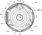
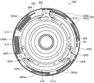
- FIG. 3 is a front view schematically showing a configuration of a lockup device in the torque converter shown in FIGS. 1 and 2, respectively.
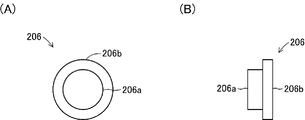
- FIGS. 1A and 1B show the external configuration of the receiving piece shown in FIGS. 1 to 3, respectively.
- FIG. 1A is a front view of the receiving piece
- FIG. 2B is a side view of the receiving piece.
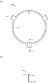
- (A) and (B) show the external configuration of the intermediate member shown in FIGS. 1 to 3, respectively.
- (A) is a front view of the intermediate member
- (B) shows C shown in (A).
- FIG. 10 is a cross-sectional view of the intermediate member as viewed from line -C.
- FIG. 4 is a front view schematically showing an operating state (twisted state of about 30 Nm) of the lockup device shown in FIG. 3.
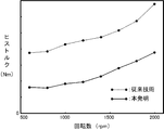
- FIG. 6 shows the results of a comparative experiment of His torque in a torque converter having a lock-up device according to the present invention and a torque converter according to the prior art, where the vertical axis is the His torque and the horizontal axis is the engine speed.
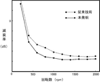
- the comparative experiment result of the damping performance in the torque converter provided with the lock-up device according to the present invention and the torque converter according to the prior art is shown, where the vertical axis is the damping factor and the horizontal axis is the engine speed. It is the side view which showed roughly the external appearance structure of the receiving piece which concerns on the modification of this invention.
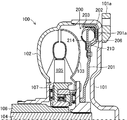
- FIG. 1 is a cross-sectional view schematically showing a configuration of a torque converter 100 including a lockup device 200 according to the present invention. 1 corresponds to a cross-sectional view of the torque converter 100 as seen from the line AA shown in FIG.
- FIG. 2 is a cross-sectional view schematically showing a configuration of the torque converter 100 including the lockup device 200 according to the present invention in a cross section different from that of FIG. 2 corresponds to a cross-sectional view of the torque converter 100 as seen from the line BB shown in FIG.
- FIG. 1 is a cross-sectional view schematically showing a configuration of a torque converter 100 including a lockup device 200 according to the present invention. 1 corresponds to a cross-sectional view of the torque converter 100 as seen from the line AA shown in FIG.
- FIG. 2 is a cross-sectional view schematically showing a configuration of the torque converter 100 including the lockup device 200 according to the present invention in a cross section different from that of FIG. 2 corresponds to a cross
- the torque converter 100 is a mechanical device that is provided between an engine and a transmission mainly in an automobile (so-called AT car) that includes an automatic transmission, and amplifies the driving force of the engine and transmits it to the transmission.
- AT car a transmission mainly in an automobile
- the torque converter 100 includes a torque converter cover 101.
- the torque converter cover 101 is a component that is rotationally driven by a driving force from a vehicle engine (not shown), and is formed in a substantially cup shape in which the edge of the disk is bent and extended.
- the torque converter cover 101 is connected to a crankshaft (not shown) whose rear surface (right side surface in the figure) extends from the engine via a connecting part 101a, and a pump impeller 102 is provided at a bent edge.
- the pump impeller 102 is an impeller that is rotated integrally with the torque converter cover 101 and sends hydraulic oil (not shown) to the turbine runner 103.
- the pump impeller 102 is fixedly attached to the torque converter cover 101 and is relatively rotated with respect to the stator 105. It is attached as possible.
- the turbine runner 103 is an impeller that is rotated by the flow of hydraulic oil by the rotational drive of the pump impeller 102, and is provided in a state of being opposed to the pump impeller 102 and relatively rotatable.
- the turbine runner 103 is spline-fitted to an output shaft 104 extending from a transmission (not shown) and is attached to the stator 105 so as to be relatively rotatable.
- the stator 105 is an impeller that rectifies the flow of hydraulic oil flowing back from the turbine runner 103 and sends it to the pump impeller 101.
- the stator 105 is provided with a one-way clutch 107 for the stator shaft 106 that is supported by the transmission in a non-rotatable state. Is attached through.
- the one-way clutch 107 is a component that supports the stator 105 so as to be rotatable only in the same direction as the rotation direction of the turbine runner 103, and is spline-fitted onto the stator shaft 106.
- a lockup device 200 is provided between the torque converter cover 101 and the turbine runner 103.
- the lockup device 200 is a mechanical device for directly connecting the pump impeller 102 and the turbine runner 103 without using hydraulic oil, and includes a clutch piston 201.
- the clutch piston 201 is a part for bringing the turbine runner 103 into a connected state or a non-connected state with respect to the torque converter cover 101 formed integrally with the pump impeller 102. It is formed in a substantially tray shape.
- the clutch piston 201 is slidably fitted on the cylindrical portion of the turbine runner 103 that is spline-fitted to the output shaft 104 so as to be displaced within a range in contact with or away from the inner surface of the torque converter cover 101. And is supported. Further, the outer edge portion of the clutch piston 201 is formed such that the plate surface on the torque converter cover 101 side protrudes toward the inner surface of the torque converter cover 101 and the plate surface on the turbine runner 103 side is recessed in a concave shape.
- a friction material 201a is provided at a portion protruding toward the inner surface of the torque converter cover 101, and a damper spring 203 is provided through a guide blade 202 at the concave portion. .
- the guide plate 202 is a metal part that is disposed between the damper spring 203 and the inner surface of the clutch piston 201 to prevent frictional contact therebetween and to improve the stretchability of the damper spring 203.
- the ring body corresponding to the circumferential direction of 201 is configured by three curved piece-like bodies obtained by equally dividing the ring body into three.
- the guide plate 202 has a substantially L-shaped cross section corresponding to a corner on the inner surface of the clutch piston 201.
- the damper spring 203 is a component that transmits to the turbine runner 103 while attenuating fluctuations in rotational driving force (torque) transmitted from the engine via the torque converter cover 101, and is configured by a steel coil spring.
- two damper springs 203 a and 203 b are arranged via an intermediate member 210 between three damper holders 204 provided on the surface of the turbine runner 103 side.
- the damper holder 204 is a part for receiving both end portions of the damper spring 203 constituted by a pair of damper springs 203a and 203b and for projecting the central portion of the damper spring 203 to the inside of the clutch piston 201 in the radial direction. 201 extends from the inside in the radial direction toward the outside. More specifically, the damper holder 204 is attached to the inner side in the radial direction than the part where the damper spring 203 is disposed in the clutch piston 201, and the damper pressing part 205 extends from the attachment part toward the outer side in the radial direction. ing.
- the damper pressing portion 205 is a portion in which both end portions of the damper spring 203 are in contact with each other via the receiving piece 206, and the radially outer portion of the clutch piston 201 in the damper pressing portion 205 is in relation to the radially inner portion. It is formed to project to the damper spring 203 side. In other words, the damper pressing portion 205 is formed so that the circumferential width of the clutch piston 201 increases toward the radially outer side of the clutch piston 201. Further, the damper pressing portion 205 is formed to be recessed toward the clutch piston 201 so that a connecting body, which will be described later, can be displaced along the circumferential direction of the clutch piston 201.
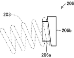
- the receiving piece 206 is a component that is fitted into each end of each of the damper springs 203 a and 203 b that constitute the damper spring 203, and a fitting portion 206 a that fits into the hole of the damper spring 203. It is composed of two cylindrical portions with an end face contact portion 206b addressed to the end portion of the damper spring 203.
- the intermediate member 210 is a metal part that regulates the movement and deformation of the damper spring 203a and the damper spring 203b.
- a portion 212 and an overhang portion 213 are provided.
- the main body ring portion 211 is a portion that is slidably attached radially inward from the portion of the clutch piston 201 where the damper spring 203 is disposed, and is formed in a ring shape.
- a damper pressing portion 212 is formed so as to project radially outward at a position that divides the main body ring portion 211 into three equal parts, and between these three damper pressing portions 212.
- the outer peripheral portion of each is bent toward the inner surface side of the clutch piston 201 to form an overhang portion 213.
- the damper pressing portion 212 is a portion where the mutually facing ends of the damper spring 203a and the damper spring 203b are in contact with each other via the receiving piece 206, and the outer side in the radial direction of the clutch piston 201 This portion is formed to protrude toward the damper spring 203 with respect to the inner portion in the same radial direction.
- the damper pressing portion 212 is formed so that the circumferential width of the clutch piston 201 increases toward the radially outer side of the clutch piston 201.
- the damper pressing portion 212 is disposed between the damper spring 203a and the damper spring 203b and connects the damper springs 203a and the damper springs 203b in series.
- the damper spring 203a and the damper spring 203b sandwiched between the damper pressing portion 205 and the damper pressing portion 212 are deformed so that each central portion protrudes radially inward of the clutch piston 201 with respect to both ends.
- the damper pressing portion 205 and the damper pressing portion 212 correspond to a pair of damper pressing portions according to the present invention.
- the overhanging portion 213 receives the central portions of the damper springs 203a and 203b that have received the force projecting inward in the radial direction of the clutch piston 201 by the damper pressing portion 205 and the damper pressing portion 212, and is displaced inward in the same radial direction. It is a portion that restricts deformation, and is bent and extended from the main body ring portion 211 with a protruding amount for receiving the side portions of the damper springs 203a and 203b.
- the overhanging amount of the overhanging portion 213 is such that at least the damper springs 203a and 203b are deformed and arranged in an arc shape along the circumferential direction of the clutch piston 201. It is set to an amount projecting radially outward from the inner peripheral side surface of 203b. In the present embodiment, the overhanging portion 213 is set to an overhanging amount that can contact the side surface portions of the respective center portions of the damper springs 203a and 203b even when the clutch piston 201 is rotationally driven at a speed of 1500 rpm. Yes.
- the outer diameter of the main body ring portion 211 in this embodiment is a circular shape having a diameter that can contact the side surface portions of the respective center portions of the damper springs 203a and 203b even when the clutch piston 201 is rotationally driven at a speed of 1500 rpm. Is formed.
- the intermediate member 210 is attached in a state in which the main body ring portion 211 is slidable in the circumferential direction on the clutch piston 201 so that the damper pressing portion 212 is positioned in the middle of the three damper holders 204 in the circumferential direction.
- the damper springs 203a and 203b are pressed at both ends by the damper pressing portion 205 and the damper pressing portion 212, and the central portion is displaced and / or deformed radially inward of the clutch piston 201 to form the overhanging portion 213.
- the clutch piston 201 is accommodated in a pressed state.
- a cover 214 for covering the intermediate member 210 and a part of the damper spring 203 on the intermediate member 210 between the three damper holders 204 and holding the intermediate member 210 in a slidable state is provided. It is attached.
- one of the three covers 214 is indicated by a two-dot chain line in order to clarify the configuration inside the cover 214.
- the connecting body 220 is a metal part for connecting the turbine runner 103 to the clutch piston 201, and is formed in a plate shape extending from the outer peripheral portion of the turbine runner 103.
- the distal end portion of the coupling body 220 extends into the damper pressing portion 212 of the damper holder 204 and is in contact with one end portion of the damper spring 203a.
- the distal end portion of the coupling body 220 is formed so as to contact a portion on the radially outer side of the clutch piston 201 with respect to the axis line of the damper spring 203a via the receiving piece 206.
- the connecting body 220 can be deformed so that the center portion projects outwardly in the radial direction of the clutch piston 201 with respect to both ends, similarly to the damper pressing portions 205 and 212. it can. That is, in this embodiment, the front-end
- This torque converter 100 functions by being disposed between an engine and a transmission in a so-called AT vehicle. Specifically, in the torque converter 100, first, the rotational drive force of the engine is transmitted to the torque converter cover 101 by the release of the brake and the depression of the accelerator pedal by the driver of the vehicle, and the torque converter cover 101 and the pump impeller 102 are integrated. Rotating drive. Next, in the torque converter 100, the turbine runner 103 is rotationally driven as the hydraulic oil in the torque converter 100 circulates. As a result, the vehicle starts traveling.
- the lock-up device 200 Attenuates the torque fluctuation by the expansion and contraction of the damper spring 203 according to the torque fluctuation from the engine. More specifically, the damper spring 203a of the pair of damper springs 203a and 203b constituting the damper spring 203 is sandwiched between the distal end portion of the coupling body 220 and the damper pressing portion 212 to be compressed and deformed, and the damper spring 203b. Is compressed between the damper pressing portion 212 and the damper pressing portion 205.
- the damper spring 203a is displaced radially outwardly of the clutch piston 201 because the central portion of the damper spring 203a and the damper pressing portion 212 project toward the overhang portion 213 and are pressed against the overhang portion 213. Or deformation is regulated. Further, the damper spring 203b has a central portion that protrudes toward the overhanging portion 213 and is pressed against the overhanging portion 213 by the damper pressing portion 212 and the damper pressing portion 205, so that the clutch piston 201 is displaced or deformed outward in the radial direction. Be regulated.
- the lock-up device 200 prevents the damper springs 203a and 203b from coming into contact with the inner peripheral surface of the clutch piston 201 due to the rotational drive of the clutch piston 201, thereby increasing the hysteresis torque.
- the experimental results by the present inventor will be described.
- the inventor conducted a comparative experiment of the hysteresis torque and the damping performance of the damper spring 203 in the lockup device 200 in the present embodiment and the conventional lockup device.
- the conventional lockup device is configured by arranging a damper spring 203 curved in an arc shape along the circumferential direction inside the clutch piston 201.
- both end portions of the damper spring 203 are sandwiched between damper pressing portions parallel to the both end portions, and the center portion of the damper spring 203 is not supported by the intermediate member 210.
- the connecting body extending from the turbine runner 103 has a tip portion facing the axis of the damper spring 203.
- FIG. 7 is a comparative graph of the hysteresis torque between the lockup device 200 in the present embodiment and the conventional lockup device, where the vertical axis is the amount of historque and the horizontal axis is the rotational speed of the clutch piston 201.
- FIG. 8 is a comparison graph of the damping performance between the lockup device 200 of the present embodiment and the conventional lockup device, where the vertical axis is the damping rate of the variable torque, and the horizontal axis is the rotational speed of the clutch piston 201. is there.
- the lockup device 200 in the present embodiment can obviously reduce the hysteresis torque and can attenuate the torque fluctuation as compared with the conventional lockup device.
- the lock-up device 200 includes the damper pressing portions 205 and 212 and the connecting body 220 at the center portion of the damper spring 203 as the overhang portion 213 of the intermediate member 210. Due to the pressing, the displacement and deformation of the damper spring 203 to the outside in the radial direction when the clutch piston 201 is driven to rotate are suppressed. Thereby, the lockup device 200 can suppress the generation of the His torque due to the friction between the damper spring 203 and the clutch piston 201, and can improve the damping performance of the engine torque fluctuation. In particular, it is effective to use a low spring constant damper spring 203 to effectively attenuate engine torque fluctuations.
- the low spring constant damper spring 203 is moved toward the clutch piston 201 by buckling during contraction. Are also easily deformed. However, according to the lockup device 200 according to the present invention, the deformation toward the clutch piston 201 can be effectively suppressed even in the damper spring 203 having a low spring constant.
- the lock-up device 200 is configured so that the radially outer portion of the clutch piston 201 has the same radial direction at each contact portion of the damper pressing portions 205 and 212 that sandwich the damper spring 203 from both ends. It was formed so as to protrude toward the damper spring 201 side (in other words, in the circumferential direction) with respect to the inner portion.
- the damper pressing portions 205 and 212 need only be able to apply a force that causes the central portion of the damper spring 203 to project outward in the radial direction of the clutch piston 201. Therefore, the damper pressing portions 205 and 212 are disposed at both ends of the damper springs 203a and 203b. What is necessary is just to form so that the radial direction outer side part in the clutch piston 201 may protrude over the damper spring 201 side with respect to the same radial direction inner part about at least one of the damper pressing parts 205 and 212.
- the coupling body 220 is disposed so as to press the portion on the radially outer side of the clutch piston 201 with respect to the damper spring 203a with respect to the axial line, so that the central portion of the damper spring 203 is connected to the clutch piston 201. It is comprised so that it may protrude toward the radial inside. Therefore, the damper pressing portion according to the present invention can be configured by only the connecting body 220 in this embodiment instead of the damper pressing portions 205 and 212 in the above embodiment.
- the damper pressing portion according to the present invention can be configured by the receiving piece 206 instead of or in addition to the damper pressing portions 205 and 212 and the coupling body 220 in the above embodiment.
- the receiving piece 206 is configured such that the thickness of the end face contact portion 206 b changes from one end to the other between the end portions facing each other.
- the receiving piece 206 comprised in this way is attached in the direction which protrudes to the damper spring 201 side with respect to the part arrange
- the damper pressing parts 205 and 212 in the said embodiment can be expected.
- the damper spring 203 is indicated by a two-dot chain line.
- the overhang portion 213 is formed in a wall shape extending between the three damper pressing portions 212.
- the overhanging portion 213 only needs to be formed so as to be able to receive the damper spring 203 overhanging radially inward of the clutch piston 201. Therefore, the overhang portion 213 can be formed partially or intermittently on the main body ring portion 211.
- projection part 213 was comprised as an outer edge part of the main body ring part 211 formed in the ring shape.
- the projecting portion 213 can be formed to project from the outer edge portion of the main body ring portion 211 in a convex shape.
- damper pressing portion and the overhang portion are provided for each damper spring 203 (damper springs 203a and 203b). Therefore, the number of damper pressing portions and overhang portions to be formed is not necessarily limited to the above embodiment, and may be formed for each damper spring 203.
- the number of damper springs 203 (damper springs 203a and 203b), the number of damper holders 204, and the number of damper pressing portions 212 provided on the intermediate member are not limited to the above embodiment, and the specifications of the torque converter 100 are not limited. Of course, it may be provided as appropriate.
- 100 torque converter, DESCRIPTION OF SYMBOLS 101 ... Torcon cover, 101a ... Connection component, 102 ... Pump impeller, 103 ... Turbine runner, 104 ... Output shaft, 105 ... Stator, 106 ... Stator shaft, 107 ... One-way clutch, 200 ... lock-up device, DESCRIPTION OF SYMBOLS 201 ... Clutch piston, 201a ... Friction material, 202 ... Guide plate, 203, 203a, 203b ... Damper spring, 204 ... Damper holder, 205 ... Damper press part, 206 ... Receiving piece, 206a ... Fitting part, 206b ... End face contact part , 210 ... intermediate member 211 ... body ring part 212 ... damper pressing part 213 ... overhang part 214 ... cover 220 ... a connected body.
Landscapes
- Engineering & Computer Science (AREA)
- General Engineering & Computer Science (AREA)
- Mechanical Engineering (AREA)
- Physics & Mathematics (AREA)
- Acoustics & Sound (AREA)
- Aviation & Aerospace Engineering (AREA)
- Mechanical Operated Clutches (AREA)
- Control Of Fluid Gearings (AREA)
Priority Applications (3)
| Application Number | Priority Date | Filing Date | Title |
|---|---|---|---|
| CN201480054241.2A CN105593569B (zh) | 2013-11-28 | 2014-11-11 | 锁定装置以及变矩器 |
| US15/036,017 US10876611B2 (en) | 2013-11-28 | 2014-11-11 | Lock-up device and torque converter |
| DE112014005421.6T DE112014005421T5 (de) | 2013-11-28 | 2014-11-11 | Überbrückungsvorrichtung und Drehmomentwandler |
Applications Claiming Priority (2)
| Application Number | Priority Date | Filing Date | Title |
|---|---|---|---|
| JP2013-245828 | 2013-11-28 | ||
| JP2013245828A JP6185827B2 (ja) | 2013-11-28 | 2013-11-28 | ロックアップ装置およびトルクコンバータ |
Publications (1)
| Publication Number | Publication Date |
|---|---|
| WO2015079901A1 true WO2015079901A1 (ja) | 2015-06-04 |
Family
ID=53198849
Family Applications (1)
| Application Number | Title | Priority Date | Filing Date |
|---|---|---|---|
| PCT/JP2014/079813 Ceased WO2015079901A1 (ja) | 2013-11-28 | 2014-11-11 | ロックアップ装置およびトルクコンバータ |
Country Status (5)
| Country | Link |
|---|---|
| US (1) | US10876611B2 (enExample) |
| JP (1) | JP6185827B2 (enExample) |
| CN (1) | CN105593569B (enExample) |
| DE (1) | DE112014005421T5 (enExample) |
| WO (1) | WO2015079901A1 (enExample) |
Families Citing this family (5)
| Publication number | Priority date | Publication date | Assignee | Title |
|---|---|---|---|---|
| KR101803952B1 (ko) * | 2016-05-25 | 2017-12-01 | 한국파워트레인 주식회사 | 차량용 토크 컨버터 |
| JP6811986B2 (ja) * | 2016-10-06 | 2021-01-13 | 株式会社エフ・シー・シー | 遠心クラッチ |
| US11578779B2 (en) * | 2020-04-07 | 2023-02-14 | Valeo Kapec Co., Ltd. | Intermediate plate apparatus and related damper assemblies for use with vehicles |
| JP7451307B2 (ja) * | 2020-06-01 | 2024-03-18 | 株式会社エクセディ | ロックアップ装置 |
| JP7481294B2 (ja) * | 2021-05-28 | 2024-05-10 | トヨタ自動車株式会社 | ダンパ装置 |
Citations (5)
| Publication number | Priority date | Publication date | Assignee | Title |
|---|---|---|---|---|
| JP2002048217A (ja) * | 2000-05-26 | 2002-02-15 | Exedy Corp | トルクコンバータのロックアップ装置 |
| JP2005282651A (ja) * | 2004-03-29 | 2005-10-13 | Valeo Unisia Transmission Kk | 捩り振動低減装置 |
| JP2006037977A (ja) * | 2004-07-22 | 2006-02-09 | Aisin Aw Industries Co Ltd | ロックアップダンパのダンパスプリング用先端キャップ |
| JP2009002358A (ja) * | 2007-06-19 | 2009-01-08 | Valeo Unisia Transmission Kk | 捩り振動低減装置 |
| JP2013096558A (ja) * | 2011-11-04 | 2013-05-20 | Aisin Aw Co Ltd | 発進装置 |
Family Cites Families (18)
| Publication number | Priority date | Publication date | Assignee | Title |
|---|---|---|---|---|
| US4360352A (en) * | 1981-03-27 | 1982-11-23 | Borg-Warner Corporation | Extended travel vibration damper assembly |
| JPH0744842Y2 (ja) * | 1986-11-06 | 1995-10-11 | 株式会社大金製作所 | トルクコンバータのロックアップダンパー装置 |
| US5224576A (en) * | 1988-04-25 | 1993-07-06 | Kabushiki Kaisha Daikin Seisakusho | Damper disk |
| JPH0643866B2 (ja) * | 1988-10-26 | 1994-06-08 | 株式会社大金製作所 | トルクコンバータ用ロックアップクラッチの摩擦装置 |
| US5009301A (en) * | 1990-06-01 | 1991-04-23 | General Motors Corporation | Clutch damper assembly |
| JP3558475B2 (ja) * | 1996-12-06 | 2004-08-25 | 株式会社エクセディ | ダンパー機構 |
| US5984065A (en) | 1996-12-06 | 1999-11-16 | Exedy Corporation | Lockup damper for torque converter |
| DE10123615B4 (de) | 2000-05-26 | 2015-11-19 | Exedy Corp. | Drehmomentwandler mit Überbrückungskupplung |
| JP4048487B2 (ja) * | 2003-03-07 | 2008-02-20 | トヨタ自動車株式会社 | ダンパ装置およびロックアップクラッチ装置 |
| JP4553636B2 (ja) * | 2004-06-03 | 2010-09-29 | 株式会社エクセディ | 流体式トルク伝達装置のロックアップ装置 |
| US7284645B2 (en) * | 2004-06-22 | 2007-10-23 | Yutaka Giken Co., Ltd. | Fluid transmission device |
| JP2007292223A (ja) * | 2006-04-26 | 2007-11-08 | F C C:Kk | ロックアップクラッチ |
| WO2009015632A1 (de) * | 2007-08-02 | 2009-02-05 | Luk Lamellen Und Kupplungsbau Beteiligungs Kg | Vorrichtung zur dämpfung von schwingungen, insbesondere einen mehrstufigen drehschwingungsdämpfer |
| JP4558772B2 (ja) * | 2007-09-12 | 2010-10-06 | 株式会社エフ・シー・シー | トルクダンパ |
| JP2011069464A (ja) * | 2009-09-28 | 2011-04-07 | Jatco Ltd | トルクコンバータのシェル構造 |
| US20120252856A1 (en) * | 2009-12-11 | 2012-10-04 | Dignity Health | Pi3k/akt pathway subgroups in cancer: methods of using biomarkers for diagnosis and therapy |
| JP5573750B2 (ja) * | 2011-03-28 | 2014-08-20 | アイシン・エィ・ダブリュ株式会社 | ダンパ装置 |
| JP6174332B2 (ja) * | 2013-02-18 | 2017-08-02 | 株式会社エフ・シー・シー | トルクダンパ装置 |
-
2013
- 2013-11-28 JP JP2013245828A patent/JP6185827B2/ja active Active
-
2014
- 2014-11-11 CN CN201480054241.2A patent/CN105593569B/zh active Active
- 2014-11-11 DE DE112014005421.6T patent/DE112014005421T5/de not_active Withdrawn
- 2014-11-11 US US15/036,017 patent/US10876611B2/en active Active
- 2014-11-11 WO PCT/JP2014/079813 patent/WO2015079901A1/ja not_active Ceased
Patent Citations (5)
| Publication number | Priority date | Publication date | Assignee | Title |
|---|---|---|---|---|
| JP2002048217A (ja) * | 2000-05-26 | 2002-02-15 | Exedy Corp | トルクコンバータのロックアップ装置 |
| JP2005282651A (ja) * | 2004-03-29 | 2005-10-13 | Valeo Unisia Transmission Kk | 捩り振動低減装置 |
| JP2006037977A (ja) * | 2004-07-22 | 2006-02-09 | Aisin Aw Industries Co Ltd | ロックアップダンパのダンパスプリング用先端キャップ |
| JP2009002358A (ja) * | 2007-06-19 | 2009-01-08 | Valeo Unisia Transmission Kk | 捩り振動低減装置 |
| JP2013096558A (ja) * | 2011-11-04 | 2013-05-20 | Aisin Aw Co Ltd | 発進装置 |
Also Published As
| Publication number | Publication date |
|---|---|
| CN105593569A (zh) | 2016-05-18 |
| JP2015102231A (ja) | 2015-06-04 |
| JP6185827B2 (ja) | 2017-08-23 |
| DE112014005421T5 (de) | 2016-08-18 |
| CN105593569B (zh) | 2018-04-17 |
| US10876611B2 (en) | 2020-12-29 |
| US20160290462A1 (en) | 2016-10-06 |
Similar Documents
| Publication | Publication Date | Title |
|---|---|---|
| JP6185827B2 (ja) | ロックアップ装置およびトルクコンバータ | |
| JP5604906B2 (ja) | トルク変動吸収装置 | |
| US20120247901A1 (en) | Torque converter | |
| US9677642B2 (en) | Torque damper apparatus | |
| JP2008215593A (ja) | 流体式トルク伝達装置 | |
| JP5772983B2 (ja) | 捩り振動減衰装置 | |
| EP2829767B1 (en) | Torsional vibration damping device | |
| JP2015102231A5 (enExample) | ||
| JP5246378B1 (ja) | 捩り振動減衰装置 | |
| US20160017972A1 (en) | Lock-up device for torque converter | |
| JP2011127686A (ja) | ダンパ装置 | |
| US10197143B2 (en) | Hydrokinetic torque coupling device for motor vehicle | |
| JP2000266158A (ja) | トルクコンバータのロックアップ装置 | |
| US9909658B2 (en) | Hydrokinetic torque coupling device for a motor vehicle | |
| KR101785936B1 (ko) | 자동변속기 | |
| JP2000234661A (ja) | トルクコンバータのロックアップ装置 | |
| KR102127613B1 (ko) | 토크컨버터 | |
| US20060096823A1 (en) | Damper disc assembly | |
| JP6685770B2 (ja) | トルクコンバータ | |
| JP2007247722A (ja) | 流体式トルク伝達装置およびそれに用いられるロックアップ装置 | |
| JP2015187476A (ja) | クラッチ装置 | |
| KR101855722B1 (ko) | 자동변속기 | |
| US10697538B2 (en) | Torque converter system for a vehicle | |
| KR20100109280A (ko) | 클러치 디스크 어셈블리 | |
| KR20180115518A (ko) | 래틀 소음 개선형 차량용 토크 컨버터 |
Legal Events
| Date | Code | Title | Description |
|---|---|---|---|
| 121 | Ep: the epo has been informed by wipo that ep was designated in this application |
Ref document number: 14865229 Country of ref document: EP Kind code of ref document: A1 |
|
| WWE | Wipo information: entry into national phase |
Ref document number: 15036017 Country of ref document: US |
|
| WWE | Wipo information: entry into national phase |
Ref document number: 112014005421 Country of ref document: DE |
|
| 122 | Ep: pct application non-entry in european phase |
Ref document number: 14865229 Country of ref document: EP Kind code of ref document: A1 |