WO2015079901A1 - ロックアップ装置およびトルクコンバータ - Google Patents
ロックアップ装置およびトルクコンバータ Download PDFInfo
- Publication number
- WO2015079901A1 WO2015079901A1 PCT/JP2014/079813 JP2014079813W WO2015079901A1 WO 2015079901 A1 WO2015079901 A1 WO 2015079901A1 JP 2014079813 W JP2014079813 W JP 2014079813W WO 2015079901 A1 WO2015079901 A1 WO 2015079901A1
- Authority
- WO
- WIPO (PCT)
- Prior art keywords
- damper
- clutch piston
- damper spring
- torque converter
- lockup device
- Prior art date
- Legal status (The legal status is an assumption and is not a legal conclusion. Google has not performed a legal analysis and makes no representation as to the accuracy of the status listed.)
- Ceased
Links
Images

Classifications
-
- F—MECHANICAL ENGINEERING; LIGHTING; HEATING; WEAPONS; BLASTING
- F16—ENGINEERING ELEMENTS AND UNITS; GENERAL MEASURES FOR PRODUCING AND MAINTAINING EFFECTIVE FUNCTIONING OF MACHINES OR INSTALLATIONS; THERMAL INSULATION IN GENERAL
- F16H—GEARING
- F16H45/00—Combinations of fluid gearings for conveying rotary motion with couplings or clutches
- F16H45/02—Combinations of fluid gearings for conveying rotary motion with couplings or clutches with mechanical clutches for bridging a fluid gearing of the hydrokinetic type
-
- F—MECHANICAL ENGINEERING; LIGHTING; HEATING; WEAPONS; BLASTING
- F16—ENGINEERING ELEMENTS AND UNITS; GENERAL MEASURES FOR PRODUCING AND MAINTAINING EFFECTIVE FUNCTIONING OF MACHINES OR INSTALLATIONS; THERMAL INSULATION IN GENERAL
- F16D—COUPLINGS FOR TRANSMITTING ROTATION; CLUTCHES; BRAKES
- F16D25/00—Fluid-actuated clutches
- F16D25/06—Fluid-actuated clutches in which the fluid actuates a piston incorporated in, i.e. rotating with the clutch
- F16D25/062—Fluid-actuated clutches in which the fluid actuates a piston incorporated in, i.e. rotating with the clutch the clutch having friction surfaces
- F16D25/063—Fluid-actuated clutches in which the fluid actuates a piston incorporated in, i.e. rotating with the clutch the clutch having friction surfaces with clutch members exclusively moving axially
- F16D25/0635—Fluid-actuated clutches in which the fluid actuates a piston incorporated in, i.e. rotating with the clutch the clutch having friction surfaces with clutch members exclusively moving axially with flat friction surfaces, e.g. discs
-
- F—MECHANICAL ENGINEERING; LIGHTING; HEATING; WEAPONS; BLASTING
- F16—ENGINEERING ELEMENTS AND UNITS; GENERAL MEASURES FOR PRODUCING AND MAINTAINING EFFECTIVE FUNCTIONING OF MACHINES OR INSTALLATIONS; THERMAL INSULATION IN GENERAL
- F16F—SPRINGS; SHOCK-ABSORBERS; MEANS FOR DAMPING VIBRATION
- F16F15/00—Suppression of vibrations in systems; Means or arrangements for avoiding or reducing out-of-balance forces, e.g. due to motion
- F16F15/10—Suppression of vibrations in rotating systems by making use of members moving with the system
- F16F15/12—Suppression of vibrations in rotating systems by making use of members moving with the system using elastic members or friction-damping members, e.g. between a rotating shaft and a gyratory mass mounted thereon
- F16F15/121—Suppression of vibrations in rotating systems by making use of members moving with the system using elastic members or friction-damping members, e.g. between a rotating shaft and a gyratory mass mounted thereon using springs as elastic members, e.g. metallic springs
- F16F15/123—Wound springs
-
- F—MECHANICAL ENGINEERING; LIGHTING; HEATING; WEAPONS; BLASTING
- F16—ENGINEERING ELEMENTS AND UNITS; GENERAL MEASURES FOR PRODUCING AND MAINTAINING EFFECTIVE FUNCTIONING OF MACHINES OR INSTALLATIONS; THERMAL INSULATION IN GENERAL
- F16H—GEARING
- F16H45/00—Combinations of fluid gearings for conveying rotary motion with couplings or clutches
- F16H45/02—Combinations of fluid gearings for conveying rotary motion with couplings or clutches with mechanical clutches for bridging a fluid gearing of the hydrokinetic type
- F16H2045/0205—Combinations of fluid gearings for conveying rotary motion with couplings or clutches with mechanical clutches for bridging a fluid gearing of the hydrokinetic type two chamber system, i.e. without a separated, closed chamber specially adapted for actuating a lock-up clutch
-
- F—MECHANICAL ENGINEERING; LIGHTING; HEATING; WEAPONS; BLASTING
- F16—ENGINEERING ELEMENTS AND UNITS; GENERAL MEASURES FOR PRODUCING AND MAINTAINING EFFECTIVE FUNCTIONING OF MACHINES OR INSTALLATIONS; THERMAL INSULATION IN GENERAL
- F16H—GEARING
- F16H45/00—Combinations of fluid gearings for conveying rotary motion with couplings or clutches
- F16H45/02—Combinations of fluid gearings for conveying rotary motion with couplings or clutches with mechanical clutches for bridging a fluid gearing of the hydrokinetic type
- F16H2045/0221—Combinations of fluid gearings for conveying rotary motion with couplings or clutches with mechanical clutches for bridging a fluid gearing of the hydrokinetic type with damping means
-
- F—MECHANICAL ENGINEERING; LIGHTING; HEATING; WEAPONS; BLASTING
- F16—ENGINEERING ELEMENTS AND UNITS; GENERAL MEASURES FOR PRODUCING AND MAINTAINING EFFECTIVE FUNCTIONING OF MACHINES OR INSTALLATIONS; THERMAL INSULATION IN GENERAL
- F16H—GEARING
- F16H45/00—Combinations of fluid gearings for conveying rotary motion with couplings or clutches
- F16H45/02—Combinations of fluid gearings for conveying rotary motion with couplings or clutches with mechanical clutches for bridging a fluid gearing of the hydrokinetic type
- F16H2045/0273—Combinations of fluid gearings for conveying rotary motion with couplings or clutches with mechanical clutches for bridging a fluid gearing of the hydrokinetic type characterised by the type of the friction surface of the lock-up clutch
- F16H2045/0278—Combinations of fluid gearings for conveying rotary motion with couplings or clutches with mechanical clutches for bridging a fluid gearing of the hydrokinetic type characterised by the type of the friction surface of the lock-up clutch comprising only two co-acting friction surfaces
Definitions
- the present invention relates to a lock-up device in a torque converter that amplifies a driving force from an engine using hydraulic oil and transmits it to an output shaft side, and a torque converter including the lock-up device.
- a torque converter is provided between the engine and the transmission.
- a torque converter is a mechanical device that amplifies and transmits a driving force from an engine to an output shaft side by circulating hydraulic oil between a pump impeller and a turbine runner that are arranged to face each other.
- a lockup device is provided for the purpose of improving the fuel efficiency of the vehicle.
- the lock-up device is configured such that the clutch piston connected to the turbine runner contacts or separates from the torque converter cover that rotates integrally with the pump impeller, and the clutch piston contacts the torque converter cover.
- the pump impeller and the turbine runner are directly connected to transmit the driving force on the pump impeller side directly to the turbine runner side.
- a coil-shaped damper spring is provided between the clutch piston and the turbine runner in order to attenuate the driving force fluctuation (also referred to as “torque fluctuation”) from the engine.
- damper springs arranged in series with each other are connected via an intermediate support portion in an intermediate member formed in a ring shape, thereby causing a piston member (corresponding to a clutch piston) to radially outward.
- a lockup damper mechanism (corresponding to a lockup device) that restricts the movement of a damper spring is disclosed.
- the present invention has been made to address the above-described problems, and an object of the present invention is to provide a lockup device and torque that can suppress the hysteresis torque caused by the friction between the damper spring and the clutch piston and improve the torque fluctuation damping performance of the engine. To provide a converter.
- the present invention is characterized in that a disc-shaped clutch piston supported so as to be able to contact or be separated from a pump impeller that is rotationally driven by the driving force of an engine, and a circumferential direction of the clutch piston.
- a lockup device having a coiled damper spring and a connecting body for connecting a clutch piston via a damper spring to a turbine runner disposed opposite to a pump impeller via hydraulic oil, the damper spring is connected from both ends.
- the clutch piston includes not only a case where the clutch piston directly contacts the pump impeller, but also a case where the clutch piston indirectly contacts via a member (for example, a torque converter cover) that rotates integrally with the pump impeller.
- the lockup device since the damper pressing portion presses the central portion of the damper spring against the overhang portion of the intermediate member, Displacement and deformation outward in the radial direction are suppressed.
- the lockup device can suppress the generation of the His torque due to the friction between the damper spring and the clutch piston, and can improve the damping performance of the engine torque fluctuation.
- it is effective to use a damper spring with a low spring constant to effectively attenuate engine torque fluctuations, but the damper spring with a low spring constant is also deformed to the clutch piston side by buckling during contraction. easy.
- deformation to the clutch piston side can be effectively suppressed even in a damper spring having a low spring constant.
- At least one of the pair of damper pressing portions is formed such that a radially outer portion of the clutch piston projects toward a damper spring with respect to the radially inner portion.
- the lock-up device is configured such that at least one of the pair of damper pressing portions projects a radially outer portion of the clutch piston to a damper spring side with respect to the radially inner portion. Therefore, the damper spring can be pushed with high accuracy so as to protrude toward the inside in the radial direction of the clutch piston. It should be noted that at least one of the pair of damper pressing portions can be configured to contact only a portion on the radially outer side of the clutch piston with respect to the axis of the damper spring.
- the lock-up device is configured such that the intermediate member is positioned more than the radially inner side surface of the clutch piston at the center of the damper spring until the rotational speed of the clutch piston reaches at least 1500 rpm. This is because the overhanging portion is formed with an overhanging amount protruding outward in the same radial direction.
- the lock-up device includes a rotation speed of the clutch piston of at least 1500 rpm (even if it is less than 1500 rpm, it can be regarded as substantially 1500 rpm). ) Until the center part of the damper spring reaches the outer side in the radial direction, so that the protruding part of the intermediate member protrudes outward in the same radial direction. The damping performance can be improved.
- the intermediate member is formed in a wall shape in which the overhanging portion extends along the side surface of the damper spring.
- the lock-up device has a wall-like shape in which the protruding portion of the intermediate member extends along the side surface of the damper spring.
- the damper spring side can be received with high accuracy.
- the present invention can be implemented not only as an invention of a lockup device but also as an invention of a torque converter provided with this lockup device.
- the torque converter includes a pump impeller that is rotationally driven by the driving force of the engine, a turbine runner that is disposed so as to be rotationally driven at a position facing the pump impeller, and a pump impeller and the turbine runner.
- the torque converter provided with the hydraulic oil provided may be provided with the lockup device according to any one of claims 1 to 4. In the torque converter configured as described above, the same effect as that of the lockup device can be expected.
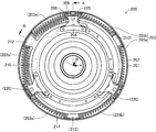
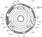
- FIG. 3 is a front view schematically showing a configuration of a lockup device in the torque converter shown in FIGS. 1 and 2, respectively.
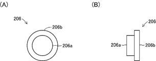
- FIGS. 1A and 1B show the external configuration of the receiving piece shown in FIGS. 1 to 3, respectively.
- FIG. 1A is a front view of the receiving piece
- FIG. 2B is a side view of the receiving piece.
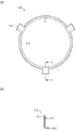
- (A) and (B) show the external configuration of the intermediate member shown in FIGS. 1 to 3, respectively.
- (A) is a front view of the intermediate member
- (B) shows C shown in (A).
- FIG. 10 is a cross-sectional view of the intermediate member as viewed from line -C.
- FIG. 4 is a front view schematically showing an operating state (twisted state of about 30 Nm) of the lockup device shown in FIG. 3.
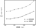
- FIG. 6 shows the results of a comparative experiment of His torque in a torque converter having a lock-up device according to the present invention and a torque converter according to the prior art, where the vertical axis is the His torque and the horizontal axis is the engine speed.
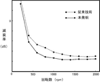
- the comparative experiment result of the damping performance in the torque converter provided with the lock-up device according to the present invention and the torque converter according to the prior art is shown, where the vertical axis is the damping factor and the horizontal axis is the engine speed. It is the side view which showed roughly the external appearance structure of the receiving piece which concerns on the modification of this invention.
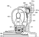
- FIG. 1 is a cross-sectional view schematically showing a configuration of a torque converter 100 including a lockup device 200 according to the present invention. 1 corresponds to a cross-sectional view of the torque converter 100 as seen from the line AA shown in FIG.
- FIG. 2 is a cross-sectional view schematically showing a configuration of the torque converter 100 including the lockup device 200 according to the present invention in a cross section different from that of FIG. 2 corresponds to a cross-sectional view of the torque converter 100 as seen from the line BB shown in FIG.
- FIG. 1 is a cross-sectional view schematically showing a configuration of a torque converter 100 including a lockup device 200 according to the present invention. 1 corresponds to a cross-sectional view of the torque converter 100 as seen from the line AA shown in FIG.
- FIG. 2 is a cross-sectional view schematically showing a configuration of the torque converter 100 including the lockup device 200 according to the present invention in a cross section different from that of FIG. 2 corresponds to a cross
- the torque converter 100 is a mechanical device that is provided between an engine and a transmission mainly in an automobile (so-called AT car) that includes an automatic transmission, and amplifies the driving force of the engine and transmits it to the transmission.
- AT car a transmission mainly in an automobile
- the torque converter 100 includes a torque converter cover 101.
- the torque converter cover 101 is a component that is rotationally driven by a driving force from a vehicle engine (not shown), and is formed in a substantially cup shape in which the edge of the disk is bent and extended.
- the torque converter cover 101 is connected to a crankshaft (not shown) whose rear surface (right side surface in the figure) extends from the engine via a connecting part 101a, and a pump impeller 102 is provided at a bent edge.
- the pump impeller 102 is an impeller that is rotated integrally with the torque converter cover 101 and sends hydraulic oil (not shown) to the turbine runner 103.
- the pump impeller 102 is fixedly attached to the torque converter cover 101 and is relatively rotated with respect to the stator 105. It is attached as possible.
- the turbine runner 103 is an impeller that is rotated by the flow of hydraulic oil by the rotational drive of the pump impeller 102, and is provided in a state of being opposed to the pump impeller 102 and relatively rotatable.
- the turbine runner 103 is spline-fitted to an output shaft 104 extending from a transmission (not shown) and is attached to the stator 105 so as to be relatively rotatable.
- the stator 105 is an impeller that rectifies the flow of hydraulic oil flowing back from the turbine runner 103 and sends it to the pump impeller 101.
- the stator 105 is provided with a one-way clutch 107 for the stator shaft 106 that is supported by the transmission in a non-rotatable state. Is attached through.
- the one-way clutch 107 is a component that supports the stator 105 so as to be rotatable only in the same direction as the rotation direction of the turbine runner 103, and is spline-fitted onto the stator shaft 106.
- a lockup device 200 is provided between the torque converter cover 101 and the turbine runner 103.
- the lockup device 200 is a mechanical device for directly connecting the pump impeller 102 and the turbine runner 103 without using hydraulic oil, and includes a clutch piston 201.
- the clutch piston 201 is a part for bringing the turbine runner 103 into a connected state or a non-connected state with respect to the torque converter cover 101 formed integrally with the pump impeller 102. It is formed in a substantially tray shape.
- the clutch piston 201 is slidably fitted on the cylindrical portion of the turbine runner 103 that is spline-fitted to the output shaft 104 so as to be displaced within a range in contact with or away from the inner surface of the torque converter cover 101. And is supported. Further, the outer edge portion of the clutch piston 201 is formed such that the plate surface on the torque converter cover 101 side protrudes toward the inner surface of the torque converter cover 101 and the plate surface on the turbine runner 103 side is recessed in a concave shape.
- a friction material 201a is provided at a portion protruding toward the inner surface of the torque converter cover 101, and a damper spring 203 is provided through a guide blade 202 at the concave portion. .
- the guide plate 202 is a metal part that is disposed between the damper spring 203 and the inner surface of the clutch piston 201 to prevent frictional contact therebetween and to improve the stretchability of the damper spring 203.
- the ring body corresponding to the circumferential direction of 201 is configured by three curved piece-like bodies obtained by equally dividing the ring body into three.
- the guide plate 202 has a substantially L-shaped cross section corresponding to a corner on the inner surface of the clutch piston 201.
- the damper spring 203 is a component that transmits to the turbine runner 103 while attenuating fluctuations in rotational driving force (torque) transmitted from the engine via the torque converter cover 101, and is configured by a steel coil spring.
- two damper springs 203 a and 203 b are arranged via an intermediate member 210 between three damper holders 204 provided on the surface of the turbine runner 103 side.
- the damper holder 204 is a part for receiving both end portions of the damper spring 203 constituted by a pair of damper springs 203a and 203b and for projecting the central portion of the damper spring 203 to the inside of the clutch piston 201 in the radial direction. 201 extends from the inside in the radial direction toward the outside. More specifically, the damper holder 204 is attached to the inner side in the radial direction than the part where the damper spring 203 is disposed in the clutch piston 201, and the damper pressing part 205 extends from the attachment part toward the outer side in the radial direction. ing.
- the damper pressing portion 205 is a portion in which both end portions of the damper spring 203 are in contact with each other via the receiving piece 206, and the radially outer portion of the clutch piston 201 in the damper pressing portion 205 is in relation to the radially inner portion. It is formed to project to the damper spring 203 side. In other words, the damper pressing portion 205 is formed so that the circumferential width of the clutch piston 201 increases toward the radially outer side of the clutch piston 201. Further, the damper pressing portion 205 is formed to be recessed toward the clutch piston 201 so that a connecting body, which will be described later, can be displaced along the circumferential direction of the clutch piston 201.
- the receiving piece 206 is a component that is fitted into each end of each of the damper springs 203 a and 203 b that constitute the damper spring 203, and a fitting portion 206 a that fits into the hole of the damper spring 203. It is composed of two cylindrical portions with an end face contact portion 206b addressed to the end portion of the damper spring 203.
- the intermediate member 210 is a metal part that regulates the movement and deformation of the damper spring 203a and the damper spring 203b.
- a portion 212 and an overhang portion 213 are provided.
- the main body ring portion 211 is a portion that is slidably attached radially inward from the portion of the clutch piston 201 where the damper spring 203 is disposed, and is formed in a ring shape.
- a damper pressing portion 212 is formed so as to project radially outward at a position that divides the main body ring portion 211 into three equal parts, and between these three damper pressing portions 212.
- the outer peripheral portion of each is bent toward the inner surface side of the clutch piston 201 to form an overhang portion 213.
- the damper pressing portion 212 is a portion where the mutually facing ends of the damper spring 203a and the damper spring 203b are in contact with each other via the receiving piece 206, and the outer side in the radial direction of the clutch piston 201 This portion is formed to protrude toward the damper spring 203 with respect to the inner portion in the same radial direction.
- the damper pressing portion 212 is formed so that the circumferential width of the clutch piston 201 increases toward the radially outer side of the clutch piston 201.
- the damper pressing portion 212 is disposed between the damper spring 203a and the damper spring 203b and connects the damper springs 203a and the damper springs 203b in series.
- the damper spring 203a and the damper spring 203b sandwiched between the damper pressing portion 205 and the damper pressing portion 212 are deformed so that each central portion protrudes radially inward of the clutch piston 201 with respect to both ends.
- the damper pressing portion 205 and the damper pressing portion 212 correspond to a pair of damper pressing portions according to the present invention.
- the overhanging portion 213 receives the central portions of the damper springs 203a and 203b that have received the force projecting inward in the radial direction of the clutch piston 201 by the damper pressing portion 205 and the damper pressing portion 212, and is displaced inward in the same radial direction. It is a portion that restricts deformation, and is bent and extended from the main body ring portion 211 with a protruding amount for receiving the side portions of the damper springs 203a and 203b.
- the overhanging amount of the overhanging portion 213 is such that at least the damper springs 203a and 203b are deformed and arranged in an arc shape along the circumferential direction of the clutch piston 201. It is set to an amount projecting radially outward from the inner peripheral side surface of 203b. In the present embodiment, the overhanging portion 213 is set to an overhanging amount that can contact the side surface portions of the respective center portions of the damper springs 203a and 203b even when the clutch piston 201 is rotationally driven at a speed of 1500 rpm. Yes.
- the outer diameter of the main body ring portion 211 in this embodiment is a circular shape having a diameter that can contact the side surface portions of the respective center portions of the damper springs 203a and 203b even when the clutch piston 201 is rotationally driven at a speed of 1500 rpm. Is formed.
- the intermediate member 210 is attached in a state in which the main body ring portion 211 is slidable in the circumferential direction on the clutch piston 201 so that the damper pressing portion 212 is positioned in the middle of the three damper holders 204 in the circumferential direction.
- the damper springs 203a and 203b are pressed at both ends by the damper pressing portion 205 and the damper pressing portion 212, and the central portion is displaced and / or deformed radially inward of the clutch piston 201 to form the overhanging portion 213.
- the clutch piston 201 is accommodated in a pressed state.
- a cover 214 for covering the intermediate member 210 and a part of the damper spring 203 on the intermediate member 210 between the three damper holders 204 and holding the intermediate member 210 in a slidable state is provided. It is attached.
- one of the three covers 214 is indicated by a two-dot chain line in order to clarify the configuration inside the cover 214.
- the connecting body 220 is a metal part for connecting the turbine runner 103 to the clutch piston 201, and is formed in a plate shape extending from the outer peripheral portion of the turbine runner 103.
- the distal end portion of the coupling body 220 extends into the damper pressing portion 212 of the damper holder 204 and is in contact with one end portion of the damper spring 203a.
- the distal end portion of the coupling body 220 is formed so as to contact a portion on the radially outer side of the clutch piston 201 with respect to the axis line of the damper spring 203a via the receiving piece 206.
- the connecting body 220 can be deformed so that the center portion projects outwardly in the radial direction of the clutch piston 201 with respect to both ends, similarly to the damper pressing portions 205 and 212. it can. That is, in this embodiment, the front-end
- This torque converter 100 functions by being disposed between an engine and a transmission in a so-called AT vehicle. Specifically, in the torque converter 100, first, the rotational drive force of the engine is transmitted to the torque converter cover 101 by the release of the brake and the depression of the accelerator pedal by the driver of the vehicle, and the torque converter cover 101 and the pump impeller 102 are integrated. Rotating drive. Next, in the torque converter 100, the turbine runner 103 is rotationally driven as the hydraulic oil in the torque converter 100 circulates. As a result, the vehicle starts traveling.
- the lock-up device 200 Attenuates the torque fluctuation by the expansion and contraction of the damper spring 203 according to the torque fluctuation from the engine. More specifically, the damper spring 203a of the pair of damper springs 203a and 203b constituting the damper spring 203 is sandwiched between the distal end portion of the coupling body 220 and the damper pressing portion 212 to be compressed and deformed, and the damper spring 203b. Is compressed between the damper pressing portion 212 and the damper pressing portion 205.
- the damper spring 203a is displaced radially outwardly of the clutch piston 201 because the central portion of the damper spring 203a and the damper pressing portion 212 project toward the overhang portion 213 and are pressed against the overhang portion 213. Or deformation is regulated. Further, the damper spring 203b has a central portion that protrudes toward the overhanging portion 213 and is pressed against the overhanging portion 213 by the damper pressing portion 212 and the damper pressing portion 205, so that the clutch piston 201 is displaced or deformed outward in the radial direction. Be regulated.
- the lock-up device 200 prevents the damper springs 203a and 203b from coming into contact with the inner peripheral surface of the clutch piston 201 due to the rotational drive of the clutch piston 201, thereby increasing the hysteresis torque.
- the experimental results by the present inventor will be described.
- the inventor conducted a comparative experiment of the hysteresis torque and the damping performance of the damper spring 203 in the lockup device 200 in the present embodiment and the conventional lockup device.
- the conventional lockup device is configured by arranging a damper spring 203 curved in an arc shape along the circumferential direction inside the clutch piston 201.
- both end portions of the damper spring 203 are sandwiched between damper pressing portions parallel to the both end portions, and the center portion of the damper spring 203 is not supported by the intermediate member 210.
- the connecting body extending from the turbine runner 103 has a tip portion facing the axis of the damper spring 203.
- FIG. 7 is a comparative graph of the hysteresis torque between the lockup device 200 in the present embodiment and the conventional lockup device, where the vertical axis is the amount of historque and the horizontal axis is the rotational speed of the clutch piston 201.
- FIG. 8 is a comparison graph of the damping performance between the lockup device 200 of the present embodiment and the conventional lockup device, where the vertical axis is the damping rate of the variable torque, and the horizontal axis is the rotational speed of the clutch piston 201. is there.
- the lockup device 200 in the present embodiment can obviously reduce the hysteresis torque and can attenuate the torque fluctuation as compared with the conventional lockup device.
- the lock-up device 200 includes the damper pressing portions 205 and 212 and the connecting body 220 at the center portion of the damper spring 203 as the overhang portion 213 of the intermediate member 210. Due to the pressing, the displacement and deformation of the damper spring 203 to the outside in the radial direction when the clutch piston 201 is driven to rotate are suppressed. Thereby, the lockup device 200 can suppress the generation of the His torque due to the friction between the damper spring 203 and the clutch piston 201, and can improve the damping performance of the engine torque fluctuation. In particular, it is effective to use a low spring constant damper spring 203 to effectively attenuate engine torque fluctuations.
- the low spring constant damper spring 203 is moved toward the clutch piston 201 by buckling during contraction. Are also easily deformed. However, according to the lockup device 200 according to the present invention, the deformation toward the clutch piston 201 can be effectively suppressed even in the damper spring 203 having a low spring constant.
- the lock-up device 200 is configured so that the radially outer portion of the clutch piston 201 has the same radial direction at each contact portion of the damper pressing portions 205 and 212 that sandwich the damper spring 203 from both ends. It was formed so as to protrude toward the damper spring 201 side (in other words, in the circumferential direction) with respect to the inner portion.
- the damper pressing portions 205 and 212 need only be able to apply a force that causes the central portion of the damper spring 203 to project outward in the radial direction of the clutch piston 201. Therefore, the damper pressing portions 205 and 212 are disposed at both ends of the damper springs 203a and 203b. What is necessary is just to form so that the radial direction outer side part in the clutch piston 201 may protrude over the damper spring 201 side with respect to the same radial direction inner part about at least one of the damper pressing parts 205 and 212.
- the coupling body 220 is disposed so as to press the portion on the radially outer side of the clutch piston 201 with respect to the damper spring 203a with respect to the axial line, so that the central portion of the damper spring 203 is connected to the clutch piston 201. It is comprised so that it may protrude toward the radial inside. Therefore, the damper pressing portion according to the present invention can be configured by only the connecting body 220 in this embodiment instead of the damper pressing portions 205 and 212 in the above embodiment.
- the damper pressing portion according to the present invention can be configured by the receiving piece 206 instead of or in addition to the damper pressing portions 205 and 212 and the coupling body 220 in the above embodiment.
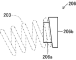
- the receiving piece 206 is configured such that the thickness of the end face contact portion 206 b changes from one end to the other between the end portions facing each other.
- the receiving piece 206 comprised in this way is attached in the direction which protrudes to the damper spring 201 side with respect to the part arrange
- the damper pressing parts 205 and 212 in the said embodiment can be expected.
- the damper spring 203 is indicated by a two-dot chain line.
- the overhang portion 213 is formed in a wall shape extending between the three damper pressing portions 212.
- the overhanging portion 213 only needs to be formed so as to be able to receive the damper spring 203 overhanging radially inward of the clutch piston 201. Therefore, the overhang portion 213 can be formed partially or intermittently on the main body ring portion 211.
- projection part 213 was comprised as an outer edge part of the main body ring part 211 formed in the ring shape.
- the projecting portion 213 can be formed to project from the outer edge portion of the main body ring portion 211 in a convex shape.
- damper pressing portion and the overhang portion are provided for each damper spring 203 (damper springs 203a and 203b). Therefore, the number of damper pressing portions and overhang portions to be formed is not necessarily limited to the above embodiment, and may be formed for each damper spring 203.
- the number of damper springs 203 (damper springs 203a and 203b), the number of damper holders 204, and the number of damper pressing portions 212 provided on the intermediate member are not limited to the above embodiment, and the specifications of the torque converter 100 are not limited. Of course, it may be provided as appropriate.
- 100 torque converter, DESCRIPTION OF SYMBOLS 101 ... Torcon cover, 101a ... Connection component, 102 ... Pump impeller, 103 ... Turbine runner, 104 ... Output shaft, 105 ... Stator, 106 ... Stator shaft, 107 ... One-way clutch, 200 ... lock-up device, DESCRIPTION OF SYMBOLS 201 ... Clutch piston, 201a ... Friction material, 202 ... Guide plate, 203, 203a, 203b ... Damper spring, 204 ... Damper holder, 205 ... Damper press part, 206 ... Receiving piece, 206a ... Fitting part, 206b ... End face contact part , 210 ... intermediate member 211 ... body ring part 212 ... damper pressing part 213 ... overhang part 214 ... cover 220 ... a connected body.
Landscapes
- Engineering & Computer Science (AREA)
- General Engineering & Computer Science (AREA)
- Mechanical Engineering (AREA)
- Physics & Mathematics (AREA)
- Acoustics & Sound (AREA)
- Aviation & Aerospace Engineering (AREA)
- Mechanical Operated Clutches (AREA)
- Control Of Fluid Gearings (AREA)
Abstract
【課題】ダンパスプリングとクラッチピストンとの摩擦によるヒストルクを抑制してエンジンのトルク変動の減衰性能を向上させることができるロックアップ装置およびトルクコンバータを提供する。 【解決手段】トルクコンバータ100は、ポンプインペラ102と一体的に回転するトルコンカバー101と出力軸104に連結されたタービンランナ103とを直結するロックアップ装置200を備えている。ロックアップ装置200は、トルコンカバー101に接触または離隔するクラッチクラッチピストン201内にダンパスプリング203を備えるとともに同ダンパスプリング203の内側に中間部材210を備えている。ダンパスプリング203は、両端部に宛がわれたダンパ押圧部205,213および連結部材220によって中央部がクラッチピストン201における径方向内側に張り出して中間部材220における張出部213に押し付けられている。
Description
エンジンからの駆動力を作動油を用いて増幅して出力軸側に伝達するトルクコンバータにおけるロックアップ装置および同ロックアップ装置を備えたトルクコンバータに関する。
従来から、主として自動変速機を備えた自走式車両(所謂AT車)においては、エンジンと変速機との間にトルクコンバータが設けられている。トルクコンバータは、互いに対向配置されたポンプインペラとタービンランナとの間で作動油が循環することによってエンジンからの駆動力を出力軸側に増幅して伝達する機械装置である。このトルクコンバータにおいては、車両の燃費効率を向上させる目的でロックアップ装置が設けられている。
ロックアップ装置は、ポンプインペラと一体的に回転駆動するトルコンカバーに対してタービンランナに連結されたクラッチピストンが接触または離隔するように構成されており、トルコンカバーに対してクラッチピストンが接触することによりポンプインペラとタービンランナとが直結されてポンプインペラ側の駆動力を直接タービンランナ側に伝達させている。
このロックアップ装置においては、クラッチピストンとタービンランナとの間にエンジンからの駆動力変動(「トルク変動」ともいう)を減衰するためにコイル状のダンパスプリングが設けられている。例えば、下記特許文献1には、互いに直列配置されたダンパスプリングをリング状に形成された中間部材における中間支持部を介して連結することによってピストン部材(クラッチピストンに相当)の径方向外側へのダンパスプリングの移動を規制したロックアップダンパー機構(ロックアップ装置に相当)が開示されている。
しかしながら、上記特許文献1に記載されたロックアップダンパー機構においては、中間支持部によって互いに連結されたダンパスプリングが全体として径方向外側に移動することはある程度規制することができるが、中間支持部によって互いに連結される個々のダンパスプリングについては何ら規制されていないため依然として径方向外側に移動してピストン部材との摩擦によってヒストルクを増大させてエンジンのトルク変動の減衰性能が低下するという問題がある。
本発明は上記問題に対処するためなされたもので、その目的は、ダンパスプリングとクラッチピストンとの摩擦によるヒストルクを抑制してエンジンのトルク変動の減衰性能を向上させることができるロックアップ装置およびトルクコンバータを提供することにある。
上記目的を達成するため、本発明の特徴は、エンジンの駆動力によって回転駆動するポンプインペラに接触または離隔可能に支持された円盤状のクラッチピストンと、クラッチピストンに周方向に沿って配置されてコイル状のダンパスプリングと、ポンプインペラに作動油を介して対向配置されるタービンランナに対してクラッチピストンをダンパスプリングを介して連結する連結体とを有するロックアップ装置において、ダンパスプリングを両端部から挟んでダンパスプリングの中央部がクラッチピストンにおける径方向内側に向かって張り出すように押す一対のダンパ押圧部と、ダンパスプリングの中央部におけるクラッチピストンにおける径方向内側の側面よりも同径方向外側に張り出す張出部が形成された中間部材とを備えたことにある。なお、この場合、クラッチピストンは、ポンプインペラに対して直接接触する場合のほか、ポンプインペラと一体的に回転駆動する部材(例えば、トルコンカバー)を介して間接的に接触する場合を含むものである。
このように構成した本発明の特徴によれば、ロックアップ装置は、ダンパ押圧部がダンパスプリングの中央部を中間部材の張出部に押し付けているため、クラッチピストンの回転駆動時におけるダンパスプリングの径方向外側への変位および変形が抑制される。これにより、ロックアップ装置は、ダンパスプリングとクラッチピストンとの摩擦によるヒストルクの発生を抑制してエンジンのトルク変動の減衰性能を向上させることができる。特に、エンジンのトルク変動を効果的に減衰させるには、低バネ定数のダンパスプリングを用いることが有効であるが、低バネ定数のダンパスプリングは収縮時の座屈によってクラッチピストン側にも変形し易い。しかし、本発明に係るロックアップ装置によれば、低バネ定数のダンパスプリングにおいても効果的にクラッチピストン側への変形を抑制することができる。
また、本発明の他の特徴は、前記ロックアップ装置において、前記一対のダンパ押圧部における少なくとも一方は、クラッチピストンにおける径方向外側部分が同径方向内側部分に対してダンパスプリング側に張り出して形成されていることにある。
このように構成した本発明の他の特徴によれば、ロックアップ装置は、一対のダンパ押圧部における少なくとも一方がクラッチピストンにおける径方向外側部分が同径方向内側部分に対してダンパスプリング側に張り出して形成されているため、ダンパスプリングを精度良くクラッチピストンの径方向内側に向かって張り出すように押すことができる。なお、一対のダンパ押圧部は、少なくとも一方が、ダンパスプリングにおける軸線よりもクラッチピストンの径方向外側の部分にのみ接触するように構成することもできる。
また、本発明の他の特徴は、前記ロックアップ装置は、中間部材は、クラッチピストンの回転数が少なくとも1500rpmに達するまでの間、ダンパスプリングの中央部におけるクラッチピストンにおける径方向内側の側面よりも張出部が同径方向外側に張り出す張り出し量で形成されていることにある。
このように構成した本発明の他の特徴によれば、ロックアップ装置は、クラッチピストンの回転数が少なくとも1500rpm(1500rpm未満であっても実質的に1500rpmと見做すことができる回転数を含む)に達するまでの間におけるダンパスプリングの中央部の径方向内側の側面よりも中間部材の張出部が同径方向外側に張り出すように形成されているため、エンジンの低回転域におけるトルク変動の減衰性能を向上させることができる。
また、本発明の他の特徴は、前記ロックアップ装置において、中間部材は、張出部がダンパスプリングの側面に沿って延びる壁状に形成されていることにある。
このように構成した本発明の他の特徴によれば、ロックアップ装置は、中間部材の張出部がダンパスプリングの側面に沿って延びる壁状に形成されているため、ダンパスプリング収縮時においても精度良くダンパスプリングの側面を受け止めることができる。
また、本発明は、ロックアップ装置の発明として実施できるばかりでなく、このロックアップ装置を備えたトルクコンバータの発明としても実施できるものである。
具体的には、トルクコンバータは、エンジンの駆動力によって回転駆動するポンプインペラと、ポンプインペラに対向する位置に回転駆動可能な状態で配置されるタービンランナと、ポンプインペラとタービンランナとの間に設けられる作動油とを備えたトルクコンバータにおいて、請求項1ないし請求項4のうちのいずれか1つに記載したロックアップ装置を備えるとよい。このように構成したトルクコンバータにおいては、前記ロックアップ装置と同様の作用効果を期待することができる。
以下、本発明に係るロックアップ装置および同ロックアップ装置を備えたトルクコンバータの一実施形態について図面を参照しながら説明する。図1は、本発明に係るロックアップ装置200を備えたトルクコンバータ100の構成を概略的に示す断面図である。なお、この図1は、図3に示すA-A線から見たトルクコンバータ100の断面図に相当する。図2は、本発明に係るロックアップ装置200を備えたトルクコンバータ100の構成を図1とは異なる断面で概略的に示す断面図である。なお、この図2は、図3に示すB-B線から見たトルクコンバータ100の断面図に相当する。図3は、図1および図2にそれぞれ示すトルクコンバータ100内におけるロックアップ装置200の正面図である。このトルクコンバータ100は、主として自動変速機を備えた自動車(所謂AT車)において、エンジンと変速機との間に設けられてエンジンの駆動力を増幅して変速機に伝達する機械装置である。
(トルクコンバータ100の構成)
トルクコンバータ100は、トルコンカバー101を備えている。トルコンカバー101は、図示しない車両のエンジンからの駆動力によって回転駆動する部品であり、円盤の縁部が屈曲して延びる略カップ状に形成されている。このトルコンカバー101は、背面(図示右側側面)がエンジンから延びる図示しないクランクシャフトに対して連結部品101aを介して連結されるとともに、屈曲した縁部にポンプインペラ102が設けられている。
トルクコンバータ100は、トルコンカバー101を備えている。トルコンカバー101は、図示しない車両のエンジンからの駆動力によって回転駆動する部品であり、円盤の縁部が屈曲して延びる略カップ状に形成されている。このトルコンカバー101は、背面(図示右側側面)がエンジンから延びる図示しないクランクシャフトに対して連結部品101aを介して連結されるとともに、屈曲した縁部にポンプインペラ102が設けられている。
ポンプインペラ102は、トルコンカバー101と一体的に回転駆動して図示しない作動油をタービンランナ103に送る羽根車であり、トルコンカバー101に対して固定的に取り付けられるとともにステータ105に対して相対回転可能に取り付けられている。タービンランナ103は、ポンプインペラ102の回転駆動による作動油の流動によって回転する羽根車であり、ポンプインペラ102に対して対向するとともに相対回転可能な状態で設けられている。具体的には、タービンランナ103は、図示しない変速機(トランスミッション)から延びる出力軸104にスプライン嵌合するとともに、ステータ105に対して相対回転可能に取り付けられている。
ステータ105は、タービンランナ103から還流する作動油の流れを整流してポンプインペラ101に送る羽根車であり、前記変速機に回転不能な状態で支持されたステータシャフト106に対してワンウェイクラッチ107を介して取り付けられている。ワンウェイクラッチ107は、ステータ105をタービンランナ103の回転方向と同じ方向にのみ回転可能に支持する部品であり、ステータシャフト106上にスプライン嵌合している。
トルコンカバー101とタービンランナ103との間には、ロックアップ装置200が設けられている。ロックアップ装置200は、ポンプインペラ102とタービンランナ103とを作動油を介さずに直結するための機械装置であり、クラッチピストン201を備えている。クラッチピストン201は、ポンプインペラ102と一体的に形成されたトルコンカバー101に対してタービンランナ103を連結状態または非連結状態にするための部品であり、円盤の縁部が屈曲して延びる円形の略トレー状に形成されている。
このクラッチピストン201は、トルコンカバー101の内表面に対して接触または離隔する範囲で変位するように出力軸104にスプライン嵌合するタービンランナ103の筒状部上に摺動可能な状態で嵌合して支持されている。また、このクラッチピストン201における外縁部分は、トルコンカバー101側の板面がトルコンカバー101の内表面に向かって突出するとともに、タービンランナ103側の板面が凹状に凹んでそれぞれ形成されている。そして、クラッチピストン201は、前記トルコンカバー101の内表面に向かって突出する部分に摩擦材201aが設けられるとともに、前記凹状に凹んだ部分にダンパスプリング203がガイドブレード202を介して設けられている。
ガイドプレート202は、ダンパスプリング203とクラッチピストン201の内表面との間に配置されて両者の摩擦接触を防止するとともにダンパスプリング203の伸縮性を向上させるための金属製の部品であり、クラッチピストン201の周方向に対応するリング体を均等に3分割した3つの湾曲した片状体で構成されている。このガイドプレート202は、断面形状がクラッチピストン201の内表面における隅部に対応する略L字状に形成されている。
ダンパスプリング203は、エンジンからトルコンカバー101を介して伝達される回転駆動力(トルク)変動を減衰しながらタービンランナ103に伝達する部品であり、鋼製のコイルスプリングによって構成されている。このダンパスプリング203は、タービンランナ103側の表面に設けられた3つのダンパホルダ204の各間にそれぞれ2つずつのダンパスプリング203a,203bが中間部材210を介して配置されている。
ダンパホルダ204は、一対のダンパスプリング203a,203bによって構成されたダンパスプリング203の両端部を受け止めるとともにダンパスプリング203の中央部をクラッチピストン201の径方向内側に張り出させるための部品であり、クラッチピストン201の径方向内側から外側に向かって延びて形成されている。より具体的には、ダンパホルダ204は、クラッチピストン201におけるダンパスプリング203が配置された部分より径方向内側に取り付けられるとともに、同取付部分から径方向外側に向かってダンパ押圧部205が延びて形成されている。
ダンパ押圧部205は、ダンパスプリング203の両端部がそれぞれ受け片206を介して接触する部分であり、ダンパ押圧部205におけるクラッチピストン201の径方向外側の部分が同径方向内側の部分に対してダンパスプリング203側に張り出して形成されている。換言すれば、ダンパ押圧部205は、クラッチピストン201の径方向外側に向かってクラッチピストン201の周方向の幅が広がって形成されている。また、このダンパ押圧部205は、後述する連結体がクラッチピストン201の周方向に沿って変位可能とするためにクラッチピストン201側に凹んで形成されている。
受け片206は、図4に示すように、ダンパスプリング203を構成する各ダンパスプリング203a,203bの各両端部に嵌め込まれる部品であり、ダンパスプリング203の孔内に嵌合する嵌合部206aとダンパスプリング203の端部に宛がわれる端面当て部206bとの2つの円柱部で構成されている。
中間部材210は、図5(A),(B)にそれぞれ示すように、ダンパスプリング203aおよびダンパスプリング203bの移動および変形を規制する金属製の部品であり、主として、本体環部211、ダンパ押圧部212および張出部213を備えて構成されている。これらのうち、本体環部211は、クラッチピストン201におけるダンパスプリング203が配置された部分より径方向内側に摺動可能に取り付けられる部分であり、リング状に形成されている。この本体環部211の外周部には、この本体環部211を3等分する位置にダンパ押圧部212が径方向外側に向かって張り出して形成されるとともに、これら3つの各ダンパ押圧部212間における外周部がクラッチピストン201の内表面側に屈曲して張出部213がそれぞれ形成されている。
ダンパ押圧部212は、前記ダンパ押圧部205と同様に、ダンパスプリング203aおよびダンパスプリング203bにおける互いに対向し合う端部がそれぞれ受け片206を介して接触する部分であり、クラッチピストン201における径方向外側の部分が同径方向内側の部分に対してダンパスプリング203側に張り出して形成されている。換言すれば、ダンパ押圧部212は、クラッチピストン201の径方向外側に向かってクラッチピストン201の周方向の幅が広がって形成されている。
このダンパ押圧部212は、ダンパスプリング203aとダンパスプリング203bとの間に配置されて各ダンパスプリング203aとダンパスプリング203bとを直列に連結する。これにより、これらのダンパ押圧部205とダンパ押圧部212とによって挟まれたダンパスプリング203aおよびダンパスプリング203bは、各中央部が両端部に対してクラッチピストン201の径方向内側に張り出すように変形する。すなわち、これらのダンパ押圧部205およびダンパ押圧部212が、本発明に係る一対のダンパ押圧部に相当する。
張出部213は、ダンパ押圧部205およびダンパ押圧部212によってクラッチピストン201の径方向内側に張り出す力を受けたダンパスプリング203a,203bの各中央部を受け止めて同径方向内側への変位および変形を規制する部分であり、これらのダンパスプリング203a,203bの各側面部を受ける止める突出量で本体環部211から屈曲して延びている。
この張出部213の張り出し量は、張出部213が存在しない場合において、少なくともダンパスプリング203a,203bをクラッチピストン201の周方向に沿って円弧状に変形させて配置した際におけるダンパスプリング203a,203bの内周側側面よりも径方向外側に張り出す量に設定されている。本実施形態においては、張出部213は、クラッチピストン201が1500rpmの速さで回転駆動した場合においてもダンパスプリング203a,203bの各中央部の側面部に接することができる張り出し量に設定されている。すなわち、本実施形態における本体環部211の外径は、クラッチピストン201が1500rpmの速さで回転駆動した場合においてもダンパスプリング203a,203bの各中央部の側面部に接することができる直径の円形に形成されている。
この中間部材210は、ダンパ押圧部212が周方向において3つのダンパホルダ204の中間に位置するように本体環部211がクラッチピストン201上に周方向に摺動可能な状態で取り付けられる。これにより、ダンパスプリング203a,203bは、各両端部がダンパ押圧部205およびダンパ押圧部212によって押されて中央部がクラッチピストン201の径方向内側に変位および/または変形して張出部213に押し付けられた状態でクラッチピストン201内に収容される。
また、クラッチピストン201上には、3つのダンパホルダ204間の中間部材210上に中間部材210およびダンパスプリング203の一部を覆って中間部材210を摺動可能な状態で保持するためのカバー214が取り付けられている。なお、図1においては、カバー214の内側の構成を明確にするために、3つのカバー214のうちの1つを二点鎖線で示している。
連結体220は、クラッチピストン201に対してタービンランナ103を連結するための金属製の部品であり、タービンランナ103の外周部から延びる板状に形成されている。この連結体220の先端部は、ダンパホルダ204におけるダンパ押圧部212内に延びてダンパスプリング203aの一方の端部に接触している。この場合、連結体220の先端部は、ダンパスプリング203aにおける軸線よりもクラッチピストン201の径方向外側の部分に受け片206を介して接触するように形成されている。これにより、連結体220は、ダンパスプリング203aを押圧した際、ダンパ押圧部205,212と同様に、中央部を両端部に対してクラッチピストン201の径方向内側に張り出すように変形させることができる。すなわち、本実施形態においては、連結体220における先端部は、本発明に係るダンパ押圧部に相当する。
(トルクコンバータ100の作動)
次に、上記のように構成したトルクコンバータ100の作動について説明する。このトルクコンバータ100は、所謂AT車においてエンジンと変速機との間に配置されて機能する。具体的には、トルクコンバータ100は、まず、車両の運転者によるブレーキの解除およびアクセルペダルの踏み込みによってエンジンの回転駆動力がトルコンカバー101に伝達されてトルコンカバー101およびポンプインペラ102が一体的に回転駆動する。次いで、トルクコンバータ100は、トルクコンバータ100内の作動油が循環することによりタービンランナ103が回転駆動する。これにより、車両は走行を開始する。
次に、上記のように構成したトルクコンバータ100の作動について説明する。このトルクコンバータ100は、所謂AT車においてエンジンと変速機との間に配置されて機能する。具体的には、トルクコンバータ100は、まず、車両の運転者によるブレーキの解除およびアクセルペダルの踏み込みによってエンジンの回転駆動力がトルコンカバー101に伝達されてトルコンカバー101およびポンプインペラ102が一体的に回転駆動する。次いで、トルクコンバータ100は、トルクコンバータ100内の作動油が循環することによりタービンランナ103が回転駆動する。これにより、車両は走行を開始する。
この後、トルクコンバータ100は、トルコンカバー101とクラッチピストン201との間の領域の圧力が減じられてクラッチピストン201がトルコンカバー101側に変位してこのトルコンカバー101の内表面に強く押し付けられる。これにより、トルコンカバー101に連結されたクラッチピストン201に対してタービンランナ103がダンパスプリング203および連結体220をそれぞれ介して直結される。すなわち、トルクコンバータ100は、ロックアップ装置200によってポンプインペラ102とタービンランナ103とが直結される(以後、「ロックアップ状態」という)。
このロックアップ状態においては、エンジンからのトルク変動はダンパスプリング203によって減衰される。すなわち、ロックアップ装置200は、図6に示すように、エンジンからのトルク変動に応じてダンパスプリング203が伸縮することによってトルク変動を減衰する。より具体的には、ダンパスプリング203を構成する一対のダンパスプリング203a,203bのうちのダンパスプリング203aが連結体220の先端部とダンパ押圧部212とに挟まれて圧縮変形するとともに、ダンパスプリング203bがダンパ押圧部212とダンパ押圧部205とに挟まれて圧縮変形する。
この場合、ダンパスプリング203aは、連結体220の先端部およびダンパ押圧部212によって中央部が張出部213側に張り出して張出部213に押し付けられるため、クラッチピストン201の径方向外側への変位または変形が規制される。また、ダンパスプリング203bは、ダンパ押圧部212およびダンパ押圧部205によって中央部が張出部213側に張り出して張出部213に押し付けられるため、クラッチピストン201の径方向外側への変位または変形が規制される。これらにより、ロックアップ装置200は、クラッチピストン201の回転駆動によってダンパスプリング203a,203bがクラッチピストン201の内周面に接触してヒストルクが増大することが防止される。
ここで、本発明者による実験結果について説明する。本発明者は、本実施形態におけるロックアップ装置200と従来のロックアップ装置とにおいてヒストルクおよびダンパスプリング203の減衰性能の比較実験を行った。なお、従来のロックアップ装置とは、クラッチピストン201の内側に周方向に沿ってダンパスプリング203を円弧状に湾曲した状態で配置して構成されている。そして、従来のロックアップ装置は、ダンパスプリング203の各両端部は同各両端部に平行なダンパ押圧部によって挟まれるとともに、ダンパスプリング203の中央部は中間部材210による支持はない。また、タービンランナ103から延びる連結体は、先端部がダンパスプリング203の軸線上に対向している。
図7は、本実施形態におけるロックアップ装置200と従来のロックアップ装置とにおけるヒストルクの比較グラフであり、縦軸がヒストルク量であり横軸がクラッチピストン201の回転数である。また、図8は、本実施形態におけるロックアップ装置200と従来のロックアップ装置とにおける減衰性能の比較グラフであり、縦軸が変動トルクの減衰率であり横軸がクラッチピストン201の回転数である。これらの図4および図5によれば、本実施形態におけるロックアップ装置200は、従来のロックアップ装置に比べて明らかにヒストルクを低減できるとともにトルク変動を減衰することができる。
上記作動説明からも理解できるように、上記実施形態によれば、ロックアップ装置200は、ダンパ押圧部205,212および連結体220がダンパスプリング203の中央部を中間部材210の張出部213に押し付けているため、クラッチピストン201の回転駆動時におけるダンパスプリング203の径方向外側への変位および変形が抑制される。これにより、ロックアップ装置200は、ダンパスプリング203とクラッチピストン201との摩擦によるヒストルクの発生を抑制してエンジンのトルク変動の減衰性能を向上させることができる。特に、エンジンのトルク変動を効果的に減衰させるには、低バネ定数のダンパスプリング203を用いることが有効であるが、低バネ定数のダンパスプリング203は収縮時の座屈によってクラッチピストン201側にも変形し易い。しかし、本発明に係るロックアップ装置200によれば、低バネ定数のダンパスプリング203においても効果的にクラッチピストン201側への変形を抑制することができる。
さらに、本発明の実施にあたっては、上記実施形態に限定されるものではなく、本発明の目的を逸脱しない限りにおいて種々の変更が可能である。なお、各変形例の説明においては、上記実施形態と同様の部分については同じ符号を付している。
例えば、上記実施形態においては、ロックアップ装置200は、ダンパスプリング203を両端部から挟むダンパ押圧部205,212のダンパスプリング203への各接触部についてクラッチピストン201における径方向外側部分が同径方向内側部分に対してダンパスプリング201側(換言すれば、周方向)に張り出すように形成した。しかし、ダンパ押圧部205,212は、ダンパスプリング203の中央部がクラッチピストン201における径方向内側に向かって張り出させる力を付与できればよいため、各ダンパスプリング203a,203bにおいて両端部に配置されるダンパ押圧部205,212の少なくとも一方についてクラッチピストン201における径方向外側部分が同径方向内側部分に対してダンパスプリング201側に張り出すように形成すればよい。
また、上記実施形態においては、連結体220をダンパスプリング203aに対して軸線よりもクラッチピストン201の径方向外側の部分を押圧するように配置することにより、ダンパスプリング203の中央部がクラッチピストン201における径方向内側に向かって張り出すように構成している。したがって、本発明に係るダンパ押圧部は、上記実施形態におけるダンパ押圧部205,212に代えて本実施形態における連結体220のみで構成することもできる。
また、本発明に係るダンパ押圧部は、上記実施形態におけるダンパ押圧部205,212および連結体220に代えてまたは加えて受け片206によって構成することもできる。具体的には、受け片206は、例えば、図9に示すように、端面当て部206bの厚さを互いに対向する端部間で一方から他方に向かって変化するように構成する。そして、このように構成した受け片206をクラッチピストン201における径方向外側に配置される部分が同径方向内側に配置される部分に対してダンパスプリング201側に張り出す向きで取り付ける。これによっても、上記実施形態におけるダンパ押圧部205,212と同様の作用効果を期待することができる。なお、図9においては、ダンパスプリング203を二点鎖線で示している。
また、上記実施形態においては、張出部213は、3つのダンパ押圧部212間に延びる壁状に形成した。しかし、張出部213は、クラッチピストン201の径方向内側に張り出すダンパスプリング203を受け止めることができるように形成されていればよい。したがって、張出部213は、本体環部211上において部分的または断続的に形成することもできる。また、上記実施形態においては、張出部213は、リング状に形成した本体環部211の外縁部として構成した。しかし、張出部213は、本体環部211の外縁部から凸状に張り出した形成することもできる。
また、本発明に係るダンパ押圧部および張出部は、ダンパスプリング203(ダンパスプリング203a,203b)ごとに設けられるものである。したがって、ダンパ押圧部および張出部を形成する数は、必ずしも上記実施形態に限定されるものではなく、ダンパスプリング203ごとに形成するようにすればよい。なお、ダンパスプリング203(ダンパスプリング203a,203b)を設ける数、ダンパホルダ204を設ける数および中間部材にダンパ押圧部212を設ける数は、上記実施形態に限定されるものではなく、トルクコンバータ100の仕様に応じて適宜設ければよいことは当然である。
100…トルクコンバータ、
101…トルコンカバー、101a…連結部品、102…ポンプインペラ、103…タービンランナ、104…出力軸、105…ステータ、106…ステータシャフト、107…ワンウェイクラッチ、
200…ロックアップ装置、
201…クラッチピストン、201a…摩擦材、202…ガイドプレート、203,203a,203b…ダンパスプリング、204…ダンパホルダ、205…ダンパ押圧部、206…受け片、206a…嵌合部、206b…端面当て部、
210…中間部材、211…本体環部、212…ダンパ押圧部、213…張出部、214…カバー、
220…連結体。
101…トルコンカバー、101a…連結部品、102…ポンプインペラ、103…タービンランナ、104…出力軸、105…ステータ、106…ステータシャフト、107…ワンウェイクラッチ、
200…ロックアップ装置、
201…クラッチピストン、201a…摩擦材、202…ガイドプレート、203,203a,203b…ダンパスプリング、204…ダンパホルダ、205…ダンパ押圧部、206…受け片、206a…嵌合部、206b…端面当て部、
210…中間部材、211…本体環部、212…ダンパ押圧部、213…張出部、214…カバー、
220…連結体。
Claims (5)
- エンジンの駆動力によって回転駆動するポンプインペラに接触または離隔可能に支持された円盤状のクラッチピストンと、
前記クラッチピストンに周方向に沿って配置されてコイル状のダンパスプリングと、
前記ポンプインペラに作動油を介して対向配置されるタービンランナに対して前記クラッチピストンを前記ダンパスプリングを介して連結する連結体とを有するロックアップ装置において、
前記ダンパスプリングを両端部から挟んで前記ダンパスプリングの中央部が前記クラッチピストンにおける径方向内側に向かって張り出すように押す一対のダンパ押圧部と、
前記ダンパスプリングの中央部における前記クラッチピストンにおける径方向内側の側面よりも同径方向外側に張り出す張出部が形成された中間部材とを備えたことを特徴とするロックアップ装置。 - 請求項1に記載したロックアップ装置において、
前記一対のダンパ押圧部における少なくとも一方は、
前記クラッチピストンにおける径方向外側部分が同径方向内側部分に対して前記ダンパスプリング側に張り出して形成されていることを特徴とするロックアップ装置。 - 請求項1または請求項2に記載したロックアップ装置において、
前記中間部材は、
前記クラッチピストンの回転数が少なくとも1500rpmに達するまでの間、前記ダンパスプリングの中央部における前記クラッチピストンにおける径方向内側の側面よりも前記張出部が同径方向外側に張り出す張り出し量で形成されていることを特徴とするロックアップ装置。 - 請求項1ないし請求項3のうちのいずれか1つに記載したロックアップ装置において、
前記中間部材は、
前記張出部が前記ダンパスプリングの側面に沿って延びる壁状に形成されていることを特徴とするロックアップ装置。 - エンジンの駆動力によって回転駆動するポンプインペラと、
前記ポンプインペラに対向する位置に回転駆動可能な状態で配置されるタービンランナと、
前記ポンプインペラと前記タービンランナとの間に設けられる作動油とを備えたトルクコンバータにおいて、
前記請求項1ないし前記請求項4のうちのいずれか1つに記載したロックアップ装置を備えたことを特徴とするトルクコンバータ。
Priority Applications (3)
| Application Number | Priority Date | Filing Date | Title |
|---|---|---|---|
| CN201480054241.2A CN105593569B (zh) | 2013-11-28 | 2014-11-11 | 锁定装置以及变矩器 |
| DE112014005421.6T DE112014005421T5 (de) | 2013-11-28 | 2014-11-11 | Überbrückungsvorrichtung und Drehmomentwandler |
| US15/036,017 US10876611B2 (en) | 2013-11-28 | 2014-11-11 | Lock-up device and torque converter |
Applications Claiming Priority (2)
| Application Number | Priority Date | Filing Date | Title |
|---|---|---|---|
| JP2013245828A JP6185827B2 (ja) | 2013-11-28 | 2013-11-28 | ロックアップ装置およびトルクコンバータ |
| JP2013-245828 | 2013-11-28 |
Publications (1)
| Publication Number | Publication Date |
|---|---|
| WO2015079901A1 true WO2015079901A1 (ja) | 2015-06-04 |
Family
ID=53198849
Family Applications (1)
| Application Number | Title | Priority Date | Filing Date |
|---|---|---|---|
| PCT/JP2014/079813 Ceased WO2015079901A1 (ja) | 2013-11-28 | 2014-11-11 | ロックアップ装置およびトルクコンバータ |
Country Status (5)
| Country | Link |
|---|---|
| US (1) | US10876611B2 (ja) |
| JP (1) | JP6185827B2 (ja) |
| CN (1) | CN105593569B (ja) |
| DE (1) | DE112014005421T5 (ja) |
| WO (1) | WO2015079901A1 (ja) |
Families Citing this family (5)
| Publication number | Priority date | Publication date | Assignee | Title |
|---|---|---|---|---|
| KR101803952B1 (ko) * | 2016-05-25 | 2017-12-01 | 한국파워트레인 주식회사 | 차량용 토크 컨버터 |
| JP6811986B2 (ja) * | 2016-10-06 | 2021-01-13 | 株式会社エフ・シー・シー | 遠心クラッチ |
| US11578779B2 (en) * | 2020-04-07 | 2023-02-14 | Valeo Kapec Co., Ltd. | Intermediate plate apparatus and related damper assemblies for use with vehicles |
| JP7451307B2 (ja) * | 2020-06-01 | 2024-03-18 | 株式会社エクセディ | ロックアップ装置 |
| JP7481294B2 (ja) | 2021-05-28 | 2024-05-10 | トヨタ自動車株式会社 | ダンパ装置 |
Citations (5)
| Publication number | Priority date | Publication date | Assignee | Title |
|---|---|---|---|---|
| JP2002048217A (ja) * | 2000-05-26 | 2002-02-15 | Exedy Corp | トルクコンバータのロックアップ装置 |
| JP2005282651A (ja) * | 2004-03-29 | 2005-10-13 | Valeo Unisia Transmission Kk | 捩り振動低減装置 |
| JP2006037977A (ja) * | 2004-07-22 | 2006-02-09 | Aisin Aw Industries Co Ltd | ロックアップダンパのダンパスプリング用先端キャップ |
| JP2009002358A (ja) * | 2007-06-19 | 2009-01-08 | Valeo Unisia Transmission Kk | 捩り振動低減装置 |
| JP2013096558A (ja) * | 2011-11-04 | 2013-05-20 | Aisin Aw Co Ltd | 発進装置 |
Family Cites Families (18)
| Publication number | Priority date | Publication date | Assignee | Title |
|---|---|---|---|---|
| US4360352A (en) * | 1981-03-27 | 1982-11-23 | Borg-Warner Corporation | Extended travel vibration damper assembly |
| JPH0744842Y2 (ja) * | 1986-11-06 | 1995-10-11 | 株式会社大金製作所 | トルクコンバータのロックアップダンパー装置 |
| US5224576A (en) * | 1988-04-25 | 1993-07-06 | Kabushiki Kaisha Daikin Seisakusho | Damper disk |
| JPH0643866B2 (ja) * | 1988-10-26 | 1994-06-08 | 株式会社大金製作所 | トルクコンバータ用ロックアップクラッチの摩擦装置 |
| US5009301A (en) * | 1990-06-01 | 1991-04-23 | General Motors Corporation | Clutch damper assembly |
| JP3558475B2 (ja) | 1996-12-06 | 2004-08-25 | 株式会社エクセディ | ダンパー機構 |
| US5984065A (en) | 1996-12-06 | 1999-11-16 | Exedy Corporation | Lockup damper for torque converter |
| DE10123615B4 (de) * | 2000-05-26 | 2015-11-19 | Exedy Corp. | Drehmomentwandler mit Überbrückungskupplung |
| JP4048487B2 (ja) * | 2003-03-07 | 2008-02-20 | トヨタ自動車株式会社 | ダンパ装置およびロックアップクラッチ装置 |
| JP4553636B2 (ja) * | 2004-06-03 | 2010-09-29 | 株式会社エクセディ | 流体式トルク伝達装置のロックアップ装置 |
| US7284645B2 (en) * | 2004-06-22 | 2007-10-23 | Yutaka Giken Co., Ltd. | Fluid transmission device |
| JP2007292223A (ja) * | 2006-04-26 | 2007-11-08 | F C C:Kk | ロックアップクラッチ |
| DE112008001861A5 (de) * | 2007-08-02 | 2010-04-22 | Luk Lamellen Und Kupplungsbau Beteiligungs Kg | Vorrichtung zur Dämpfung von Schwingungen, insbesondere einen mehrstufigen Drehschwingungsdämpfer |
| JP4558772B2 (ja) * | 2007-09-12 | 2010-10-06 | 株式会社エフ・シー・シー | トルクダンパ |
| JP2011069464A (ja) * | 2009-09-28 | 2011-04-07 | Jatco Ltd | トルクコンバータのシェル構造 |
| US20120252856A1 (en) * | 2009-12-11 | 2012-10-04 | Dignity Health | Pi3k/akt pathway subgroups in cancer: methods of using biomarkers for diagnosis and therapy |
| JP5573750B2 (ja) * | 2011-03-28 | 2014-08-20 | アイシン・エィ・ダブリュ株式会社 | ダンパ装置 |
| JP6174332B2 (ja) * | 2013-02-18 | 2017-08-02 | 株式会社エフ・シー・シー | トルクダンパ装置 |
-
2013
- 2013-11-28 JP JP2013245828A patent/JP6185827B2/ja active Active
-
2014
- 2014-11-11 US US15/036,017 patent/US10876611B2/en active Active
- 2014-11-11 WO PCT/JP2014/079813 patent/WO2015079901A1/ja not_active Ceased
- 2014-11-11 CN CN201480054241.2A patent/CN105593569B/zh active Active
- 2014-11-11 DE DE112014005421.6T patent/DE112014005421T5/de not_active Withdrawn
Patent Citations (5)
| Publication number | Priority date | Publication date | Assignee | Title |
|---|---|---|---|---|
| JP2002048217A (ja) * | 2000-05-26 | 2002-02-15 | Exedy Corp | トルクコンバータのロックアップ装置 |
| JP2005282651A (ja) * | 2004-03-29 | 2005-10-13 | Valeo Unisia Transmission Kk | 捩り振動低減装置 |
| JP2006037977A (ja) * | 2004-07-22 | 2006-02-09 | Aisin Aw Industries Co Ltd | ロックアップダンパのダンパスプリング用先端キャップ |
| JP2009002358A (ja) * | 2007-06-19 | 2009-01-08 | Valeo Unisia Transmission Kk | 捩り振動低減装置 |
| JP2013096558A (ja) * | 2011-11-04 | 2013-05-20 | Aisin Aw Co Ltd | 発進装置 |
Also Published As
| Publication number | Publication date |
|---|---|
| US10876611B2 (en) | 2020-12-29 |
| JP6185827B2 (ja) | 2017-08-23 |
| JP2015102231A (ja) | 2015-06-04 |
| CN105593569A (zh) | 2016-05-18 |
| US20160290462A1 (en) | 2016-10-06 |
| DE112014005421T5 (de) | 2016-08-18 |
| CN105593569B (zh) | 2018-04-17 |
Similar Documents
| Publication | Publication Date | Title |
|---|---|---|
| JP6185827B2 (ja) | ロックアップ装置およびトルクコンバータ | |
| US20120247901A1 (en) | Torque converter | |
| US9677642B2 (en) | Torque damper apparatus | |
| JP2008215593A (ja) | 流体式トルク伝達装置 | |
| JP5772983B2 (ja) | 捩り振動減衰装置 | |
| EP2829767B1 (en) | Torsional vibration damping device | |
| JP2015102231A5 (ja) | ||
| JP2014070647A (ja) | 発進装置 | |
| JP2007292223A (ja) | ロックアップクラッチ | |
| JP5246378B1 (ja) | 捩り振動減衰装置 | |
| US20160017972A1 (en) | Lock-up device for torque converter | |
| JP2011127686A (ja) | ダンパ装置 | |
| US10197143B2 (en) | Hydrokinetic torque coupling device for motor vehicle | |
| JP2000266158A (ja) | トルクコンバータのロックアップ装置 | |
| US9909658B2 (en) | Hydrokinetic torque coupling device for a motor vehicle | |
| KR101785936B1 (ko) | 자동변속기 | |
| JP2000234661A (ja) | トルクコンバータのロックアップ装置 | |
| JP2013164090A (ja) | 捩り振動減衰装置 | |
| US20060096823A1 (en) | Damper disc assembly | |
| JP6325926B2 (ja) | トルクコンバータのロックアップ装置 | |
| JP6685770B2 (ja) | トルクコンバータ | |
| JP2007247722A (ja) | 流体式トルク伝達装置およびそれに用いられるロックアップ装置 | |
| JP2015187476A (ja) | クラッチ装置 | |
| JP2014159854A (ja) | トルク伝達装置のダンパー機構 | |
| US10697538B2 (en) | Torque converter system for a vehicle |
Legal Events
| Date | Code | Title | Description |
|---|---|---|---|
| 121 | Ep: the epo has been informed by wipo that ep was designated in this application |
Ref document number: 14865229 Country of ref document: EP Kind code of ref document: A1 |
|
| WWE | Wipo information: entry into national phase |
Ref document number: 15036017 Country of ref document: US |
|
| WWE | Wipo information: entry into national phase |
Ref document number: 112014005421 Country of ref document: DE |
|
| 122 | Ep: pct application non-entry in european phase |
Ref document number: 14865229 Country of ref document: EP Kind code of ref document: A1 |