WO2015079833A1 - 走行台車及び軌道式車両 - Google Patents
走行台車及び軌道式車両 Download PDFInfo
- Publication number
- WO2015079833A1 WO2015079833A1 PCT/JP2014/078088 JP2014078088W WO2015079833A1 WO 2015079833 A1 WO2015079833 A1 WO 2015079833A1 JP 2014078088 W JP2014078088 W JP 2014078088W WO 2015079833 A1 WO2015079833 A1 WO 2015079833A1
- Authority
- WO
- WIPO (PCT)
- Prior art keywords
- steering
- traveling
- guide device
- actuator
- vehicle
- Prior art date
- Legal status (The legal status is an assumption and is not a legal conclusion. Google has not performed a legal analysis and makes no representation as to the accuracy of the status listed.)
- Ceased
Links
Images

Classifications
-
- B—PERFORMING OPERATIONS; TRANSPORTING
- B61—RAILWAYS
- B61F—RAIL VEHICLE SUSPENSIONS, e.g. UNDERFRAMES, BOGIES OR ARRANGEMENTS OF WHEEL AXLES; RAIL VEHICLES FOR USE ON TRACKS OF DIFFERENT WIDTH; PREVENTING DERAILING OF RAIL VEHICLES; WHEEL GUARDS, OBSTRUCTION REMOVERS OR THE LIKE FOR RAIL VEHICLES
- B61F5/00—Constructional details of bogies; Connections between bogies and vehicle underframes; Arrangements or devices for adjusting or allowing self-adjustment of wheel axles or bogies when rounding curves
- B61F5/38—Arrangements or devices for adjusting or allowing self- adjustment of wheel axles or bogies when rounding curves, e.g. sliding axles, swinging axles
-
- B—PERFORMING OPERATIONS; TRANSPORTING
- B61—RAILWAYS
- B61B—RAILWAY SYSTEMS; EQUIPMENT THEREFOR NOT OTHERWISE PROVIDED FOR
- B61B13/00—Other railway systems
- B61B13/04—Monorail systems
-
- B—PERFORMING OPERATIONS; TRANSPORTING
- B61—RAILWAYS
- B61F—RAIL VEHICLE SUSPENSIONS, e.g. UNDERFRAMES, BOGIES OR ARRANGEMENTS OF WHEEL AXLES; RAIL VEHICLES FOR USE ON TRACKS OF DIFFERENT WIDTH; PREVENTING DERAILING OF RAIL VEHICLES; WHEEL GUARDS, OBSTRUCTION REMOVERS OR THE LIKE FOR RAIL VEHICLES
- B61F3/00—Types of bogies
- B61F3/16—Types of bogies with a separate axle for each wheel
-
- B—PERFORMING OPERATIONS; TRANSPORTING
- B61—RAILWAYS
- B61F—RAIL VEHICLE SUSPENSIONS, e.g. UNDERFRAMES, BOGIES OR ARRANGEMENTS OF WHEEL AXLES; RAIL VEHICLES FOR USE ON TRACKS OF DIFFERENT WIDTH; PREVENTING DERAILING OF RAIL VEHICLES; WHEEL GUARDS, OBSTRUCTION REMOVERS OR THE LIKE FOR RAIL VEHICLES
- B61F5/00—Constructional details of bogies; Connections between bogies and vehicle underframes; Arrangements or devices for adjusting or allowing self-adjustment of wheel axles or bogies when rounding curves
- B61F5/02—Arrangements permitting limited transverse relative movements between vehicle underframe or bolster and bogie; Connections between underframes and bogies
- B61F5/14—Side bearings
- B61F5/148—Side bearings between bolsterless bogies and underframes
-
- B—PERFORMING OPERATIONS; TRANSPORTING
- B61—RAILWAYS
- B61F—RAIL VEHICLE SUSPENSIONS, e.g. UNDERFRAMES, BOGIES OR ARRANGEMENTS OF WHEEL AXLES; RAIL VEHICLES FOR USE ON TRACKS OF DIFFERENT WIDTH; PREVENTING DERAILING OF RAIL VEHICLES; WHEEL GUARDS, OBSTRUCTION REMOVERS OR THE LIKE FOR RAIL VEHICLES
- B61F5/00—Constructional details of bogies; Connections between bogies and vehicle underframes; Arrangements or devices for adjusting or allowing self-adjustment of wheel axles or bogies when rounding curves
- B61F5/38—Arrangements or devices for adjusting or allowing self- adjustment of wheel axles or bogies when rounding curves, e.g. sliding axles, swinging axles
- B61F5/386—Arrangements or devices for adjusting or allowing self- adjustment of wheel axles or bogies when rounding curves, e.g. sliding axles, swinging axles fluid actuated
-
- B—PERFORMING OPERATIONS; TRANSPORTING
- B61—RAILWAYS
- B61F—RAIL VEHICLE SUSPENSIONS, e.g. UNDERFRAMES, BOGIES OR ARRANGEMENTS OF WHEEL AXLES; RAIL VEHICLES FOR USE ON TRACKS OF DIFFERENT WIDTH; PREVENTING DERAILING OF RAIL VEHICLES; WHEEL GUARDS, OBSTRUCTION REMOVERS OR THE LIKE FOR RAIL VEHICLES
- B61F9/00—Rail vehicles characterised by means for preventing derailing, e.g. by use of guide wheels
Definitions
- the present invention relates to a traveling carriage and a track type vehicle.
- This application claims priority based on Japanese Patent Application No. 2013-245814 filed in Japan on November 28, 2013, the contents of which are incorporated herein by reference.
- an orbital transportation system that travels on a track by running wheels made of rubber tires is known.
- This type of orbital traffic system is generally called “new traffic system”, “APM (Automated People Move)”, or the like.
- APM Automatic People Move
- guide wheels arranged on both sides of the vehicle are guided by guide rails provided along the track.
- the traveling wheel and the guide wheel are provided on a traveling carriage arranged at the lower part of the vehicle.
- the traveling carriage includes a mechanism that steers the traveling wheels (steering wheels) using a force (reaction force) that the guide wheels are pressed against the guide rails when the vehicle passes through the curved portion (for example, Patent Documents). 1).
- Patent Document 1 includes a guide device that has guide wheels and is mounted so as to be turnable with respect to the vehicle, and a steering mechanism (tie rod, tie rod arm) that steers the steered wheels according to the turning of the guide device.
- a traveling cart is disclosed.
- the present invention provides a traveling vehicle and a track-type vehicle that can steer a wide steering wheel while suppressing a reaction force received by a guide device to be small.
- the traveling carriage is a traveling carriage that is guided by a guide rail provided along a track, and is a steering wheel, and a carriage main body that supports the steering wheel;
- a guide device that is rotatably supported by the cart body and that turns by receiving a reaction force from the guide rail, and a steering device that applies a steering force to the steered wheels using the reaction force received by the guide device.
- a mechanism, and an assist mechanism that applies an auxiliary steering force to assist the steering force by the steering mechanism to the steered wheels.
- the guide device When the traveling carriage configured as described above travels on a curved portion of the track, the guide device is pressed against the guide rail, so that the guide device receives a reaction force from the guide rail and turns. Further, the steering force using the reaction force described above is applied to the steered wheels by the steering mechanism, so that the steered wheels can be steered, and the steered wheels can be directed in the traveling direction of the traveling carriage along the curved portion of the track.
- the assist steering force by the assist mechanism is also applied to the steering wheel. It becomes possible to steer the wheel.
- the assist mechanism in the traveling carriage, includes an actuator that generates the auxiliary steering force, a detection unit that detects a state of the guide device, and a detection result of the detection unit. And a controller for controlling the operation of the actuator according to the above.
- the state of the guide device detected by the detection unit is, for example, a turning angle of the guide device with respect to the main body of the vehicle or a reaction force that the guide device receives from the guide rail.
- the control unit controls the operation of the actuator based on the state of the guide device detected by the detection unit, it is possible to apply the auxiliary steering force to the steered wheels with high accuracy. . Therefore, it is possible to prevent the steering angle of the steered wheels steered by the steering mechanism from changing due to the application of the auxiliary steering force.
- the actuator in the traveling carriage, the actuator may be attached to the carriage body.
- the traveling vehicle having the above configuration, when the auxiliary steering force generated by the actuator is transmitted to the steering wheel, the reaction force of the auxiliary steering force can be received by the main body of the vehicle, so that the auxiliary steering force is efficiently applied to the steering wheel. can do.
- a pair of the steering wheels are provided at an interval in the vehicle width direction, and the actuators are provided individually for the pair of steering wheels. Also good.
- the magnitude of the auxiliary steering force generated in each actuator can be reduced as compared with the case where the auxiliary operating force of a single actuator is applied to a pair of steering wheels. That is, an actuator with a small output can be provided. Therefore, the assist mechanism can be configured by an inexpensive actuator, and the manufacturing cost of the traveling carriage can be reduced.
- a track-type vehicle includes the traveling carriage and a vehicle body supported by the traveling carriage.
- a track type vehicle 1 (hereinafter simply referred to as a vehicle 1) in the present embodiment is provided by so-called side guide type guide rails 3 provided on both sides in the width direction of the track 2. It is guided and travels on the travel path 4 of the track 2.
- the vehicle 1 includes a vehicle body 5 and a traveling carriage 6.
- the vehicle body 5 has a hollow, substantially rectangular parallelepiped shape that is long in the traveling direction. A space that can accommodate passengers is formed inside the vehicle body 5.
- the traveling carriage 6 supports the vehicle body 5 from below and travels on the track 2.
- the traveling carriage 6 is disposed below the front part and the rear part of the vehicle body 5. Since each traveling cart 6 is only different in whether it is disposed at the front portion or the rear portion of the vehicle body 5, in the following description, only the traveling cart 6 disposed at the front portion will be described.
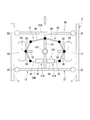
- the traveling carriage 6 includes a carriage body 11, a steering wheel 12, a guide device 13, and a steering mechanism 14.
- the cart body 11 supports the vehicle body 5 from below.
- the cart body 11 includes a cart frame 16, a shock absorber 17, and an axle 18.
- the shock absorber 17 is provided between the vehicle body 5 and the carriage frame 16.
- the shock absorber 17 prevents vibration due to unevenness on the road surface of the traveling road 4 from being transmitted to the vehicle body 5.
- the shock absorber 17 includes a spring member 19, for example.
- two spring members 19 are arranged at intervals in the vehicle width direction of the vehicle body 5.
- the spring member 19 may be an air spring, for example.
- the axle 18 is supported by the bogie frame 16.
- the axle 18 extends on both sides in the vehicle width direction from a gear box 20 disposed in the center in the vehicle width direction.
- the gear box 20 accommodates a mechanism such as a differential gear that transmits rotational power from a power source (not shown) such as a motor to the axle 18.
- a power source not shown
- the gear box 20 is fixed to the lower side of the carriage frame 16 so that the axle 18 is supported by the carriage frame 16 via the gear box 20, but the present invention is not limited thereto.
- the steering wheel 12 is a so-called wheel with a tire on which a rubber tire is mounted.
- the steering wheel 12 is connected to both ends of each axle 18 extending on both sides in the vehicle width direction, and is configured to be rotatable around the axle 18 together with the axle 18. Thereby, the vehicle 1 can travel on the travel path 4 of the track 2. Further, the steering wheel 12 is configured to be rotatable around a steering shaft O1 (for example, a king pin) disposed at both ends of the axle 18 in the vehicle width direction with respect to the carriage main body 11.
- the direction of the traveling direction of the vehicle 1 can be changed by turning the steering wheel 12 around the steering axis O1.
- the guide device 13 is arranged below the carriage main body 11 and is supported so as to be able to turn around a turning axis O2 extending in the vertical direction with respect to the carriage main body 11.
- the guide device 13 turns by receiving a reaction force from the guide rail 3.
- the guide device 13 includes a guide frame 21 and guide wheels 22.
- the guide frame 21 includes horizontal beams 23A and 23B and a vertical beam 24.
- the lateral beams 23A and 23B are formed so as to extend to both outer sides in the vehicle width direction from the steering wheel 12. Further, the cross beams 23A and 23B are respectively disposed in front and rear in the traveling direction of the steering wheel 12.
- the vertical beam 24 extends in the traveling direction of the steered wheel 12 and connects the pair of front and rear horizontal beams 23A and 23B at an intermediate portion in the vehicle width direction.
- the vertical beam 24 is attached to the carriage main body 11 so as to be capable of turning about the turning axis O2 at an intermediate portion in the extending direction.
- the guide wheels 22 are guided by guide rails 3 arranged on both sides of the track 2 in the vehicle width direction.
- the guide wheel 22 is attached to both ends of each of the horizontal beams 23A and 23B, and is configured to be rotatable about an axis O3 extending in the vertical direction.
- the guide wheel 22 rolls along the guide rail 3 by contacting the guide rail 3 when the vehicle 1 travels on the track 2.
- the width dimension of the guide device 13 along the extending direction of the cross beams 23 ⁇ / b> A and 23 ⁇ / b> B is set smaller than the dimension between the guide rails 3. Further, in the guide device 13, a part of the guide wheels 22 is pressed against the guide rail 3, thereby turning by receiving a reaction force from the guide rail 3 (see FIG. 5).
- the steering mechanism 14 applies a steering force to the steered wheels 12 using the reaction force received by the guide device 13 described above.
- the steering mechanism 14 connects the guide device 13 and the steering shaft O1 of the steering wheel 12 to each other, and when the guide device 13 turns, the steering wheel 12 moves around the steering axis O1 in the same direction as the turning direction of the guide device 13.
- a steering mechanism 14 is provided for each steering wheel 12.
- Each steering mechanism 14 includes a first connection arm 25 and a second connection arm 26. A first end in the longitudinal direction of the first connecting arm 25 is attached to the steering wheel 12 so as to be rotatable around the steering axis O1 (the steering direction of the steering wheel 12).
- the second connecting arm 26 connects the first connecting arm 25 and the vertical beam 24 of the guide frame 21.
- a first end in the longitudinal direction of the second connecting arm 26 is rotatably connected to a second end of the first connecting arm 25.
- a second end of the second connecting arm 26 is rotatably connected to the vertical beam 24 of the guide frame 21.
- a connection portion of the vertical beam 24 with the second connection arm 26 is located between the turning axis O2 and an end portion of the vertical beam 24 (connection portion between the horizontal beams 23A and 23B).
- the connecting portion of the first and second connecting arms 25 and 26 is located on the front side in the traveling direction of the vehicle 1 (traveling carriage 6) with respect to the steering shaft O1, and the second connecting arm in the vertical beam 24.
- connection part with 26 is located in the front side of the running direction of vehicle 1 (running carriage 6) rather than turning axis O2, it is not restricted to this.
- the connecting portion of the first and second connecting arms 25 and 26 is located on the rear side in the traveling direction of the vehicle 1 (traveling carriage 6) with respect to the steering shaft O1, and the second connecting arm 26 in the vertical beam 24 and May be located behind the turning axis O2 in the traveling direction of the vehicle 1 (traveling carriage 6).
- the steering mechanism 14 configured as described above, when the guide device 13 receives the reaction force from the guide rail 3 and turns around the turning axis O2, the second connecting arm 26 is displaced, and further, the first connecting arm 25 is moved to the steering shaft.
- the steered wheel 12 is steered in the same direction as the turning direction of the guide device 13 (see FIG. 5). That is, the steering mechanism 14 steers the steering wheel 12 in the same direction as the turning direction of the guide device 13 by applying a steering force to the steering wheel 12 using the reaction force received by the guide device 13.
- the traveling carriage 6 includes an assist mechanism 15 that applies an auxiliary steering force that assists the steering force by the steering mechanism 14 to the steering wheel 12.
- the assist mechanism 15 includes an actuator 31, a detection unit 32, and a control unit 33.
- the actuator 31 generates an auxiliary steering force.
- the actuator 31 of this embodiment is, for example, an air cylinder, a hydraulic cylinder, or an electric cylinder, and includes a cylinder body 34 and a piston rod 35.
- the cylinder body 34 is attached to the carriage body 11.
- the piston rod 35 is attached to the cylinder body 34 so as to extend and contract.
- the expansion / contraction direction of the piston rod 35 is set in the vehicle width direction.
- a first end of the assist arm 36 is rotatably connected to the tip of the piston rod 35 of the actuator 31.
- a second end of the assist arm 36 is attached to the steering wheel 12 so as to be rotatable around the steering axis O1.
- the piston rod 35 extends and contracts with respect to the cylinder body 34.
- the force for expanding and contracting the piston rod 35 is transmitted to the steering wheel 12 via the assist arm 36 and is applied to the steering wheel 12 as an auxiliary steering force.
- the force for expanding and contracting the piston rod 35 (auxiliary steering force) and the displacement of the piston rod 35 are controlled based on a control signal from the control unit 33 described later.
- the actuator 31 of this embodiment is connected to only one of the steering wheels 12 via the assist arm 36.
- the auxiliary steering force of the actuator 31 is transmitted to the other steering wheel 14 via the steering mechanism 14 coupled to one steering wheel 12, the guide frame 21 (vertical beam 24), and the steering mechanism 14 coupled to the other steering wheel 12. It is also given to the steering wheel 12.
- the detection unit 32 detects the state of the guide device 13.
- the detection unit 32 of the present embodiment detects the turning angle of the guide device 13 as the state of the guide device 13.
- the turning direction of the guide device 13 corresponds to the steering direction of the steered wheels 12 connected to the guide device 13 by the steering mechanism 14. Therefore, the detection unit 32 can detect the steering angle of the steered wheels 12 by detecting the turning angle of the guide device 13.
- the turning angle of the guide device 13 and the steering angle of the steered wheel 12 detected by the detection unit 32 are angles based on the direction of the steered wheel 12 in the straight traveling state (and the corresponding turning position of the guide device 13). It is.
- the detection unit 32 of this embodiment includes a detection link 37 and a detection sensor 38.
- the detection link 37 is rotatably attached to the cart body 11.
- the first end of the detection link 37 is connected to the cross beam 23 ⁇ / b> A of the guide device 13. Thereby, the detection link 37 rotates corresponding to the turning of the guide device 13.
- the second end of the detection link 37 is arranged so as to approach or separate from the detection sensor 38 fixed to the carriage body 11 according to the rotation of the detection link 37.
- the detection sensors 38 are arranged on both sides in the moving direction of the second end of the detection link 37, but may be arranged on only one side, for example.
- the detection sensor 38 detects the movement of the detection link 37, and an arbitrary type such as a load detection type, a contact type, a displacement detection type, or a laser detection type can be used.
- the detection result of the detection sensor 38 is output to the control unit 33 as a detection signal.
- the control unit 33 controls the operation of the actuator 31 based on the detection result of the detection unit 32 (detection sensor 38).
- the control unit 33 of the present embodiment will be described in detail.
- the control unit 33 Based on the turning angle of the guide device 13 (steering angle of the steering wheel 12) detected by the detection unit 32, the control unit 33 attempts to return the self-aligning torque (steering wheel 12 to the straight traveling state) of the steering wheel 12. (Rotational force) to be calculated as a reaction force received by the guide device 13.
- the width dimension and material of the steered wheels 12, the travel speed, the vehicle load applied to the steered wheels 12, and the like can be taken into consideration.
- the control unit 33 sets an auxiliary steering force to be applied to the steered wheels 12 based on the calculated reaction force.
- the auxiliary steering force is smaller than the reaction force received by the guide device 13, and is set to 50% of the reaction force, for example.
- the control unit 33 outputs a control signal including the set auxiliary steering force to the actuator 31.
- the actuator 31 generates an auxiliary steering force.
- control unit 33 prevents the steering wheel 12 from being excessively steered by the displacement of the piston rod 35 relative to the cylinder body 34 (displacement of the actuator 31) based on the turning angle of the guide device 13 detected by the detection unit 32. Then, the displacement of the actuator 31 is calculated. For example, the displacement of the actuator 31 is calculated so that the assist arm 36 rotates in accordance with the steering angle of the steered wheel 12 and the rotation of the assist arm 36 is not hindered by the piston rod 35. Thereafter, the control unit 33 outputs a control signal including the calculated displacement of the actuator 31 to the actuator 31.
- control unit 33 outputs a control signal including an auxiliary steering force to the actuator 31 when the calculated reaction force is equal to or less than a predetermined value and the turning angle of the guide device 13 or the steering angle of the steering wheel 12 is equal to or less than the predetermined angle. Is not output. That is, when the steering angle of the steered wheel 12 is equal to or smaller than the predetermined angle, the actuator 31 does not generate an auxiliary steering force.
- a steering force using the reaction force F described above is applied to the steering wheel 12 by the steering mechanism 14, and the steering wheel 12 has the same turning direction as the guide device 13 around the steering axis O ⁇ b> 1.
- the steered wheels 12 can be directed in the traveling direction of the vehicle 1 along the curved portion of the track 2.
- the vehicle 1 travels along the curved portion of the track 2.
- the assist steering force by the assist mechanism 15 is also applied to the steered wheel 12. This will be specifically described below.
- the detection sensor 38 of the detection unit 32 detects the movement of the detection link 37 connected to the guide device 13.
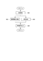
- the control unit 33 receives a signal from the detection sensor 38 and detects the turning angle of the guide device 13 (the state of the guide device 13) (step S01).
- the control unit 33 calculates a reaction force F received by the guide device 13 based on the turning angle of the guide device 13, and further adds an auxiliary steering force to be applied to the steered wheels 12 based on the calculated reaction force F.
- Set step S02
- the control unit 33 calculates the displacement of the actuator 31 based on the turning angle of the guide device 13 (step S03).
- the displacement of the actuator 31 is calculated so that the steering wheel 12 is not excessively steered by the displacement.
- the control unit 33 outputs a control signal including the auxiliary steering force and the displacement of the actuator 31 set in Step S02 and Step S03 to the actuator 31 (Step S04).
- the processes in steps S01 to S04 are repeatedly performed while the vehicle is traveling on the traveling path 4 of the track 2.
- the actuator 31 generates an auxiliary steering force based on the control signal output from the control unit 33.
- This auxiliary steering force is applied to the steering wheel 12 via the assist arm 36.
- the displacement of the piston rod 35 with respect to the cylinder body 34 is set by the control signal output from the control unit 33, so that the steering wheel 12 can be prevented from being steered by the operation of the actuator 31.
- the traveling carriage 6 of the present embodiment and the vehicle 1 including the same when the steering wheel 12 is steered by the steering mechanism 14, the auxiliary steering force by the assist mechanism 15 is also applied to the steering wheel 12. The For this reason, even if the steered wheel 12 is wide, the steered wheel 12 can be steered while suppressing the reaction force that the guide device 13 receives from the guide rail 3. Therefore, it is possible to provide the vehicle 1 that can cope with an increase in load resistance and a high-speed track system.
- the control unit 33 controls the operation of the actuator 31 based on the turning angle of the guide device 13 (the state of the guide device 13) detected by the detection unit 32. Therefore, the auxiliary steering force can be applied to the steered wheels 12 with high accuracy. Therefore, it is possible to prevent the steering angle of the steered wheels 12 steered by the steering mechanism 14 from changing due to the application of the auxiliary steering force.
- the cylinder body 34 of the actuator 31 is attached to the carriage body 11, when the auxiliary steering force generated by the actuator 31 is transmitted to the steering wheel 12, the reaction force of the auxiliary steering force can be received by the carriage body 11. it can. For this reason, the auxiliary steering force can be efficiently applied to the steered wheels 12. Further, according to the present embodiment, even when the guide device 13 receives a minute reaction force from the guide rail 3 when the vehicle 1 travels on the straight portion of the track 2, the steering angle of the steered wheels 12 associated therewith is predetermined. If the angle is equal to or smaller than the angle, the auxiliary steering force is not applied to the steered wheels 12.
- the steering wheel 12 is quickly brought straight ahead by the self-aligning torque. It becomes possible to return. Therefore, the vehicle 1 can travel on the straight portion of the track 2 in a stable state.
- the assist mechanism 15A included in the traveling vehicle 6A of the track type vehicle (vehicle) of the present embodiment includes the same actuator 31A as in the first embodiment.
- an actuator 31A is provided for each steered wheel 12.
- Each actuator 31A includes the same cylinder body 34 and piston rod 35 as in the first embodiment.
- the piston rod 35 of each actuator 31A is connected to each steered wheel 12 via each assist arm 36 as in the case of the first embodiment.
- the operation of each actuator 31A is controlled based on a control signal from the control unit 33 (see FIG. 3) similar to the first embodiment.
- the traveling cart 6A and the track type vehicle of the present embodiment have the same effects as the first embodiment. Further, according to the traveling carriage 6A and the track-type vehicle of the present embodiment, in each actuator 31A, compared to the configuration of the first embodiment in which the auxiliary steering force of the single actuator 31 is applied to the pair of steering wheels 12. The magnitude of the auxiliary steering force to be generated can be reduced. That is, the actuator 31A having a smaller output can be provided as compared with the case of the first embodiment. Therefore, the assist mechanism 15A can be configured by the inexpensive actuator 31A, and the manufacturing cost of the traveling carriage 6A can be reduced.
- the detection unit 32 of the assist mechanisms 15 and 15 ⁇ / b> A detects the turning angle of the guide device 13 as the state of the guide device 13.
- the reaction force received by the guide device 13 may be detected.
- the force by which the second end of the detection link 37 that rotates with the turning of the guide device 13 is pressed against the detection sensor 38 may be detected as a reaction force.
- the control unit 33 may set the auxiliary steering force based on the reaction force that is the detection result.
- the control part 33 should just calculate the displacement of the actuator 31 based on the reaction force which is a detection result.
- the present invention is not limited to the traveling carriage 6 that travels while being guided by the side guide type guide rails 3 provided at both ends in the width direction of the track 2 as in the above embodiment, for example, the center portion in the width direction of the track.
- the present invention is also applicable to a traveling carriage that is guided by a center guide type guide rail provided in the vehicle.
- this traveling carriage it is possible to steer a wide steered wheel while suppressing the reaction force received by the guide device from the guide rail.
Landscapes
- Engineering & Computer Science (AREA)
- Mechanical Engineering (AREA)
- Transportation (AREA)
- Platform Screen Doors And Railroad Systems (AREA)
Abstract
この走行台車(6)は、操舵輪(12)と、操舵輪(12)を支持する台車本体(11)と、台車本体(11)に回動可能に支持されて、ガイドレール(3)からの反力を受けて旋回する案内装置(13)と、案内装置(13)が受けた反力を利用して操舵輪(12)に操舵力を付与する操舵機構(14)と、操舵機構(14)による操舵力を補助する補助操舵力を操舵輪(12)に付与するアシスト機構(15)と、を備える。
Description
本発明は、走行台車及び軌道式車両に関する。本願は、2013年11月28日に、日本に出願された特願2013-245814号に基づき優先権を主張し、その内容をここに援用する。
バスや鉄道以外の新たな交通手段として、ゴムタイヤからなる走行輪によって軌道上を走行する軌道系交通システムが知られている。この種の軌道系交通システムは、一般に、「新交通システム」や「APM(Automated People Mover)」等と呼ばれている。軌道系交通システムでは、車両の両側部などに配された案内輪が、軌道に沿って設けられたガイドレールによって案内される。
上述した軌道系交通システムの車両において、走行輪や案内輪は、車両の下部に配された走行台車に設けられている。走行台車は、車両が曲線部分を通過する際に、案内輪がガイドレールに押し付けられる力(反力)を利用して、走行輪(操舵輪)を操舵する機構を備えている(例えば特許文献1参照)。特許文献1には、案内輪を有し、車両に対して旋回可能に取り付けられた案内装置と、案内装置の旋回に応じて操舵輪を操舵する操舵機構(タイロッド、タイロッドアーム)と、を備えた走行台車が開示されている。
近年では、車両の耐荷重の増加や、軌道系交通システムの高速化などが求められており、これに伴って、幅広の走行輪を使用することが考えられている。
しかしながら、操舵輪の幅寸法が大きくなると、操舵輪と軌道との摩擦力、キングピンオフセット量、セルフアライニングトルク等が大きくなるため、操舵輪の操舵に要する力が大きくなる。すなわち、操舵輪を操舵する際に案内装置がガイドレールから受ける反力が大きくなる。
その一方で、案内装置やガイドレールの強度や耐久性には制約があるため、操舵輪を操舵する際に案内装置がガイドレールから受ける反力の大きさにも制約がある。
しかしながら、操舵輪の幅寸法が大きくなると、操舵輪と軌道との摩擦力、キングピンオフセット量、セルフアライニングトルク等が大きくなるため、操舵輪の操舵に要する力が大きくなる。すなわち、操舵輪を操舵する際に案内装置がガイドレールから受ける反力が大きくなる。
その一方で、案内装置やガイドレールの強度や耐久性には制約があるため、操舵輪を操舵する際に案内装置がガイドレールから受ける反力の大きさにも制約がある。
本発明は、案内装置が受ける反力を小さく抑えながら、幅広の操舵輪を操舵することが可能な走行台車及び軌道式車両を提供する。
本発明の第一の態様によれば、走行台車は、軌道に沿って設けられたガイドレールに案内されて走行する走行台車であって、操舵輪と、前記操舵輪を支持する台車本体と、前記台車本体に回動可能に支持されて、前記ガイドレールからの反力を受けて旋回する案内装置と、前記案内装置が受けた反力を利用して前記操舵輪に操舵力を付与する操舵機構と、前記操舵機構による操舵力を補助する補助操舵力を前記操舵輪に付与するアシスト機構と、を備える。
上記構成の走行台車が軌道の曲線部分を走行する際には、案内装置がガイドレールに押し付けられることで、案内装置がガイドレールからの反力を受けて旋回する。また、操舵機構によって前述の反力を利用した操舵力が操舵輪に付与されることで、操舵輪が操舵され、操舵輪を軌道の曲線部分に沿う走行台車の進行方向に向けることができる。
そして、上記構成の走行台車では、操舵機構により操舵輪が操舵される際に、アシスト機構による補助操舵力も操舵輪に付与されるため、案内装置がガイドレールから受ける反力を小さく抑えながら、操舵輪を操舵することが可能となる。
そして、上記構成の走行台車では、操舵機構により操舵輪が操舵される際に、アシスト機構による補助操舵力も操舵輪に付与されるため、案内装置がガイドレールから受ける反力を小さく抑えながら、操舵輪を操舵することが可能となる。
本発明の第二の態様によれば、前記走行台車においては、前記アシスト機構が、前記補助操舵力を発生するアクチュエータと、前記案内装置の状態を検出する検出部と、前記検出部の検出結果に応じて前記アクチュエータの動作を制御する制御部と、を備えてもよい。
上記走行台車において、検出部が検出する案内装置の状態とは、例えば台車本体に対する案内装置の旋回角度や、案内装置がガイドレールから受ける反力である。
上記構成の走行台車によれば、制御部が検出部において検出された案内装置の状態に基づいてアクチュエータの動作を制御するため、補助操舵力を高い精度で操舵輪に付与することが可能となる。したがって、操舵機構によって操舵された操舵輪の操舵角度が、補助操舵力の付与によって変化することを防止できる。
上記構成の走行台車によれば、制御部が検出部において検出された案内装置の状態に基づいてアクチュエータの動作を制御するため、補助操舵力を高い精度で操舵輪に付与することが可能となる。したがって、操舵機構によって操舵された操舵輪の操舵角度が、補助操舵力の付与によって変化することを防止できる。
本発明の第三の態様によれば、前記走行台車においては、前記アクチュエータが、前記台車本体に取り付けられてもよい。
上記構成の走行台車によれば、アクチュエータで発生した補助操舵力を操舵輪に伝達する際、補助操舵力の反力を台車本体で受けることができるため、補助操舵力を効率よく操舵輪に付与することができる。
本発明の第四の態様によれば、前記走行台車においては、前記操舵輪が、車幅方向に間隔をあけて一対設けられ、前記アクチュエータが、一対の操舵輪に対して個別に設けられてもよい。
上記構成の走行台車によれば、単一のアクチュエータの補助動作力を一対の操舵輪に付与する場合と比較して、各アクチュエータにおいて発生させる補助操舵力の大きさを小さくできる。すなわち、出力の小さいアクチュエータを設けることができる。したがって、安価なアクチュエータによってアシスト機構を構成し、走行台車の製造コスト削減を図ることができる。
本発明の第五の態様によれば、軌道式車両は、前記走行台車と、前記走行台車に支持される車体と、を備える。
上述した走行台車によれば、案内装置がガイドレールから受ける反力を小さく抑えながら、幅広の操舵輪を操舵することが可能となる。
〔第一実施形態〕
以下、図1~6を参照して本発明の第一実施形態について説明する。
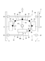
図1,2に示すように、本実施形態における軌道式車両1(以下、単に車両1と称す)は、軌道2の幅方向の両側部に設けられた、いわゆるサイドガイド型のガイドレール3によって案内されて軌道2の走行路4上を走行する。
車両1は、車体5と、走行台車6とを備える。車体5は、走行方向の前後に長い中空の略直方体の形状を有する。この車体5の内部には、乗客を収容可能な空間が形成されている。
以下、図1~6を参照して本発明の第一実施形態について説明する。
図1,2に示すように、本実施形態における軌道式車両1(以下、単に車両1と称す)は、軌道2の幅方向の両側部に設けられた、いわゆるサイドガイド型のガイドレール3によって案内されて軌道2の走行路4上を走行する。
車両1は、車体5と、走行台車6とを備える。車体5は、走行方向の前後に長い中空の略直方体の形状を有する。この車体5の内部には、乗客を収容可能な空間が形成されている。
走行台車6は、車体5を下方から支持し、軌道2上を走行する。走行台車6は、車体5の前部及び後部の下方に配置されている。各走行台車6は、車体5の前部に配置されるか、後部に配置されるかの違いだけであるため、以下の説明においては、前部に配置される走行台車6についてのみ説明する。
走行台車6は、台車本体11と、操舵輪12と、案内装置13と、操舵機構14と、を備える。台車本体11は、車体5を下方から支持する。台車本体11は、台車枠16と、緩衝装置17と、車軸18と、を備える。
緩衝装置17は、車体5と台車枠16との間に設けられている。緩衝装置17は、走行路4の路面上の凹凸などによる振動が車体5に伝わることを防止する。緩衝装置17は、例えばばね部材19を備える。ばね部材19は、例えば車体5の車幅方向に互いに間隔をあけて二つ配されている。ばね部材19は、例えば空気ばねであってもよい。
緩衝装置17は、車体5と台車枠16との間に設けられている。緩衝装置17は、走行路4の路面上の凹凸などによる振動が車体5に伝わることを防止する。緩衝装置17は、例えばばね部材19を備える。ばね部材19は、例えば車体5の車幅方向に互いに間隔をあけて二つ配されている。ばね部材19は、例えば空気ばねであってもよい。
車軸18は、台車枠16に支持されている。車軸18は、車幅方向の中央部に配されたギヤボックス20から車幅方向両側に延びている。ギヤボックス20には、モータ等の動力源(図示せず)からの回転動力を車軸18に伝達するディファレンシャルギヤなどの機構が収容されている。図示例では、ギヤボックス20が台車枠16の下側に固定されることで、車軸18がギヤボックス20を介して台車枠16に支持されているが、これに限ることはない。
操舵輪12は、ゴムタイヤが装着された所謂タイヤ付ホイールである。操舵輪12は、車幅方向の両側に延びる各車軸18の両端に接続され、車軸18と共に車軸18を中心に回転可能に構成されている。これにより、車両1が軌道2の走行路4上を走行することができる。また、操舵輪12は、台車本体11に対して車軸18の車幅方向の両側の端部に配された操舵軸O1(例えばキングピン)回りに回動可能に構成されている。操舵輪12が操舵軸O1回りに回動することで、車両1の進行方向の向きを変えることができる。
案内装置13は、台車本体11の下方に配され、台車本体11に対して上下方向に延びる旋回軸O2回りに旋回可能に支持されている。案内装置13は、ガイドレール3からの反力を受けて旋回する。案内装置13は、案内枠21と、案内輪22と、を備える。
案内枠21は、横梁23A,23Bと、縦梁24と、を備える。横梁23A,23Bは、操舵輪12よりも車幅方向の両外側まで延びて形成されている。また、横梁23A,23Bは、操舵輪12の走行方向の前方および後方にそれぞれ配置されている。縦梁24は、操舵輪12の走行方向に延びており、前後一対の横梁23A,23B同士を車幅方向の中間部分において接続している。縦梁24は、その延在方向の中間部分において台車本体11に対して旋回軸O2回りに旋回可能に取り付けられている。
案内枠21は、横梁23A,23Bと、縦梁24と、を備える。横梁23A,23Bは、操舵輪12よりも車幅方向の両外側まで延びて形成されている。また、横梁23A,23Bは、操舵輪12の走行方向の前方および後方にそれぞれ配置されている。縦梁24は、操舵輪12の走行方向に延びており、前後一対の横梁23A,23B同士を車幅方向の中間部分において接続している。縦梁24は、その延在方向の中間部分において台車本体11に対して旋回軸O2回りに旋回可能に取り付けられている。
案内輪22は、軌道2の車幅方向の両側に配置されたガイドレール3によって案内される。案内輪22は、各横梁23A,23Bの両端部に取り付けられ、上下方向に延びる軸線O3回りに回転自在に構成されている。案内輪22は、車両1が軌道2上を走行する際に、ガイドレール3に当接することでガイドレール3に沿って転動する。
この案内装置13において、横梁23A,23Bの延在方向に沿う案内装置13の幅寸法は、ガイドレール3間の寸法よりも小さく設定されている。また、案内装置13では、一部の案内輪22がガイドレール3に押し付けられることで、ガイドレール3からの反力を受けて旋回する(図5参照)。
この案内装置13において、横梁23A,23Bの延在方向に沿う案内装置13の幅寸法は、ガイドレール3間の寸法よりも小さく設定されている。また、案内装置13では、一部の案内輪22がガイドレール3に押し付けられることで、ガイドレール3からの反力を受けて旋回する(図5参照)。
操舵機構14は、上記した案内装置13が受けた反力を利用して操舵輪12に操舵力を付与する。操舵機構14は、案内装置13及び操舵輪12の操舵軸O1を相互に連結して、案内装置13が旋回した際に、操舵輪12を操舵軸O1回りに案内装置13の旋回方向と同じ方向に回動させる。操舵機構14は、操舵輪12毎に設けられている。各操舵機構14は、第一連結アーム25と、第二連結アーム26と、を備える。
第一連結アーム25の長手方向の第一端は、操舵輪12と共に操舵軸O1回り(操舵輪12の操舵方向)に回動可能に取り付けられている。
第一連結アーム25の長手方向の第一端は、操舵輪12と共に操舵軸O1回り(操舵輪12の操舵方向)に回動可能に取り付けられている。
第二連結アーム26は、第一連結アーム25と、案内枠21の縦梁24とを連結する。
第二連結アーム26の長手方向の第一端は、第一連結アーム25の第二端に回転自在に連結されている。第二連結アーム26の第二端は、案内枠21の縦梁24に回転自在に連結されている。縦梁24における第二連結アーム26との連結部分は、旋回軸O2と、縦梁24の端部(横梁23A,23Bとの接続部分)との間に位置している。図示例では、第一、第二連結アーム25,26の連結部分が操舵軸O1よりも車両1(走行台車6)の走行方向の前方側に位置し、かつ、縦梁24における第二連結アーム26との連結部分が旋回軸O2よりも車両1(走行台車6)の走行方向の前方側に位置しているが、これに限らない。例えば、第一、第二連結アーム25,26の連結部分が操舵軸O1よりも車両1(走行台車6)の走行方向の後方側に位置し、かつ、縦梁24における第二連結アーム26との連結部分が旋回軸O2よりも車両1(走行台車6)の走行方向の後方側に位置してもよい。
第二連結アーム26の長手方向の第一端は、第一連結アーム25の第二端に回転自在に連結されている。第二連結アーム26の第二端は、案内枠21の縦梁24に回転自在に連結されている。縦梁24における第二連結アーム26との連結部分は、旋回軸O2と、縦梁24の端部(横梁23A,23Bとの接続部分)との間に位置している。図示例では、第一、第二連結アーム25,26の連結部分が操舵軸O1よりも車両1(走行台車6)の走行方向の前方側に位置し、かつ、縦梁24における第二連結アーム26との連結部分が旋回軸O2よりも車両1(走行台車6)の走行方向の前方側に位置しているが、これに限らない。例えば、第一、第二連結アーム25,26の連結部分が操舵軸O1よりも車両1(走行台車6)の走行方向の後方側に位置し、かつ、縦梁24における第二連結アーム26との連結部分が旋回軸O2よりも車両1(走行台車6)の走行方向の後方側に位置してもよい。
上記構成の操舵機構14では、案内装置13がガイドレール3からの反力を受けて旋回軸O2回りに旋回した際に、第二連結アーム26が変位し、さらに第一連結アーム25が操舵軸O1回りに回動することで、操舵輪12が案内装置13の旋回方向と同じ方向に操舵される(図5参照)。すなわち、操舵機構14は、案内装置13が受ける反力を利用して操舵輪12に操舵力を付与することで、操舵輪12を案内装置13の旋回方向と同じ方向に操舵する。
さらに、走行台車6は、図1~3に示すように、上記した操舵機構14による操舵力を補助する補助操舵力を操舵輪12に付与するアシスト機構15を備える。アシスト機構15は、アクチュエータ31と、検出部32と、制御部33と、を備える。
アクチュエータ31は、補助操舵力を発生する。本実施形態のアクチュエータ31は、例えばエアシリンダ、油圧シリンダ、電動シリンダであり、シリンダ本体34及びピストンロッド35を備える。シリンダ本体34は、台車本体11に取り付けられている。ピストンロッド35は、シリンダ本体34に伸縮可能に取り付けられている。ピストンロッド35の伸縮方向は車幅方向に設定されている。アクチュエータ31のピストンロッド35の先端には、アシストアーム36の第一端が回転可能に連結されている。アシストアーム36の第二端は、操舵輪12と共に操舵軸O1回りに回動可能に取り付けられている。
アクチュエータ31は、補助操舵力を発生する。本実施形態のアクチュエータ31は、例えばエアシリンダ、油圧シリンダ、電動シリンダであり、シリンダ本体34及びピストンロッド35を備える。シリンダ本体34は、台車本体11に取り付けられている。ピストンロッド35は、シリンダ本体34に伸縮可能に取り付けられている。ピストンロッド35の伸縮方向は車幅方向に設定されている。アクチュエータ31のピストンロッド35の先端には、アシストアーム36の第一端が回転可能に連結されている。アシストアーム36の第二端は、操舵輪12と共に操舵軸O1回りに回動可能に取り付けられている。
このアクチュエータ31では、ピストンロッド35がシリンダ本体34に対して伸縮する。ピストンロッド35を伸縮させる力は、アシストアーム36を介して操舵輪12に伝えられ、補助操舵力として操舵輪12に付与される。ピストンロッド35を伸縮させる力(補助操舵力)やピストンロッド35の変位は、後述する制御部33からの制御信号に基づいて制御される。
本実施形態のアクチュエータ31は、アシストアーム36を介して一方の操舵輪12のみに連結されている。アクチュエータ31の補助操舵力は、一方の操舵輪12に連結された操舵機構14、案内枠21(縦梁24)、及び、他方の操舵輪12に連結された操舵機構14を介して、他方の操舵輪12にも付与される。
検出部32は、案内装置13の状態を検出する。本実施形態の検出部32は、案内装置13の状態として、案内装置13の旋回角度を検出する。ここで、案内装置13の旋回方向は、操舵機構14により案内装置13と連結された操舵輪12の操舵方向に対応する。
このため、検出部32は、案内装置13の旋回角度を検出することで、操舵輪12の操舵角度を検出することができる。検出部32が検出する案内装置13の旋回角度、操舵輪12の操舵角度は、直進状態とされた操舵輪12の向き(また、これに対応する案内装置13の旋回位置)を基準とした角度である。
このため、検出部32は、案内装置13の旋回角度を検出することで、操舵輪12の操舵角度を検出することができる。検出部32が検出する案内装置13の旋回角度、操舵輪12の操舵角度は、直進状態とされた操舵輪12の向き(また、これに対応する案内装置13の旋回位置)を基準とした角度である。
本実施形態の検出部32は、検出用リンク37及び検出センサ38を備える。
検出用リンク37は、台車本体11に回転自在に取り付けられている。検出用リンク37の第一端は、案内装置13の横梁23Aに連結されている。これにより、検出用リンク37は案内装置13の旋回に対応して回転する。検出用リンク37の第二端は、検出用リンク37の回転に応じて、台車本体11に固定された検出センサ38に対して近づいたり離れたりするように配されている。図示例では、検出センサ38が検出用リンク37の第二端の移動方向の両側に配されているが、例えば片側だけに配されてもよい。
検出センサ38は、検出用リンク37の動きを検出するものであり、荷重検知式、接触式、変位検知式、レーザー感知式等、任意の方式のものを使用することが可能である。検出センサ38の検出結果は検出信号として制御部33に出力される。
検出用リンク37は、台車本体11に回転自在に取り付けられている。検出用リンク37の第一端は、案内装置13の横梁23Aに連結されている。これにより、検出用リンク37は案内装置13の旋回に対応して回転する。検出用リンク37の第二端は、検出用リンク37の回転に応じて、台車本体11に固定された検出センサ38に対して近づいたり離れたりするように配されている。図示例では、検出センサ38が検出用リンク37の第二端の移動方向の両側に配されているが、例えば片側だけに配されてもよい。
検出センサ38は、検出用リンク37の動きを検出するものであり、荷重検知式、接触式、変位検知式、レーザー感知式等、任意の方式のものを使用することが可能である。検出センサ38の検出結果は検出信号として制御部33に出力される。
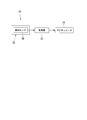
制御部33は、上記した検出部32(検出センサ38)の検出結果に基づいてアクチュエータ31の動作を制御する。以下、本実施形態の制御部33について詳細に説明する。
制御部33は、検出部32によって検出された案内装置13の旋回角度(操舵輪12の操舵角度)に基づいて、操舵輪12のセルフアライニングトルク(操舵輪12を直進状態に復帰させようとする回転力)を、案内装置13が受ける反力として算出する。この算出に際しては、操舵輪12の幅寸法や材質、走行速度、操舵輪12にかかる車両の荷重なども考慮することができる。
そして、制御部33は、算出された反力に基づいて、操舵輪12に付与する補助操舵力を設定する。補助操舵力は、案内装置13が受ける反力よりも小さく、例えば反力の50%に設定される。その後、制御部33は、設定された補助操舵力を含む制御信号をアクチュエータ31に出力する。これにより、アクチュエータ31が補助操舵力を発生する。
制御部33は、検出部32によって検出された案内装置13の旋回角度(操舵輪12の操舵角度)に基づいて、操舵輪12のセルフアライニングトルク(操舵輪12を直進状態に復帰させようとする回転力)を、案内装置13が受ける反力として算出する。この算出に際しては、操舵輪12の幅寸法や材質、走行速度、操舵輪12にかかる車両の荷重なども考慮することができる。
そして、制御部33は、算出された反力に基づいて、操舵輪12に付与する補助操舵力を設定する。補助操舵力は、案内装置13が受ける反力よりも小さく、例えば反力の50%に設定される。その後、制御部33は、設定された補助操舵力を含む制御信号をアクチュエータ31に出力する。これにより、アクチュエータ31が補助操舵力を発生する。
また、制御部33は、検出部32によって検出された案内装置13の旋回角度に基づいて、シリンダ本体34に対するピストンロッド35の変位(アクチュエータ31の変位)によって操舵輪12が過剰に操舵されないように、アクチュエータ31の変位を算出する。例えば、アクチュエータ31の変位は、操舵輪12の操舵角度にあわせてアシストアーム36が回動し、アシストアーム36の回動がピストンロッド35によって阻害されないように、算出される。その後、制御部33は、算出されたアクチュエータ31の変位を含む制御信号をアクチュエータ31に出力する。
また、制御部33は、算出された反力が所定値以下であり、案内装置13の旋回角度や操舵輪12の操舵角度が所定角度以下の場合に、補助操舵力を含む制御信号をアクチュエータ31に出力しない。すなわち、操舵輪12の操舵角度が所定角度以下の場合、アクチュエータ31は補助操舵力を発生しない。
次に、上記のように構成される本実施形態の車両1の動作について説明する。
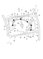
車両1が、図4,5に示すように、軌道2の曲線部分を走行する際には、案内装置13の案内輪22が、曲線部分の外軌側に配されるガイドレール3から、主に前方の外軌側の案内輪22が車幅方向外側からの反力Fを受ける。この反力Fに基づいて、案内装置13は、案内装置13の前方側(横梁23A側)が内軌側のガイドレール3に近づくように旋回軸O2回りに旋回する。また、案内装置13の旋回に伴い、操舵機構14により前述の反力Fを利用した操舵力が操舵輪12に付与されて、操舵輪12が操舵軸O1回りに案内装置13の旋回方向と同じ方向に操舵される。すなわち、操舵輪12を軌道2の曲線部分に沿う車両1の進行方向に向けることができる。これにより、車両1が軌道2の曲線部分に沿って走行する。
車両1が、図4,5に示すように、軌道2の曲線部分を走行する際には、案内装置13の案内輪22が、曲線部分の外軌側に配されるガイドレール3から、主に前方の外軌側の案内輪22が車幅方向外側からの反力Fを受ける。この反力Fに基づいて、案内装置13は、案内装置13の前方側(横梁23A側)が内軌側のガイドレール3に近づくように旋回軸O2回りに旋回する。また、案内装置13の旋回に伴い、操舵機構14により前述の反力Fを利用した操舵力が操舵輪12に付与されて、操舵輪12が操舵軸O1回りに案内装置13の旋回方向と同じ方向に操舵される。すなわち、操舵輪12を軌道2の曲線部分に沿う車両1の進行方向に向けることができる。これにより、車両1が軌道2の曲線部分に沿って走行する。
また、軌道2の曲線部分において操舵輪12が操舵される際には、アシスト機構15による補助操舵力も操舵輪12に付与される。以下、具体的に説明する。
案内装置13がガイドレール3からの反力Fを受けて旋回した際には、検出部32の検出センサ38が案内装置13に連結された検出用リンク37の動きを検出する。この際、制御部33は、図6に示すように、検出センサ38からの信号を受信して、案内装置13の旋回角度(案内装置13の状態)を検出する(ステップS01)。次いで、制御部33は、案内装置13の旋回角度に基づいて案内装置13が受けた反力Fを算出し、さらに、算出された反力Fに基づいて操舵輪12に付与する補助操舵力を設定する(ステップS02)。また、制御部33は、案内装置13の旋回角度に基づいて、アクチュエータ31の変位を算出する(ステップS03)。アクチュエータ31の変位は、前記変位によって操舵輪12が過剰に操舵されないように算出される。その後、制御部33は、ステップS02及びステップS03において設定された補助操舵力及びアクチュエータ31の変位を含む制御信号をアクチュエータ31に出力する(ステップS04)。
上記ステップS01~S04の各処理は、車両が軌道2の走行路4上を走行している状態で繰り返し行われる。
案内装置13がガイドレール3からの反力Fを受けて旋回した際には、検出部32の検出センサ38が案内装置13に連結された検出用リンク37の動きを検出する。この際、制御部33は、図6に示すように、検出センサ38からの信号を受信して、案内装置13の旋回角度(案内装置13の状態)を検出する(ステップS01)。次いで、制御部33は、案内装置13の旋回角度に基づいて案内装置13が受けた反力Fを算出し、さらに、算出された反力Fに基づいて操舵輪12に付与する補助操舵力を設定する(ステップS02)。また、制御部33は、案内装置13の旋回角度に基づいて、アクチュエータ31の変位を算出する(ステップS03)。アクチュエータ31の変位は、前記変位によって操舵輪12が過剰に操舵されないように算出される。その後、制御部33は、ステップS02及びステップS03において設定された補助操舵力及びアクチュエータ31の変位を含む制御信号をアクチュエータ31に出力する(ステップS04)。
上記ステップS01~S04の各処理は、車両が軌道2の走行路4上を走行している状態で繰り返し行われる。
図5に示すように、アクチュエータ31は、制御部33から出力された制御信号に基づいて補助操舵力を発生する。この補助操舵力は、アシストアーム36を介して操舵輪12に付与される。また、アクチュエータ31では、制御部33から出力された制御信号によって、シリンダ本体34に対するピストンロッド35の変位が設定されるため、操舵輪12がアクチュエータ31の動作によって操舵されることを防止できる。
以上説明したように、本実施形態の走行台車6及びこれを備える車両1によれば、操舵機構14によって操舵輪12が操舵される際に、アシスト機構15による補助操舵力も操舵輪12に付与される。このため、操舵輪12が幅広であっても、案内装置13がガイドレール3から受ける反力を小さく抑えながら、操舵輪12を操舵することが可能となる。したがって、耐荷重の増加や、軌道系交通システムの高速化に対応可能な車両1を提供することができる。
また、本実施形態の走行台車6及び車両1によれば、制御部33が検出部32において検出された案内装置13の旋回角度(案内装置13の状態)に基づいてアクチュエータ31の動作を制御するため、補助操舵力を高い精度で操舵輪12に付与することが可能となる。したがって、操舵機構14によって操舵された操舵輪12の操舵角度が、補助操舵力の付与によって変化してしまうことを防止できる。
さらに、アクチュエータ31のシリンダ本体34が台車本体11に取り付けられているため、アクチュエータ31で発生した補助操舵力を操舵輪12に伝達する際、補助操舵力の反力を台車本体11で受けることができる。このため、補助操舵力を効率よく操舵輪12に付与することができる。
また、本実施形態によれば、車両1が軌道2の直線部分を走行する際に案内装置13がガイドレール3から微小な反力を受けても、これに伴う操舵輪12の操舵角度が所定角度以下であれば、補助操舵力が操舵輪12に付与されない。このため、車両1が軌道2の直線部分を走行する際に案内装置13が微小な反力を受けて操舵輪12が操舵されても、操舵輪12をセルフアライニングトルクによって速やかに直進状態に戻すことが可能となる。したがって、車両1は安定した状態で軌道2の直線部分で走行することができる。
また、本実施形態によれば、車両1が軌道2の直線部分を走行する際に案内装置13がガイドレール3から微小な反力を受けても、これに伴う操舵輪12の操舵角度が所定角度以下であれば、補助操舵力が操舵輪12に付与されない。このため、車両1が軌道2の直線部分を走行する際に案内装置13が微小な反力を受けて操舵輪12が操舵されても、操舵輪12をセルフアライニングトルクによって速やかに直進状態に戻すことが可能となる。したがって、車両1は安定した状態で軌道2の直線部分で走行することができる。
〔第二実施形態〕
次に、本発明の第二実施形態について、図7を参照して、第一実施形態との相違点を中心に説明する。なお、第一実施形態と共通する構成については、同一符号を付し、その説明を省略する。
次に、本発明の第二実施形態について、図7を参照して、第一実施形態との相違点を中心に説明する。なお、第一実施形態と共通する構成については、同一符号を付し、その説明を省略する。
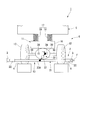
図7に示すように、本実施形態の軌道式車両(車両)の走行台車6Aが備えるアシスト機構15Aは、第一実施形態と同様のアクチュエータ31Aを備える。ただし、本実施形態のアシスト機構15Aでは、アクチュエータ31Aが操舵輪12毎に設けられている。
各アクチュエータ31Aは、第一実施形態と同様のシリンダ本体34及びピストンロッド35を備える。また、各アクチュエータ31Aのピストンロッド35は、第一実施形態の場合と同様に、各アシストアーム36を介して各操舵輪12に連結されている。さらに、各アクチュエータ31Aの動作は、第一実施形態と同様の制御部33(図3参照)からの制御信号に基づいて制御される。
各アクチュエータ31Aは、第一実施形態と同様のシリンダ本体34及びピストンロッド35を備える。また、各アクチュエータ31Aのピストンロッド35は、第一実施形態の場合と同様に、各アシストアーム36を介して各操舵輪12に連結されている。さらに、各アクチュエータ31Aの動作は、第一実施形態と同様の制御部33(図3参照)からの制御信号に基づいて制御される。
本実施形態の走行台車6A及び軌道式車両は、第一実施形態と同様の効果を奏する。
また、本実施形態の走行台車6A及び軌道式車両によれば、単一のアクチュエータ31の補助操舵力を一対の操舵輪12に付与する第一実施形態の構成と比較して、各アクチュエータ31Aにおいて発生させる補助操舵力の大きさを小さくできる。すなわち、第一実施形態の場合と比較して、出力の小さいアクチュエータ31Aを設けることができる。したがって、安価なアクチュエータ31Aによってアシスト機構15Aを構成し、走行台車6Aの製造コスト削減を図ることができる。
また、本実施形態の走行台車6A及び軌道式車両によれば、単一のアクチュエータ31の補助操舵力を一対の操舵輪12に付与する第一実施形態の構成と比較して、各アクチュエータ31Aにおいて発生させる補助操舵力の大きさを小さくできる。すなわち、第一実施形態の場合と比較して、出力の小さいアクチュエータ31Aを設けることができる。したがって、安価なアクチュエータ31Aによってアシスト機構15Aを構成し、走行台車6Aの製造コスト削減を図ることができる。
以上、本発明の詳細について説明したが、本発明は上述した実施形態に限定されるものではなく、本発明の趣旨を逸脱しない範囲において種々の変更を加えることができる。
上記実施形態では、アシスト機構15,15Aの検出部32が、案内装置13の状態として案内装置13の旋回角度を検出しているが、例えば案内装置13が受ける反力を検出してもよい。具体的には、案内装置13の旋回に伴って回転する検出用リンク37の第二端が検出センサ38に押し付けられる力を、反力として検出すればよい。この場合、制御部33は、検出結果である反力に基づいて補助操舵力を設定してもよい。また、制御部33は、検出結果である反力に基づいてアクチュエータ31の変位を算出すればよい。
上記実施形態では、アシスト機構15,15Aの検出部32が、案内装置13の状態として案内装置13の旋回角度を検出しているが、例えば案内装置13が受ける反力を検出してもよい。具体的には、案内装置13の旋回に伴って回転する検出用リンク37の第二端が検出センサ38に押し付けられる力を、反力として検出すればよい。この場合、制御部33は、検出結果である反力に基づいて補助操舵力を設定してもよい。また、制御部33は、検出結果である反力に基づいてアクチュエータ31の変位を算出すればよい。
また、本発明は、上記実施形態のように軌道2の幅方向両端部に設けられたサイドガイド型のガイドレール3によって案内されて走行する走行台車6に限らず、例えば軌道の幅方向中央部に設けられたセンターガイド型のガイドレールによって案内されて走行する走行台車にも適用可能である。
この走行台車によれば、案内装置がガイドレールから受ける反力を小さく抑えながら、幅広の操舵輪を操舵することができる。
1 軌道式車両
2 軌道
3 ガイドレール
5 車体
6,6A 走行台車
11 台車本体
12 操舵輪
13 案内装置
14 操舵機構
15,15A アシスト機構
31,31A アクチュエータ
32 検出部
33 制御部
2 軌道
3 ガイドレール
5 車体
6,6A 走行台車
11 台車本体
12 操舵輪
13 案内装置
14 操舵機構
15,15A アシスト機構
31,31A アクチュエータ
32 検出部
33 制御部
Claims (5)
- 軌道に沿って設けられたガイドレールに案内されて走行する走行台車であって、
操舵輪と、
前記操舵輪を支持する台車本体と、
前記台車本体に回動可能に支持されて、前記ガイドレールからの反力を受けて旋回する案内装置と、
前記案内装置が受けた反力を利用して前記操舵輪に操舵力を付与する操舵機構と、
前記操舵機構による操舵力を補助する補助操舵力を前記操舵輪に付与するアシスト機構と、
を備える走行台車。 - 請求項1に記載の走行台車であって、
前記アシスト機構が、
前記補助操舵力を発生するアクチュエータと、
前記案内装置の状態を検出する検出部と、
前記検出部の検出結果に応じて前記アクチュエータの動作を制御する制御部と、
を備える走行台車。 - 請求項2に記載の走行台車であって、
前記アクチュエータが、前記台車本体に取り付けられている走行台車。 - 請求項2又は請求項3に記載の走行台車であって、
前記操舵輪が、車幅方向に間隔をあけて一対設けられ、
前記アクチュエータが、一対の操舵輪に対して個別に設けられている走行台車。 - 請求項1から請求項4のいずれか一項に記載の走行台車と、
前記走行台車に支持される車体と、
を備える軌道式車両。
Priority Applications (1)
| Application Number | Priority Date | Filing Date | Title |
|---|---|---|---|
| US15/032,302 US10144438B2 (en) | 2013-11-28 | 2014-10-22 | Traveling bogie and track-type vehicle |
Applications Claiming Priority (2)
| Application Number | Priority Date | Filing Date | Title |
|---|---|---|---|
| JP2013245814A JP6222828B2 (ja) | 2013-11-28 | 2013-11-28 | 走行台車及び軌道式車両 |
| JP2013-245814 | 2013-11-28 |
Publications (1)
| Publication Number | Publication Date |
|---|---|
| WO2015079833A1 true WO2015079833A1 (ja) | 2015-06-04 |
Family
ID=53198783
Family Applications (1)
| Application Number | Title | Priority Date | Filing Date |
|---|---|---|---|
| PCT/JP2014/078088 Ceased WO2015079833A1 (ja) | 2013-11-28 | 2014-10-22 | 走行台車及び軌道式車両 |
Country Status (3)
| Country | Link |
|---|---|
| US (1) | US10144438B2 (ja) |
| JP (1) | JP6222828B2 (ja) |
| WO (1) | WO2015079833A1 (ja) |
Cited By (1)
| Publication number | Priority date | Publication date | Assignee | Title |
|---|---|---|---|---|
| CN108482182A (zh) * | 2018-04-17 | 2018-09-04 | 盐城华智超轨道科技有限公司 | 新型悬挂式永磁轨道磁浮交通系统 |
Families Citing this family (15)
| Publication number | Priority date | Publication date | Assignee | Title |
|---|---|---|---|---|
| JP6050156B2 (ja) * | 2013-03-11 | 2016-12-21 | 川崎重工業株式会社 | 案内軌条式車両用案内装置、及び案内軌条式車両 |
| JP5669914B1 (ja) * | 2013-10-18 | 2015-02-18 | 三菱重工業株式会社 | 走行台車、及び軌道系交通システムの車両 |
| US10065663B2 (en) * | 2013-11-22 | 2018-09-04 | Mitsubishi Heavy Industries Engineering, Ltd. | Steering bogie and vehicle |
| JP5868930B2 (ja) * | 2013-11-28 | 2016-02-24 | 三菱重工業株式会社 | 車両用サスペンション装置、走行台車、及び車両 |
| JP6213825B2 (ja) * | 2013-11-28 | 2017-10-18 | 三菱重工業株式会社 | 走行台車及び軌道式車両 |
| JP5730381B1 (ja) * | 2013-12-12 | 2015-06-10 | 三菱重工業株式会社 | 案内輪、走行台車、及び車両 |
| CN110116584B (zh) * | 2018-02-06 | 2022-03-18 | 比亚迪股份有限公司 | 轨道车辆的驱动桥、轨道车辆和轨道交通系统 |
| CN110116585B (zh) | 2018-02-06 | 2022-03-15 | 比亚迪股份有限公司 | 轨道车辆的非驱动桥、轨道车辆和轨道交通系统 |
| JP6899345B2 (ja) * | 2018-02-23 | 2021-07-07 | 三菱重工エンジニアリング株式会社 | 台車、及び車両 |
| CN111517050B (zh) * | 2019-02-03 | 2023-05-02 | 北京京东乾石科技有限公司 | 运输车及其传动装置 |
| JP7130573B2 (ja) * | 2019-02-20 | 2022-09-05 | 三菱重工エンジニアリング株式会社 | 移動体制御装置、移動体、移動体制御方法及びプログラム |
| JP7190946B2 (ja) * | 2019-03-20 | 2022-12-16 | 三菱重工エンジニアリング株式会社 | 電源装置、自動操舵車両、及び電力供給方法 |
| CN113335327B (zh) * | 2020-03-03 | 2023-06-13 | 比亚迪股份有限公司 | 转向架以及具有其的轨道车辆、轨道交通系统 |
| CN114454910B (zh) * | 2021-12-03 | 2023-07-25 | 山东东铁动力科技有限公司 | 轨道车辆测试用牵引救援车底盘及其牵引救援车 |
| GB202301071D0 (en) | 2023-01-25 | 2023-03-08 | Heavy Lift Projects Ltd | Ring crane with hydraulic slewing drive |
Citations (7)
| Publication number | Priority date | Publication date | Assignee | Title |
|---|---|---|---|---|
| JPS4942610U (ja) * | 1972-07-18 | 1974-04-15 | ||
| JPS5214885B2 (ja) * | 1971-11-29 | 1977-04-25 | ||
| JPS53140715A (en) * | 1977-05-11 | 1978-12-08 | Daimler Benz Ag | Traffic system for vehicles having wheels capable of being steered and guided on rail |
| JPS5724600Y2 (ja) * | 1979-06-13 | 1982-05-28 | ||
| JPH0141547B2 (ja) * | 1978-04-28 | 1989-09-06 | Daimler Benz Ag | |
| US6477963B1 (en) * | 1999-03-12 | 2002-11-12 | Bombardier Transportaion Gmbh | Apparatus and method for steering a guideway vehicle |
| WO2013094336A1 (ja) * | 2011-12-19 | 2013-06-27 | 三菱重工業株式会社 | 交通システム |
Family Cites Families (4)
| Publication number | Priority date | Publication date | Assignee | Title |
|---|---|---|---|---|
| JP4808507B2 (ja) | 2006-02-16 | 2011-11-02 | 公益財団法人鉄道総合技術研究所 | 鉄道車両用軸箱アシスト操舵台車 |
| JP5249509B2 (ja) * | 2006-11-10 | 2013-07-31 | 三菱重工業株式会社 | 軌道系交通システムの分岐装置 |
| JP5107280B2 (ja) | 2009-02-26 | 2012-12-26 | 三菱重工業株式会社 | 軌道系車両用台車 |
| JP5291503B2 (ja) | 2009-03-17 | 2013-09-18 | 三菱重工業株式会社 | 軌道系車両用台車 |
-
2013
- 2013-11-28 JP JP2013245814A patent/JP6222828B2/ja not_active Expired - Fee Related
-
2014
- 2014-10-22 WO PCT/JP2014/078088 patent/WO2015079833A1/ja not_active Ceased
- 2014-10-22 US US15/032,302 patent/US10144438B2/en active Active
Patent Citations (7)
| Publication number | Priority date | Publication date | Assignee | Title |
|---|---|---|---|---|
| JPS5214885B2 (ja) * | 1971-11-29 | 1977-04-25 | ||
| JPS4942610U (ja) * | 1972-07-18 | 1974-04-15 | ||
| JPS53140715A (en) * | 1977-05-11 | 1978-12-08 | Daimler Benz Ag | Traffic system for vehicles having wheels capable of being steered and guided on rail |
| JPH0141547B2 (ja) * | 1978-04-28 | 1989-09-06 | Daimler Benz Ag | |
| JPS5724600Y2 (ja) * | 1979-06-13 | 1982-05-28 | ||
| US6477963B1 (en) * | 1999-03-12 | 2002-11-12 | Bombardier Transportaion Gmbh | Apparatus and method for steering a guideway vehicle |
| WO2013094336A1 (ja) * | 2011-12-19 | 2013-06-27 | 三菱重工業株式会社 | 交通システム |
Cited By (1)
| Publication number | Priority date | Publication date | Assignee | Title |
|---|---|---|---|---|
| CN108482182A (zh) * | 2018-04-17 | 2018-09-04 | 盐城华智超轨道科技有限公司 | 新型悬挂式永磁轨道磁浮交通系统 |
Also Published As
| Publication number | Publication date |
|---|---|
| JP2015101312A (ja) | 2015-06-04 |
| US20160264156A1 (en) | 2016-09-15 |
| US10144438B2 (en) | 2018-12-04 |
| JP6222828B2 (ja) | 2017-11-01 |
Similar Documents
| Publication | Publication Date | Title |
|---|---|---|
| JP6222828B2 (ja) | 走行台車及び軌道式車両 | |
| US8353248B2 (en) | Track-guided vehicle wheel track | |
| CN102361788B (zh) | 轨道引导车辆用台车 | |
| US8381660B2 (en) | Track-guided vehicle wheel truck | |
| KR101205164B1 (ko) | 철도 차량용 조타 대차, 철도 차량 및 연접 차량 | |
| JP6274115B2 (ja) | 車両、及び、軌道系交通システム | |
| WO2013094336A1 (ja) | 交通システム | |
| JP6213825B2 (ja) | 走行台車及び軌道式車両 | |
| WO2014171389A1 (ja) | ステアリング装置、そのステアリング装置を用いた車両、及び、4輪転舵機構を備えた車両 | |
| JP4930171B2 (ja) | 案内軌条式車両操舵系の振動制御方法及び装置 | |
| JP4808507B2 (ja) | 鉄道車両用軸箱アシスト操舵台車 | |
| JP4505508B2 (ja) | 後輪トー角可変車両 | |
| WO2019163153A1 (ja) | 台車、及び車両 | |
| JP2000264198A (ja) | モノレール車両用台車及びモノレール車両 | |
| JP4567068B2 (ja) | 後輪トー角可変車両 | |
| WO2016098316A1 (ja) | 鉄道車両用の操舵台車 | |
| JP2007168510A (ja) | 鉄道車両用アシストボギー角操舵台車 | |
| JP4877036B2 (ja) | 案内軌条式車両の操舵装置 | |
| JP2016132430A (ja) | ステアリング装置 | |
| KR20140001470A (ko) | 후륜 조향 현가장치 | |
| JP2009234328A (ja) | 鉄道車両用操舵台車 |
Legal Events
| Date | Code | Title | Description |
|---|---|---|---|
| 121 | Ep: the epo has been informed by wipo that ep was designated in this application |
Ref document number: 14865590 Country of ref document: EP Kind code of ref document: A1 |
|
| WWE | Wipo information: entry into national phase |
Ref document number: 15032302 Country of ref document: US |
|
| NENP | Non-entry into the national phase |
Ref country code: DE |
|
| 122 | Ep: pct application non-entry in european phase |
Ref document number: 14865590 Country of ref document: EP Kind code of ref document: A1 |