WO2015075877A1 - 放射線検出装置および放射線撮像システム - Google Patents
放射線検出装置および放射線撮像システム Download PDFInfo
- Publication number
- WO2015075877A1 WO2015075877A1 PCT/JP2014/005526 JP2014005526W WO2015075877A1 WO 2015075877 A1 WO2015075877 A1 WO 2015075877A1 JP 2014005526 W JP2014005526 W JP 2014005526W WO 2015075877 A1 WO2015075877 A1 WO 2015075877A1
- Authority
- WO
- WIPO (PCT)
- Prior art keywords
- radiation detection
- light source
- radiation
- panel
- source unit
- Prior art date
- Legal status (The legal status is an assumption and is not a legal conclusion. Google has not performed a legal analysis and makes no representation as to the accuracy of the status listed.)
- Ceased
Links
Images





Classifications
-
- A—HUMAN NECESSITIES
- A61—MEDICAL OR VETERINARY SCIENCE; HYGIENE
- A61B—DIAGNOSIS; SURGERY; IDENTIFICATION
- A61B6/00—Apparatus or devices for radiation diagnosis; Apparatus or devices for radiation diagnosis combined with radiation therapy equipment
- A61B6/42—Arrangements for detecting radiation specially adapted for radiation diagnosis
- A61B6/4283—Arrangements for detecting radiation specially adapted for radiation diagnosis characterised by a detector unit being housed in a cassette
Definitions
- the present invention relates to a radiation detection apparatus and a radiation imaging system.
- the present invention relates to a radiation detection apparatus using a radiation detection panel that converts radiation into an electrical signal according to its intensity, and a radiation imaging system to which the radiation detection apparatus is applied.
- a radiation detection panel (a so-called flat panel detector (FPD)) in which a scintillator and a large-area solid-state imaging device are in close contact with each other has a characteristic that causes a characteristic variation due to long-time use and a decrease in S / N ratio due to a dark current.
- FPD flat panel detector
- Patent Document 1 discloses a configuration in which the solid detector side faces the radiation incident side in order to improve the detection efficiency of visible light in the solid state detector and improve the image quality of the obtained radiographic image. Has been.
- Patent Document 1 countermeasures against external impacts and vibrations are not sufficiently studied, and in some cases, the radiation detection panel may be damaged by the light irradiation means.
- the present invention has been made in view of the above problems, and in a radiation detection apparatus having an improvement in image quality and afterimage characteristics of a radiation detection panel, breakage due to impact, vibration, or the like can be suppressed.
- the present invention provides a radiation detection panel having a plurality of photoelectric conversion elements disposed on a first surface of a substrate, and a scintillator disposed on the first surface side of the substrate; A light source unit that is disposed on the second surface side opposite to the first surface of the substrate, irradiates light to the plurality of photoelectric conversion elements, and a surface facing the light source unit to the plurality of photoelectric conversion elements.
- a box that includes a corresponding opening, a lid that allows the radiation detection panel to transmit radiation provided to cover the opening, and a housing that contains the radiation detection panel and the light source, and the lid And a light source support part that supports the light source part so as to be displaceable in a direction orthogonal to the second surface between the part and the second surface.
- the light source part is supported by the light source support part so as to be displaceable, the impact transmitted to the light source part is reduced, so that the radiation detection panel can be prevented from being damaged.
- (First embodiment) In the first embodiment, as a light source support unit for supporting the light source unit, a buffer member provided on the inner surface of the housing on which radiation is incident and a light source support for supporting the light source unit from the side opposite to the side on which radiation is incident And a mechanism.
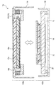
- FIG. 1 is a schematic cross-sectional view of a configuration example of a radiation detection apparatus 1a according to the first embodiment.
- the radiation detection apparatus 1a includes a housing 11 including an upper cover 111 (cover portion) and a frame 112 (frame portion) that are examples of a box portion, and a housing lid 113 that is an example of a lid portion.
- the housing 11 includes the buffer sheet 16a, the light source unit 17a, the radiation detection panel 12, the chassis 13, and the electric board 14. Furthermore, the housing 11 includes light source holding means for holding the light source unit 17a.
- the housing 11 has a configuration capable of detecting radiation incident from the side of the upper cover 111 that is an example of the cover portion of the box portion.
- An arrow X in the figure shows an example of the direction of incident radiation.
- a radiation incident area A is set in the radiation detection apparatus 1a.
- the radiation incident area A is an area where radiation transmitted through a patient, a subject, or the like is incident, and corresponds to an area where photoelectric conversion elements 122 (described later) of the radiation detection panel 12 are arranged in a plan view.
- the upper cover 111 which is an example of the cover part, and the frame 112, which is an example of the frame part, have a separable configuration, and are joined to each other so as to be separable, for example.
- the upper cover 111 has an opening in a region corresponding to the radiation incident region A.
- the housing cover 113 is joined so that this opening may be covered.
- the case lid 113 is made of a material having high radiation transmittance such as CFRP.
- the radiation detection panel 12 includes a substrate 121, a photoelectric conversion element 122, a scintillator 123, and a reflection sheet 124, and has a configuration in which these are stacked.
- a glass plate can be applied because it has no chemical action with a semiconductor element, can withstand the temperature of a semiconductor process, and has dimensional stability.
- the photoelectric conversion elements 122 are formed on one surface which is an example of the first surface of the substrate 121 so as to be two-dimensionally arranged by a semiconductor process.
- a scintillator 123 that converts radiation into light is joined to the first surface side and above the photoelectric conversion element 122.
- the scintillator 123 is covered with a reflection sheet 124 made of a metal such as aluminum that easily reflects light.
- the radiation detection panel 12 is fixed to the chassis 13 in such a direction that the substrate 121 is located on the radiation incident side and the scintillator 123 is located on the opposite side to the radiation incidence side. With such a configuration, the light detection efficiency of the photoelectric conversion element 122 is improved, and the sharpness of the obtained image can be further improved.
- the chassis 13 is an example of a panel support portion, and is a member that supports the radiation detection panel 12.
- the radiation detection panel 12 is supported on one surface of the chassis 13 (a surface facing the side on which the radiation is incident).
- a plurality of legs 131 are provided on the surface opposite to the surface that supports the radiation detection panel 12. These leg portions 131 are joined to the inner surface of the frame 112. Thereby, the radiation detection panel 12 is positioned inside the housing 11.
- the radiation detection panel 12 has a square shape in plan view.
- One end of a flexible printed wiring board (FPC) 20 is connected to at least one of the four sides of the radiation detection panel 12.
- the other end of the FPC 20 is connected to the electric board 14.
- a space is formed by the legs 131 on the opposite side of the chassis 13 from which the radiation is incident.
- substrate 14 is arrange
- the light source unit 17a emits refreshing light that improves the afterimage characteristics of the radiation detection panel 12. For example, the light source unit 17 a removes charges accumulated in the radiation detection panel 12 by irradiating the radiation detection panel 12 with light.
- an LED backlight that has been used in a liquid crystal television or the like with high output, small size, and low price in recent years can be used.
- the light source unit 17a includes, for example, a four-layer optical member including a reflection sheet 171, a light guide plate 172, a diffusion sheet 173, and a diffusion sheet 174a, and has a configuration in which these optical members are laminated.
- a plurality of light emitting elements 175 that emit refreshing light are arranged on the side surface of the light guide plate 172.
- the light emitting element 175 and the electric board 14 are connected by a cable (not shown), and the light emitting element 175 is turned on in response to an electric signal from the electric board 14.
- the light source part 17a is arrange
- FIG. And the light source part 17a is clamped by the buffer sheet 16a (buffer member) which is an example of a light source support part, and the light source support mechanism 18a so that a displacement in the direction orthogonal to the 2nd surface of the radiation detection panel 12 is possible.
- the buffer sheet 16a which is an example of the buffer member of the light source support part, alleviates the impact and vibration transmitted from the outside of the housing 11 to the light source part 17a.
- a urethane foam material is applied to the buffer sheet 16a.
- the buffer sheet 16 a is disposed on the inner surface side of the housing lid 113 and is interposed between the radiation detection panel 12 and the inner surface of the housing lid 113.
- the buffer sheet 16a is provided in the radiation incident area A in plan view.
- the whole surface by the side of the housing lid 113 of the light source part 17a is covered with the buffer sheet 16a.
- the light source support mechanism 18a is joined to the inner surface of the upper cover 111 on the side on which the radiation is incident. And the light source support mechanism 18a supports the light source part 17a so that a displacement from the radiation detection panel 12 side is possible. Further, the light source support mechanism 18a supports at least a part of the light source unit 17a from the radiation detection panel 12 side.
- the light source support mechanism 18a incorporates an attenuation mechanism 181 that attenuates an impact from a direction orthogonal to the surface direction of the light source portion 17a.
- a known telescopic damper or a combination of an telescopic damper and a spring can be applied.
- the telescopic damper is disposed so that the telescopic direction thereof is orthogonal to the second surface of the radiation detection panel 12.
- the buffer sheet 16a which is an example of the light source support means, and the light source support mechanism 18a sandwich the light source unit 17a so as to be displaceable in a direction perpendicular to the second surface of the radiation detection panel 12.
- the light source unit 17a is disposed with a gap (that is, an air layer B) between the radiation detection panel 12 and the light source unit 17a. According to such a configuration, it is possible to prevent an impact from a direction orthogonal to the second surface of the radiation detection panel 12 or the like from being directly transmitted from the light source unit 17a to the radiation detection panel 12. Therefore, even if the light source unit 17a is displaced due to external impact or vibration, the light source unit 17a does not contact the radiation detection panel 12, and therefore the radiation detection panel 12 can be prevented from being damaged.
- the entire surface of the light source unit 17a is covered with the buffer sheet 16a. For this reason, the shock and vibration transmitted to the light source unit 17a are alleviated by the buffer sheet 16a.
- the radiation detection panel 12 and the light source unit 17a are not bonded. Therefore, even if the thermal expansion coefficients of the radiation detection panel 12 and the light source unit 17a are different, no thermal stress is generated in the radiation detection panel 12 and the light source unit 17a. Therefore, damage to the radiation detection panel and the light source unit 17a due to temperature change can be prevented.
- FIG. 2 is a schematic view showing a state in which the radiation detection apparatus 1a is separated into an upper cover portion 101a and a panel support portion 102a.
- the upper cover portion 101a includes an upper cover 111, a case lid 113, and a light source portion 17a.
- the panel support portion 102a includes the frame 112 and the radiation detection panel 12.
- the radiation detection panel 12 and the light source unit 17a are not bonded.
- the light source unit 17 a is supported by the upper cover 111 by the light source support mechanism 18 a, and the radiation detection panel 12 is supported by the chassis 13 joined to the frame 112. Therefore, as shown in FIG. 2, the radiation detection apparatus 1a can be separated into an upper cover portion 101a and a panel support portion 102a. With such a configuration, the workability of replacement and maintenance of the radiation detection panel 12 and the light source unit 17a is improved.
- the second buffer means for supporting the light source unit 17a is provided in the chassis 13 which is an example of the panel support unit.
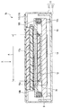
- FIG. 3 is a schematic cross-sectional view showing a configuration example of the radiation detection apparatus 1b according to the second embodiment of the present invention.
- the light source support mechanism 18b is joined to the upper cover 111 side (the side on which radiation is incident) of the chassis 13.
- An attenuation mechanism 181 is incorporated in the light source support mechanism 18b, and supports the light source unit 17a so that it can be displaced in a direction perpendicular to the second surface of the radiation detection panel 12.
- the light source unit 17a is sandwiched between the light source support mechanism 18b and the upper cover 111.
- an air layer B is provided between the light source unit 17a and the radiation detection panel 12, and is not in direct contact. According to such a configuration, the same effects as those of the first embodiment can be obtained.
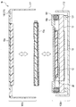
- FIG. 4 is a schematic diagram showing a state in which the radiation detection apparatus 1b is separated into an upper cover portion 101b and a panel support portion 102b.
- the radiation detection apparatus 1b can be separated into the upper cover part 101b and the panel support part 102b.
- the light source unit 17a is supported by the upper cover unit 101a.
- the light source unit 17a is sandwiched between the upper cover 111 and the panel support unit 102b. There is only. For this reason, when the radiation detection apparatus 1b is separated into the upper cover part 101b and the panel support part 102b, the light source part 17a is separated from both the upper cover part 101a and the panel support part 102b.
- the light source unit 17a can be easily attached to and detached from the housing 11. Therefore, it is possible to provide the radiation detection apparatus 1b that is excellent in workability for replacement and maintenance of the light source unit 17a and that suppresses shock and vibration from a direction orthogonal to the second surface of the radiation detection panel 12.
- the third buffering mechanism that supports the light source unit from the side opposite to the side on which the radiation of the housing is incident includes the light source unit, the surface direction of the second surface of the radiation detection panel 12, and this surface. It is the form which supports so that a displacement in the direction orthogonal to a direction is possible.
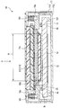
- FIG. 5 is a schematic cross-sectional view showing a configuration example of the radiation detection apparatus 1c according to the third embodiment.
- the light source support mechanism 18 c is joined to the side wall of the upper cover 111.
- the side wall of the upper cover 111 refers to a standing wall-like portion provided so as to surround the surface on which the radiation incident area A is set.
- the radiation detection panel 12 and the light source unit 17a are not in direct contact, and an air layer B is provided between them.
- FIG. 6 is a schematic diagram showing a state in which the radiation detection apparatus 1c is separated into the upper cover portion 101c and the panel support portion 102c.
- the radiation detection apparatus 1c can be separated into an upper cover part 101c provided with a light source part 17a and a panel support part 102c provided with a radiation detection panel 12. Therefore, as in the first embodiment, the radiation detection apparatus 1c is excellent in workability for replacement and maintenance of the light source unit 17a, and can reduce impact and vibration from a direction orthogonal to the second surface of the radiation detection panel 12. Can provide.
- the light source support mechanism 18c supports the light source unit 17a so as to be displaceable in two directions, ie, a direction parallel to the surface direction of the second surface of the radiation detection panel 12 and a direction perpendicular to the surface direction.
- the light source support mechanism 18 c includes two attenuation mechanisms 181 and 182.
- One attenuation mechanism 181 is provided in the other attenuation mechanism 182, and supports the light source unit 17 a so as to be displaceable in a direction orthogonal to the second surface of the radiation detection panel 12.
- the other attenuation mechanism 182 is provided on the inner surface of the side wall of the upper cover 111, and supports the one attenuation mechanism 181 so as to be displaceable in a direction parallel to the second surface of the radiation detection panel 12.
- Each of the two damping mechanisms 181 and 182 can be applied with a telescopic damper or a combination of a telescopic damper and a spring.
- the telescopic damper as the one attenuation mechanism 181 is arranged so that the expansion / contraction direction thereof is parallel to the direction orthogonal to the second surface of the radiation detection panel 12.
- the telescopic damper as the other attenuation mechanism 182 is disposed so that the expansion / contraction direction thereof is parallel to the second surface of the radiation detection panel 12.
- the light source support mechanism 18c having such a configuration, it is possible to reduce the impact transmitted to the light source unit 17a from two directions, ie, a direction parallel to the second surface of the radiation detection panel 12 and a direction orthogonal thereto. Therefore, damage to the light source unit 17a can be prevented.
- a stopper for restricting the displacement of the light source unit is provided.
- FIG. 7 is a schematic cross-sectional view showing a configuration example of a radiation detection apparatus 1d according to the fourth embodiment. Also in the fourth embodiment, the radiation detection panel 12 and the light source unit 17a are not in contact with each other, and an air layer B is provided between them. In the fourth embodiment, as shown in FIG. 7, a stopper 19 is provided between the light source support mechanism 18 a and the chassis 13 in addition to the configuration of the first embodiment. The stopper 19 regulates the displacement of the light source support mechanism 18a (that is, the displacement of the light source unit 17a) and prevents the light source unit 17a from contacting the radiation detection panel 12.
- the stopper 19 is a surface of the chassis 13 facing the radiation incident area A, and is provided at a position overlapping the light source support mechanism 18a in plan view. Further, the stopper 19 and the light source support mechanism 18a are not in contact with each other and are separated from each other with a predetermined gap.
- the dimension (distance) of the gap between the stopper 19 and the light source support mechanism 18a is set smaller than the dimension of the gap between the radiation detection panel 12 and the light source unit 17a (that is, the thickness of the air layer B).
- the light source support mechanism 18 a is applied to the stopper 19.
- the contact between the radiation detection panel 12 and the light source unit 17a is prevented. Therefore, damage to the light source unit 17a and the radiation detection panel 12 can be prevented.
- the fifth embodiment is a form in which a buffer sheet, which is an example of a buffer member, is provided outside a region (radiation incident region A) corresponding to the photoelectric conversion element 122 of the radiation detection panel 12 in a plan view.
- FIG. 8 is a schematic cross-sectional view showing a configuration example of a radiation detection apparatus 1e according to the fifth embodiment of the present invention.
- the buffer sheet 16e is disposed outside the radiation incident area A in plan view.
- the buffer sheet 16e has an opening at a portion corresponding to the radiation incident area A.
- the housing lid 113 is deformed in the above-described direction by an impact from a direction orthogonal to the second surface of the radiation detection panel 12, if the thickness of the buffer sheet 16e is larger than the deformation amount, The inner surface of the case lid 113 does not contact the light source unit 17a. Therefore, damage to the light source unit 17a can be prevented.
- a buffer sheet which is an example of a buffer member, is not provided between the light source unit and the housing lid (the inner surface of the housing where the radiation enters).
- FIG. 9 is a schematic cross-sectional view showing a configuration example of a radiation detection apparatus 1f according to the sixth embodiment of the present invention.
- the light source part 17a is comprised with a material with high impact resistance, and a buffer sheet is not provided.
- the light guide plate 172 of the light source unit 17a is formed of a material that is light transmissive and resistant to impact. As such a material, for example, polycarbonate (PC) is applied.
- the housing lid 113 is joined to the inner side of the upper cover 111. And the light source part 17a is clamped by the light source support mechanism 18a and the housing lid 113 so that displacement is possible.
- the casing lid 113 and the light source unit 17a may be sandwiched between the upper cover 111 and the light source support mechanism 18a so as to be displaceable. According to such a structure, since the structure of the radiation detection apparatus 1f can be simplified, size reduction is attained.
- FIG. 10 is a schematic cross-sectional view illustrating a configuration example of a radiation detection apparatus 1g according to the seventh embodiment.
- a part of an optical member constituting the light source unit 17g is formed of a material having translucency and flexibility, and the optical member having flexibility has a function of a light source support unit. It is.
- the diffusion sheet 174g is made of a material having translucency and flexibility. As such a material, for example, polycarbonate (PC) or polypropylene (PP) is applied. Further, as shown in FIG. 10, the diffusion sheet 174g is formed to a size that can cover the entire light source portion 17g.
- PC polycarbonate
- PP polypropylene
- the diffusion sheet 174g is disposed on the radiation detection panel 12 side, and the peripheral edge thereof is joined to the inner surface of the upper cover 111.
- the light source unit 17g is supported by the upper cover 111 by the diffusion sheet 174g, which is an example of a flexible optical member, with the entire surface thereof in contact with the buffer sheet 16a.
- the function similar to a buffer mechanism (damper) can be provided to the diffusion sheet 174g by adjusting the tension
- the tension applied to the diffusion sheet 174g can be adjusted by appropriately setting the elastic coefficient of the material of the diffusion sheet 174g and the attachment angle of the sheet.
- an air layer B is provided as in the other embodiments.
- the light source unit 17g can be easily attached to and detached from the upper cover 111.
- exchange and maintenance of the radiation detection panel 12 and the light source part 17g improves like 1st Embodiment.
- the configuration is simple compared to the first embodiment. For this reason, size reduction and cost reduction can be achieved.
- the light source unit and the radiation detection panel are supported so as to move in a coordinated manner.
- FIG. 11 is a schematic cross-sectional view showing a configuration example of a radiation detection apparatus 1h according to the eighth embodiment.
- the chassis 13 is provided on the frame 112 via the chassis support mechanism 22.
- the chassis support mechanism 22 supports the radiation detection panel 12 so as to be displaceable in a direction orthogonal to the second surface.
- the chassis support mechanism 22 incorporates an attenuation mechanism 221 capable of attenuating an impact from a direction orthogonal to the second surface of the radiation detection panel 12.
- a telescopic damper or a combination of a telescopic damper and a coil spring is applied.
- the telescopic damper is provided so that its telescopic direction is parallel to a direction orthogonal to the second surface of the radiation detection panel 12.
- One of the telescopic damper body and the telescopic shaft is joined to the inner surface of the frame 112, and the other is joined to the chassis 13.
- the radiation detection panel 12 is supported by the attenuation mechanism 221 so as to be displaceable in a direction perpendicular to the second surface. According to such a configuration, the impact in the direction orthogonal to the second surface of the radiation detection panel 12 can be mitigated, and damage to the radiation detection panel 12 can be prevented.
- the radiation detection panel 12 and the light source unit 17a move in cooperation by the attenuation mechanism 181 and the attenuation mechanism 221.
- the radiation detection panel 12 and the light source unit 17a can move in the radiation incident direction while closely contacting each other.
- FIG. 11 shows a configuration in which an air layer B is provided between the radiation detection panel 12 and the light source unit 17a as in the other embodiments, but the radiation detection panel 12 and the light source unit 17a cooperate with each other.
- the air layer B may not be provided as long as it is movable. According to such a configuration, the radiation detection panel 12 can be irradiated with the refreshing light emitted from the light source unit 17a without being attenuated. For this reason, the power saving of the light source part 17a can be achieved.
- FIG. 12 is a schematic diagram showing a schematic configuration of the radiation imaging system according to the embodiment of the present invention.
- the radiation detection apparatuses 1a to 1h according to any one of the above embodiments are applied to the radiation imaging system according to the present embodiment.
- X-ray tube 6050 which is an example of radiation generating means, generates X-ray 6060, which is an example of radiation.
- the X-ray 6060 passes through the imaging target region (shown here as the chest 6062) of the patient or subject 6061 and enters the radiation detection devices 1a to 1h, which are examples of radiation detection means.
- the X-rays incident on the radiation detection apparatuses 1a to 1h include information inside the body of the patient or the subject 6061.
- the scintillator 123 emits light corresponding to the incidence of X-rays.
- the photoelectric conversion element 122 of the radiation detection panel 12 photoelectrically converts light emitted by the scintillator 123 in response to X-rays.
- a signal processing circuit is provided on the electric substrate 14 of the radiation detection apparatuses 1a to 1h.
- the signal processing circuit converts the electric signal into a digital format and transmits the digital signal to an image processor 6070 which is an example of signal processing means.
- the image processor 6070 performs predetermined signal processing such as image processing on the transmitted electrical signal, and outputs and displays the signal on a display 6080 which is an example of display means provided in the control room. For this reason, the examiner or the like can observe information inside the body of the patient or the subject 6061 as an image.
- the image processor 6070 can transfer this electric signal to a remote place via a network 6090 such as a telephone, a LAN, or the Internet which is an example of a transmission means.
- the image processor 6070 can transmit the electrical signal to a display 6081 that is an example of a display unit provided in a doctor room at another location and the like to display the electrical signal. Or it can preserve
- it can also record on the film 6010 by the film processor 6100 which is an example of a recording means.
- the image processor 6070 can transmit this electrical signal to the film processor 6100.
- the film processor 6100 can create a film 6010 including information inside the body of the patient or the subject 6061 from the received electrical signal using a laser printer.
Landscapes
- Health & Medical Sciences (AREA)
- Life Sciences & Earth Sciences (AREA)
- Medical Informatics (AREA)
- Engineering & Computer Science (AREA)
- Radiology & Medical Imaging (AREA)
- Molecular Biology (AREA)
- Biophysics (AREA)
- Nuclear Medicine, Radiotherapy & Molecular Imaging (AREA)
- Optics & Photonics (AREA)
- Pathology (AREA)
- Physics & Mathematics (AREA)
- Biomedical Technology (AREA)
- Heart & Thoracic Surgery (AREA)
- High Energy & Nuclear Physics (AREA)
- Surgery (AREA)
- Animal Behavior & Ethology (AREA)
- General Health & Medical Sciences (AREA)
- Public Health (AREA)
- Veterinary Medicine (AREA)
- Measurement Of Radiation (AREA)
- Apparatus For Radiation Diagnosis (AREA)
Abstract
放射線検出装置は、基板の第1面に配置された複数の光電変換素子と基板の第1面側に配置されたシンチレータとを有する放射線検出パネルと、基板の第1面は反対側の第2面側に配置され複数の光電変換素子に光を照射する光源部と、光源部と対向する面に複数の光電変換素子に対応した開口を有する箱部と開口を覆うように設けられた放射線を放射線検出パネルに透過させる蓋部とを含み放射線検出パネル及び光源部を内包する筐体と、蓋部と第2面との間において第2面と直交する方向に変位可能に光源部を支持する光源支持部とを有する。
Description
本発明は、放射線検出装置および放射線撮像システムに関する。特には、放射線をその強度に応じて電気信号に変換する放射線検出パネルを用いた放射線検出装置と、この放射線検出装置が適用される放射線撮像システムに関する。
シンチレータと大面積固体撮像素子を密着させた放射線検出パネル(いわゆるフラットパネルディテクタ(FPD))は、長時間の使用による特性変動や、ダーク電流によるS/N比の低下を招くという特性を有する。特許文献1では、このような特性を改善するため、放射線検出パネルの各素子に光を照射する光源を有する装置が提案されている。また、特許文献1では、固体検出器における可視光の検出効率を高め、得られる放射線画像の画質を向上させるために、固体検出器側が放射線入射側の面を向くように配置される構成が開示されている。
特許文献1では、外部からの衝撃や振動に対する対策が十分に検討されておらず、場合によっては光照射手段によって放射線検出パネルが破損するおそれがある。
本発明は、上記課題を鑑みてなされたものであり、放射線検出パネルの画質の向上と残像特性の改善手段を有する放射線検出装置において、衝撃や振動などによる破損を抑制することができる。
上記目的を達成するため、本発明は、基板の第1面に配置された複数の光電変換素子と、前記基板の前記第1面の側に配置されたシンチレータと、を有する放射線検出パネルと、前記基板の前記第1面とは反対側の第2面側に配置され、前記複数の光電変換素子に光を照射する光源部と、前記光源部と対向する面に前記複数の光電変換素子に対応した開口を有する箱部と、前記開口を覆うように設けられた放射線を前記放射線検出パネルに透過させる蓋部と、を含み、前記放射線検出パネルおよび前記光源部を内包する筺体と、前記蓋部と前記第2面との間において前記第2面と直交する方向に変位可能に前記光源部を支持する光源支持部と、を有することを特徴とする。
本発明によれば、光源部が光源支持部によって変位可能に支持されることによって、光源部に伝わる衝撃が緩和されるため、放射線検出パネルの破損を抑制できる。
(第1の実施形態)
第1の実施形態は、光源部を支持する光源支持部として、筺体の放射線が入射する側の内面に設けられる緩衝部材と、光源部を放射線が入射する側とは反対側から支持する光源支持機構とを有する形態である。
第1の実施形態は、光源部を支持する光源支持部として、筺体の放射線が入射する側の内面に設けられる緩衝部材と、光源部を放射線が入射する側とは反対側から支持する光源支持機構とを有する形態である。
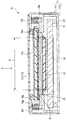
図1は、第1の実施形態における放射線検出装置1aの構成例の断面模式図である。
放射線検出装置1aは、箱部の例である上カバー111(カバー部)およびフレーム112(フレーム部)と、蓋部の例である筺体蓋113とで構成される筺体11を有する。そして、筺体11は、緩衝シート16aと、光源部17aと、放射線検出パネル12と、シャシー13と、電気基板14とを内包する。さらに、筺体11は、光源部17aを保持する光源保持手段を内包する。
本実施形態においては、筺体11は、箱部のカバー部の例である上カバー111の側から入射した放射線を検出できる構成を有する。図中の矢印Xは、入射する放射線の方向の一例を示す。なお、放射線検出装置1aには、放射線の入射領域Aが設定される。放射線の入射領域Aは、患者や被検者などを透過した放射線が入射する領域であり、平面視において、放射線検出パネル12の光電変換素子122(後述)が配列される領域に対応する。
カバー部の例である上カバー111とフレーム部の例であるフレーム112とは、分離可能な構成を有し、例えば互いに分離可能に接合される。そして、上カバー111には、放射線の入射領域Aに対応する領域に開口が形成される。そして、この開口を覆うように、筺体蓋113が接合される。筺体蓋113は、CFRPなどの放射線の透過率が高い材料により形成される。
放射線検出パネル12は、基板121と、光電変換素子122と、シンチレータ123と、反射シート124とを有し、これらが積層された構成を有する。
基板121としては、半導体素子との化学作用のないこと、半導体プロセスの温度に耐えること、寸法安定性等の必要性からガラス板を適用することができる。光電変換素子122は、基板121の第1面の例である一方の表面に、半導体プロセスにより二次元的に配列されるように形成される。第1面側であって光電変換素子122の上側には、放射線を光に変換するシンチレータ123が接合される。シンチレータ123は、光を反射しやすいアルミ等の金属からなる反射シート124で覆われている。
放射線検出パネル12は、その基板121が放射線の入射される側に位置し、そのシンチレータ123が放射線の入射する側とは反対側に位置する向きで、シャシー13に固定されている。このような構成であると、光電変換素子122による光の検出効率が向上し、更に得られた画像の鮮鋭度を向上させることができる。
シャシー13は、パネル支持部の例であり、放射線検出パネル12を支持する部材である。放射線検出パネル12は、シャシー13の一方の面(放射線が入射する側を向く面)に支持される。放射線検出パネル12を支持する面とは反対側の面には、複数の脚部131が設けられる。これら脚部131は、フレーム112の内面に接合されている。これにより、放射線検出パネル12は、筺体11の内部において位置決めされている。
放射線検出パネル12は、平面視において四角の形状をなす。そして放射線検出パネル12の4辺のうちの少なくとも1辺には、フレキシブルプリント配線板(FPC)20の一端が接続されている。FPC20の他端は、電気基板14に接続されている。シャシー13の放射線が入射する側とは反対側には、脚部131によって空間が形成される。そして、電気基板14は、この空間に配置される。
光源部17aは、放射線検出パネル12の残像特性を改善するリフレッシュ光を発する。たとえば、光源部17aは、放射線検出パネル12に光を照射することよって、放射線検出パネル12にたまった電荷を除去する。光源部17aとしては、近年、高出力、小型、低価格化が進み、液晶テレビ等でも多く使用されているLEDバックライトを用いることができる。光源部17aは、たとえば、反射シート171と、導光板172と、拡散シート173と、拡散シート174aとの4層の光学部材を含み、これらの光学部材が積層された構成を有する。導光板172の側面には、リフレッシュ光を発する発光素子175が複数配列されている。発光素子175と電気基板14とはケーブル(図略)で接続されており、発光素子175は、電気基板14からの電気信号に応じて点灯する。
光源部17aは、放射線検出パネル12の第1面側(複数の光電変換素子122が配置される面側)とは反対側の面である第2面側に配置される。そして光源部17aは、光源支持部の例である緩衝シート16a(緩衝部材)と光源支持機構18aとによって、放射線検出パネル12の第2面に直交する方向に変位可能に挟持される。
光源支持部の緩衝部材の例である緩衝シート16aは、筺体11の外部から光源部17aに伝わる衝撃や振動を緩和する。緩衝シート16aには、たとえばウレタンフォーム材が適用される。緩衝シート16aは、筺体蓋113の内面の側に配置され、放射線検出パネル12と筺体蓋113の内面との間に介在する。また、緩衝シート16aは、平面視において、放射線の入射領域Aに設けられる。
そして、本実施形態においては、光源部17aの筺体蓋113の側の全面が、緩衝シート16aに覆われる。
光源支持機構18aは、上カバー111の放射線が入射する側の内面に接合されている。そして、光源支持機構18aは、光源部17aを放射線検出パネル12の側から変位可能に支持する。また、光源支持機構18aは、光源部17aの少なくとも一部を、放射線検出パネル12の側から支持する。光源支持機構18aには、光源部17aの面方向に直交する方向などからの衝撃を減衰させる減衰機構181が組み込まれている。減衰機構181には、公知の伸縮式ダンパーや、伸縮式ダンパーとバネとの組み合わせが適用できる。ここで、伸縮式ダンパーは、その伸縮方向が放射線検出パネル12の第2面に直交するように配置される。
このような構成によって、光源支持手段の例である緩衝シート16aと光源支持機構18aとは、光源部17aを放射線検出パネル12の第2面に直交する方向に変位可能に挟持する。
そして、光源部17aは、放射線検出パネル12との間に隙間(すなわち空気層B)を設けて配置される。このような構成によれば、放射線検出パネル12の第2面に直交する方向などからの衝撃が、光源部17aから直接に放射線検出パネル12に伝達することを防止できる。したがって、外部からの衝撃や振動などによって光源部17aが変位した場合であっても、光源部17aが放射線検出パネル12に接触しないから、放射線検出パネル12の破損を防止できる。
一方、光源部17aは、緩衝シート16aにより全面を覆われている。このため、光源部17aに伝達する衝撃や振動は、緩衝シート16aによって緩和される。
また、放射線検出パネル12と光源部17aとは接着されていない。したがって、放射線検出パネル12と光源部17aとの熱膨張率が相違する場合であっても、放射線検出パネル12と光源部17aには熱応力が生じない。したがって、温度変化による放射線検出パネルや光源部17aの破損を防止できる。
図2は、放射線検出装置1aを、上カバー部101aとパネル支持部102aとに分離した状態を示す模式図である。上カバー部101aには、上カバー111と筺体蓋113と光源部17aとが含まれる。パネル支持部102aには、フレーム112と放射線検出パネル12とが含まれる。
放射線検出パネル12と光源部17aとは接着されていない。そして、光源部17aは上カバー111に光源支持機構18aにより支持され、放射線検出パネル12はフレーム112に接合されるシャシー13に支持される。このため、図2に示すように、放射線検出装置1aを、上カバー部101aとパネル支持部102aに分離可能である。このような構成であると、放射線検出パネル12および光源部17aの交換やメンテナンスの作業性が向上する。
次いで、本発明の他の実施形態について説明する。なお、以下の各実施形態の説明において、第1の実施形態と共通の構成には同じ符号を付し、説明を省略する。
(第2の実施形態)
第2の実施形態は、光源部17aを支持する第2の緩衝手段が、パネル支持部の例であるシャシー13に設けられる形態である。
第2の実施形態は、光源部17aを支持する第2の緩衝手段が、パネル支持部の例であるシャシー13に設けられる形態である。
図3は、本発明の第2の実施形態にかかる放射線検出装置1bの構成例を示す断面模式図である。
第2の実施形態においては、光源支持機構18bは、シャシー13の上カバー111の側(放射線が入射する側)に接合される。光源支持機構18bには、減衰機構181が組み込まれており、光源部17aを、放射線検出パネル12の第2面に直交する方向に変位可能に支持する。そして、光源部17aは、光源支持機構18bと上カバー111とに挟持される。なお、第1の実施形態と同様に、光源部17aと放射線検出パネル12との間には空気層Bが設けられ、直接的に接触していない。このような構成によれば、第1の実施形態と同様の効果を奏することができる。
図4は、放射線検出装置1bを、上カバー部101bとパネル支持部102bに分離した状態を示す模式図である。図4に示すように、本実施形態においても、放射線検出装置1bを、上カバー部101bとパネル支持部102bに分離できる。ただし、第1の実施形態では、光源部17aは上カバー部101aに支持される構成であるのに対し、本実施形態では、光源部17aは、上カバー111とパネル支持部102bに挟み込まれているだけである。このため、放射線検出装置1bが、上カバー部101bとパネル支持部102bに分離されると、光源部17aは、上カバー部101aとパネル支持部102bのいずれからも分離する。このように、本実施形態においては、光源部17aが筺体11に容易に着脱可能である。したがって、光源部17aの交換やメンテナンスの作業性に優れ、かつ放射線検出パネル12の第2面に直交する方向などからの衝撃や振動を抑えた放射線検出装置1bを提供することができる。
(第3の実施形態)
第3の実施形態は、光源部を筺体の放射線が入射する側とは反対側から支持する第3の緩衝機構が、光源部を、放射線検出パネル12の第2面の面方向と、この面方向に直交する方向とに変位可能に支持する形態である。
第3の実施形態は、光源部を筺体の放射線が入射する側とは反対側から支持する第3の緩衝機構が、光源部を、放射線検出パネル12の第2面の面方向と、この面方向に直交する方向とに変位可能に支持する形態である。
図5は、第3の実施形態にかかる放射線検出装置1cの構成例を示す断面模式図である。第3の実施形態においては、光源支持機構18cは、上カバー111の側壁に接合される。ここで、上カバー111の側壁とは、放射線の入射領域Aが設定される面を囲むように設けられる立壁状の部分をいう。本実施形態においても、放射線検出パネル12と光源部17aとは直接的に接触しておらず、これらの間には空気層Bが設けられる。
図6は、放射線検出装置1cを上カバー部101cとパネル支持部102cとに分離した状態を示す模式図である。放射線検出装置1cは、光源部17aが設けられた上カバー部101cと、放射線検出パネル12が設けられたパネル支持部102cとに分離できる。したがって、第1の実施形態と同様に、光源部17aの交換やメンテナンスの作業性に優れ、かつ放射線検出パネル12の第2面に直交する方向などからの衝撃や振動を緩和できる放射線検出装置1cを提供できる。
本実施形態において、光源支持機構18cは、光源部17aを、放射線検出パネル12の第2面の面方向に平行な方向と直交する方向との2つの方向に変位可能に支持する。たとえば、光源支持機構18cは、2つの減衰機構181,182を有する。一方の減衰機構181は、もう一方の減衰機構182に設けられ、光源部17aを、放射線検出パネル12の第2面に直交する方向に変位可能に支持する。もう一方の減衰機構182は、上カバー111の側壁の内面に設けられ、前記一方の減衰機構181を、放射線検出パネル12の第2面に平行な方向に変位可能に支持する。2つの減衰機構181,182には、それぞれ、伸縮式ダンパーや、伸縮式ダンパーとバネとの組み合わせが適用できる。そしてこの場合には、一方の減衰機構181としての伸縮式ダンパーは、その伸縮方向が放射線検出パネル12の第2面に直交する方向に平行になるように配置される。もう一方の減衰機構182としての伸縮式ダンパーは、その伸縮方向が放射線検出パネル12の第2面に平行になるように配置される。
このような構成の光源支持機構18cによれば、光源部17aへ、放射線検出パネル12の第2面に平行な方向と直交する方向との2つの方向から伝わる衝撃を緩和できる。したがって、光源部17aの破損を防止できる。
(第4の実施形態)
第4の実施形態は、光源部の変位を規制するストッパーが設けられる形態である。
第4の実施形態は、光源部の変位を規制するストッパーが設けられる形態である。
図7は、第4の実施形態にかかる放射線検出装置1dの構成例を示す断面模式図である。第4の実施形態においても、放射線検出パネル12と光源部17aとは接触しておらず、それらの間には空気層Bが設けられる。第4の実施形態においては、図7に示すように、第1の実施形態の構成に加えて、光源支持機構18aとシャシー13との間にストッパー19が設けられる。ストッパー19は、光源支持機構18aの変位(すなわち、光源部17aの変位)を規制し、光源部17aが放射線検出パネル12に接触することを防止する。
たとえば、ストッパー19は、シャシー13の放射線の入射領域Aに対向する側の面であって、平面視において光源支持機構18aに重畳する位置に設けられる。また、ストッパー19と光源支持機構18aとは接触しておらず、所定の隙間をおいて離間している。ストッパー19と光源支持機構18aの隙間の寸法(距離)は、放射線検出パネル12と光源部17aの隙間の寸法(すなわち、空気層Bの厚さ)よりも小さく設定される。このような構成によれば、放射線検出パネル12の第2面に直交する方向などから減衰機構181の可動範囲を超えるような衝撃が加わった場合であっても、光源支持機構18aがストッパー19に当接することにより、放射線検出パネル12と光源部17aとの接触が防止される。したがって、光源部17aおよび放射線検出パネル12の破損を防止できる。
(第5の実施形態)
第5の実施形態は、緩衝部材の例である緩衝シートが、平面視において放射線検出パネル12の光電変換素子122に対応する領域(放射線の入射領域A)の外側に設けられる形態である。
第5の実施形態は、緩衝部材の例である緩衝シートが、平面視において放射線検出パネル12の光電変換素子122に対応する領域(放射線の入射領域A)の外側に設けられる形態である。
図8は、本発明の第5の実施形態にかかる放射線検出装置1eの構成例を示す断面模式図である。
放射線が放射線検出パネル12に到達するまでの経路に介在物が存在すると、当該介在物によって放射線が吸収されることがある。そうすると、光電変換素子122による光の検出効率が低下するおそれがある。そこで、本実施形態においては、図8に示すように、平面視において、緩衝シート16eが放射線の入射領域Aの外側に配置される。たとえば、緩衝シート16eには、放射線の入射領域Aに対応する部分に開口が形成される。このような構成であると、放射線の入射領域Aに入射した放射線が吸収されることを防止する。このように、緩衝シート16eが放射線の入射領域Aの外側に設けられる構成によれば、放射線検出パネル12による光の検出効率が向上する。このため、得られた画像の鮮鋭度をさらに向上させることができる。また、放射線検出パネル12の第2面に直交する方向などからの衝撃によって筺体蓋113が前述の方向に変形した場合であっても、その変形量よりも緩衝シート16eの厚さが大きければ、筺体蓋113の内側の面は光源部17aに接触しない。したがって、光源部17aの破損を防止できる。
(第6の実施形態)
第6の実施形態は、光源部と筺体蓋(筺体の放射線が入射する側の内面)との間に緩衝部材の例である緩衝シートが設けられない形態である。
第6の実施形態は、光源部と筺体蓋(筺体の放射線が入射する側の内面)との間に緩衝部材の例である緩衝シートが設けられない形態である。
図9は、本発明の第6の実施形態にかかる放射線検出装置1fの構成例を示す断面模式図である。第6の実施形態においては、光源部17aが耐衝撃性の高い材料により構成され、緩衝シートが設けられない。そして、光源部17aの導光板172が、光の透過性を有し、かつ、衝撃に強い材料により形成される。このような材料としては、たとえば、ポリカーボネート(PC)が適用される。また、筺体蓋113は、上カバー111の内側に接合される。そして、光源部17aは、光源支持機構18aと筺体蓋113とに変位可能に挟持される。なお、筺体蓋113と光源部17aとが、上カバー111と光源支持機構18aとに変位可能に挟持される構成であってもよい。このような構成によれば、放射線検出装置1fの構成を簡易化できるため、小型化が可能となる。
(第7の実施形態)
図10は、第7の実施形態にかかる放射線検出装置1gの構成例を示す断面模式図である。第7の実施形態は、光源部17gを構成する光学部材の一部が透光性と可撓性を有する材料により形成され、この可撓性を有する光学部材が光源支持部の機能を有する形態である。たとえば、光源部17gに含まれる光学部材のうち、拡散シート174gが、透光性と可撓性を有する材料により構成される。このような材料としては、たとえば、ポリカーボネート(PC)やポリプロピレン(PP)が適用される。また図10に示すように、拡散シート174gは、光源部17gの全体を覆うことができる寸法に形成される。そして、拡散シート174gは、放射線検出パネル12の側に配置され、その周縁部が上カバー111の内面に接合される。このように、光源部17gは、可撓性を有する光学部材の例である拡散シート174gによって、その全面が緩衝シート16aに接触した状態で上カバー111に支持される。なお、拡散シート174gにかかる張力を調整することによって、拡散シート174gに緩衝機構(ダンパー)と同様の機能を付与できる。たとえば、拡散シート174gの材質の弾性係数およびシートの取り付け角度を適宜設定することによって、拡散シート174gにかかる張力を調整できる。
図10は、第7の実施形態にかかる放射線検出装置1gの構成例を示す断面模式図である。第7の実施形態は、光源部17gを構成する光学部材の一部が透光性と可撓性を有する材料により形成され、この可撓性を有する光学部材が光源支持部の機能を有する形態である。たとえば、光源部17gに含まれる光学部材のうち、拡散シート174gが、透光性と可撓性を有する材料により構成される。このような材料としては、たとえば、ポリカーボネート(PC)やポリプロピレン(PP)が適用される。また図10に示すように、拡散シート174gは、光源部17gの全体を覆うことができる寸法に形成される。そして、拡散シート174gは、放射線検出パネル12の側に配置され、その周縁部が上カバー111の内面に接合される。このように、光源部17gは、可撓性を有する光学部材の例である拡散シート174gによって、その全面が緩衝シート16aに接触した状態で上カバー111に支持される。なお、拡散シート174gにかかる張力を調整することによって、拡散シート174gに緩衝機構(ダンパー)と同様の機能を付与できる。たとえば、拡散シート174gの材質の弾性係数およびシートの取り付け角度を適宜設定することによって、拡散シート174gにかかる張力を調整できる。
そして、拡散シート174gと放射線検出パネル12との間には、他の実施形態と同様に空気層Bが設けられる。
なお、拡散シート174gを上カバー111の放射線が入射する側の内面に接合するためには、ネジ21等が適用される。このような構成によれば、光源部17gは、上カバー111に容易に着脱可能である。このため、このような構成によれば、第1の実施形態と同様に、放射線検出パネル12および光源部17gの交換やメンテナンスの作業性が向上する。また、第1の実施形態に比べると、構成が簡単になる。このため、小型化やコストの削減を図ることができる。
(第8の実施形態)
第8の形態は、光源部と放射線検出パネルとが協調して移動するように支持される形態である。
第8の形態は、光源部と放射線検出パネルとが協調して移動するように支持される形態である。
図11は、第8の実施形態にかかる放射線検出装置1hの構成例を示す断面模式図である。第8の実施形態においては、シャシー13は、シャシー支持機構22を介してフレーム112に設けられる。シャシー支持機構22は、放射線検出パネル12を、その第2面に直交する方向に変位可能に支持する。シャシー支持機構22には、光源支持機構18aと同様に、放射線検出パネル12の第2面に直交する方向などからの衝撃を減衰できる減衰機構221が組み込まれている。減衰機構221には、たとえば伸縮式ダンパーや、伸縮式ダンパーとコイルバネとの組み合わせなどが適用される。この場合には、伸縮式ダンパーは、その伸縮方向が放射線検出パネル12の第2面に直交する方向に平行になるように設けられる。そして、伸縮式ダンパーの本体または伸縮軸の一方がフレーム112の内面に接合され、他方がシャシー13に接合される。このように、本実施形態においては、減衰機構221によって、放射線検出パネル12を、その第2面に直交する方向に変位可能に支持する。このような構成によれば、放射線検出パネル12の第2面に直交する方向などの衝撃を緩和して、放射線検出パネル12の損傷を防止できる。
本実施形態では、減衰機構181と減衰機構221とにより、放射線検出パネル12と光源部17aとが協調して移動する。たとえば、本実施形態では、放射線検出パネル12と光源部17aが密着しながら放射線入射方向に移動可能である。
放射線検出パネル12と光源部17aが協調して可動する構成であると、放射線検出パネル12と光源部17aを接触して配置することが可能となる。すなわち、図11においては、他の実施形態と同様に、放射線検出パネル12と光源部17aとの間に空気層Bが設けられる構成を示すが、放射線検出パネル12と光源部17aが協調して可動する構成であれば、空気層Bを設けなくてもよい。このような構成によれば、光源部17aが発するリフレッシュ光を、減衰することなく放射線検出パネル12に照射できる。このため、光源部17aの省電力化を図ることができる。
(放射線撮像システムの実施形態)
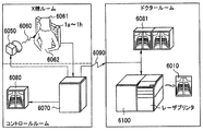
図12は、本発明の実施形態にかかる放射線撮像システムの概略構成を示す模式図である。本実施形態にかかる放射線撮像システムには、前記いずれかの実施形態にかかる放射線検出装置1a~1hが適用される。
図12は、本発明の実施形態にかかる放射線撮像システムの概略構成を示す模式図である。本実施形態にかかる放射線撮像システムには、前記いずれかの実施形態にかかる放射線検出装置1a~1hが適用される。
放射線発生手段の例であるX線チューブ6050は、放射線の例であるX線6060を発生させる。そしてX線6060は、患者または被検者6061の撮影対象部位(ここでは胸部6062示す)を透過し、放射線検出手段の例である放射線検出装置1a~1hに入射する。放射線検出装置1a~1hに入射したX線には、患者または被検者6061の体の内部の情報が含まれている。シンチレータ123は、X線の入射に対応して発光する。放射線検出パネル12の光電変換素子122は、シンチレータ123がX線に応じて発した光を光電変換する。これにより、患者または被検者6061の体の内部の情報を、電気信号として得られる。放射線検出装置1a~1hの電気基板14には信号処理回路が設けられており、この信号処理回路は、この電気信号をデジタル形式に変換し、信号処理手段の例であるイメージプロセッサ6070に送信する。イメージプロセッサ6070は、送信された電気信号に画像処理などの所定の信号処理を施し、制御室に設けられる表示手段の例であるディスプレイ6080に出力して表示させる。このため、検者等は、患者または被検者6061の体の内部の情報を画像として観察できる。
また、イメージプロセッサ6070は、この電気信号を、伝送手段の例である電話、LAN、インターネットなどのネットワーク6090等により遠隔地へ転送できる。たとえば、イメージプロセッサ6070は、この電気信号を、別の場所のドクタールームなど設けられた表示手段の例であるディスプレイ6081に送信して表示させることができる。または光ディスク等の記録手段に保存することができる。このため、遠隔地の医師が診断することも可能である。また記録手段の例であるフィルムプロセッサ6100によりフィルム6010に記録することもできる。さらに、イメージプロセッサ6070は、この電気信号をフィルムプロセッサ6100に送信することもできる。フィルムプロセッサ6100は、受信した電気信号から、レーザープリンタを用いて、患者または被検者6061の体の内部の情報を含むフィルム6010を作成することができる。
以上、本発明を実施形態に基づいて詳述してきたが、本発明はこれら特定の実施形態に限られるものではなく、この発明の要旨を逸脱しない範囲の様々な形態も本発明に含まれる。さらに、上述した各実施形態は本発明の一実施形態を示すものにすぎず、各実施形態を適宜組み合わせることも可能である。
この出願は2013年11月25日に出願された日本国特許出願第2013-243172からの優先権を主張するものであり、その内容を引用してこの出願の一部とするものである。
1a~1h:放射線検出装置、11:筐体、111:上カバー、112:フレーム、113:筺体蓋、12:放射線検出パネル、13:シャシー、16a:緩衝シート、17a,17g:光源部、18a~18c:光源保持機構、19:ストッパー、21:ネジ、22:シャシー保持機構
Claims (13)
- 基板の第1面に配置された複数の光電変換素子と、前記基板の前記第1面の側に配置されたシンチレータと、を有する放射線検出パネルと、
前記基板の前記第1面とは反対側の第2面側に配置され、前記複数の光電変換素子に光を照射する光源部と、
前記光源部と対向する面に前記複数の光電変換素子に対応した開口を有する箱部と、前記開口を覆うように設けられた放射線を前記放射線検出パネルに透過させる蓋部と、を含み、前記放射線検出パネルおよび前記光源部を内包する筺体と、
前記蓋部と前記第2面との間において前記第2面と直交する方向に変位可能に前記光源部を支持する光源支持部と、
を有することを特徴とする放射線検出装置。 - 前記光源部と前記放射線検出パネルとの間には空気層が設けられることを特徴とする請求項1に記載の放射線検出装置。
- 前記光源部は可撓性を有する光学部材を含み、
前記可撓性を有する光学部材が前記光源支持部であることを特徴とする請求項1又は2に記載の放射線検出装置。 - 前記光源支持部は、前記光源部の前記放射線検出パネルの側の少なくとも一部を支持する光源支持機構を含み、
前記光源支持機構は、前記蓋部から前記光源部に対して前記第2面と直交する方向に加わった衝撃を減衰させる減衰機構を含むことを特徴とする請求項1から3のいずれか1項に記載の放射線検出装置。 - 前記光源支持部は、前記光源部と前記蓋部との間に配置された緩衝部材を更に含むことを特徴とする請求項1から4のいずれか1項に記載の放射線検出装置。
- 前記緩衝部材は、前記光源部の前記蓋部の側の表面の全面を覆う緩衝シートであることを特徴とする請求項5に記載の放射線検出装置。
- 前記緩衝部材は、前記光源部の前記蓋部の側の表面のうち前記複数の光電変換素子が配置された前記放射線検出パネルの領域に応じた領域の外側に設けられる緩衝シートであることを特徴とする請求項5に記載の放射線検出装置。
- 前記箱部に接合され前記放射線検出パネルを支持するパネル支持部を更に有し、
前記パネル支持部は、前記放射線検出パネルの側の表面で前記放射線検出パネルを支持するシャシーと、前記シャシーの前記放射線検出パネルの側の表面と反対側の面を前記箱部に接合する複数の脚部と、を含むことを特徴とする請求項1から7のいずれか1項に記載の放射線検出装置。 - 前記光源支持部と前記パネル支持部との間に、前記光源部の変位を規制するストッパーが設けられることを特徴とする請求項8に記載の放射線検出装置。
- 前記箱部は、前記蓋部が接合されたカバー部と、前記カバー部が接合されたフレーム部と、を含むことを特徴とする請求項1から8のいずれか1項に記載の放射線検出装置。
- 前記光源支持部は、前記カバー部に接合されており、
前記カバー部と前記フレーム部とは分離可能に接合されており、
前記光源部は、前記筺体に着脱可能に配置されていることを特徴とする請求項10に記載の放射線検出装置。 - 前記パネル支持部は、前記第2面と直交する方向に変位可能に前記放射線検出パネルを支持し、
前記光源支持部と前記パネル支持部は、互いに協調して変位することを特徴とする請求項8または9に記載の放射線検出装置。 - 放射線を検出する放射線検出手段と、
前記放射線検出手段からの信号を処理する信号処理手段と、
前記信号処理手段からの信号を記録するための記録手段と、
前記信号処理手段からの信号を表示するための表示手段と、
前記信号処理手段からの信号を伝送するための伝送手段と、
を有し、
前記放射線検出手段には、請求項1から12のいずれか1項に記載の放射線検出装置が適用されることを特徴とする放射線撮像システム。
Applications Claiming Priority (2)
| Application Number | Priority Date | Filing Date | Title |
|---|---|---|---|
| JP2013-243172 | 2013-11-25 | ||
| JP2013243172A JP2015102419A (ja) | 2013-11-25 | 2013-11-25 | 放射線検出装置および放射線撮像システム |
Publications (1)
| Publication Number | Publication Date |
|---|---|
| WO2015075877A1 true WO2015075877A1 (ja) | 2015-05-28 |
Family
ID=53179172
Family Applications (1)
| Application Number | Title | Priority Date | Filing Date |
|---|---|---|---|
| PCT/JP2014/005526 Ceased WO2015075877A1 (ja) | 2013-11-25 | 2014-10-31 | 放射線検出装置および放射線撮像システム |
Country Status (2)
| Country | Link |
|---|---|
| JP (1) | JP2015102419A (ja) |
| WO (1) | WO2015075877A1 (ja) |
Families Citing this family (1)
| Publication number | Priority date | Publication date | Assignee | Title |
|---|---|---|---|---|
| JP6931604B2 (ja) * | 2017-12-22 | 2021-09-08 | 富士フイルム株式会社 | 放射線検出装置 |
Citations (9)
| Publication number | Priority date | Publication date | Assignee | Title |
|---|---|---|---|---|
| JPH11513221A (ja) * | 1996-07-08 | 1999-11-09 | フィリップス エレクトロニクス エヌ ベー | 半導体x線検出器を有するx線検査装置 |
| JP2002014168A (ja) * | 2000-06-27 | 2002-01-18 | Canon Inc | X線撮像装置 |
| JP2004033659A (ja) * | 2002-07-08 | 2004-02-05 | Shimadzu Corp | 放射線撮像装置 |
| WO2006046384A1 (ja) * | 2004-10-29 | 2006-05-04 | Shimadzu Corporation | 放射線検出器 |
| JP2007199079A (ja) * | 2000-11-30 | 2007-08-09 | Canon Inc | X線撮像装置 |
| JP2008134237A (ja) * | 2006-11-01 | 2008-06-12 | Canon Inc | 放射線撮像装置 |
| JP2008304460A (ja) * | 2007-06-07 | 2008-12-18 | General Electric Co <Ge> | 非金属閉鎖容器を持つディジタルx線検出器のemi遮蔽 |
| JP2010078385A (ja) * | 2008-09-25 | 2010-04-08 | Fujifilm Corp | 放射線画像検出装置 |
| JP2010523997A (ja) * | 2007-04-12 | 2010-07-15 | コーニンクレッカ フィリップス エレクトロニクス エヌ ヴィ | シンチレータの空間利得分布の決定 |
-
2013
- 2013-11-25 JP JP2013243172A patent/JP2015102419A/ja active Pending
-
2014
- 2014-10-31 WO PCT/JP2014/005526 patent/WO2015075877A1/ja not_active Ceased
Patent Citations (9)
| Publication number | Priority date | Publication date | Assignee | Title |
|---|---|---|---|---|
| JPH11513221A (ja) * | 1996-07-08 | 1999-11-09 | フィリップス エレクトロニクス エヌ ベー | 半導体x線検出器を有するx線検査装置 |
| JP2002014168A (ja) * | 2000-06-27 | 2002-01-18 | Canon Inc | X線撮像装置 |
| JP2007199079A (ja) * | 2000-11-30 | 2007-08-09 | Canon Inc | X線撮像装置 |
| JP2004033659A (ja) * | 2002-07-08 | 2004-02-05 | Shimadzu Corp | 放射線撮像装置 |
| WO2006046384A1 (ja) * | 2004-10-29 | 2006-05-04 | Shimadzu Corporation | 放射線検出器 |
| JP2008134237A (ja) * | 2006-11-01 | 2008-06-12 | Canon Inc | 放射線撮像装置 |
| JP2010523997A (ja) * | 2007-04-12 | 2010-07-15 | コーニンクレッカ フィリップス エレクトロニクス エヌ ヴィ | シンチレータの空間利得分布の決定 |
| JP2008304460A (ja) * | 2007-06-07 | 2008-12-18 | General Electric Co <Ge> | 非金属閉鎖容器を持つディジタルx線検出器のemi遮蔽 |
| JP2010078385A (ja) * | 2008-09-25 | 2010-04-08 | Fujifilm Corp | 放射線画像検出装置 |
Also Published As
| Publication number | Publication date |
|---|---|
| JP2015102419A (ja) | 2015-06-04 |
Similar Documents
| Publication | Publication Date | Title |
|---|---|---|
| JP5675062B2 (ja) | X線画像撮影装置 | |
| JP5827856B2 (ja) | カセッテ | |
| JP6609105B2 (ja) | 放射線撮像装置および放射線撮像システム | |
| US7723693B2 (en) | Radiation detecting apparatus and radiation imaging system using the same | |
| JP5881550B2 (ja) | 電子カセッテ | |
| JP2012073186A (ja) | 放射線撮影用電子カセッテ | |
| US20130083900A1 (en) | Cassette for radiographic imaging | |
| US8415649B2 (en) | Radiation imaging apparatus | |
| KR101927690B1 (ko) | 방사선 촬상 시스템 | |
| CN115721326A (zh) | 放射线摄像装置和放射线摄像系统 | |
| JP6116641B2 (ja) | カセッテ | |
| WO2015075877A1 (ja) | 放射線検出装置および放射線撮像システム | |
| JP2015138008A (ja) | 放射線撮影装置、放射線撮影システム | |
| JP2019152483A (ja) | 放射線撮像装置及び放射線撮像システム | |
| JP2011194212A (ja) | 放射線検出装置 | |
| JP2010164881A (ja) | 放射線画像撮影用のカセッテ | |
| JP2007163216A (ja) | 放射線検出装置および放射線撮像システム | |
| JP6472432B2 (ja) | 放射線撮像システム | |
| JP2016151446A (ja) | 放射線撮像装置及び放射線撮像システム | |
| JP2000352587A (ja) | X線平面検出装置 | |
| WO2015049832A1 (ja) | 放射線画像検出器及び放射線画像検出システム | |
| WO2018159112A1 (ja) | 放射線撮像装置および放射線撮像システム | |
| JP2011117760A (ja) | 平面型x線検出装置 | |
| JP2009063475A (ja) | シンチレータプレート及び放射線画像撮影装置 | |
| JP2023000693A (ja) | 放射線検出器 |
Legal Events
| Date | Code | Title | Description |
|---|---|---|---|
| 121 | Ep: the epo has been informed by wipo that ep was designated in this application |
Ref document number: 14864776 Country of ref document: EP Kind code of ref document: A1 |
|
| NENP | Non-entry into the national phase |
Ref country code: DE |
|
| 122 | Ep: pct application non-entry in european phase |
Ref document number: 14864776 Country of ref document: EP Kind code of ref document: A1 |